physical models of the toroidal dipole - digital commons
TRANSCRIPT
Exigence
Volume 2 | Issue 1 Article 7
2018
Physical Models of the Toroidal DipoleArmian HanelliCalifornia Institute of Technology, [email protected]
Amanuel [email protected]
Walerian MajewskiNorthern Virginia Community College, [email protected]
Follow this and additional works at: https://commons.vccs.edu/exigence
Part of the Other Physics Commons
This Article is brought to you for free and open access by Digital Commons @ VCCS. It has been accepted for inclusion in Exigence by an authorizededitor of Digital Commons @ VCCS. For more information, please contact [email protected].
Recommended CitationHanelli, A., Eshete, A., & Majewski, W. (2018). Physical Models of the Toroidal Dipole. Exigence, 2 (1). Retrieved fromhttps://commons.vccs.edu/exigence/vol2/iss1/7

Motivation
Figure 1. James Clerk Maxwell
We took our research topic directly from the Father of Electrodynamics
(Maxwell, 1861): “Let there be a circular ring of uniform section, lapped uniformly
with covered wire. It may be shown that if an electric current is passed through this
wire, a magnet placed within the coil of wire will be strongly affected, but no
magnetic effect will be produced on any external point. “The effect will be that of
a magnet bent round till its two poles are in contact”.
Introduction
The toroidal solenoid is a unique object exhibiting many interesting
properties and very rich physics, generally not very well known, besides what we
read in the college physics textbooks. The current flowing in its winding is
characterized by a new electromagnetic property called toroidal dipole, or anapole
(pole-less) moment (Dubovik et al, 1989). These dipoles recently became a subject
of an extensive theoretical and experimental study. But the standard textbook
presentations of the multipole expansions of electromagnetic fields are usually
incomplete, since they are valid only in the regions outside of localized currents.
As a result, they miss the existence of, and do not even mention the toroidal
moments.
Everybody knows the properties of a bar magnet. Its strength, called the
magnetic dipole moment μ, is characterized by its response to an external magnetic
1
Hanelli et al.: Physical Models of the Toroidal Dipole
Published by Digital Commons @ VCCS, 2018
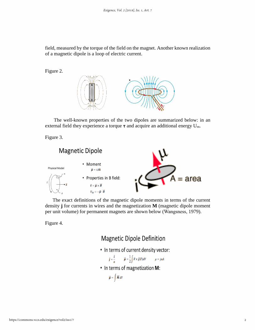
field, measured by the torque of the field on the magnet. Another known realization
of a magnetic dipole is a loop of electric current.
Figure 2.
The well-known properties of the two dipoles are summarized below: in an
external field they experience a torque τ and acquire an additional energy Um.
Figure 3.
The exact definitions of the magnetic dipole moments in terms of the current
density j for currents in wires and the magnetization M (magnetic dipole moment
per unit volume) for permanent magnets are shown below (Wangsness, 1979).
Figure 4.
2
Exigence, Vol. 2 [2018], Iss. 1, Art. 7
https://commons.vccs.edu/exigence/vol2/iss1/7

i is the current in the loop, a is the cross-sectional area of the wire, and A
is the area surrounded by the loop, dV is the volume element, and r is a position
vector of a point inside the wiring for the electric case or inside a magnet for the
magnetized material.
Toroidal systems
There is one more elementary magnetic system, frequently overlooked – the
toroidal dipole. If we follow the suggestion of the Father of Electrodynamics and
bend a bar magnet into shape of a donut, thus joining its ends, with a north pole
coming in contact with the south pole – then its entire magnetic field, represented
by the field lines on Figure 2 above will be concentrated inside, and no field will
be left even in the hole of the torus. Such a magnet has no magnetic poles. Red
magnetic lines below are totally confined within the torus, with the blue “bound”
or “magnetization” currents of the atomic electrons flowing “poloidally” (along the
polar lines) on the surface of the magnet.
Figure 5.
The question to ask is: would this toroid experience any force, if placed in the
external magnetic or electric field, even if it does not produce any external field
itself? This paper is devoted to answering this question.
3
Hanelli et al.: Physical Models of the Toroidal Dipole
Published by Digital Commons @ VCCS, 2018

A similar electric system is formed by bending a straight solenoid connected to
a DC power supply into a torus, and observing the same effect that this electric
toroid also confines its magnetic field to its interior.
Figure 6.
It was shown (Dubovik, 1989), that both toroids will interact with an
external (coming from sources outside of them) magnetic field B through their
toroidal magnetic dipole moments with following formulas for the electric or
magnetic toroids :
Figure 7.
Magnetic dipole moment μ of a small thin current loop can be calculated from a
textbook formula μ = iA = jaA, where j is the current density, i is the current, a is
the cross-sectional area of the wire (and so i = ja) and A is the area surrounded by
the loop.
4
Exigence, Vol. 2 [2018], Iss. 1, Art. 7
https://commons.vccs.edu/exigence/vol2/iss1/7

Figure 8. Red arrows are magnetization vectors M, j is the surface current density,
and the green vector tm is the toroidal dipole moment directed along the torus’
symmetry axis.
By using an exact mathematical analogy between a current loop and the
magnetization loop of the toroid, with j replaced by M, the toroidal dipole moment
tm for a thin small toroid should be equal approximately tm = MaA, where a is the
cross-sectional area of the torus (inside a blue loop), and A is the area surrounded
by the toroid, if we count its radius to the central line of the torus (where the red
arrows are). In our toroid the conditions of a small thin toroid (a<< A) are not
satisfied, so that we do not have a reliable theoretical formula for tm.
Figure 9. Comparison of two toroids
Current-generated, small (point) toroid with the current density j has a toroidal
dipole moment tm and interacts with the external field B via the following torque τ
and potential energy Um (Dubovik, 1989):
5
Hanelli et al.: Physical Models of the Toroidal Dipole
Published by Digital Commons @ VCCS, 2018
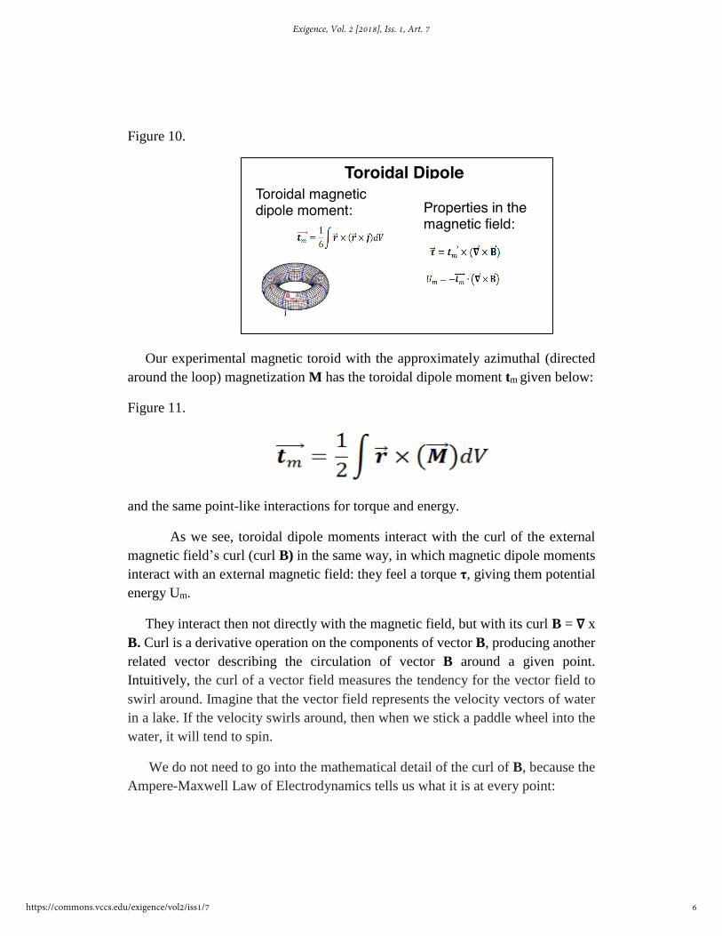
Figure 10.
Our experimental magnetic toroid with the approximately azimuthal (directed
around the loop) magnetization M has the toroidal dipole moment tm given below:
Figure 11.
and the same point-like interactions for torque and energy.
As we see, toroidal dipole moments interact with the curl of the external
magnetic field’s curl (curl B) in the same way, in which magnetic dipole moments
interact with an external magnetic field: they feel a torque τ, giving them potential
energy Um.
They interact then not directly with the magnetic field, but with its curl B = ∇ x
B. Curl is a derivative operation on the components of vector B, producing another
related vector describing the circulation of vector B around a given point.
Intuitively, the curl of a vector field measures the tendency for the vector field to
swirl around. Imagine that the vector field represents the velocity vectors of water
in a lake. If the velocity swirls around, then when we stick a paddle wheel into the
water, it will tend to spin.
We do not need to go into the mathematical detail of the curl of B, because the
Ampere-Maxwell Law of Electrodynamics tells us what it is at every point:
Toroidal Dipole
Properties in the magnetic field:
Toroidal magnetic dipole moment:
6
Exigence, Vol. 2 [2018], Iss. 1, Art. 7
https://commons.vccs.edu/exigence/vol2/iss1/7
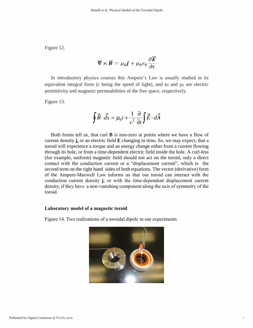
Figure 12.
In introductory physics courses this Ampere’s Law is usually studied in its
equivalent integral form (c being the speed of light), and ε0 and µ0 are electric
permittivity and magnetic permeabilities of the free space, respectively.
Figure 13.
Both forms tell us, that curl B is non-zero at points where we have a flow of
current density j, or an electric field E changing in time. So, we may expect, that a
toroid will experience a torque and an energy change either from a current flowing
through its hole, or from a time-dependent electric field inside the hole. A curl-less
(for example, uniform) magnetic field should not act on the toroid, only a direct
contact with the conduction current or a “displacement current”, which is the
second term on the right hand sides of both equations. The vector (derivative) form
of the Ampere-Maxwell Law informs us that our toroid can interact with the
conduction current density j, or with the time-dependent displacement current
density, if they have a non-vanishing component along the axis of symmetry of the
toroid.
Laboratory model of a magnetic toroid
Figure 14. Two realizations of a toroidal dipole in our experiments
7
Hanelli et al.: Physical Models of the Toroidal Dipole
Published by Digital Commons @ VCCS, 2018

Our toroidal magnet has a small deviation from the strict ideal toroid - for
practical reasons (it is not easy to magnetize a neodymium ring strictly
circumferentially), it was constructed from 12 magnetic dipole arc, or ‘pie’,
segments. When put in a ring a chain of magnetic dipoles back to back, with N-pole
of one touching the S-pole of the next one, the magnets stick to each other with a
force of about 70 lb. Each segment is magnetized perpendicularly to its middle
radial line. Because of this, its magnetization is not strictly azimuthal, thus the torus
has a net dodecapole magnetic moment with a very small and very short-ranged
external magnetic field of the 12-pole polarity. The magnetic dipole moments of all
segments add to a net vector of zero, of course. We made our magnetic toroid from
magnetized neodymium NdFeB grade 52 segments with inner radius 1”, outer
radius 2”, vertex angle 300, and square cross section with an area 1”x1”.
Figure 15. Red arrows show directions of magnetic dipole moments creating the
toroidal moment
8
Exigence, Vol. 2 [2018], Iss. 1, Art. 7
https://commons.vccs.edu/exigence/vol2/iss1/7

Magnets have 1.48 Tesla residual internal flux density (magnetic field) B, as
measured in the gap (black insert on the toroid’s picture) left in the toroid. Its
uniform magnetization is M=B/μ0 = 1.18x10⁶
A/m, close to circumferential.
Surface bound current density is K = M = 1.18x10⁶ A/m, total equivalent
magnetization current going through the hole of the torus is 2.82x10⁵ A. Mass of
the toroid is 1.184 kg, moment of inertia calculated about its big diameter: I =
1.01x10⁻³
kg·m2
Figure 16.
Arrows show ideal (on left) vs actual (on right) magnetization directions:
Figure 17. Shown below is measured radial field leaking on the ring’s outside rim
because of the sudden changes of the magnetization direction: up to 50-80 mT on
the magnet’s surface, which is 5% of the internal B-field, together with a weak
magnetic field leakage from the side of the toroid as visualized with iron filings:
Discontinuous magnetization directions introduce dodecapole (12-pole)
moment to our torus in addition to toroidal dipole moment. We checked that its
escaping magnetic field range is up to 2 cm on both rims of the torus, and so it will
not practically interact with a current passing through its center.
-200
-100
0
100
1 2 3 4 5 6 7 8 9 10 11 12
Mag
ne
tic
Fie
ld S
ten
gth
(m
T)
Position
Magnetic Field Strength vs. Position around Torus
9
Hanelli et al.: Physical Models of the Toroidal Dipole
Published by Digital Commons @ VCCS, 2018

Figure 18. Radial component of magnetic field escaping from the outside rim of the ring
Figure 19.
Our toroid is not expected to react to a uniform, curl-less magnetic field; and
yet, it actually feels a strong torque, when placed in a uniform field inside Helmholtz
coils (below). This is a demonstration of the dodecapole component of our toroid.
Figure 20.
10
Exigence, Vol. 2 [2018], Iss. 1, Art. 7
https://commons.vccs.edu/exigence/vol2/iss1/7
Experiments with magnetic toroid
The formula for torque τ and energy Um and the Ampere-Maxwell Law
suggest two experiments:
Experiment 1: immersing the toroid in an electrolyte with a volume DC
current density j to measure its torque on the toroid and so find the toroid moment.
Experiment 2: immersing the toroid in time-dependent electric field E, and
finding the torque of the displacement current on the toroid.
Experimenting within an electrolyte is not practical. We cannot create a
uniform current density everywhere inside the toroid. Instead we did a variation of
Experiment 1: placing the toroid near linear currents and seeing what happens.
Currents are carrying inside them the curl B represented by the current density. This
density must overlap with the toroid, if there is to be an interaction. We assume that
the toroid’s magnetization is not changed by the external magnetic fields we apply,
which are by a factor of 105 smaller than the inner field in the toroid. We checked
the torque for two situations – when the current is passing inside the toroid’s hole
or outside of it.
Effective interaction between toroid and an electric current
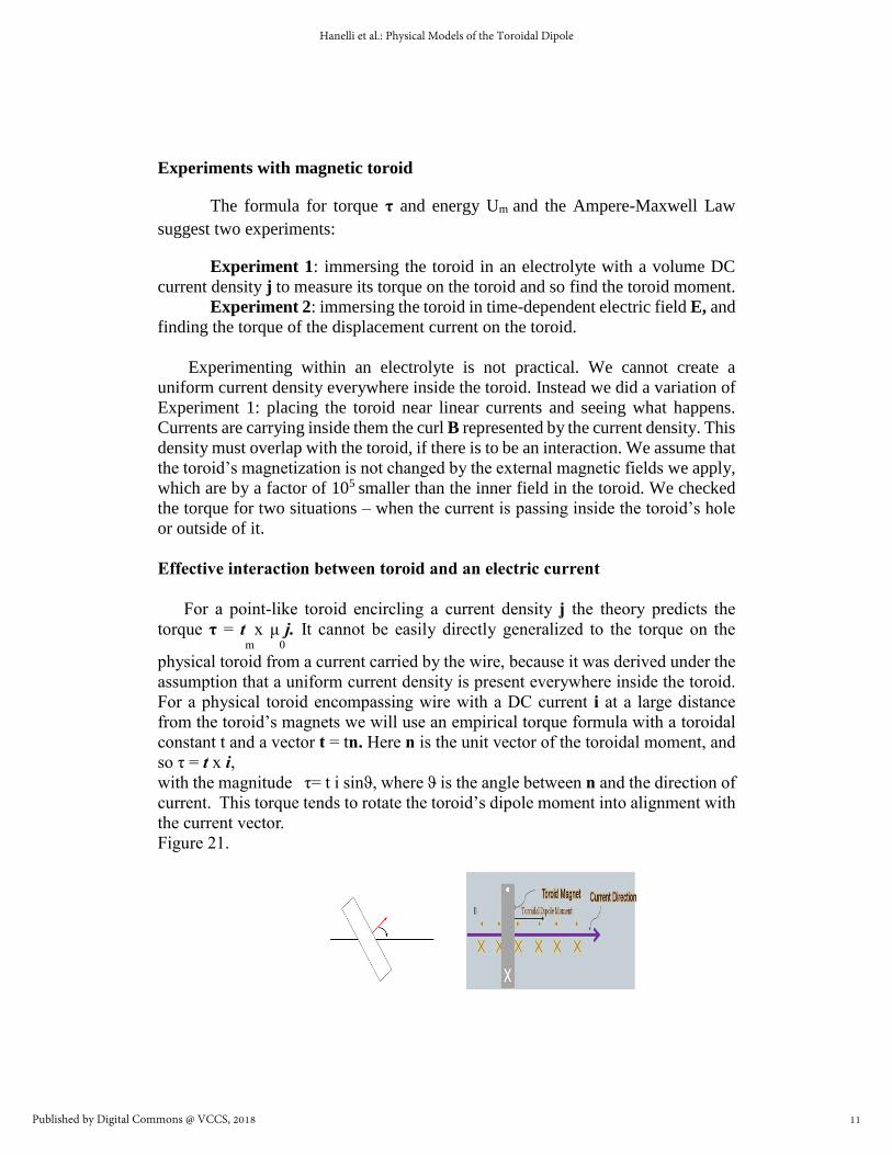
For a point-like toroid encircling a current density j the theory predicts the
torque τ = tm
x μ0
j. It cannot be easily directly generalized to the torque on the
physical toroid from a current carried by the wire, because it was derived under the
assumption that a uniform current density is present everywhere inside the toroid.
For a physical toroid encompassing wire with a DC current i at a large distance
from the toroid’s magnets we will use an empirical torque formula with a toroidal
constant t and a vector t = tn. Here n is the unit vector of the toroidal moment, and
so τ = t x i, with the magnitude τ= t i sinϑ, where ϑ is the angle between n and the direction of
current. This torque tends to rotate the toroid’s dipole moment into alignment with
the current vector.
Figure 21.
11
Hanelli et al.: Physical Models of the Toroidal Dipole
Published by Digital Commons @ VCCS, 2018

The actual torque on toroid’s dipoles is created by the wire’s magnetic field. This is intuitively to be expected:
individual circumferential magnetic dipoles try to align with the wire’s circular
magnetic lines. It is easy to notice that in a toroid’s equilibrium position the
magnetization loops will be overlapping with the circular magnetic lines of the
current, minimizing the toroid’s magnetic energy.
It may be also said that the toroidal dipole moment interacts in effect with the
curl B, which is produced inside the wire – and so inside the hole of the toroid – by
the current density, if the wire passes inside the toroid.
Instead of trying to measure directly a very small torque, we use an old
torsional pendulum method first exploited in 1883 by Carl Friedrich Gauss (of the
gauss unit fame) to measure the Earth’s magnetic field. Interaction of the toroid
with an electric current can be measured from the torsional oscillations of torus
suspended near the current-carrying wire on a monofilament fishing line, with
torsional constant k.
We confirmed a contrasting behavior of a toroidal dipole and of a magnetic
dipole. The ring on the right, below, is magnetized perpendicular to its plane and is
then a magnetic dipole oriented along ring’s axis. It aligns itself with the magnetic
field perpendicular to the wire, while toroid’s axis aligns with the current direction
Figure 22.
Theory
Passing a wire (with DC current) inside and outside of the magnetic toroid, we
recorded frequency of toroid’s oscillations as a function of the current.
12
Exigence, Vol. 2 [2018], Iss. 1, Art. 7
https://commons.vccs.edu/exigence/vol2/iss1/7
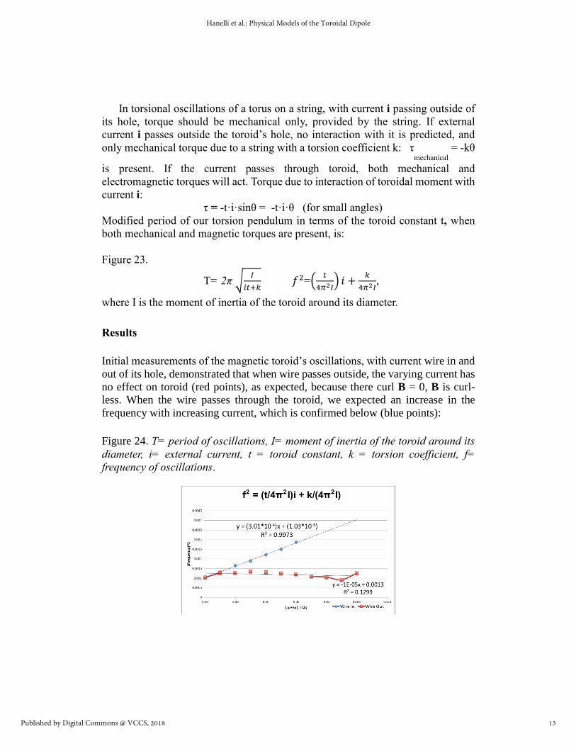
In torsional oscillations of a torus on a string, with current i passing outside of
its hole, torque should be mechanical only, provided by the string. If external
current i passes outside the toroid’s hole, no interaction with it is predicted, and
only mechanical torque due to a string with a torsion coefficient k: τmechanical
= -kθ
is present. If the current passes through toroid, both mechanical and
electromagnetic torques will act. Torque due to interaction of toroidal moment with
current i:
τ = -t·i·sinθ = -t·i·θ (for small angles)
Modified period of our torsion pendulum in terms of the toroid constant t, when
both mechanical and magnetic torques are present, is:
Figure 23.
T= 2π √𝐼
𝑖𝑡+𝑘 𝑓2=(
𝑡
4𝜋2𝐼) 𝑖 +
𝑘
4𝜋2𝐼,
where I is the moment of inertia of the toroid around its diameter.
Results
Initial measurements of the magnetic toroid’s oscillations, with current wire in and
out of its hole, demonstrated that when wire passes outside, the varying current has
no effect on toroid (red points), as expected, because there curl B = 0, B is curl-
less. When the wire passes through the toroid, we expected an increase in the
frequency with increasing current, which is confirmed below (blue points):
Figure 24. T= period of oscillations, I= moment of inertia of the toroid around its
diameter, i= external current, t = toroid constant, k = torsion coefficient, f=
frequency of oscillations.
13
Hanelli et al.: Physical Models of the Toroidal Dipole
Published by Digital Commons @ VCCS, 2018

To find the toroidal constant t, which can be thought of as “an effective toroidal
moment” for our experiment, equal to the amount of torque per one ampere of
current, we did several series of measurements of the frequency of oscillations of
our freely suspended toroid as a function of the current i in a wire passing through
the opening of the torus.
Figure 25.
From a typical graph of f2 = T-2 vs i we can extract toroidal and torsion constants:
from the slope = 2.97x10
-4
1/As
2
we get t=(4π
2
I) (slope) = 1.18x10
-5
Nm/A, and
from the intercept k = 4.66x10
-5
Nm.
The important numerical result of this experiment: the torque on toroid from 1 A
current passing through its hole equals t = 1.18x10
-5
Nm/A.
The torque amplitude at 7 A in our experiments was only 0.0826 milli-Nm.
Our calculated from this experiment toroidal dipole moment, when using the
current density averaged over area A of the torus, jav = i/A, turns out to be:
τ= tm µ0 (i/A) leads to tm = tA/µ0 = 4.28x10⁻² Am3.
Experiment 2
Figure 26.
We unsuccessfully tried to observe a torque on the toroid placed inside a
capacitor with a sudden drop of the electric field in it, which was supposed to result
14
Exigence, Vol. 2 [2018], Iss. 1, Art. 7
https://commons.vccs.edu/exigence/vol2/iss1/7

in a short impulse of torque of the collapsing displacement current acting on the
toroid.
Interaction with displacement current had no measurable or even observable effect.
We estimated that the rate of change of the electric field collapsing by ΔE in time
tc was
ΔE/tc = 4.44x10¹⁴ V/s and so the displacement current density was
ε0 ΔE/tc = 3.93x10³ A/m2 to be compared with the current density in the wire
j = i/a = 6.32x10⁶ A/m2. The average torque on toroid (using the theoretical tm) was
expected to be
τ= tm μ0 ε0 ΔE/tc = μ0 (MaA) (ε0 ΔE/tc) = 4π10-7 (Tm/A) (2.41 Am3) (3.93x10³
A/m2) = 1.19x10⁻² Nm, very small.
Electric toroid
We tried to measure the toroidal moment of the DC toroidal coil. We do not have
any results here, because of several experimental difficulties.
15
Hanelli et al.: Physical Models of the Toroidal Dipole
Published by Digital Commons @ VCCS, 2018

Figure 27.
Experimental difficulties with the electric toroid:
Toroid’s powering and winding wires would overheat
Extra torque applied by powering wires
Iron core was magnetized
Its winding has a pitch angle, giving the coil a net magnetic dipole
moment from its net circumferential current. This magnetic dipole
presence obscured toroidal interactions.
Powering toroidal coil from attached to it batteries has increased its
inertia, making it less responsive to the torque
Possible future experiments
Toroids have many other peculiar properties. In vacuum, the magnetic field
outside the toroidal dipole is zero. But fields do appear outside the dipole in an
electrodynamic medium with permittivity ε0 and permeability μ0; they are
16
Exigence, Vol. 2 [2018], Iss. 1, Art. 7
https://commons.vccs.edu/exigence/vol2/iss1/7

proportional to ε0μ0 -1, and arise because of the fact that, according to the
macroscopic electrodynamics of a homogeneous medium, the medium should be
considered as permeating the dipole itself (Ginsburg, 1989). We plan to imbed the
magnetic toroid in a medium of known ε0 and μ0 and try to detect this outside field.
Toroidal magnet as an electric-dipole antenna: if we rotate our magnetic toroid
around its diameter, we could observe the theoretically predicted effect of the
magnetic field (which is normally locked inside a toroid at rest) escaping outside
of the rotating toroid, as a part of the quasi-static, or radiation, field of the electric-
dipole type. An oscillating electric and magnetic field will be generated around a
fixed conducting loop placed near the rotating magnetic toroid (Fernandez-
Corbaton, 2017). Rotating toroid should display the same radiated fields as an
electric toroid with AC current.
Figure 28. Toroid on a rotator
Toroids in fundamental physics
Figure 29.
17
Hanelli et al.: Physical Models of the Toroidal Dipole
Published by Digital Commons @ VCCS, 2018

Atoms and nuclei were found to have toroidal dipole moments because of
presence of a parity-nonconserving (non-mirror symmetric) weak nuclear force
(Wood et al, 1997) . For example, while the normal spherically symmetric
hydrogen atom has its electron moving along a classical circular orbit under the
attraction of the central electric force mediated by virtual photons, in the presence
of the weak nuclear force mediated by the Z0 bosons its path becomes slightly
helical, spiraling around the circular coulombic orbit. Such an atom is then a
miniature toroid and has corresponding toroidal, or anapole, moment.
Anapole dark matter theory: physicists propose (Ho C. et al, 2013) that dark
matter, an invisible form of matter that makes up 26 percent of the all the matter
in the universe, may be made out of a type of basic particle possessing a rare,
donut-shaped magnetic field, called an anapole.
Applications of toroidal magnets in technology
Research in the last few years has demonstrated, that static toroidal moments exists
in various materials both microscopically and macroscopically, covering transition
metal ions, biological and chemical macromolecules, bulk crystals and glasses (Talebi et al, 2017).
Figure 30. Miniature toroids are used in artificially engineered electromagnetic
media - toroidal metamaterials. Examples:
Ring-shaped molecular toroidal magnets on the left and a toroidal metamaterial
with a unit cell consisting of four connected square copper wire loops, imbedded
in a dielectric, in the middle. Their toroidal grainy inside magnetization is called
macroscopic toroidization (density of toroidal dipoles), on the right. Unusual
properties of toroidal matter opened a horizon of potential applications in data
18
Exigence, Vol. 2 [2018], Iss. 1, Art. 7
https://commons.vccs.edu/exigence/vol2/iss1/7
storage disks and in designing of low loss metamaterials or metadevices, such as
ultrasensitive sensors and diagnostic tools. (Ye et al, 2013), (Zhao et al, 2016).
Conclusions:
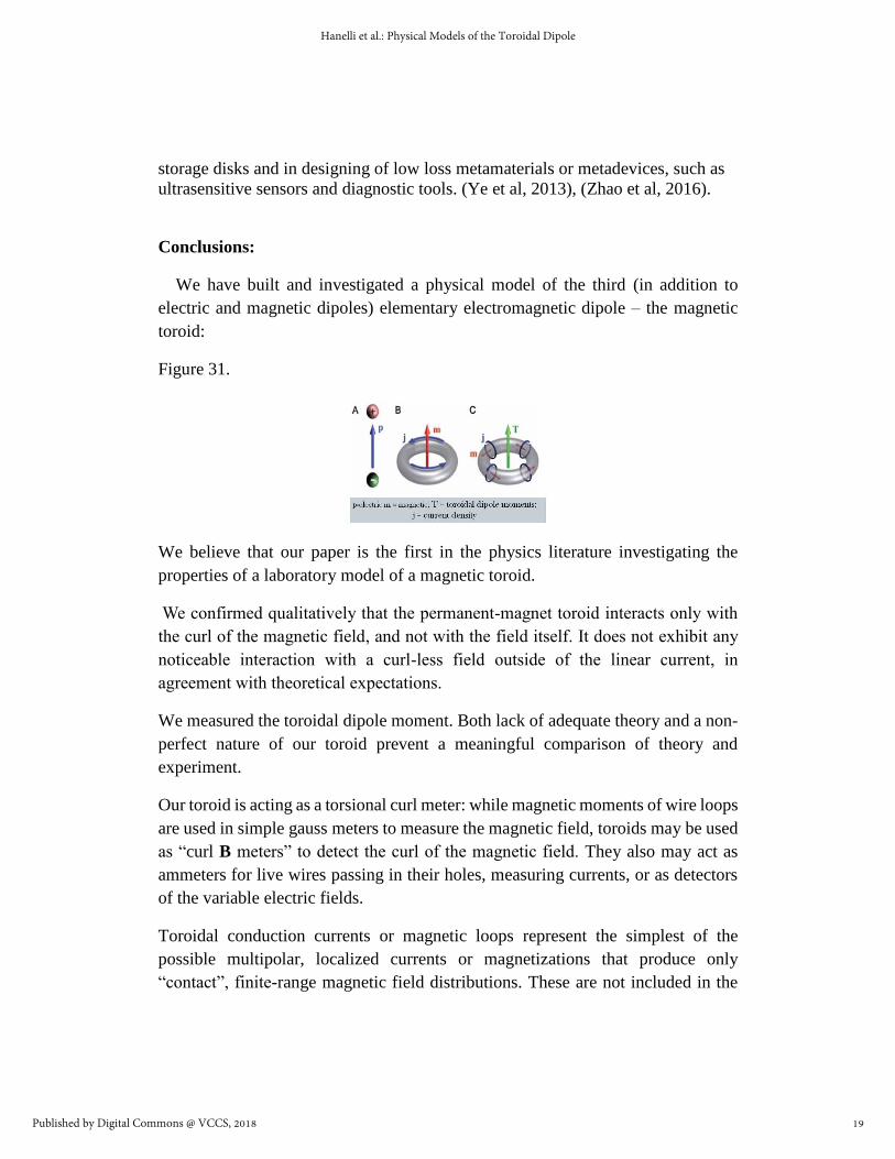
We have built and investigated a physical model of the third (in addition to
electric and magnetic dipoles) elementary electromagnetic dipole – the magnetic
toroid:
Figure 31.
We believe that our paper is the first in the physics literature investigating the
properties of a laboratory model of a magnetic toroid.
We confirmed qualitatively that the permanent-magnet toroid interacts only with
the curl of the magnetic field, and not with the field itself. It does not exhibit any
noticeable interaction with a curl-less field outside of the linear current, in
agreement with theoretical expectations.
We measured the toroidal dipole moment. Both lack of adequate theory and a non-
perfect nature of our toroid prevent a meaningful comparison of theory and
experiment.
Our toroid is acting as a torsional curl meter: while magnetic moments of wire loops
are used in simple gauss meters to measure the magnetic field, toroids may be used
as “curl B meters” to detect the curl of the magnetic field. They also may act as
ammeters for live wires passing in their holes, measuring currents, or as detectors
of the variable electric fields.
Toroidal conduction currents or magnetic loops represent the simplest of the
possible multipolar, localized currents or magnetizations that produce only
“contact”, finite-range magnetic field distributions. These are not included in the
19
Hanelli et al.: Physical Models of the Toroidal Dipole
Published by Digital Commons @ VCCS, 2018

usual multipole expansions describing the field outside of the sources. The simplest
toroidal multipole is a dipole.
Figure 32. What if the Earth was toroidal? (-:
References
1. James Clerk Maxwell (1861), On physical lines of force.
2 . Dubovik, V.M. and Tugushev, V.V. (1989) Toroid Moments in Electrodynamics
and Solid-State Physics, Physics Reports, 4, 145-202.
http://citeseerx.ist.psu.edu/viewdoc/download?doi=10.1.1.205.6316&rep=rep1&t
ype=pdf
3. Wangsness, Roald K. (1979), Electromagnetic Fields, Wiley.
4. Ginsburg, David (1989), Applications of Electrodynamics in Theoretical Physics
and Astrophysics, CRC Press.
5. Fernandez-Corbaton, Ivan, Nanz, Stefan & Rockstuhl, Carsten. (2017) On the
dynamic toroidal multipoles from localized electric current distributions. Nature,
Scientific Reports 7, Article number: 7527.
http://www.nature.com/articles/s41598-017-07474-4
20
Exigence, Vol. 2 [2018], Iss. 1, Art. 7
https://commons.vccs.edu/exigence/vol2/iss1/7

6. Wood, C. S. , Bennett, S. C. , Cho, D., Masterson, B. P. , Roberts, J. L. , Tanner,
C. E. Wieman, (1997) Measurement of Parity Nonconservation and an Anapole
Moment in Cesium. Science, Vol. 275 no. 5307 pp. 1759-1763.
7. Ho, Chiu Man , Scherrer, Robert J., 2013, Anapole Dark Matter, Phys. Lett.
B722, 341 (2013);
https://arxiv.org/abs/1211.0503
https://news.vanderbilt.edu/2013/06/10/dark-matter/
8. Talebi, Nahid, Guo, Surong, van Aken, Peter A., 2017, Theory and
applications of toroidal moments in electrodynamics: their emergence,
characteristics, and technological relevance, Publ. by De Gruyter, Berlin/Boston.
Published Online: 2017-10-07 | DOI: https://doi.org/10.1515/nanoph-2017-0017
https://www.degruyter.com/downloadpdf/j/nanoph.ahead-of-print/nanoph-2017-
0017/nanoph-2017-0017.pdf
9. Ye, Q. W., L Y Guo, M H Li, Y Liu, B X Xiao and H L Yang, 2013, The
magnetic toroidal dipole in steric metamaterial for permittivity sensor
application, The Royal Swedish Academy of Sciences, Physica Scripta, Volume
88, Number 5.
10. Zhao J-F, Zhang Y-W, Li Y-H, Chen Y-Q, Fang K, He L. , 2016, Wireless
power transfer system based on toroidal metamaterials. Acta Phys Sin, 65:168801.
http://wulixb.iphy.ac.cn/EN/abstract/abstract68195.shtml .
Image credits
Figure 1:
Maxwell, J.C. (1890). The Scientific Papers of James Clerk Maxwell. Ed: W. D.
Niven. New York, Dover. Retrieved from
https://commons.wikimedia.org/w/index.php?curid=2311942
Figure 2:
21
Hanelli et al.: Physical Models of the Toroidal Dipole
Published by Digital Commons @ VCCS, 2018

Georgia State University, Department of Physics and Astronomy. Hyperphysics.
Retrieved from http://hyperphysics.phy-
astr.gsu.edu/hbase/magnetic/elemag.html#c1
Figure 5:
Revolvy. Multipole expansion. Retrieved from
https://www.revolvy.com/main/index.php?s=Multipole%20expansion&item_type
=topic.
Figure 30:
National Applied Research Laboratories (2012, December 24). ITRC’s
metamaterial research appeared on Science. Retrieved from
http://www.narlabs.org.tw/en/news/news.php?news_id=472.
Figure 31:
Laboratory for Electro-Optical Simulation (2011, May 3). Toroidal Dipolar
Response in a Metamaterial. Retrieved from
http://science.sciencemag.org/content/330/6010/1510/F1.
Figure 32:
Irigi bloguje (2010, November 28). Toroidal World. Retrieved from
http://irigi.blogspot.com/2010/11/toroidal-world.html
22
Exigence, Vol. 2 [2018], Iss. 1, Art. 7
https://commons.vccs.edu/exigence/vol2/iss1/7