physical metallurgy 8th lecture ms&e 410 d.ast [email protected] 255 4140
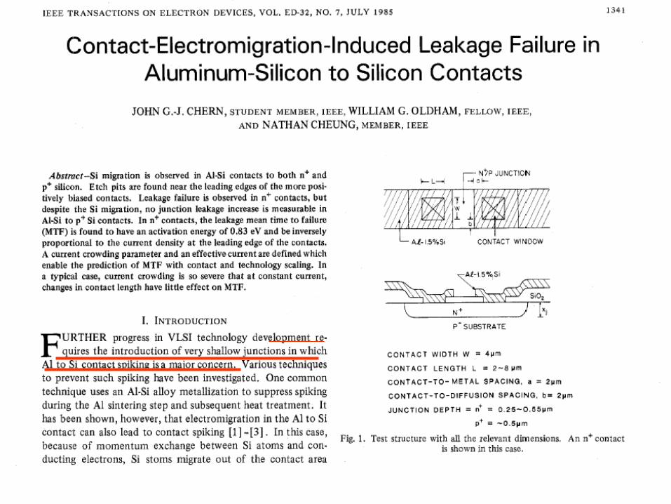
TRANSCRIPT
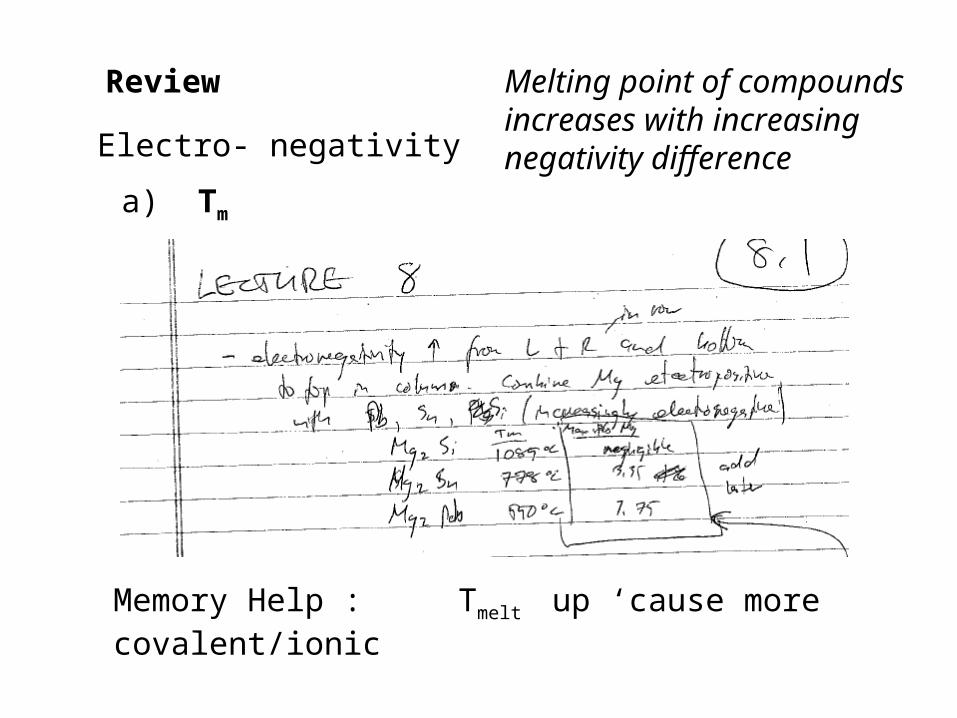
Review
Electro- negativity
Memory Help : Tmelt up ‘cause more covalent/ionic
a) Tm
Melting point of compounds increases with increasing negativity difference
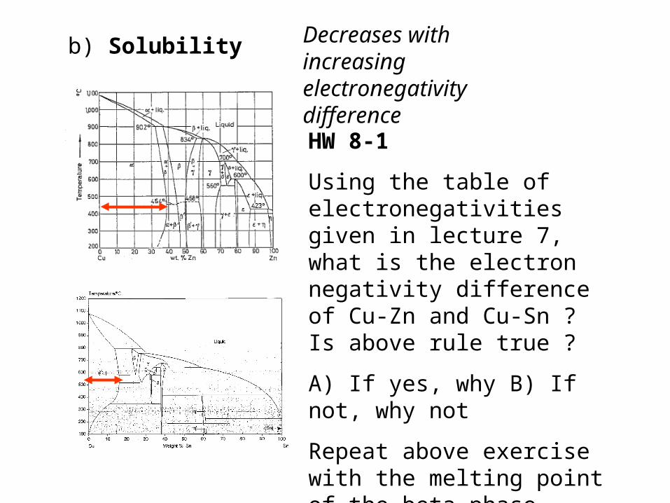
b) Solubility
HW 8-1
Using the table of electronegativities given in lecture 7, what is the electron negativity difference of Cu-Zn and Cu-Sn ? Is above rule true ?
A) If yes, why B) If not, why not
Repeat above exercise with the melting point of the beta phase
Decreases with increasing electronegativity difference
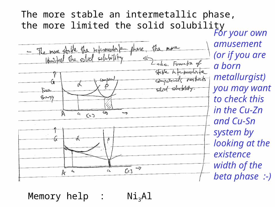
The more stable an intermetallic phase, the more limited the solid solubility
Memory help : Ni3Al
For your own amusement (or if you are a born metallurgist) you may want to check this in the Cu-Zn and Cu-Sn system by looking at the existence width of the beta phase :-)
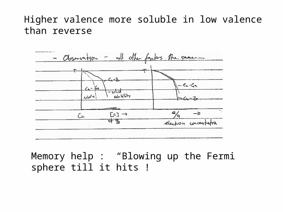
Higher valence more soluble in low valence than reverse
Memory help : “Blowing up the Fermi sphere till it hits !
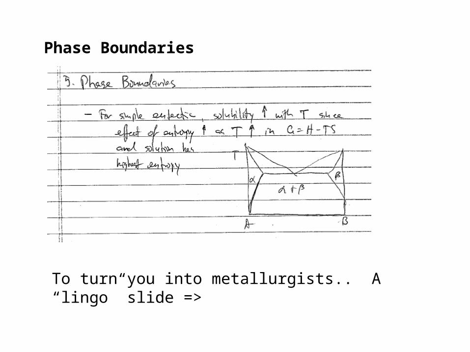
Phase Boundaries
To turn you into metallurgists.. A “lingo” slide =>
The idea that the solid solubility always increases with temperature (because temperature favors entropy) is true for almost all systems but fails at high temperatures in a technically very important system:
Dopants in Silicon
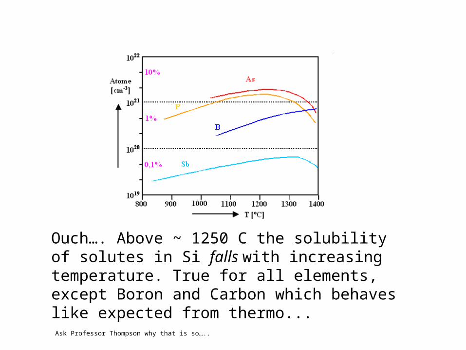
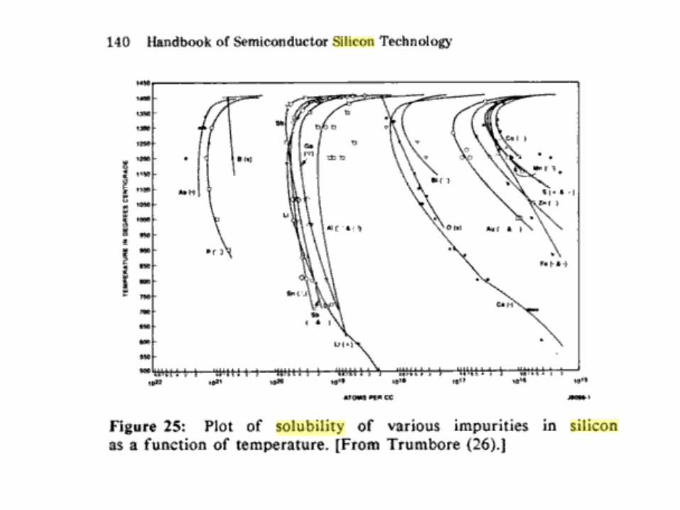
Ouch…. Above ~ 1250 C the solubility of solutes in Si falls with increasing temperature. True for all elements, except Boron and Carbon which behaves like expected from thermo...
Ask Professor Thompson why that is so…..
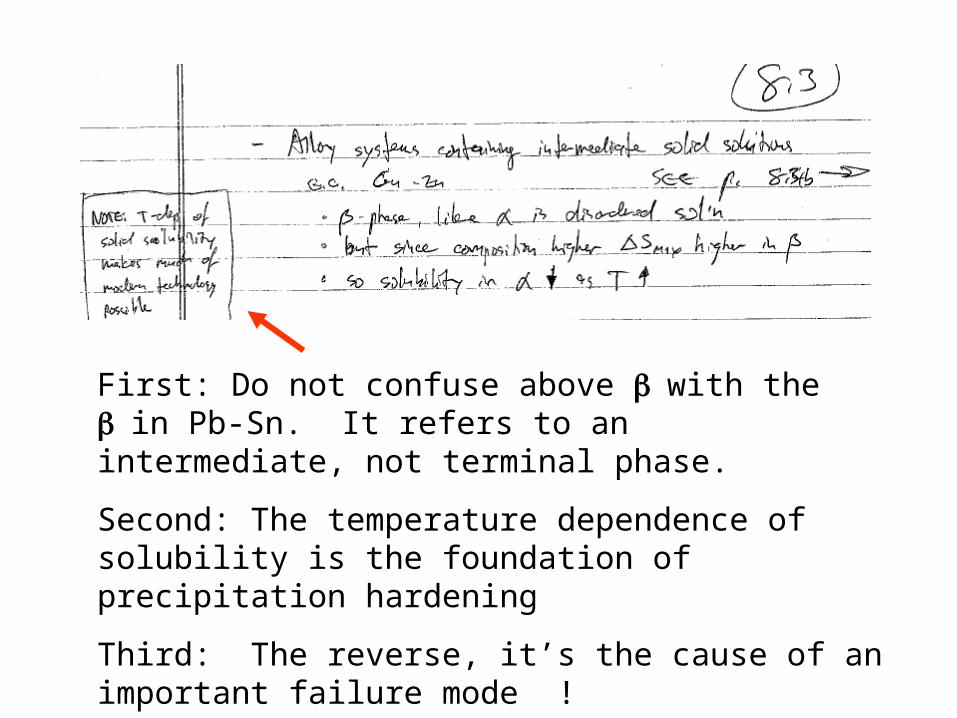
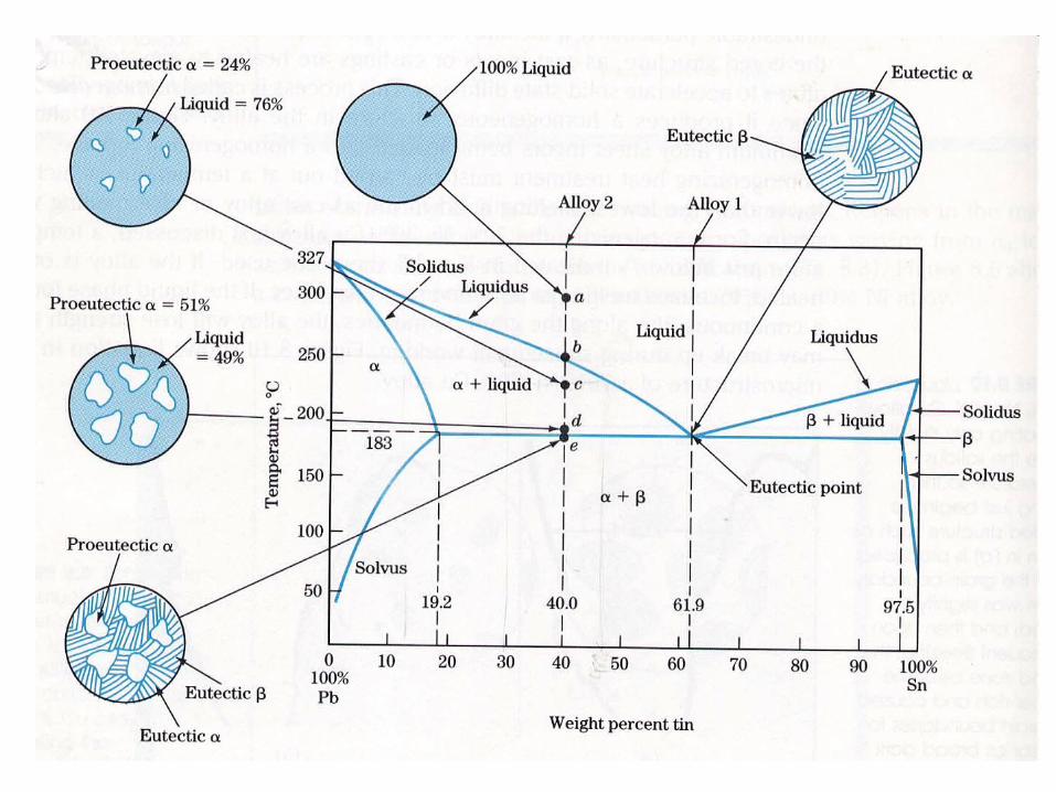
First: Do not confuse above with the in Pb-Sn. It refers to an intermediate, not terminal phase.
Second: The temperature dependence of solubility is the foundation of precipitation hardening
Third: The reverse, it’s the cause of an important failure mode !
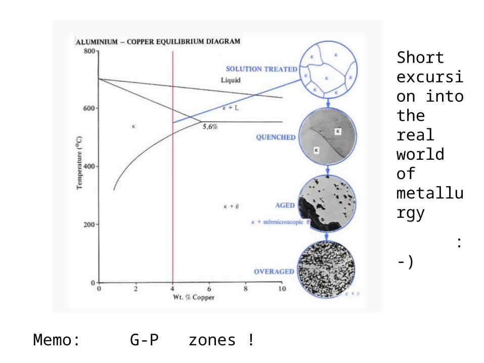
Memo: G-P zones !
Short excursion into the real world of metallurgy
:-)
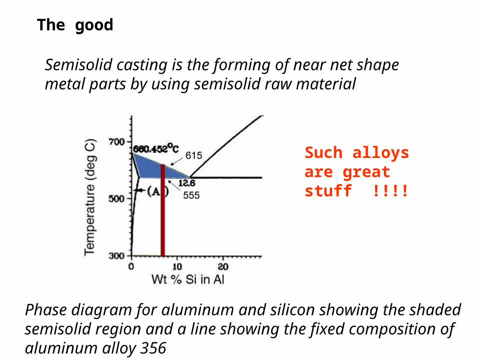
The good
Semisolid casting is the forming of near net shape metal parts by using semisolid raw material
Phase diagram for aluminum and silicon showing the shaded semisolid region and a line showing the fixed composition of aluminum alloy 356
Such alloys are great stuff !!!!
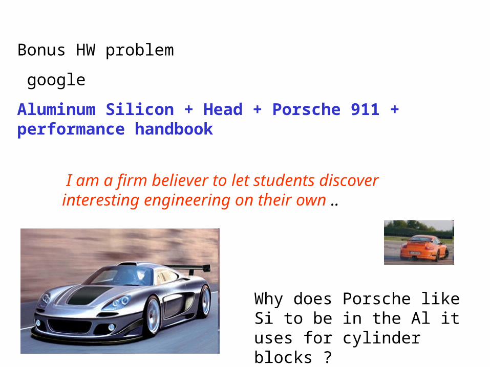
Bonus HW problem
Aluminum Silicon + Head + Porsche 911 + performance handbook
I am a firm believer to let students discover interesting engineering on their own ..
Why does Porsche like Si to be in the Al it uses for cylinder blocks ?
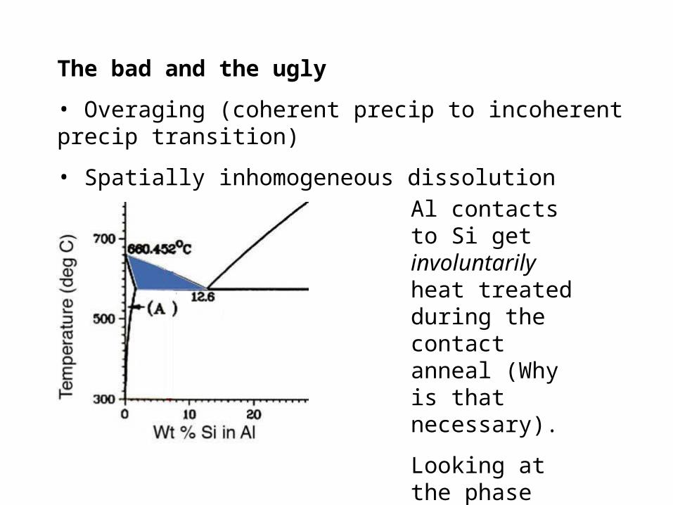
The bad and the ugly
• Overaging (coherent precip to incoherent precip transition)
• Spatially inhomogeneous dissolution
Al contacts to Si get involuntarily heat treated during the contact anneal (Why is that necessary).
Looking at the phase diagram, would you worry ?
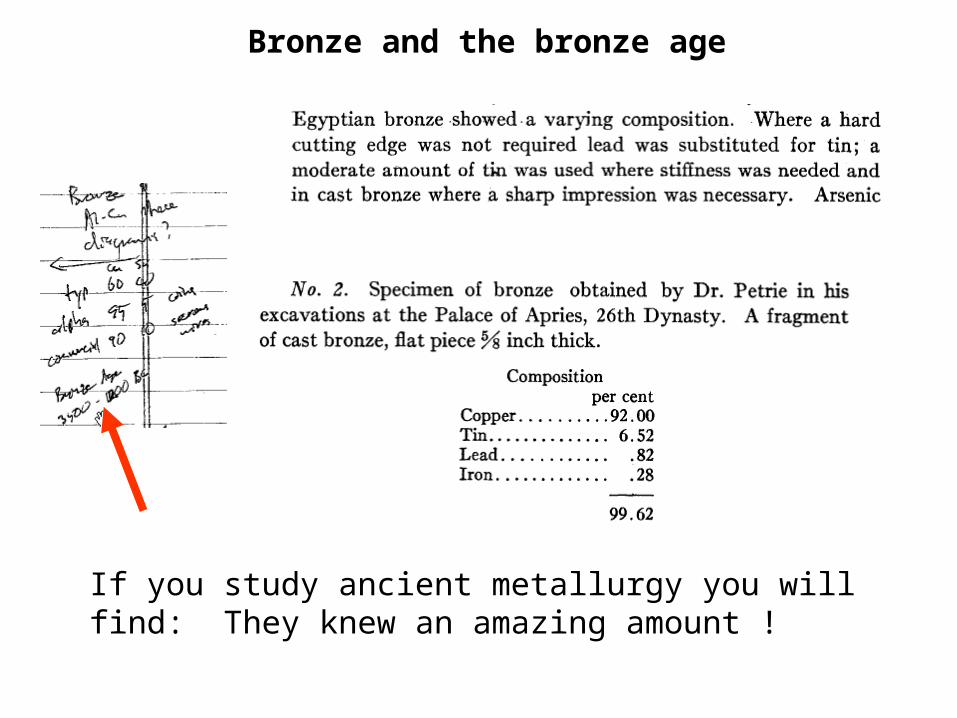
If you study ancient metallurgy you will find: They knew an amazing amount !
Bronze and the bronze age
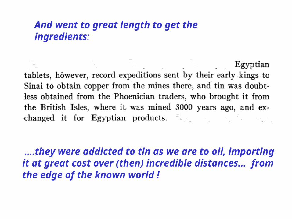
….they were addicted to tin as we are to oil, importing it at great cost over (then) incredible distances… from the edge of the known world !
And went to great length to get the ingredients:
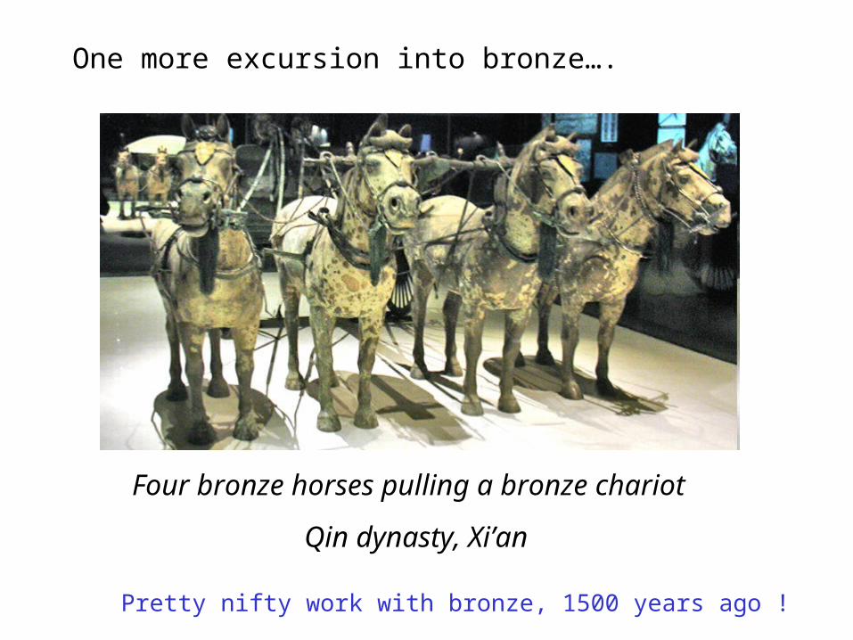
One more excursion into bronze….
Four bronze horses pulling a bronze chariot
Qin dynasty, Xi’an
Pretty nifty work with bronze, 1500 years ago !
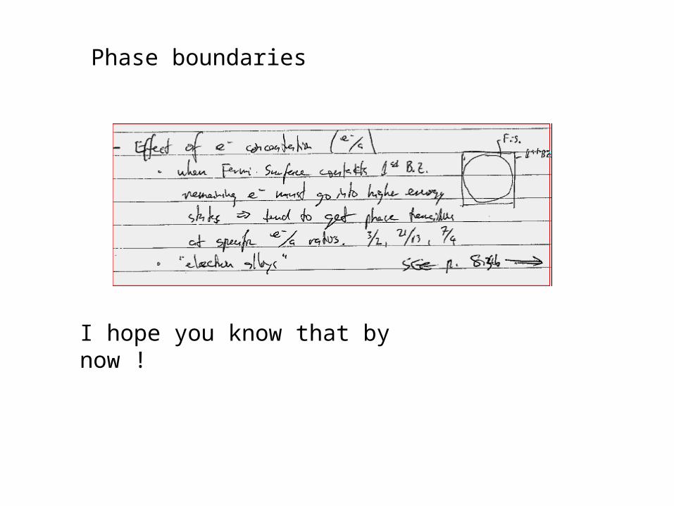
I hope you know that by now !
Phase boundaries
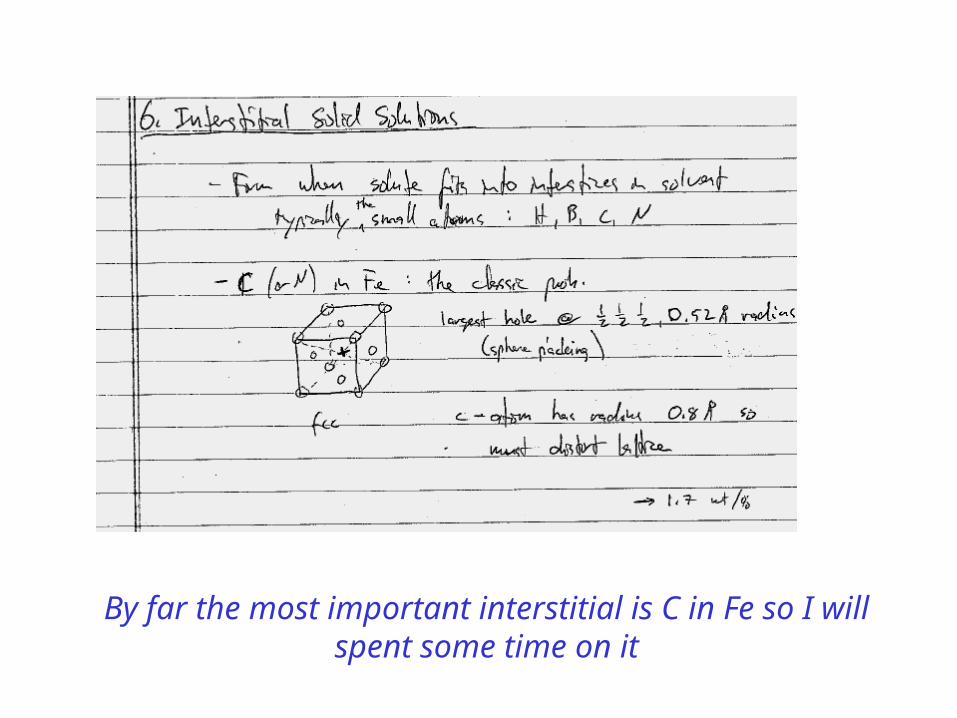
By far the most important interstitial is C in Fe so I will spent some time on it
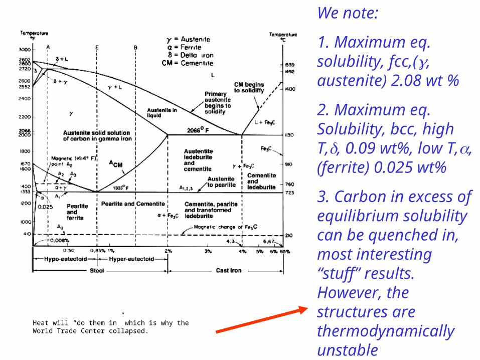
We note:
1. Maximum eq. solubility, fcc,(, austenite) 2.08 wt %
2. Maximum eq. Solubility, bcc, high T,, 0.09 wt%, low T,, (ferrite) 0.025 wt%
3. Carbon in excess of equilibrium solubility can be quenched in, most interesting “stuff” results. However, the structures are thermodynamically unstable
Heat will “do them in” which is why the World Trade Center collapsed.
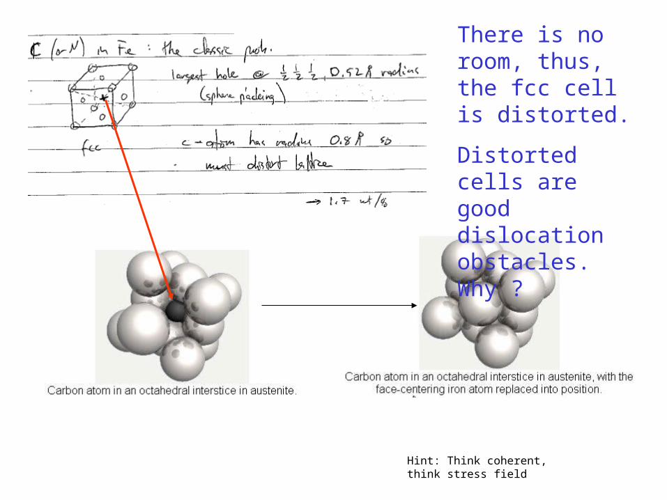
There is no room, thus, the fcc cell is distorted.
Distorted cells are good dislocation obstacles. Why ?
Hint: Think coherent, think stress field
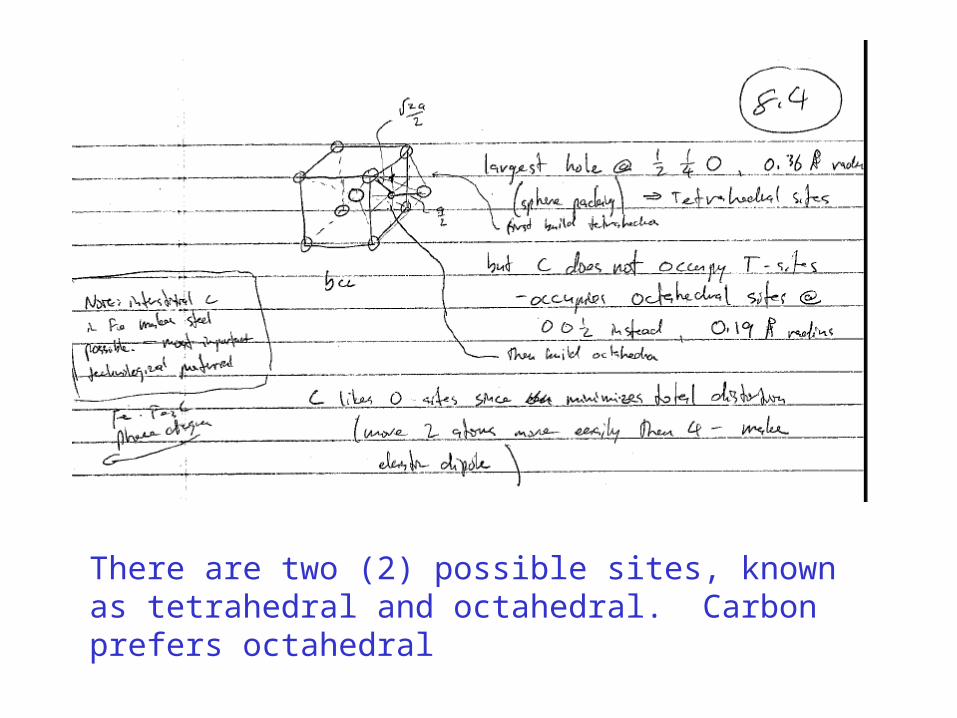
There are two (2) possible sites, known as tetrahedral and octahedral. Carbon prefers octahedral
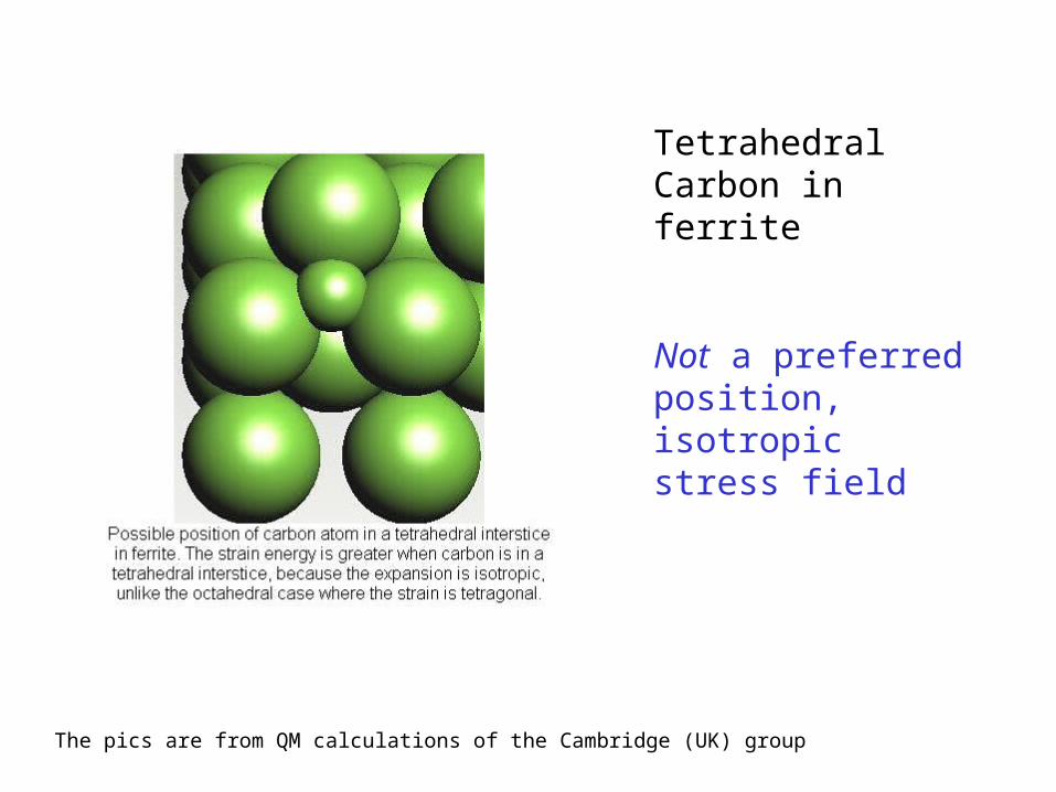
The pics are from QM calculations of the Cambridge (UK) group
Tetrahedral Carbon in ferrite
Not a preferred position, isotropic stress field
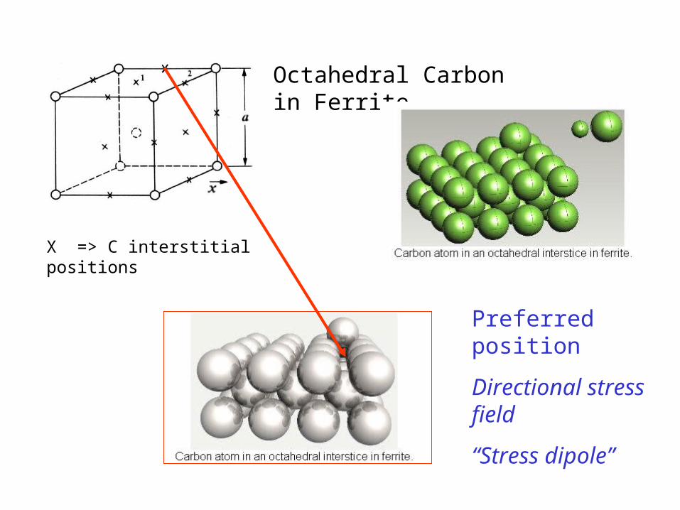
X => C interstitial positions
Octahedral Carbon in Ferrite
Preferred position
Directional stress field
“Stress dipole”
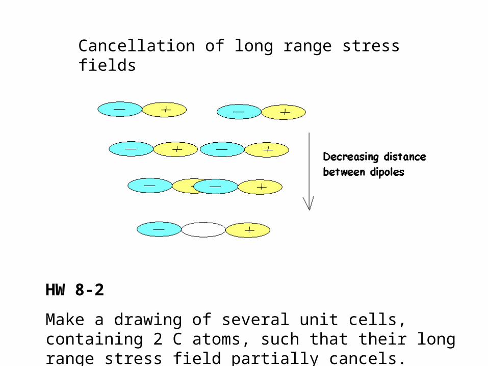
Cancellation of long range stress fields
HW 8-2
Make a drawing of several unit cells, containing 2 C atoms, such that their long range stress field partially cancels.
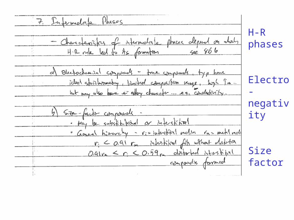
H-R phases
Electro-negativity
Size factor
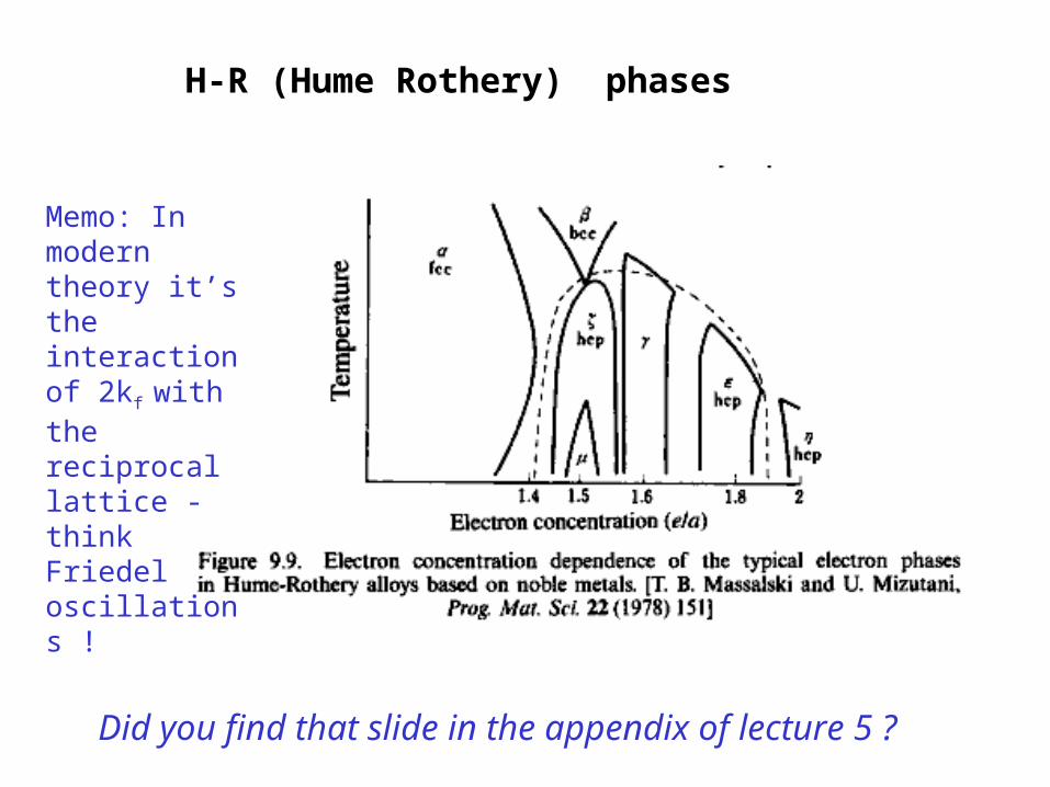
H-R (Hume Rothery) phases
Did you find that slide in the appendix of lecture 5 ?
Memo: In modern theory it’s the interaction of 2kf
with the reciprocal lattice - think Friedel oscillations !
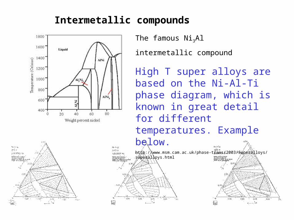
The famous Ni3Al
intermetallic compound
Intermetallic compounds
High T super alloys are based on the Ni-Al-Ti phase diagram, which is known in great detail for different temperatures. Example below.http://www.msm.cam.ac.uk/phase-trans/2003/Superalloys/superalloys.html
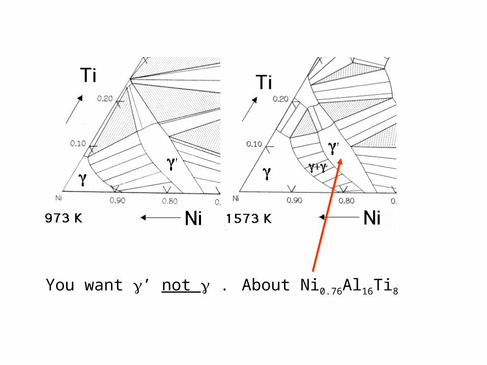
You want ’ not . About Ni0.76Al16Ti8
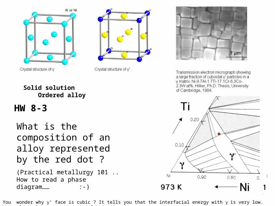
HW 8-3
What is the composition of an alloy represented by the red dot ?(Practical metallurgy 101 .. How to read a phase diagram…… :-)
Solid solution Ordered alloy
You wonder why ’ face is cubic ? It tells you that the interfacial energy with is very low. That also helps to suppress Oswald ripening
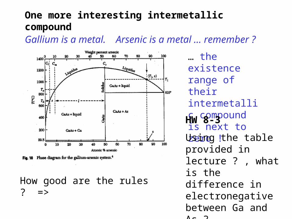
Gallium is a metal. Arsenic is a metal … remember ?
… the existence range of their intermetallic compound is next to zero !
HW 8-3
Using the table provided in lecture ? , what is the difference in electronegative between Ga and As ?
What is it between Ni and Al ?
One more interesting intermetallic compound
How good are the rules ? =>
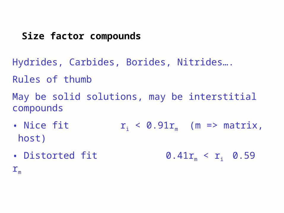
Size factor compounds
Hydrides, Carbides, Borides, Nitrides….
Rules of thumb
May be solid solutions, may be interstitial compounds
• Nice fit ri < 0.91rm (m => matrix, host)
• Distorted fit 0.41rm < ri 0.59 rm
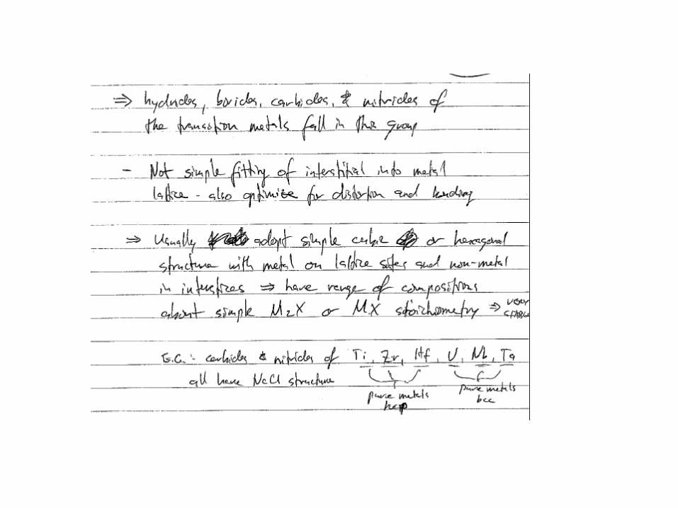
I have a slightly different view why the transition metal carbides, borides tend to be cubic
• The transition metals easily give up electrons
• Carbon, Boron want electrons to fill their shell
=> Strong ionic component
• Ionic compounds are cubic
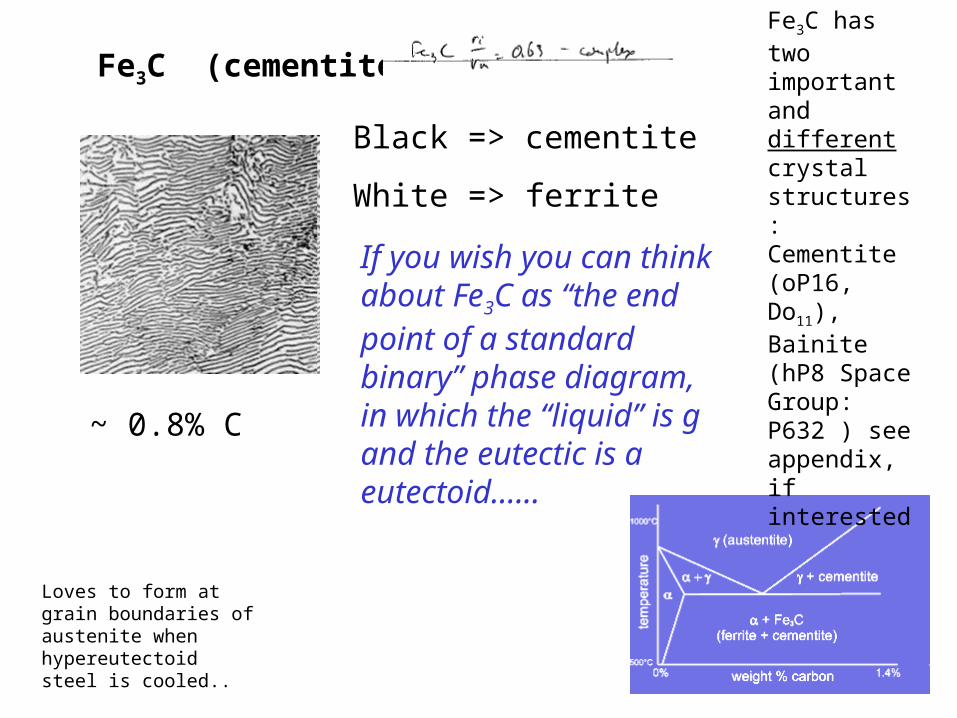
Fe3C (cementite)
Black => cementite
White => ferrite
~ 0.8% C
If you wish you can think about Fe3C as “the end point of a standard binary” phase diagram, in which the “liquid” is g and the eutectic is a eutectoid…...
Loves to form at grain boundaries of austenite when hypereutectoid steel is cooled..
Fe3C has two important and different crystal structures: Cementite (oP16, Do11), Bainite (hP8 Space Group: P632 ) see appendix, if interested
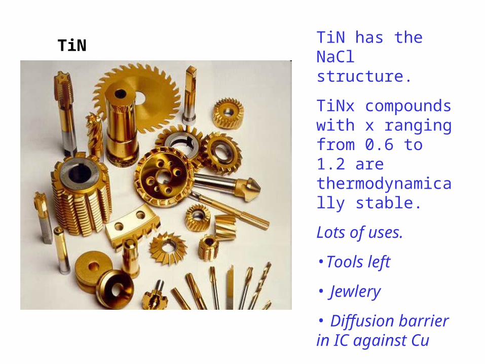
TiN TiN has the NaCl structure.
TiNx compounds with x ranging from 0.6 to 1.2 are thermodynamically stable.
Lots of uses.
•Tools left
• Jewlery
• Diffusion barrier in IC against Cu
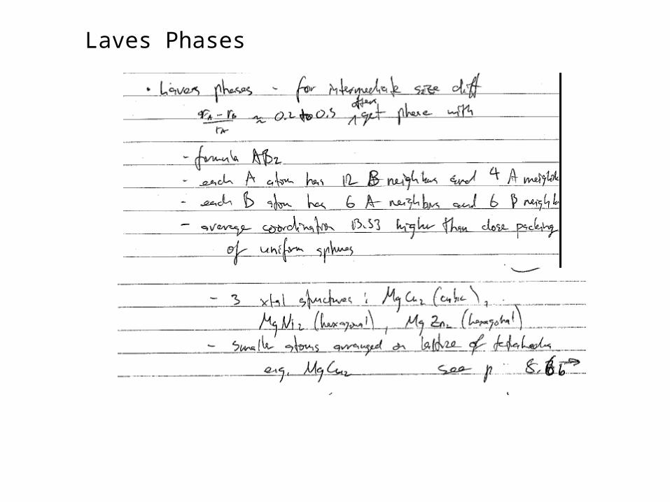
Laves Phases
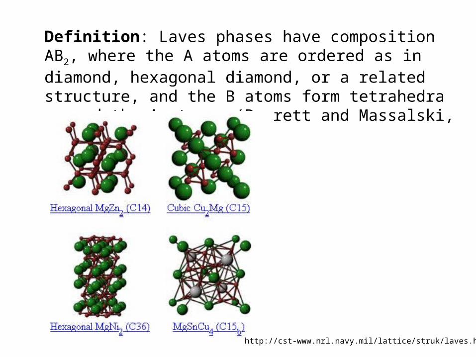
Definition: Laves phases have composition AB2, where the A atoms are ordered as in diamond, hexagonal diamond, or a related structure, and the B atoms form tetrahedra around the A atoms. (Barrett and Massalski, pp. 256-9),
http://cst-www.nrl.navy.mil/lattice/struk/laves.html
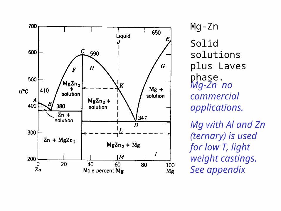
Mg-Zn
Solid solutions plus Laves phase.
Mg-Zn no commercial applications.
Mg with Al and Zn (ternary) is used for low T, light weight castings. See appendix
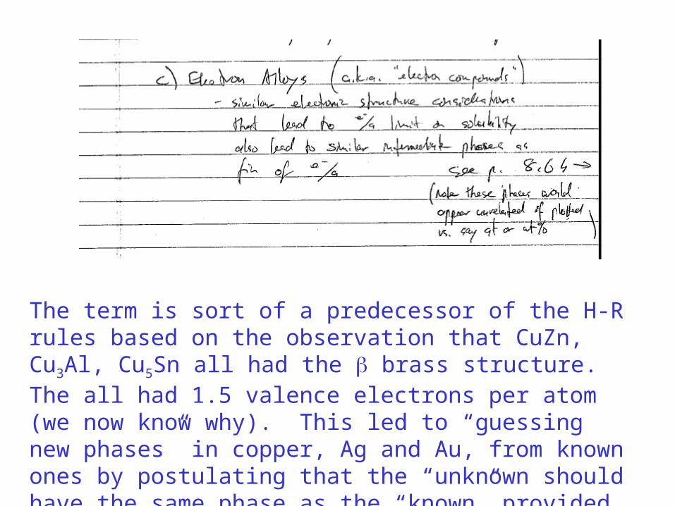
The term is sort of a predecessor of the H-R rules based on the observation that CuZn, Cu3Al, Cu5Sn all had the brass structure. The all had 1.5 valence electrons per atom (we now know why). This led to “guessing new phases” in copper, Ag and Au, from known ones by postulating that the “unknown should have the same phase as the “known” provided it had the same e-/atom ratio. That led the term “electronic phase” and “electronic compound”
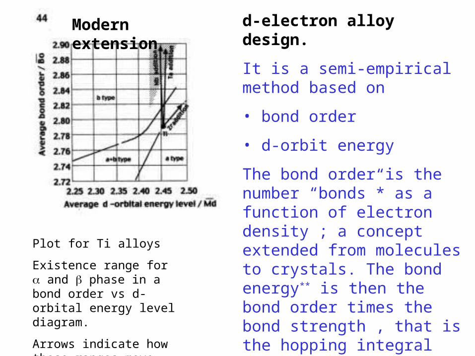
d-electron alloy design.
It is a semi-empirical method based on
• bond order
• d-orbit energy
The bond order is the number “bonds”* as a function of electron density ; a concept extended from molecules to crystals. The bond energy** is then the bond order times the bond strength , that is the hopping integral * in a H2 molecule the bond order 0 if you have o electrons for the two protons, 0.5 if you have only 1 electron for the two protons,, 1 if you have 2 electrons for the two protons, 0.5 if you force 3 electrons in (one is now antibonding) and 0 if you force in four electrons.
** a factor 2 too tedious to explain here
Plot for Ti alloys
Existence range for and phase in a bond order vs d-orbital energy level diagram.
Arrows indicate how these ranges move with alloying
Modern extension

The End
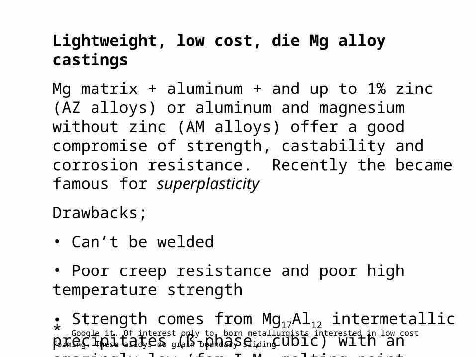
Lightweight, low cost, die Mg alloy castings
Mg matrix + aluminum + and up to 1% zinc (AZ alloys) or aluminum and magnesium without zinc (AM alloys) offer a good compromise of strength, castability and corrosion resistance. Recently the became famous for superplasticity
Drawbacks;
• Can’t be welded
• Poor creep resistance and poor high temperature strength
• Strength comes from Mg17Al12 intermetallic precipitates (ß-phase, cubic) with an amazingly low (for I.M. melting point (462° C.)
* Google it. Of interest only to born metallurgists interested in low cost forming. These alloys do grain boundary sliding
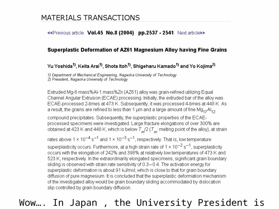
Wow…. In Japan , the University President is a co-author !!!!
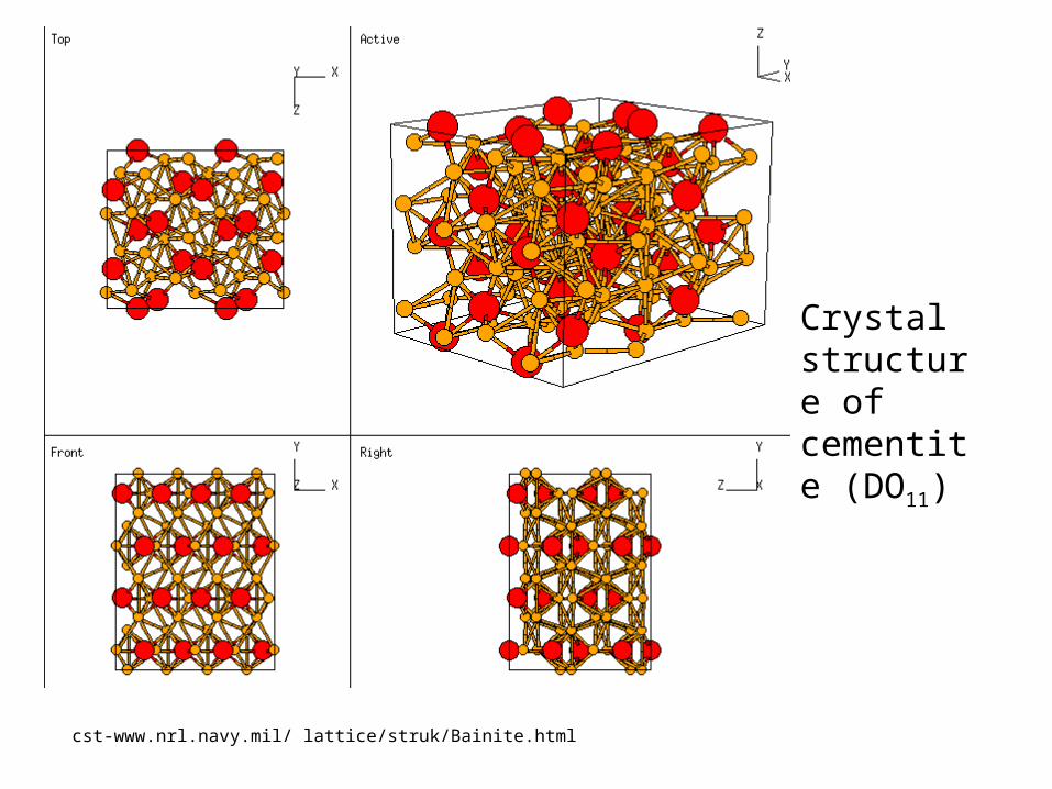
Crystal structure of cementite (DO11)
cst-www.nrl.navy.mil/ lattice/struk/Bainite.html
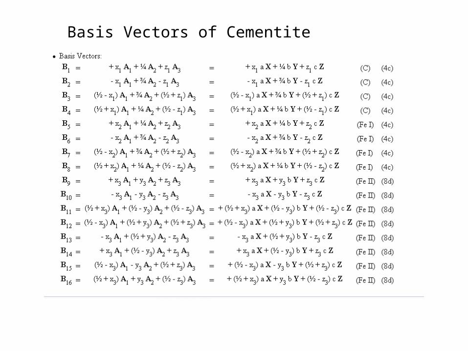
Basis Vectors of Cementite
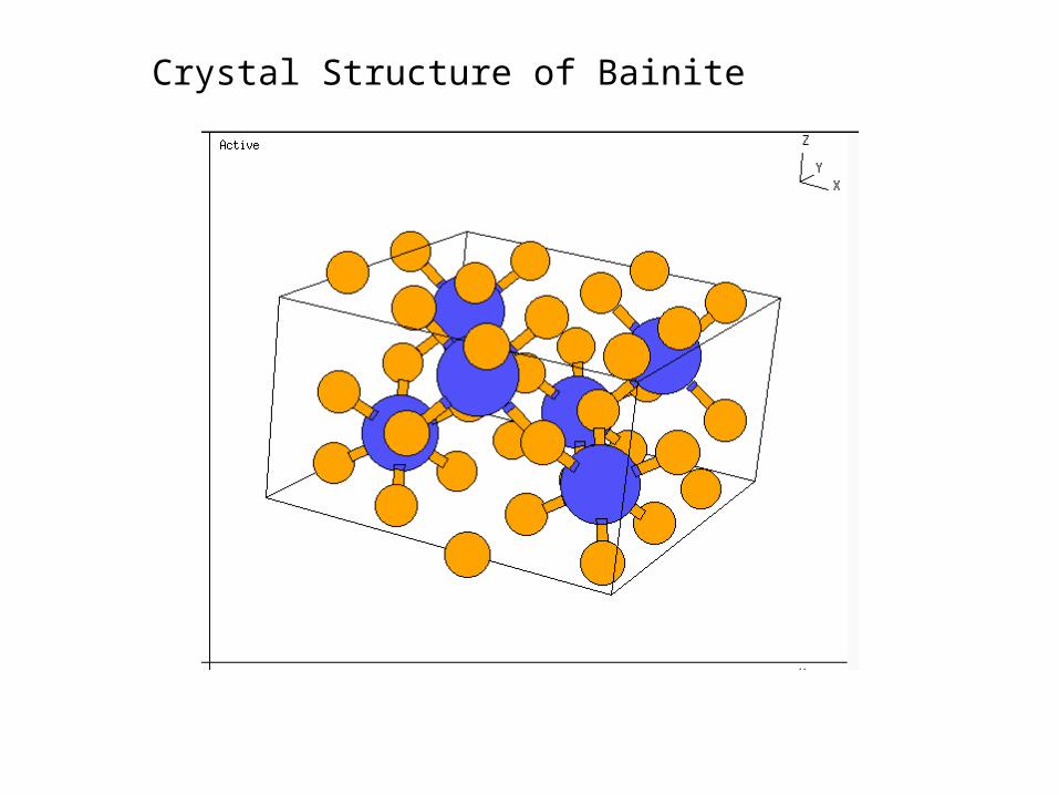
Crystal Structure of Bainite
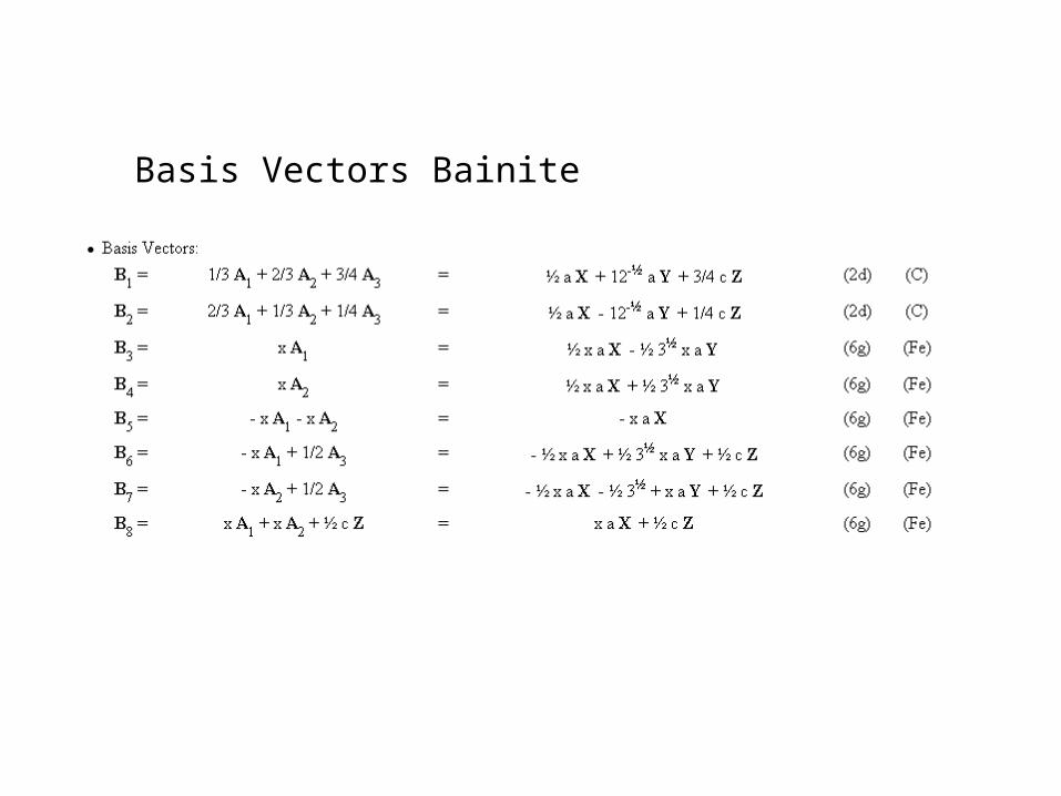
Basis Vectors Bainite