physical mechanisms and mathematical models of bead ... · physical mechanisms and mathematical...
TRANSCRIPT

11
Physical Mechanisms and Mathematical Models
of Bead Defects Formation During Arc Welding
Wladislav Sudnik R & E Center ‘ComHi-Tech in Materials Joining‘
Welding Department, Tula State University, Russian Federation
1. Introduction
An increase in the productivity of arc welding is connected with an increase in both welding
speed and welding current, which leads to the formation of welding defects, such as
undercuts, humps, burn-through areas, etc. Fusion welding defects is classified due to the
international standard ISO 6520-1.
In most cases mathematical models of weld formation describe the normal course of the
process and establish the relation between welding parameters and weld pool sizes. It is
much more difficult to construct the models which describe defective weld formation; the
formation of the defects is described within the limits of the general model of the process at
some combinations of welding parameters and weld pool sizes.
The arc pressure at the crater of a weld pool makes considerable impact on the basic
processes occurring during the weld formation. Despite the arc pressure it is not a direct
welding parameter, it has an important technological value as it defines the crater depth of a
weld pool and essentially the lack of penetration and an incomplete fusion (Yamauchi et al.,
1982). Free surface deformation of a molten weld pool is an important feature of fusion
welding. For gas tungsten arc welding (GTAW), a significant weld pool deformation may
take place at high current levels. In gas metal arc welding (GMAW), the free surface
problem is more complicated due to the filler metal addition and droplet impact. Free
surface deformation affects the fluid flow and heat transfer in the weld pool, which, in turn,
affects the weld geometry. The first profound research on the formation of weld defects was
made by Bradstreet, 1968, in which the basic mechanisms of the formation of weld defects
were shown in fusion welding.
The first two decades of the 70s and 80s of the 20th century have been devoted to the
research of the mechanisms of the formation of undercuts and the causes of the transition
from a normal mode of the weld formation to that one with the appearance of defects, as
well as to the creation of the correspondent mathematical models. Selected papers of that
period are presented in Table 1.
www.intechopen.com

Arc Welding
244
Bradstreet, 1968 Effect of surface tension and melt flow on weld bead formation
Paton et al., 1971 Hypothesis of a weld pool hydraulic head and arc pressure balance, arc induced undercutting
Erokhin et al., 1972 Hypothesis of a level lowering of a weld pool and its fixation by solidification process
Yamamoto & Shimada, 1975 Hypothesis of a hydraulic jump and undercut bead, supercritical flow model
Nomura et al., 1982 Experimental confirmation of hypothesis validity Paton et al., 1971
Sudnik, 1985, 1991a, b
Mathematical modelling of solidified free surface profile in fusion welding. For the first time, undercutting had been modelled and simulated
Table 1. Selected papers of research on the mechanisms of the formation of undercuts.
For the last 20 years the mechanisms of the humps formation have been actively studied, and corresponding mathematical models have been developed, Table 2.
Tytkin, 1981 Theoretical study of coarse flaky surface. Kelvin-Helmholtz instability
Gratzke et al., 1992 Capillary instability model for humping
Lin & Eagar, 1983 Explained humping using vortex theory
Mendez & Eagar, 2003 Simple model for force balance between the gouged region and trailing region inside weld pool
Nguyen et al., 2005, 2006
Experimental study of hump formation by the instrumentality of LaserStrobe video imaging system; hump bead as a series of periodic fluctuation of swellings is one of dominating defect in high speed welding
Soderstrom & Mendez, 2006
Two types of humping formation: gouging region and beaded cylinder
Kumar & DebRoy, 2006 Unified mathematical model of humping in GTAW with Kelvin-Helmholtz instability
Cho & Farson, 2007 Thermohydrodynamic mathematical model and numeric analysis of hybrid process for prevention of weld bead hump formation
Chen & Wu, 2009 Thermohydrostatic mathematical model and numerical analysis of forming mechanism of hump bead in high speed GMAW
Table 2. Selected papers on the study of the humps formation and the creation of the correspondent models.
From a mathematical viewpoint, the modelling of the weld defects formation consists in simulation of the solidifying profile of the weld free surface. It demands the execution of numerical three-dimensional modelling of a weld pool with the deformable free surface,
www.intechopen.com
Physical Mechanisms and Mathematical Models of Bead Defects Formation During Arc Welding
245
which for the first time had been executed by Sudnik, 1985, 1991 at predicting the quality of welds and simulation of the undercuts formation in GTAW. Then the first numerical thermohydrostatic mathematical models for GTAW with a deformable weld pool surface were created by Ohji et al., 1983, and Zacharia et al., 1988. In the 21st century there were developed fuller thermohydrodynamic models by Kumar and DebRoy, 2006; Cho and Farson, 2007, as well as the simplified thermohydrostatic models by Chen & Wu, 2009 for the simulation of the humps formation. The purpose of the present work is the analysis of the physical mechanisms of the defects formation on the basis of the full and simplified mathematical models of the formation of undercuts and humps. The ways of thermohydrodynamic and thermohydrostatic modelling and simulation of the weld formation with correspondent equations and their boundary conditions will be presented. There will be stated the stready state mathematical models of the GTAW and GMAW processes, as well as the transient model for the GMAW processes that allows the reproduction of the formation of undercuts and burn-through areas. The task of the search for the welding parameters, providing faultless areas, will be illustrated on the examples of two-dimensional areas for GTAW- and three-dimensional areas for GMAW-processes.
2. Physical mechanisms of defects formation
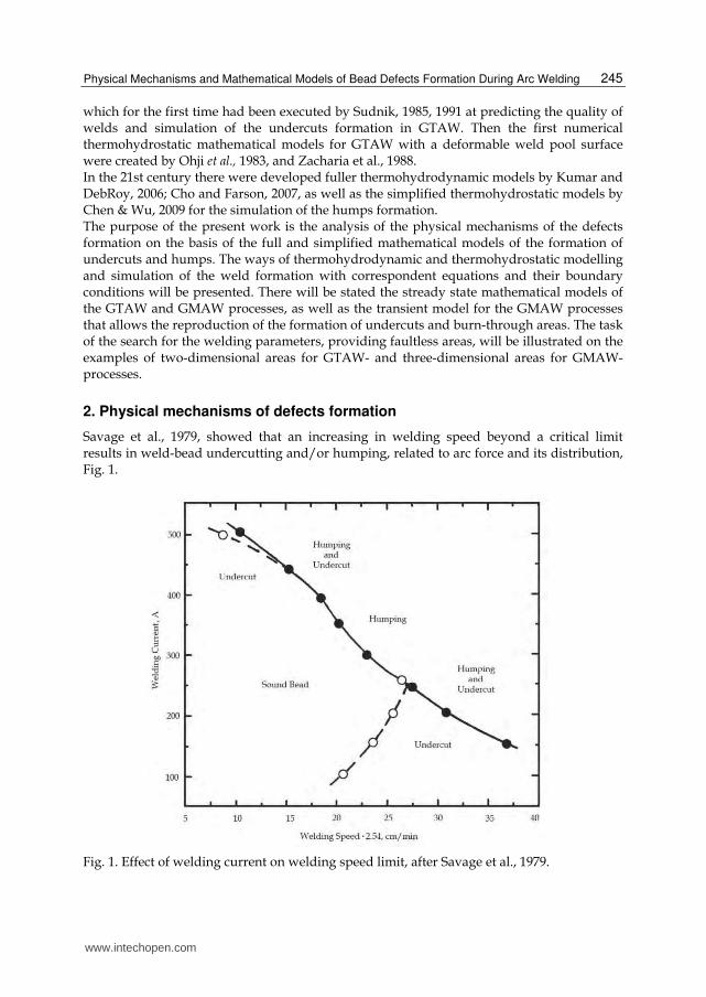
Savage et al., 1979, showed that an increasing in welding speed beyond a critical limit results in weld-bead undercutting and/or humping, related to arc force and its distribution, Fig. 1.
Fig. 1. Effect of welding current on welding speed limit, after Savage et al., 1979.
www.intechopen.com

Arc Welding
246
According to the results of this work there are some characteristic ranges of the weld current for the formation of undercuts and humps. For the currents below 250 А, critical welding speed corresponds to the beginning of formation of undercuts, and for the formation of humps higher speeds are required. In the range 250 - 400 А the speed limit corresponds to the beginning of the humps formation without undercuts. For the currents above 400-430 А, at first an undercut forms, whereas further increase in the welding speed leads to the humps.
2.1 Undercutting mechanisms Bradstreet, 1968, used a high speed camera to observe undercutting and humping phenomena and showed that the undercutting is also strongly influenced by surface tension, which controls wetting at the edges of the weld pool. Paton et al., 1971, put forward a hypothesis about a weld pool hydraulic head and arc pressure balance. At an increase in the welding speed, the pressure at the weld pool bottom from a liquid column decreases at the constancy of the arc pressure, and at balance infringement probably formation of an undercut occurs. This hypothesis has been confirmed by Nomura et al., 1982 which have experimentally confirmed the justice of this hypothesis. Erokhin et al., 1972 put forward hypothesis of the level lowering of the weld pool and its fixation by the solidification process. Authors also considered that level of the liquid metal in the points of the maximal width of the weld pool where solidification at the weld edges begins, it appears below the surface of the basic metal owing to the big inclination of the weld pool mirror and the high speed of solidification. Chernyshov et al., 1979 considered that undercuts and other defects initiate difficult wave processes at the surface of the liquid metal and, in particular, hydraulic jumps of various forms. The hydraulic jump is known from hydraulics and is characterised by a spasmodic increase in height of the liquid level. The hypothesis (Yamamoto & Shimada, 1975; Shimada & Hoshinouchi, 1982) about the role of the hydraulic jump in the formation of welding defects, including the bead undercut has been undeservedly forgotten, Fig. 2. They connect the occurrence of undercuts, first of all, with the arc pressure; therefore the aspiration to receive a smaller arc pressure has in their researches caused application of a welding process in the environment of inert gas of the lowered pressure (32 mm Hg). They have established that in comparison with welding at atmospheric pressure normal formation of the platen without undercuts can be received in wider range and at higher values of the weld current and the welding speed. At an increase in the welding speed instead of the normal wide platen there is a narrow deep platen, and on the front wall of a weld pool there is an area gouging. At excess of critical speed of formation of undercuts the area gouging extends on all a crater zone of a weld pool and reaches it midlength section. Thus liquid metal is displaced in a tail part of a weld pool with undercut formation at solidification of liquid metal. Sudnik, 1985, 1991 developed a mathematical model of the weld formation in GTAW which, for the first time, allowed to model and to reproduce the undercut. The mathematical model of fusion welding process by Sudnik, 1991a, considered the energy equation in enthalpy statement and the equation of balance of pressure on deformable free surfaces of the weld pool at the full penetration with boundary conditions corresponding to the weld process. It has appeared that the undercut is one of natural forms of cross-section and arises at the fusion line at a level lowering of the surface of a weld pool on the sites of the beginning of the solidification.
www.intechopen.com

Physical Mechanisms and Mathematical Models of Bead Defects Formation During Arc Welding
247
Fig. 2. Model of hydraulic jump and gouging region, after Shimada and Hoshinouchi, 1982
Ohji et al, 2004 presented a three-dimensional transient mathematical model of the GMAW- process for simulation of multiple pass welding and welding of fillet welds with cross-section fluctuations of the torch which also reproduces undercut formation.
2.2 Humping mechanisms Bradstreet, 1968 is credited with publishing the first paper to directly recognise humping during GMAW. He has established that the hump defect was observed only at a high travel speed, that a leading (“push”) weld gun travel angle suppressed hump formation, and that oxygen in the shielding gas exacerbated hump formation. He proposed a liquid instability theory that was later modified by Gratzke et al., 1992 explaining humping during GMAW. Yamamoto and Shimada, 1975 and Shimada and Hoshinouchi, 1982 used the theory of hydraulic jump to account not only for an undercut, but also for the humping phenomenon, Fig. 3. Mendez and Eagar, 2003 offered an explanation of a penetration and occurrence of defects in a weld pool at high currents. Thus arc pressure pushes the fused metal to a back part of a weld pool, creating under an arc a thin layer of liquid metal. Premature solidification of this thin layer initiates formation of the humps, the split pool, parallel formation of humps, tunnel porosity and an undercut. The thin nature of a liquid layer is the reason of the increased penetration at a high current. They proposed a simple model for force balance between the gouged region and trailing region inside weld pool. Later, Soderstrom and Mendez, 2006 have offered two types of humping formation: gouging region and beaded cylinder. Nguyen et al., 2005, 2006 have lead an experimental study of hump formation by
www.intechopen.com

Arc Welding
248
the instrumentality of LaserStrobe video imaging system and have shown that hump bead as a series of periodic fluctuation of swellings is one of the dominating defects in high speed welding. Cao et al., 2004 used a commercial software package, FLOW-3D, to simulate a transient moving weld pool under the impact of droplet impingement without the droplet generation. Choi et al., 2006 investigated hybrid processes of welding by the laser and GMAW for suppression of formation of humps and have shown that the heat input from the defocused laser beam applied in front of a GMAW pool suppresses formation of a weld bead hump defects. Kumar and DebRoy, 2006 have proposed the unified three-dimensional thermohydrodynamic mathematical model of humping defects in GTAW based on the Kelvin-Helmholtz instability of a free surface. This model can be used to help prevent humping when the effect of arc current, welding speed, shielding gas, electrode geometry, ambient pressure, torch angle, and external magnetic field are considered. Hu et al., 2007 studied weld pool dynamics under the periodical impingement of filler droplets and the formation of such defects as ripples. Cho and Farson, 2007 used a mathematical model of hybrid process laser + pulsed GMA welding for the prevention of weld bead hump formation and have also established how formation of bead humps in high-speed GMAW is prevented by additional laser heat input. Chen and Wu, 2009 have developed a thermohydrostatic mathematical model and have lead numerical analysis of forming mechanism of hump bead in high speed GMA welding.
3. Mathematical models of the formation of weld and bead defects
Generally anisothermic movement of a viscous compressed liquid in hydrodynamics is described by the system of the Navier-Stockes-Fourier equations that include.
Three equations of Navier-Stokes (for a component of a velocity vector u, v, w).
The continuity equation (for pressure p).
The equation of convective heat conductivity (for calculation of temperature T).
The equation of state which connects p, ρ, T (for ideal gases this equation is of the form p = ρ RT).
Thus, there are 6 equations with 6 unknown (u, v, w, ρ, T, p). This system is extremely difficult to solve even with the use of modern numerical methods on powerful personal computers. Therefore, often one should examine various simplifications of this system which in some cases adequately model a fluid flow. The boundary problem for a concrete thermal and hydrodynamic process of fusion welding is formed by differential equations with initial and boundary conditions. The full formulation of this problem in scientific weld literature is absent. We will make an attempt to examine these questions with reference to arc welding and defects of a weld. The weld pool model can be described by the three main conservation equations of energy, movement and continuity (Rykalin et al., 1985) with the boundary conditions defining interaction of heat and force flows with welded workpiece. The order of the record of the differential equations of impulse (movement), continuity and energy (a convective heat transfer) accepted in hydrodynamics, from the point of view of mathematical physics and the numerical iterative solution by the computer, does not play a special role, as the solution of the coupled problem is reached iteratively. For high-temperature weld processes the first-priority solution of the energy equation in most cases is defining and sets the melt volume and its form where hydrodynamic processes proceed.
www.intechopen.com

Physical Mechanisms and Mathematical Models of Bead Defects Formation During Arc Welding
249
3.1 Model of convective heat transfer and viscous fluid flow dynamics 3.1.1 Energy equation, or the equation of a convective heat transfer The weld pool model according to Rykalin et al., 1985 is described by conservation equations of energy, movement after Navier-Stokes and continuity. The energy equation with a moving heat source can be presented as the equation of heat conductivity in enthalpy statement with a fluid flow (Kou & Sun, 1985)
w
H HuH v T
t x
(1)
where ρ is the density, is an enthalpy coupled with temperature Т by relation , where , with c is thermal capacity, ψl is a fraction of a liquid phase in two-phase zone of solid-liquid melting / solidification area, ; Tl and Ts are liquidus and solidus temperatures, is the latent heat of melted alloy, is a flow velocity vector of a weld pool melt, vw is the welding speed, and λ is heat conductivity coefficient.
3.1.2 Thermal boundary conditions The boundary condition on the top surface describes the energy source heat flows and heat sinks on an air convection, radiation and evaporation
2
4 40 0 vap2 2
q
exp ( ) ( )2 2q
T Q rT T T T q
t k k
(2)
where η is the process efficiency, Q is the heat source power, kq is heat flow concentration coefficient. Α is the heat exchange-coefficient, σ is the Stefan-Boltzmann constant, ε is the emissivity, qvap is the heat sink on evaporation.
3.1.3 Movement conservation equation for a viscous liquid The movement conservation equation for a viscous incompressible Newtonian liquid in Navier-Stokes approximation is presented according to Landau and Lifshiz, 1959
2( )u
u u p u gt
(3)
where p is the pressure, is the viscosity, is the acceleration vector of free fall. In this equation the left part describes inertial force, including local and convective acceleration. In the right part there is a pressure gradient, a friction force and elevating force of a free convection.
3.1.4 Force boundary conditions Boundary conditions for a free surface may be of two types: kinematic, setting speeds on liquid boundaries, and dynamic, connected with pressure. Other boundary conditions for the walls of a weld pool are similar to hydrodynamic conditions on channel walls, i.e. to adhesion conditions according to which normal and tangential components of speed on a wall are equal to zero. The form of a free surface of a weld pool is defined from a condition of balance of internal and external forces on its surface. To avoid any formulations of this balance, we will make an attempt for its conclusion from the first principles.
www.intechopen.com

Arc Welding
250
Boundary conditions on a free interface a liquid - gas include: - normal stresses from pressure balance of a liquid and forces of a viscous friction (Landau and Lifshiz, 1959; Batchelor, 1970), and also it is similar from balance of capillary forces and forces of an arc pressure in the arc welding conditions, and, the left part of expression is written down like expression taking into account a viscous stress tensor
narc
1 2
1 12
up p
n R R (4)
- and tangential stresses of Marangoni forces
u T
n T z
(5)
where p is the pressure in a liquid on a free surface in a normal direction, µ is the dynamic viscosity of a melt, un is the velocity component of a fluid flow on a normal to a movement direction, γ is the surface tension, R1 and R2 are the main radiuses of curvature of the bent surface and parc is the arc pressure. For the approximate calculation of curvature of surface Z = Z (x, y), set in an explicit form, in hydrodynamics the formula of a Landau and Lifshits, 1959 is used
2
2
2
2
21
11
y
Z
x
Z
RR
which is fair for poorly bent surfaces. At the big surface deflections the multiplier of formulas of the differential geometry, equal to a cosine of an inclination of a surface of a weld pool is in addition used.
3.1.5 The continuity equation, or the mass conservation law The equation of continuity follows from the law of a mass conservation and registers
( ) 0div ut
(6)
This law of a mass conservation is important for modelling of a fusion welding process, including arc welding. At local heating there is a thermal expansion of metal and phase transformation during melting. Accepting an assumption about an immovability of solid boundary surfaces of a solidus and a constancy of mass of metal during heating and fusion (for example, during welding by a nonconsumable electrode), volume changes can be defined on the temperature change of density proportional to coefficient of expansion. The weld pool volume Vm, 0 with density ρ0 at reference temperature T0 and with dependence of density on temperature ρ (T) is equal to weld pool volume Vm with convexity at the expense of thermal expansion and phase transformation at melting. The convexity form of a melt is fixed at the front solidifications that define the form of a profile surface of a weld. The subsequent volume shrinkage and return thermal compression at cooling of solid metal reduce the sizes, not changing of convexity and concavity forms of area, for example, a weld undercut a little. The increase in volume of a weld pool because of a filler addition or its reduction because of a technological gap is considered by addition or reduction of these
www.intechopen.com

Physical Mechanisms and Mathematical Models of Bead Defects Formation During Arc Welding
251
volumes to volume Vm (Sudnik et al., 1999). The account of these phenomena defines an additional geometrical condition of change of volume, or balance of masses, in a welding zone
,0
0
m
,( )
mV V
dV Z x y dxdyT
(7)
The solution of the equations system (1) - (7) even on modern computers is connected with the big expenses of computer time. For example, for understanding of the humping formation during GMAW Cho & Farson, 2007 used software Flow3D which for reproduction of real-time 3 seconds has demanded expenses of almost 4 days of central processing unit time. Many simplified models are based on assumptions of weak changes of velocities and temperatures one direction under the relation with changes in other direction, for example, model of a boundary layer and other reduced Navier-Stokes equations.
3.2 Model of conductive heat transfer and inviscid fluid flow statics For simplification of a dynamic problem (1) - (7) 2 assumptions are accepted:
The fluid flow is accepted poorly convection, i.e. convection carrying over of heat to the fused metal is ignored,
The fused metal is a nonviscous incompressible liquid. It allows rejecting in the equations velocity terms who have less essential value for definition of behaviour of a weld pool which can be described by the theory of an ideal liquid of Euler.
3.2.1 Energy equation, or the equation of a conductive heat transfer The energy equation from moving with a welding speed vw a heat source in this case is represented by the usual equation of heat conductivity (without convection) in enthalpy statement
w
H Hv T
t x (8)
with the thermal boundary condition (2). At small velocities of movement of a source it is possible to neglect acceleration of a flow and viscosity of a melt, i.e. to sink inertial and viscous terms. From four basic driving forces of a fluid flow: gravity, pressure, friction and inertia remain only two: gravity and pressure which allow describing the phenomena in a weld pool under the hydrostatic law as the pressure created by a column of a liquid. Thus, three known conditions of a hydrostatics should be satisfied according Myshkis et al., 1987:
the Euler's condition in a weld pool volume,
the Laplace law (condition) on a melted free surface
the Dupre-Yuong condition on a contact line of three environments: a liquid - gas - solid body.
At balance the equation of continuity (6) becomes simpler (), that means, that a density field
is permanent.
The equation of Navier-Stokes (2) of fluid dynamics passes in Euler's condition, or the first
condition of a hydrostatics
www.intechopen.com

Arc Welding
252
,gp (9)
and the hydrodynamic boundary condition of normal stresses (4) becomes simpler and
takes the form the Laplace law, or the second condition of a hydrostatics
arcp
RRp
2
11
1
(10)
Integrating Euler's condition (7) where z is the height of a liquid column, we receive where
С is the arbitrary constant. This equality does not impose any restrictions on melt position,
and only defines pressure distribution in it. The Laplace’s law thus modified for weld
conditions (9) will play a role of the differential equation of a weld pool surface, and a
geometrical condition (7) - a role of a corresponding boundary condition.
3.2.2 Momentum conservation equation for a nonviscous liquid The modified equation of Laplace for conditions of fusion welding taking into account an arc pressure is of the form as
2 2 2 2 2
3/2 2 22 2 21 2
1 2 11 1exp
2 21 1
xx y yy x
p px y
Z Z ZxZyZxy Z ZZ F rgz C
R R k kZ Z Z
(11)
where Z = Z (x, y) is the free surface equation of the weld pool set in an explicit form in the
Cartesian system of co-ordinates x, y, z; the z is vertical coordinate of a deformable free weld
pool surface, Zx, Zy, Zxx, Zyy, Zxy are private derivative functions Z=Z (x, y) on
corresponding co-ordinates; F is force action of a source, the is concentration coefficient of
pressure and r is distance from an axis of a pressure source.
For calculation of curvature of a surface in hydrodynamics the formula for the first time
presented by Landau and Lifshits, 1959 is used. The constant С in the modified Laplace’s
equation (9) pays off from a condition satisfaction of an additional condition the continuity
equations (7). Mathematically, this constant C is the Lagrange multiplier in extreme
statement (Landau and Lifshiz, 1959; Kim and Na, 1999), and physically, the constant C
designates caused by surface deformation average change of pressure in a melt (Sudnik &
Erofeev, 1986; Radaj, 1999). Its value is defined from a boundary condition of a mass
conservation
3.2.3 Boundary condition The boundary condition (7) dynamic problems (1) - (7) does not change
m ,0
0,( )
mV V
Z x y dxdy dxdydzT
(7')
Thus, the equations of a weld pool surface in hydrostatic approximation, and taking into
account the equation of a conductive heat transfer (the energy equation) are formulated;
such model can be named a thermohydrostatic model of a weld pool.
www.intechopen.com

Physical Mechanisms and Mathematical Models of Bead Defects Formation During Arc Welding
253
3.3 Models of weld bead defects Defects of welded structures can be divided into two groups:
having the quantitative characteristic (width and depth of a penetration of a weld, depth and undercut radius, height of convexity or depth of concavity, etc.);
having qualitative character (presence of cracks, of pores, of burn-through etc.). Current values of the first defects pay off from the corresponding mathematical models, the
second defects are found out by calculation of the physical sizes influencing occurrence of
defects, and comparison of these sizes and their relations with some critical values.
For the calculation of welding processes on weight it is necessary to reveal possibility of
occurrence of a burn-through that is fixed by quantity of excesses on a profile of cross-
section section of the bottom surface of a pool. Sudnik, 1991a has established that occurrence
of the first bending point is a necessary condition of safe loss of stability of a surface, and the
second bending point a sufficient condition of occurrence of a burn-through. The condition
of loss of stability of a surface of an underside of a weld pool, or a burn-through,
mathematically registers as follows:
2
dz2
,0 ,
Z x y
y (12)
where y is the cross-section coordinate of the fused metal surface, is the calculation error.
3.4 Steady state mathematical models for arc welding 3.4.1 Model for GTAW The three-dimensional model for the GTAW-process which predicts undercuts and burn-
through areas in butt welding is described by the system of three main equations:
1) Energy conservation
w effdiv ( )gradH
v T Tx
(13)
where eff (T) is the effective heat conductivity coefficient, depending on temperature T and
considering a fluid flow in a weld pool, , L is the heat conductivity coefficient at liquidus
temperature TL and T0 is the ambient temperature.
Thermal boundary conditions are usually represented as
σ
24 4
0 0 02 2T T
exp - ( - )- ( )2 2
T Q rT T T T
z
(14)
where ηQ is the effective heat source power, T is the distribution parameter of the heat flow
of anode power, other designations standard.
2) Movement conservations of a weld pool free surface Z = Z (x, y) with adaptation for
welding conditions
arc2
1
ZT gZ p C
Z (15)
www.intechopen.com

Arc Welding
254
where σ(T) is the melt surface tension, is the Nabla-symbol, g - acceleration of free fall, parc is the arc pressure, C is the constant designate caused by surfaces deformation average change of pressure in a melt, or the Lagrange multiplier in extreme statement. The distributed arc pressure is defined as
2
arcarc 2 2
p p
exp2 2
F rp
(16)
where Farc is the full force of an arc pressure, p is the parameter of its distribution, r is the distance from an arc axis. 3) Mass conservation
0
0
M M0 0
TT
( )V V
dxdydz dxdydzT
(17)
where the weld pool volume at a room temperature in left side of equation is equal to volume of the fused pool taking into account convexity at volume thermal expansion and phase transformation «solid - liquid» in right side of equation, that is considered through temperature change of density ρ (T). Demonstration examples of GTAW process calculation of an austenitic steel, such as 304, by sheet thickness 2,2 mm a tungsten electrode with a sharpening corner 30 by means of the over formulated model and comparison calculated and experimental geometry are shown in Fig. 3. The macrograph illustrates the longitudinal section of a weld pool on a mode: I = 265 A, larc = 2 mm and vw = 1,1 sm/s which is compared with a corresponding calculated profile of the same weld pool.
Fig. 3. Comparison calculated (top) and experimental (bottom) longitudinal sections of a seam (welding modes are specified in the text); p and q are the curve distributions of an arc pressure and its heat flow, after Sudnik, 1991.
www.intechopen.com

Physical Mechanisms and Mathematical Models of Bead Defects Formation During Arc Welding
255
Cross-section sections of the hardened seam with an undercut and a three-dimensional weld pool at GTAW are presented in Fig. 4.
a) b)
Fig. 4. Computed three-dimensional weld pool (a) and comparison between the macrograph and calculated two- dimensional finished weld shapes with undercutting (b) during GTAW at welding current 430 A, travel speed 30 mm/s and arc length 1 mm of CrNi-alloyed steel, plate thickness 2,2 mm; after Sudnik, 1991b
The equations were solved numerically by control volume method. The numerical approximation of nonlinear mathematical model was realised in 1988 by programming the language FORTRAN with operational system OS DVK on a computer DVK-3 with an operative memory volume of 64К, manufactured in the former USSR. Visualisation of a three-dimensional weld pool and its free surface with an undercut of the solidified weld was executed and, for the first time in the world, was published by the author in 1991.
Undercutting as quantitative weld bead defects
The numerical analysis of formation of an undercut of a fusion line is executed in the thesis for a doctor's degree by the author. It is shown, that two major factors defining the form of an undercut are the level of liquid metal before front of solidification and the position of the last. The first factor depends on balance of the distributed forces in a weld pool and pool hydrodynamics, and the second solidification on thermal conditions. Ways of prevention of undercuts are: 1) redistribution of an arc pressure by a cathode deviation forward or use of the hollow cathode for reduction of an arc pressure and an exception of a gouging and 2) use of heating or decrease in temperature of a pool (for reduction of a gradient of temperatures at the front solidification) and 3) transition to two-and to the multiarc processes effectively realising both above-mentioned ways.
Burn-through as quality weld bead defects
Nishiguchi et al., 1984 were the first who theoretically and experimentally have proved a prediction method of a burn-through in fusion unsupported welding, Fig. 5.
www.intechopen.com

Arc Welding
256
Fig. 5. Comparison between computed and experimental tolerance zones for mild steel, sheet thickness 3 mm during GTA unsupported welding, after Ohji et al., 1992
In the doctoral thesis, Sudnik, 1991a, it is shown that ways of prevention of burn-through areas are: 1) reduction of weld pool weight, 2) decrease in temperature and recoil vapour pressure, for example, at the expense of introduction of a filler wire or use of electromagnetic stirring and 3) imposing behind an arc of the external cross-section magnetic field creating at interaction with a current in a weld pool, vertical volume forces.
Two-dimensional area of defectless welds
The two-dimensional area of defectless formation of a weld and weld defects formation such as lack of penetration, and also burn-through and the continuous undercut, depending on a welding speed and a current, is shown in Fig. 6.
Fig. 6. Defectless area and defects of a GTA weld depending on welding speed and arc current for austenitic steel received by modelling of heat transfer and hydrostatics; after Sudnik, 1991b.
www.intechopen.com

Physical Mechanisms and Mathematical Models of Bead Defects Formation During Arc Welding
257
3.4.2 Model for GMAW Three-dimensional numerical model GMA welding process is described by system of the
energy, masses and movement equations (Sudnik et al., 1999a). In the energy equation, arc
electric power is the sum of powers selected in anode and cathode areas, and also in arc
column plasma ΔQcol. Anode power is divided into two components - volume qvol, and
surface qsurf. In this case, the system of three main equations is given as 1) energy conservation
w voldiv ( )gradH
v T T qx
(18)
with boundary conditions
σ
2surf,a
surf,c surf,col s 02 2a a
exp ( )2 2
qT rq q T T
z
(19)
where , vw is the wire feeding rate, Aw is the area of its cross-section, Ts is the solidus temperature, Hm is the melting enthalpy; is the anode power, ΔHw is the enthalpy of drops overheat, ; Tvap and TL are the evaporation and wire melting temperatures, σa is the distribution parameter of anode power of drops. 2) Movement conservations of a weld pool free surface
arc v2
( )1
ZT g h Z p p C
Z
(20)
where h is the height of a column of a melt, pv is the recoil vapour pressure. 3) Mass conservation weld connection with the account of its local increase from receipt of drops of electrode metal is given as
0
0
M M0 0
2T f wp
Tw( ) 4
w
V V
d v Ldxdydz dxdydz
T v
(21)
where Lwp is the average length of a weld pool.
Continuous weld bead defects
A typical continuous weld bead defect, such as the weak undercut of a fillet weld, is shown in 7.
а) b) c) d)
Fig. 7. Comparison calculated (a, c) and experimental (b, d) macrographs; sheet thickness 2 + 2 mm, cross-section, torch inclination 45 °; travel speed v = 0,7 m/min, wire speed vw = 4 m/min, current I = 185 A and arc voltage U = 19 V for sections (a) and (b) and v = 1,6 m/min, vw = 6 m/min, I = 250 A and U = 20 V for sections (c) and (d); after Sudnik, 1999.
www.intechopen.com

Arc Welding
258
Defectless welds with optimization of the process parameters
The choice of the best value is based on the solution of an optimizing problem taking into account welding parameters. The algorithm of search of welding parameters I, U and vw in the field of the current-voltage characteristic of an arc includes following steps:
the choice of the maximum weld current;
calculation of a corresponding arc voltage;
the task of some initial welding speed and search by a method of gold section of the maximum welding speed vmax at which the bottom run is provided;
search of the minimum welding speed vmin at which the full penetration of one of details is provided;
the estimation of probability of defects of a run-out of a pool and an undercut with updating if necessary vmin;
calculation of i- coefficients of variation Pi; repetition of procedures of calculation, since new value of current and calculation of new coefficient of a variation;
the choice of the greatest value Pi as optimum and storing of optimum values of t Iso, Us and vso.
The screen copy of results of finding an optimum point in admissible area of change of a current and voltage, and also GMA welding speed in mixture CO2 + 18 % Ar of butt welds of a low-alloyed steel is depicted in Fig. 8.
Fig. 8. Results of the process optimal parameters (operating point 3) in region (1) at plate thickness 2.8 mm, wire diameter 1 mm, electrode extension 16mm; after Sudnik et al., 1997.
3.5 Transient mathematical models for arc welding Non-stationary model of GTAW or GMAW processes differs a dynamic term in the energy equation (Sudnik et al., 1999b)
w voldiv ( )gradH H
c v T T qt x
(22)
with boundary conditions
www.intechopen.com

Physical Mechanisms and Mathematical Models of Bead Defects Formation During Arc Welding
259
σ σ
2 2an cat col
s 02 2 2 2an an cat cat
exp exp ( )2 2 2 2
Q Q nQT r rT T
z
(23)
where n is the fraction of power of a column of the arc, spent for heating of crater walls and surfaces of fillet welds. The mass and movement conservation equations for a mode of welding without current programming and wire feeding rate do not change.
3.5.1 Beginning and end of weld In the transient process of pulsed arc welding without additional programmed control parameters in the seam start there are excess of convexity of a welded seam (humps), and in the seam end - depressions. A comparison of experimental and calculated cross-sections of transient process of pulsed arc welding of aluminium sheets (fig. 9) shows their good conformity.
Fig. 9. Experimental longitudinal section (a), calculated cross sections of the welded joint (b, c) in pulsed metal inert gas welding of aluminium alloy AlMg2,7Mn, sheet thickness 3.4 mm, welding speed 0.78 m/min; after Sudnik et al., 2002.
3.5.2 Discontinuous weld bead defect or humping Chen & Wu, 2009 have offered the simplified thermohydrostatic mathematical model and
have conducted numerical analysis of forming mechanism of hump bead in high speed
GMA welding. Authors have taken into account both the kinetic energy and heat content of
backward flowing molten jet They have entered into equation (20) the kinetic term
describing an impulse of the melt, flowing back
2 2 2 2
2arc d h3/22 2
1 2 1 1.
21
xx y yy x
x y
Z Z ZxZyZxy Z Zgz p p u C
Z Z
(24)
In this study Chen & Wu, 2009, a presumed distribution of fluid flow velocity is employed, and emphasis is put on its effect on the hump formation. The experimental observations (Hu & Wu, 2008) show that the gouging region is a very thin layer of liquid that transports molten metal to the trailing region, and the backward flowing molten metal is the main driving force toward the rear of the weld pool. Thus, only the fluid velocity in rearward-
www.intechopen.com

Arc Welding
260
direction U is taken into account in determining the momentum of backward flowing. At any transverse cross-section of weld pool, the fluid velocity uh takes its maximum at the pool centre, and decreases along y-direction as described.
12
v 0 w
h2
v 0 12v 0 1 w
( ) 2 ( ) for gouged region
( , )
( ) 2 ( ) for humped region2
x yk v a x x
xu x y
k v a L x yLk v a L x x
L x
(25)
where v0 is the droplet velocity when it impinges on the pool surface, is the x-coordinate of wire centre line, ξ(x) is the half width of weld pool at different x-coordinates, L is the distance from wire centre line to the rear edge of weld pool, kv and a1 are coefficients depending on the process parameters. In high speed GMAW, backward flowing molten metal delivers most of the droplet heat content to the rear of weld pool. The thickness of molten metal layer varies along the pool length direction. It is very thin at the pool front, while it is thicker at the pool rear. It is assumed that the distribution depth of overheated droplet heat content is related to the molten layer thickness. Then, the source term SV describing the distribution of heat content of transferred droplets in Eq.(?) may be expressed as
dV
v l
, ,,
QS x y z
k h x y dxdy
(26)
where Qd is the heat content of droplets transferred into the weld pool, hl(x,y) is the molten layer thickness inside the pool, and Ω is the domain with boundary of melt-line at the top surface of workpiece. From Fig. 10 it is visible, as the hump arises and develops: at t=1.6 s middle part of the pool begins to solidify, at t=1.7 s middle parts solidified and the first humping formed, and at t=1.8 s the first humping solidified and the second humping appeared. According to Wu et al., 2007 at high-speed welding it is possible to avoid defects of a
welded seam, such as an undercut and formation of humps if the value of deposited metal is
a constant on unit of length of a seam. It means, that wire melting velocity should be high
enough but in the meantime arc thermal energy should be divided between a wire and the
basic metal. The requirement of higher current of a wire and lower heat input in the basic
metal becomes the contradiction. The modified arc weld process named double-electrode
gas metal arc welding has been developed by Zhang et al., 2004 at University of Kentucky to
uncouple a current of the basic metal from a wire current in GMAW so that the high current
could be used to fuse a wire and to reach high speed of melting, to fill cutting in one pass
while the heat input to the basic metal is lowered. In Fig. 11 and 12 the results of virtual reproduction of the humping received by means of thermohydrodynamic and thermohydrostatic models are shown. It is visible that the simplified model has advantages on speed of reproduction of process and prospect of application for process control in high-speed arc welding. Double-electrode gas metal arc welding process can increase a critical welding speed and suppress defects of a welded seam for two reasons. The first is a scope of an arc on the basic metal in double-electrode gas metal arc welding more than it is in usual GMAW, and
www.intechopen.com

Physical Mechanisms and Mathematical Models of Bead Defects Formation During Arc Welding
261
Fig. 10. Simulated temperature profiles on the top surface and shape evolution of longitudinal section of the pool of a low carbon steel sample welded for different times at welding speed 1.5 m/min, current 350 A, arc voltage 27 V, and sample thickness 6 mm; after Chen & Wu, 2009
Fig. 11. Three-dimensional thermohydrodynamic simulation of a single hump in hybrid laser-GMA welding. The calculation time by software Flow-3D was 89 hours; after Cho & Farson, 2007
www.intechopen.com

Arc Welding
262
Fig. 12. Three-dimensional thermohydrostatic simulation of humps formation in arc welding. Calculation time was approximately in 100-1000 times less; after Chen & Wu, 2009
another that the buffer arc plays a role in preliminary heating of a surface of the basic metal.
Both factors force liquid metal of a weld pool to disperse so that formation of a welded seam
could be improved. It is to similarly hybrid laser-GMA welding where the leading laser
beam can preliminary warm up a surface of the basic metal as an auxiliary heat source.
Thus, change a fluid flow in a weld pool and the form of a way which suppresses the
stooping platen of a weld. Models such novel processes while are unknown, but it is
expected that they will appear in the near future.
4. Conclusion
Study of formation mechanisms of defects such as an undercut and humps is examined, and
also thermohydrodynamic and thermohydrostatic models for simulation of corresponding
defects formation are presented at arc welding. Thermohydrodynamic and
thermohydrostatic approaches to construction of mathematical models of a weld pool with
the specified formulation of boundary conditions are reconsidered. Formulations of
stationary mathematical models of welding nonconsumable and consumable by electrodes,
and also non-stationary model of a consumable electrode which allows reproducing
formation of defects of type of an undercut and a burn-through are resulted. The solution of
problems of search of parameters of a mode of the welding, providing defectless areas is
illustrated by means of two examples of two-dimensional areas for GTAW and three-
dimensional areas for GMAW.
5. References
Batchelor G. K. (1970). An introduction to fluid dynamics. Cambridge. University Press. 615p. Bradstreet B.J. (1968). Effect of surface tension and metal flow on weld bead formation.
Welding Journal. Vol. 47. No. 7, pp. 314 – 322. Cao G., Yang Z. & Chen X. L. (2004). Three-dimensional simulation of transient GMA weld
pool with free surface. Welding Journal, No. 6, pp. 169s – 176s. Chen J., Wu C. S. ( 2009) Numerical simulation of forming process of humping bead in high
speed GMAW. Acta Metallurgica Sinica, Vol.45, No.9, pp.1070–1076 Cho M. H. and Farson D. F. (2007). Simulation study of a hybrid process for the prevention
of weld bead hump formation. Welding Journal, Vol. 86, No. 9, pp. 253s – 262 s. Choi H. W., Farson D. F. & Cho M. H. (2007). Using a hybrid laser plus GMAW process for
controlling the bead humping defect. Welding Journal, Vol. 86, No. 8, pp. 174s – 179 s.
www.intechopen.com

Physical Mechanisms and Mathematical Models of Bead Defects Formation During Arc Welding
263
Erokhin A.A.; Bukarov V. A. & Ishchenko U.S. (1972). Influence of electrode sharpening of the tungsten cathode on undercuts formation and gas cavities at welding. Automatic Welding, №5.
Gratzke U, Kapadia P D & Dowden J. (1992). Theoretical approach to the humping phenomenon in welding processes. J. Phys. D: Appl. Phys. Vol. 25, pp. 1640 - 1647.
Hu Z K. & Wu C S. Experimental investigation of forming process of humping bead in high speed MAG arc welding. Acta Metallurgica Sinica, 2008, Vol. 44, No. 12, pp. 1445-1449.
Hu J., Guo H. & Tsai H. L. (2008). Weld pool dynamics and the formation of ripples in 3D gas metal arc welding. Inter. J. of heat and mass transfer. Vol. 51, pp. 2537 – 2552.
Kumar A., DebRoy T. (2006). Toward a unified model to prevent humping defects in gas tungsten arc welding. Welding Journal. Vol. 86, No. 12, pp. 292s – 304 s.
Kou S.; Sun D. K. (1985). Fluid Flow and Weld Penetration in Stationary Arc Welds. Metallurgical transactions. A. Vol. 16A, pp. 203 – 213.
Landau S.D. & Lifshits E.M. (1958). Statistical Physics. Pergamon Press. London. Landau L.D. & Lifshits E.M. (1959). Fluid Mechanics. Pergamon press. New York. 536 p. Mendez P. F. & Eagar T. W. (2003). Penetration and defect formation in high-current arc
welding. Welding Journal. Vol. 82, No 10, pp. 296s – 306s. Myshkis A.D., Babckii V.G., Kopachevskii N.D., Slobozhanin L.A. & Tyuptsov A.D. (1987).
Low-Gravity Fluid Mechanics. Springer-Verlag, Berlin, Heidelberg, New York, London, Paris, Tokyo. 583 p.
Nguyen T. C., Weckman D. C., Johnson D. A. & Kerr H. W. (2005). The humping phenomenon during high speed GMAW. Sci. and Techn. of Weld. and Joining. Vol. 10, No. 4, pp. 447 – 459.
Nguyen T. C., Weckman D. C., Johnson D. A. & Kerr H. W. (2006). High speed fusion weld bad defects. Sci. and Techn. of Weld. and Joining. Vol. 11, No.6, pp. 618-633.
Nomura H.; Sugitani Y. & Tsuji M. (1982). Behaviour of Molten Pool in Submerged Arc Welding. Observation by X-Ray fluoroscopy. Journal Japan Welding Society. Vol. 51, No. 9, pp. 43 – 51.
Ohji T., Nishiguchi K. (1983). Mathematical modelling of a molten pool in arc welding of thin plates. Technol. Rep. of Osaka Univ. Vol. 33, No. 1688, pp. 35 – 43.
Ohji T., Miyasaka F., Yamamoto T. & Tsuji Y. (2004). Mathematical model for MAG welding in a manufacturing environment. Proc. of Int. Conf. on Mathematical Modelling and Information Technologies in Welding and Related Processes. Katsiveli, Crimea, Ukraine, Sept. 2004. Kiev: Paton Welding Institute, pp. 205--209.
Ohji T., Onkubo A. & Nichiguchi K. (1992). Mathematical modelling of molten pool in arc welding. Mechanical Effects on Welding. Proceedings IUTAM Symposium (Lulea Sweden Jun 1991) Karlson L., Lindgren L.-E., Jonson M. eds. (Berlin, Springer-Verlag), pp. 207 – 214.
Paton B.E.; Mandelberg S.L. & Sidorenko B.G. (1971). Some Features of Weld Formation during Welding on the Raised Speeds. Automatic Welding, №8.
Pogorelov A.V. (1967). Differential Geometry. Groningen. Nurdhoff. 171p. Rykalin N. N.; Uglov A. А. & Anishchenko L. M. (1985). High-temperature technological
processes: Thermalphysic basics. Moscow: Nauka, 175 p. Savage W. F., Nippes E. F. & Agusa A. (1979). Effect of arc force on defect formation in GTA
welding. Welding Journal, Vol. 58, No. 7, pp. 212s – 224s.
www.intechopen.com

Arc Welding
264
Shimada W. & Hoshinouchi S.A. (1982). A study on bead formation by low pressure TIG arc and prevention of undercut bead. J. Jap. Weld. Soc. Vol. 51, No. 3, pp. 280–286.
Sudnik V. A. (1985). Digital and experimental temperature distribution in the weld zone when subjected to the effect of a defocused energy beam. 2nd Int Conf “Beam Technology”, Düssedorf, DVS Verlag, 1985, pp. 158 – 161.
Sudnik V. A. (1991a). Welded joints quality prediction based numerical models of weld formation during fusion welding of thin-walled structures. Doctoral Dissertation. St.-Petersburg State Polytechnic University .
Sudnik V. A. (1991b). Research into fusion welding technologies based on physical-mathematical models. Welding and Cutting, No. 10, pp. E216 - E217, S. 588 – 590.
Sudnik V. A. & Erofeev V. A. (1986). Calculations of Welding Processes by computer. Tula. Tula State University. 100 p.
Sudnik V. (1997). Modelling of the MAG process for the pre-welding planning. Mathematical modelling of welding phenomena 3. ISBN 1 86125 010 X, Graz-Seggau. September 1995, pp. 791 - 816.
Sudnik V. A., Rybakov A. S. & Kurakov S. V. (1999). Numerical solution of the coupled problem of temperature and deformation fields of weld pool during arc welding. Computer technology in joining of materials: Trans. of Tula State University / Edited by V. A. Sudnik. Selected Proc. 2nd All-Russia Conf. Tula: pp. 97 – 109.
Sudnik V. A. & Mokrov O. A. (1999). Mathematical model and numerical simulation of GMA-welding of fillet weld in various spatial positions. Computer technology in joining of materials: Trans. of Tula State University. Edited by V. A. Sudnik. Selected Proc. 2nd All-Russia Conf. Tula: pp. 81 – 96.
Tchernyshov G. G.; Rybachuk A. M. & Kubarev V. F. (1979). About metal movement in a weld pool. Trans. of High Schools. Mechanical Engineering. No 3, pp. 134 - 138.
Wu, C. S., Zhang, M. X., Li, K. H. & Zhang, Y. M. (2007). Study on the process mechanism of high speed DE-GMAW. Acta Metall. Sinica, Vol. 43, No. 6, pp. 663–667.
Yamamoto T. & Shimada W. (1975). A study on bead formation in high speed TIG arc welding. In: Int. Symposium in Welding. Osaka. Japan. Paper 2-2-7, pp. 321 - 326
Yamauchi N. & Inaba Y. , Taka T. (1982). Formation mechanism of lack of fusion in MAG welding. J. Jap Welding Soc., Vol. 51, No. 10, pp. 843 – 849.
Zacharia T., Eraslan A. H. & Aidun D. K. (1988). Modelling of non-autogenuous welding. Weld. J. Vol. 67. № 1, pp. 18s – 27s.
Zhang, Y. M. & Jiang, M. (2004). Double electrodes improve GMAW heat input control. Weld. J., Vol. 83, No. 11, pp. 39–41.
www.intechopen.com

Arc WeldingEdited by Prof. Wladislav Sudnik
ISBN 978-953-307-642-3Hard cover, 320 pagesPublisher InTechPublished online 16, December, 2011Published in print edition December, 2011
InTech EuropeUniversity Campus STeP Ri Slavka Krautzeka 83/A 51000 Rijeka, Croatia Phone: +385 (51) 770 447 Fax: +385 (51) 686 166www.intechopen.com
InTech ChinaUnit 405, Office Block, Hotel Equatorial Shanghai No.65, Yan An Road (West), Shanghai, 200040, China
Phone: +86-21-62489820 Fax: +86-21-62489821
Ever since the invention of arc technology in 1870s and its early use for welding lead during the manufactureof lead-acid batteries, advances in arc welding throughout the twentieth and twenty-first centuries have seenthis form of processing applied to a range of industries and progress to become one of the most effectivetechniques in metals and alloys joining. The objective of this book is to introduce relatively establishedmethodologies and techniques which have been studied, developed and applied in industries or researches.State-of-the-art development aimed at improving technologies will be presented covering topics such asweldability, technology, automation, modelling, and measurement. This book also seeks to provide effectivesolutions to various applications for engineers and researchers who are interested in arc material processing.This book is divided into 4 independent sections corresponding to recent advances in this field.
How to referenceIn order to correctly reference this scholarly work, feel free to copy and paste the following:
Wladislav Sudnik (2011). Physical Mechanisms and Mathematical Models of Bead Defects Formation DuringArc Welding, Arc Welding, Prof. Wladislav Sudnik (Ed.), ISBN: 978-953-307-642-3, InTech, Available from:http://www.intechopen.com/books/arc-welding/physical-mechanisms-and-mathematical-models-of-bead-defects-formation-during-arc-welding

© 2011 The Author(s). Licensee IntechOpen. This is an open access articledistributed under the terms of the Creative Commons Attribution 3.0License, which permits unrestricted use, distribution, and reproduction inany medium, provided the original work is properly cited.