phuvoravan - effect of steel corrosion level on flexural
TRANSCRIPT

Effect of Steel Corrosion Effect of Steel Corrosion Level on Flexural Behavior Level on Flexural Behavior
of Reinforced Concrete of Reinforced Concrete BeamBeam
Kitjapat PhuvoravanKitjapat Phuvoravan, Ph.D., , Ph.D., P.E.P.E.
Lecturer, Civil Engineering Department, Lecturer, Civil Engineering Department, KasetsartKasetsart UniversityUniversity
PRESENTATION OUTLINEPRESENTATION OUTLINE
1. Introduction & Corrosion of Reinforcement2. Bond Stress-Slip Relationship3. Influence of Corrosion 4. Finite Element Modeling5. Verification of Spring Element6. Finite Element Results7. Conclusion

1. INTRODUCTION & CORROSION 1. INTRODUCTION & CORROSION OF REINFORCEMENTOF REINFORCEMENT

1. Introduction & Corrosion of 1. Introduction & Corrosion of ReinforcementReinforcement
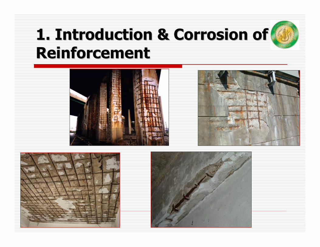
1. Introduction & Corrosion of 1. Introduction & Corrosion of ReinforcementReinforcement
Research ObjectiveResearch Objective
To study the flexural behavior of RC beam under different corrosion levels
To study the finite element modeling technique in predicting the flexural behavior of RC beam under corrosion
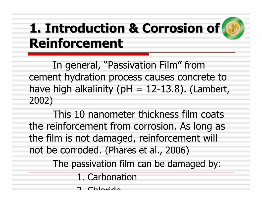
1. Introduction & Corrosion of 1. Introduction & Corrosion of ReinforcementReinforcement
In general, “Passivation Film” from cement hydration process causes concrete to have high alkalinity (pH = 12-13.8). (Lambert, 2002)
This 10 nanometer thickness film coats the reinforcement from corrosion. As long as the film is not damaged, reinforcement will not be corroded. (Phares et al., 2006)
The passivation film can be damaged by:1. Carbonation 2 Chloride
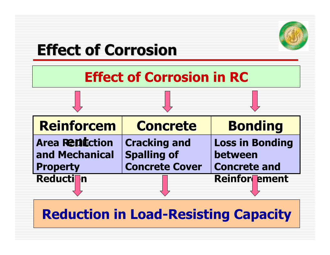
Effect of CorrosionEffect of Corrosion
Effect of Corrosion in RC
Loss in Bonding between Concrete and Reinforcement
Cracking and Spalling of Concrete Cover
Area Reduction and Mechanical Property Reduction
BondingBondingConcreteConcreteReinforcemReinforcementent
Reduction in Load-Resisting Capacity
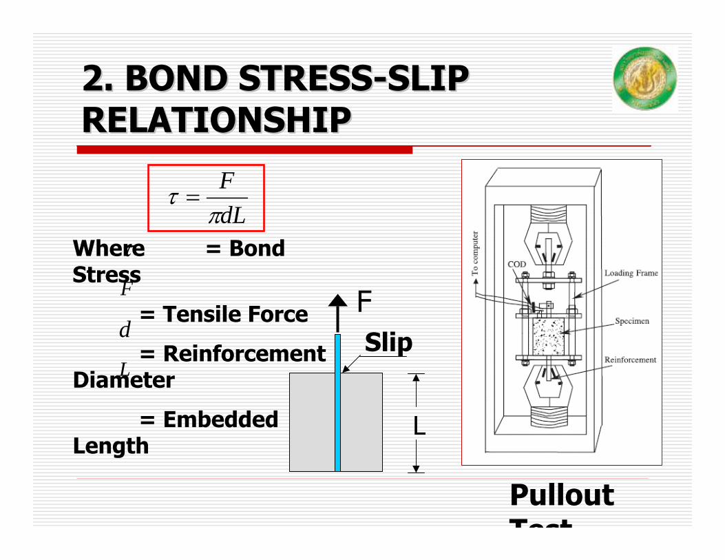
2. BOND STRESS2. BOND STRESS--SLIP SLIP RELATIONSHIPRELATIONSHIP
Pullout Test
dLFπ
τ =
Where = Bond Stress
= Tensile Force
= Reinforcement Diameter
= Embedded Length
τ
F
d
LSlip
L
F
Mathematical Model of Bond Mathematical Model of Bond Stress versus SlipStress versus Slip
Eligehausen(1983)
0
2
4
6
8
10
12
14
16
0 2 4 6 8 10 12 14 16
Slip (mm)
Bond
stress
(Mpa
)
Equation of Eligehausen. (1983)
Eligehausen. (1983)
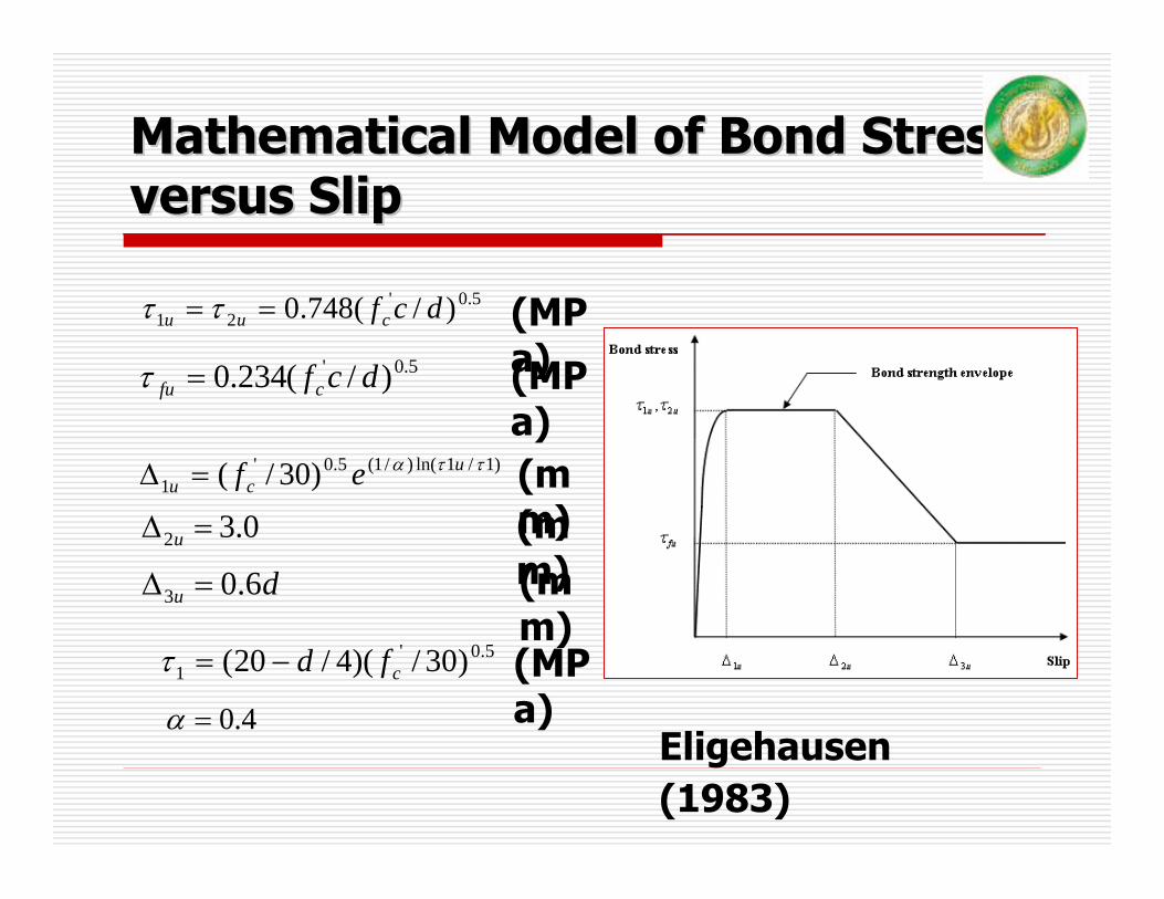
Mathematical Model of Bond Stress Mathematical Model of Bond Stress versus Slipversus Slip
5.0'21 )/(748.0 dcfcuu == ττ
5.0' )/(234.0 dcfcfu =τ
5.0'1 )30/)(4/20( cfd−=τ
)1/1ln()/1(5.0'1 )30/( ττα u
cu ef=∆
0.32 =∆ u
du 6.03 =∆
(MPa)(MPa)
(MPa)
(mm)(mm)(mm)
4.0=αEligehausen(1983)
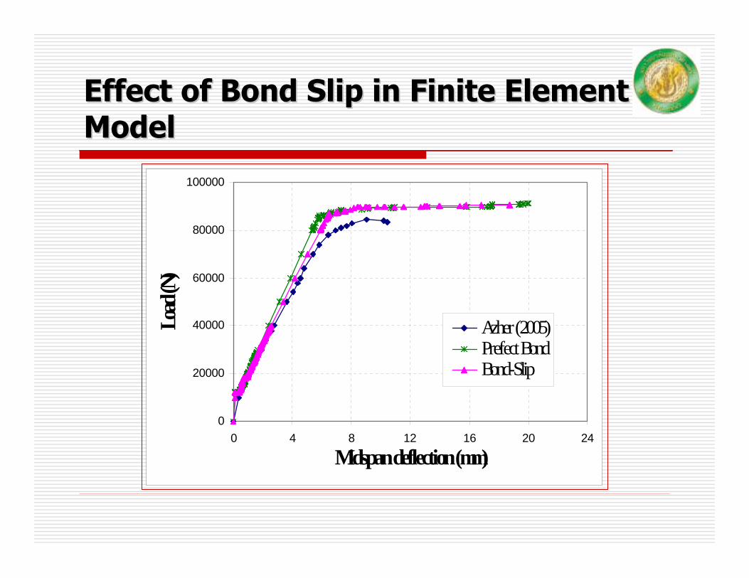
Effect of Bond Slip in Finite Element Effect of Bond Slip in Finite Element ModelModel
0
20000
40000
60000
80000
100000
0 4 8 12 16 20 24
Midspan deflection (mm)
Load
(N)
Azher (2005)Prefect BondBond-Slip

3. INFLUENCE OF CORROSION3. INFLUENCE OF CORROSION
Reduction in Reinforcement Area
)1( WAAc ∆−=
Where = Reinforcement Area after Corrosion
= Reinforcement Area before Corrosion
= Weight Loss Percentage of Reinforcement
cA
A
W∆
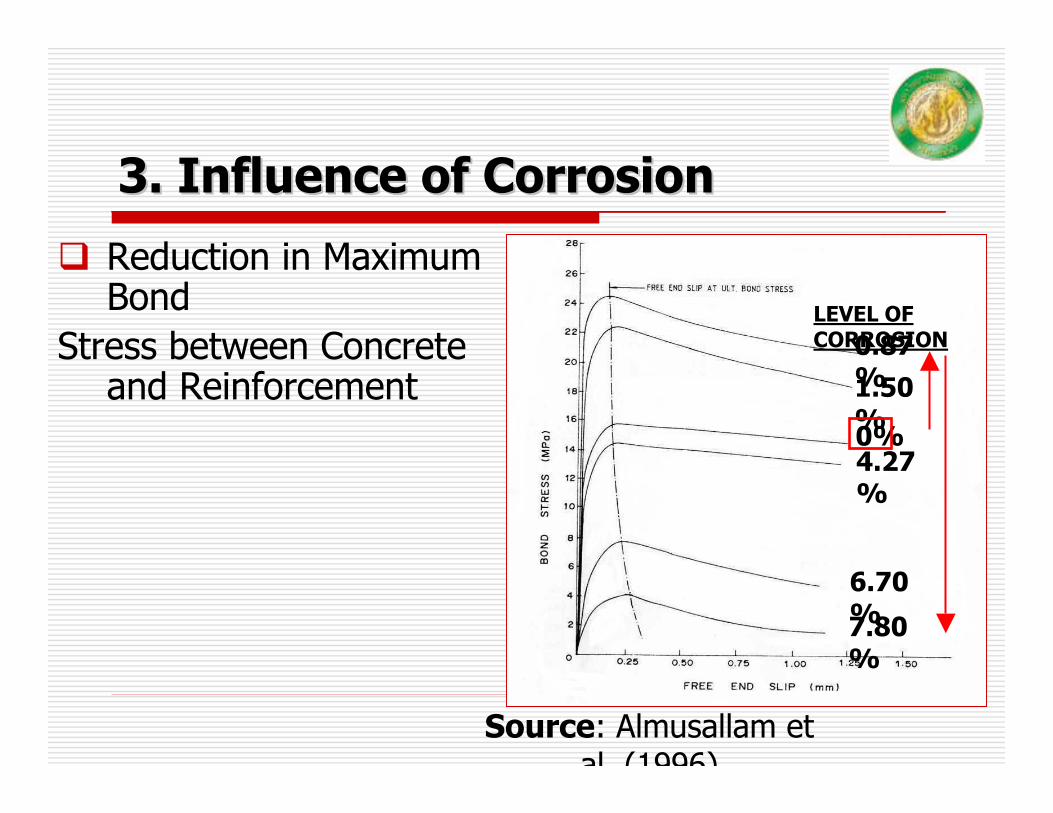
3. Influence of Corrosion3. Influence of Corrosion
Source: Almusallam et al (1996)
LEVEL OF CORROSION0.87
%1.50%0%4.27%
7.80%
6.70%
Reduction in Maximum Bond
Stress between Concrete and Reinforcement
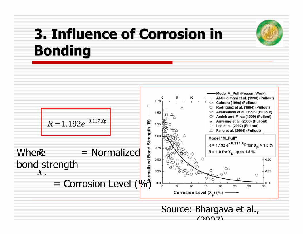
3. Influence of Corrosion in 3. Influence of Corrosion in BondingBonding
Source: Bhargava et al., (2007)
XpeR 117.0192.1 −=
Where = Normalized bond strength
= Corrosion Level (%)
R
PX
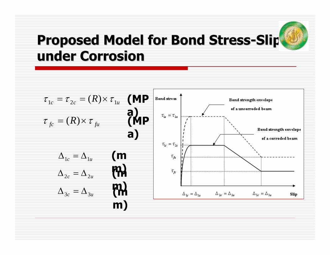
Proposed Model for Bond StressProposed Model for Bond Stress--Slip Slip under Corrosionunder Corrosion
ucc R 121 )( τττ ×==
fufc R ττ ×= )(
(MPa)(MPa)
uc 11 ∆=∆
uc 22 ∆=∆
uc 33 ∆=∆
(mm)(mm)(mm)
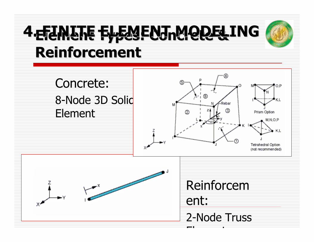
Element Types: Concrete & Element Types: Concrete & ReinforcementReinforcement
Concrete:8-Node 3D Solid Element
Reinforcement:2-Node Truss El t
4. FINITE ELEMENT MODELING4. FINITE ELEMENT MODELING

Element Types: BondElement Types: Bond--SlipSlip
2-Node Nonlinear Spring Element (Zero dimension)
Reinforcement Node
Concrete Node
4. Finite Element Modeling4. Finite Element Modeling
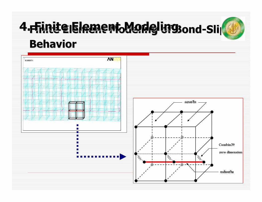
Finite Element Modeling of BondFinite Element Modeling of Bond--Slip Slip BehaviorBehavior
4. Finite Element Modeling4. Finite Element Modeling
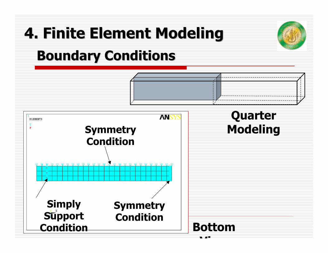
Boundary ConditionsBoundary Conditions
Symmetry Condition
Symmetry Condition
Simply Support
Condition Bottom Vi
4. Finite Element Modeling4. Finite Element Modeling
Quarter Modeling
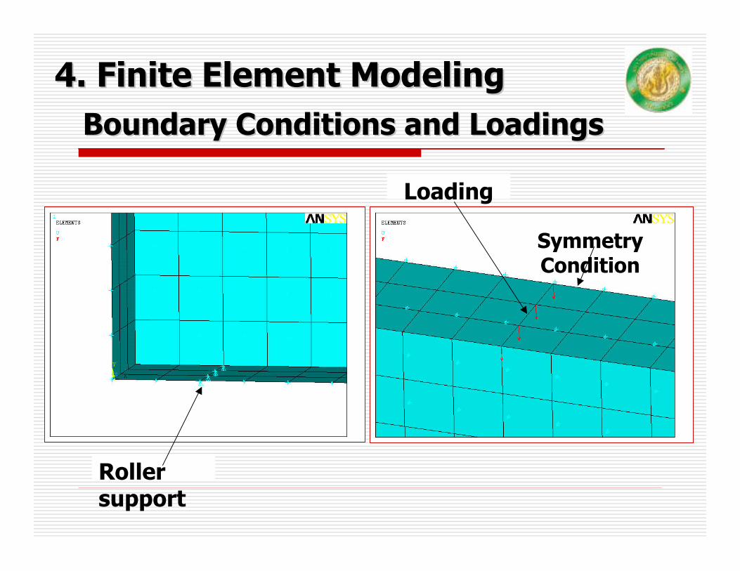
Boundary Conditions and LoadingsBoundary Conditions and Loadings
Roller support
Loading
Symmetry Condition
4. Finite Element Modeling4. Finite Element Modeling
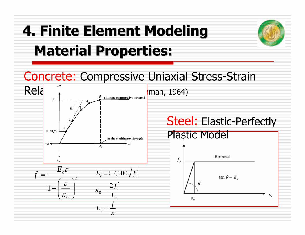
Material Properties:Material Properties:
Concrete: Compressive Uniaxial Stress-Strain Relationship (Desayi and Krishman, 1964)
c
c
Ef '
02
=ε
εfEc =
'000,57 cc fE =
Steel: Elastic-Perfectly Plastic Model
4. Finite Element Modeling4. Finite Element Modeling
2
0
1 ⎟⎟⎠
⎞⎜⎜⎝
⎛+
=
εε
εcEf
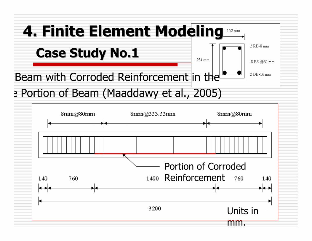
Case Study No.1Case Study No.1
Units in mm.
Portion of Corroded Reinforcement
Beam with Corroded Reinforcement in thee Portion of Beam (Maaddawy et al., 2005)
4. Finite Element Modeling4. Finite Element Modeling

Case Study No.1Case Study No.1
400Control beam
408.9CN-504014.2CN-1104022.2CN-210
Concrete Concrete Strength Strength
((MPaMPa))
CorrosioCorrosion Level n Level
(%)(%)BeamBeam
4 Levels of Corrosion
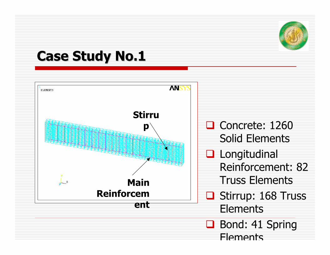
Case Study No.1Case Study No.1
Concrete: 1260 Solid Elements Longitudinal Reinforcement: 82 Truss ElementsStirrup: 168 Truss ElementsBond: 41 Spring Elements
Stirrup
Main Reinforcem
ent
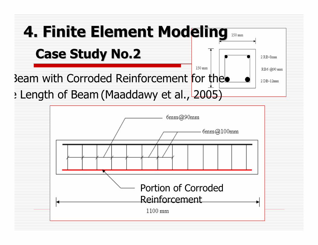
Case Study No.2Case Study No.2
Portion of Corroded Reinforcement
Beam with Corroded Reinforcement for the e Length of Beam (Maaddawy et al., 2005)
4. Finite Element Modeling4. Finite Element Modeling
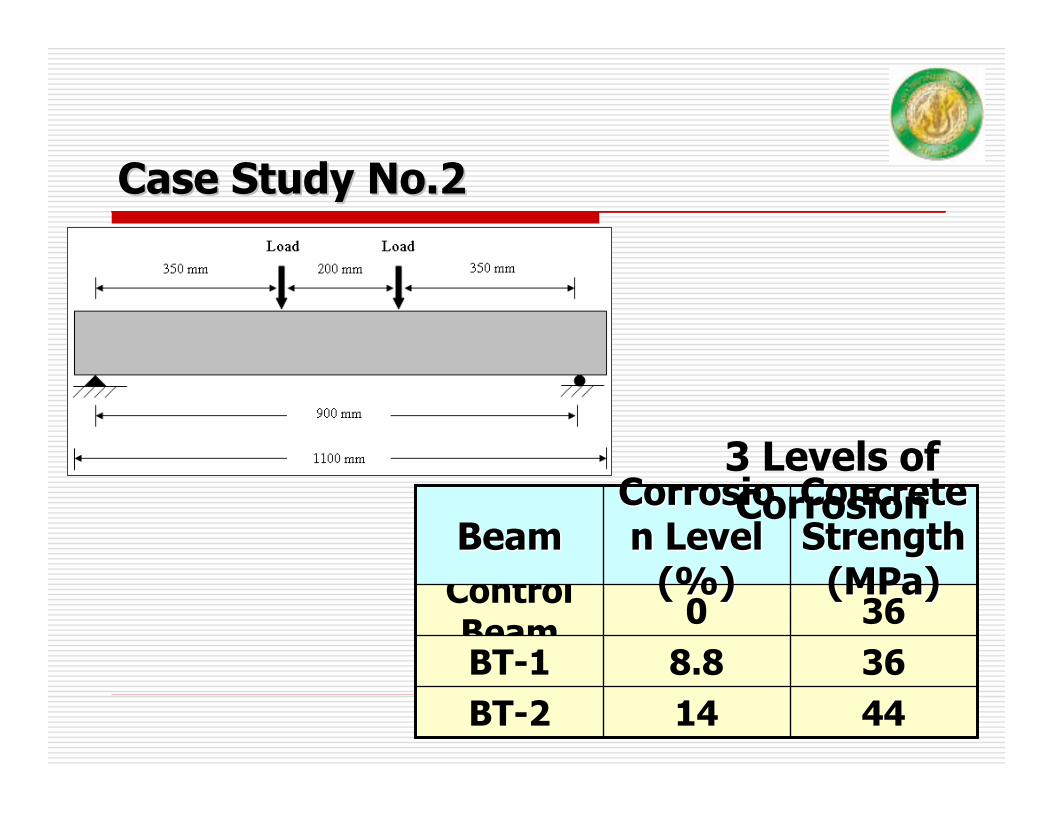
Case Study No.2Case Study No.2
360Control Beam
368.8BT-14414BT-2
Concrete Concrete Strength Strength
((MPaMPa))
CorrosioCorrosion Level n Level
(%)(%)BeamBeam
3 Levels of Corrosion

Case Study No.2Case Study No.2
Concrete: 468 Solid Elements Longitudinal Reinforcement: 48 Truss ElementsStirrup: 48 Truss ElementsBond: 24 Spring Elements
Stirrup
Main Reinforcem
ent
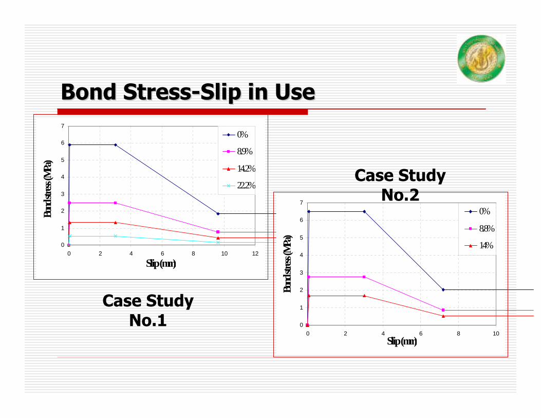
Bond StressBond Stress--Slip in UseSlip in Use
0
1
2
3
4
5
6
7
0 2 4 6 8 10 12
Slip (mm)
Bond
stress
(MPa
)
0%
8.9%
14.2%
22.2%
0
1
2
3
4
5
6
7
0 2 4 6 8 10Slip (mm)
Bond
stress
(MPa
)
0%
8.8%
14%
Case Study No.1
Case Study No.2
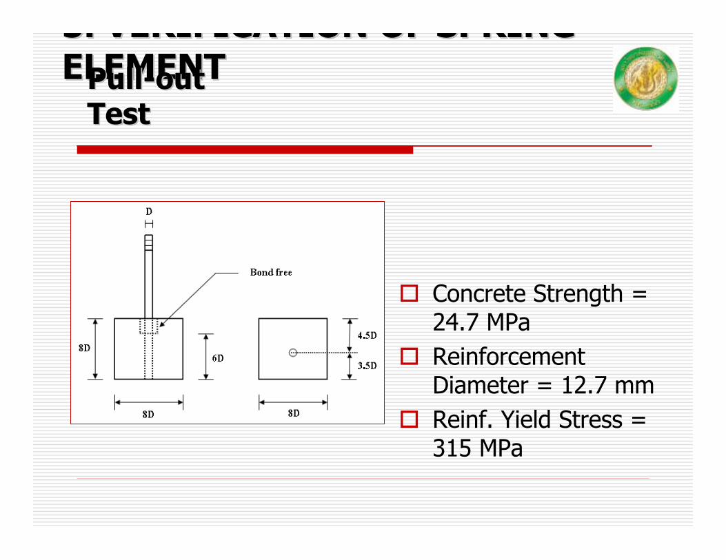
5. VERIFICATION OF SPRING 5. VERIFICATION OF SPRING ELEMENTELEMENT
Concrete Strength = 24.7 MPaReinforcement Diameter = 12.7 mmReinf. Yield Stress = 315 MPa
PullPull--out out TestTest
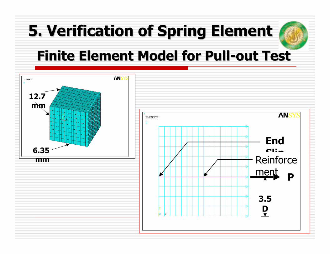
Finite Element Model for PullFinite Element Model for Pull--out Testout Test
P
End Slip
3.5D
6.35 mm
12.7 mm
Reinforcement
5. Verification of Spring Element5. Verification of Spring Element

Relationship between Bond StressRelationship between Bond Stress--Slip and Input ForceSlip and Input Force--Displacement for Displacement for Spring ElementSpring Element
TestTestF
L
dLFπ
τ = ModModelel
dLF τπ=
L
Concrete
Reinforcement
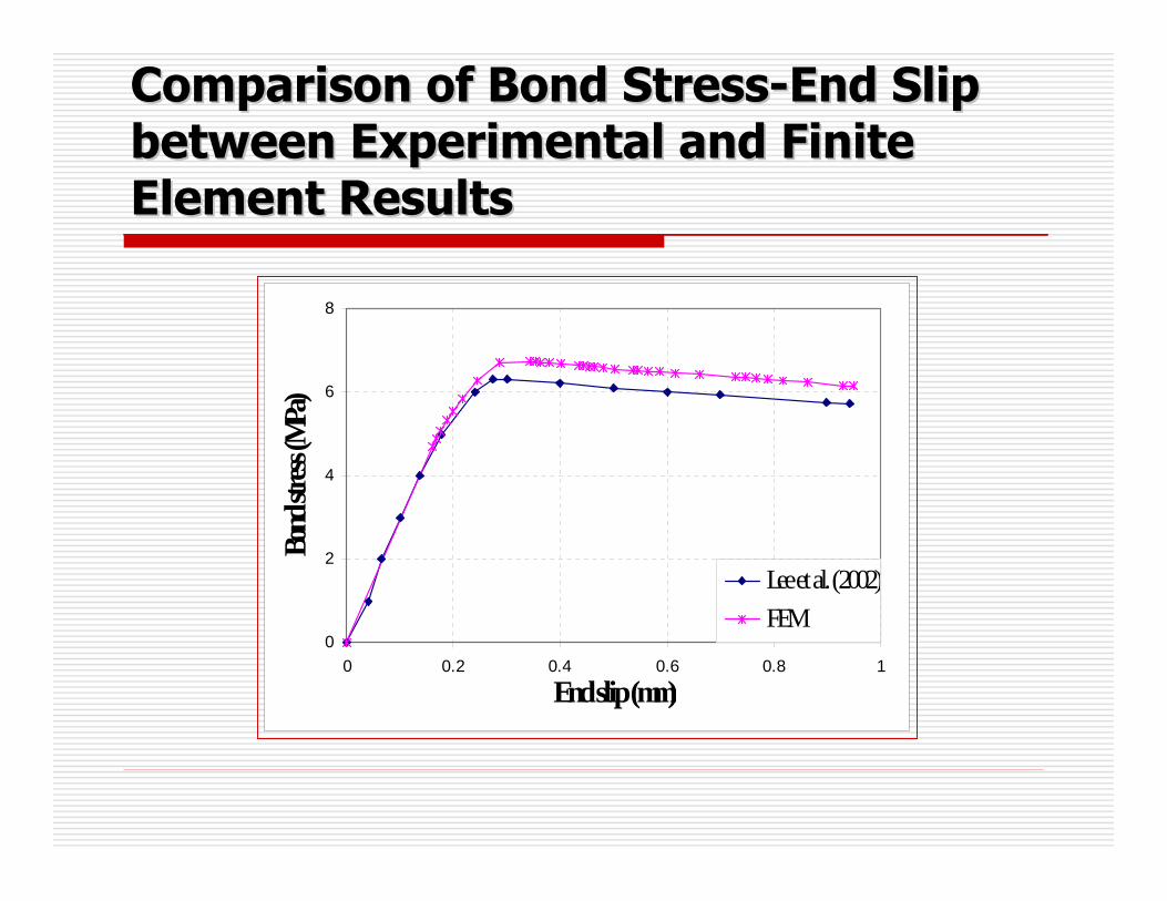
Comparison of Bond StressComparison of Bond Stress--End Slip End Slip between Experimental and Finite between Experimental and Finite Element ResultsElement Results
0
2
4
6
8
0 0.2 0.4 0.6 0.8 1
End slip (mm)
Bond
stress
(MPa
)
Lee et al. (2002)FEM

6. FINITE ELEMENT RESULTS6. FINITE ELEMENT RESULTS
6.1 Case Study No.16.1 Case Study No.1RC Beam with Corroded RC Beam with Corroded
Reinforcement in the Middle Reinforcement in the Middle Portion of BeamPortion of Beam
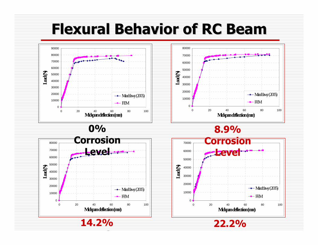
Flexural Behavior of RC BeamFlexural Behavior of RC Beam
0
10000
20000
30000
40000
50000
60000
70000
80000
90000
0 20 40 60 80 100Midspan deflection (mm)
Load
(N)
Maaddawy (2005)FEM
0
10000
20000
30000
40000
50000
60000
70000
80000
0 20 40 60 80 100
Midspan deflection (mm)
Load
(N)
Maaddawy (2005)FEM
0
10000
20000
30000
40000
50000
60000
70000
80000
0 20 40 60 80 100
Midspan deflection (mm)
Load
(N)
Maaddawy (2005)FEM
0
10000
20000
30000
40000
50000
60000
70000
0 20 40 60 80 100
Midspan deflection (mm)
Load
(N)
Maaddawy (2005)
FEM
0% Corrosion
Level
8.9% Corrosion
Level
14.2% i
22.2%

Stress Distribution in Beam St ess st but o eaSectionSection
0
127
254
-45 -35 -25 -15 -5 5Stress (MPa)
Secti
on (m
m)1000013442134432000030000400005000060000700007500079035
0
127
254
-45 -35 -25 -15 -5 5
Stress (MPa)
Secti
on (m
m)
10000131651316620000300004000050000600007000071633
0
127
254
-45 -35 -25 -15 -5 5Stress (MPa)
Secti
on (m
m)
10000130201302120000300004000050000600006500068018
0
127
254
-45 -35 -25 -15 -5 5Stress (MPa)
Secti
on (m
m)
10000
12757
12758
20000
30000
40000
50000
60000
61125
0% Corrosion
Level
8.9% Corrosion
Level
14.2% i
22.2%
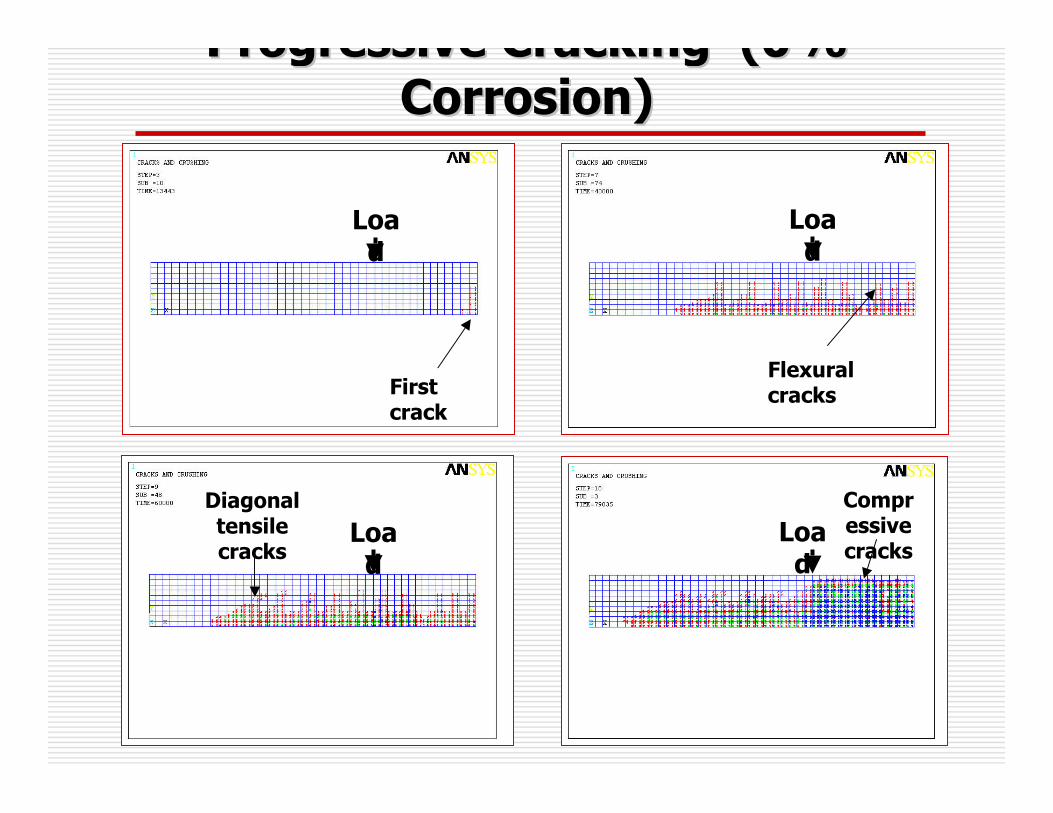
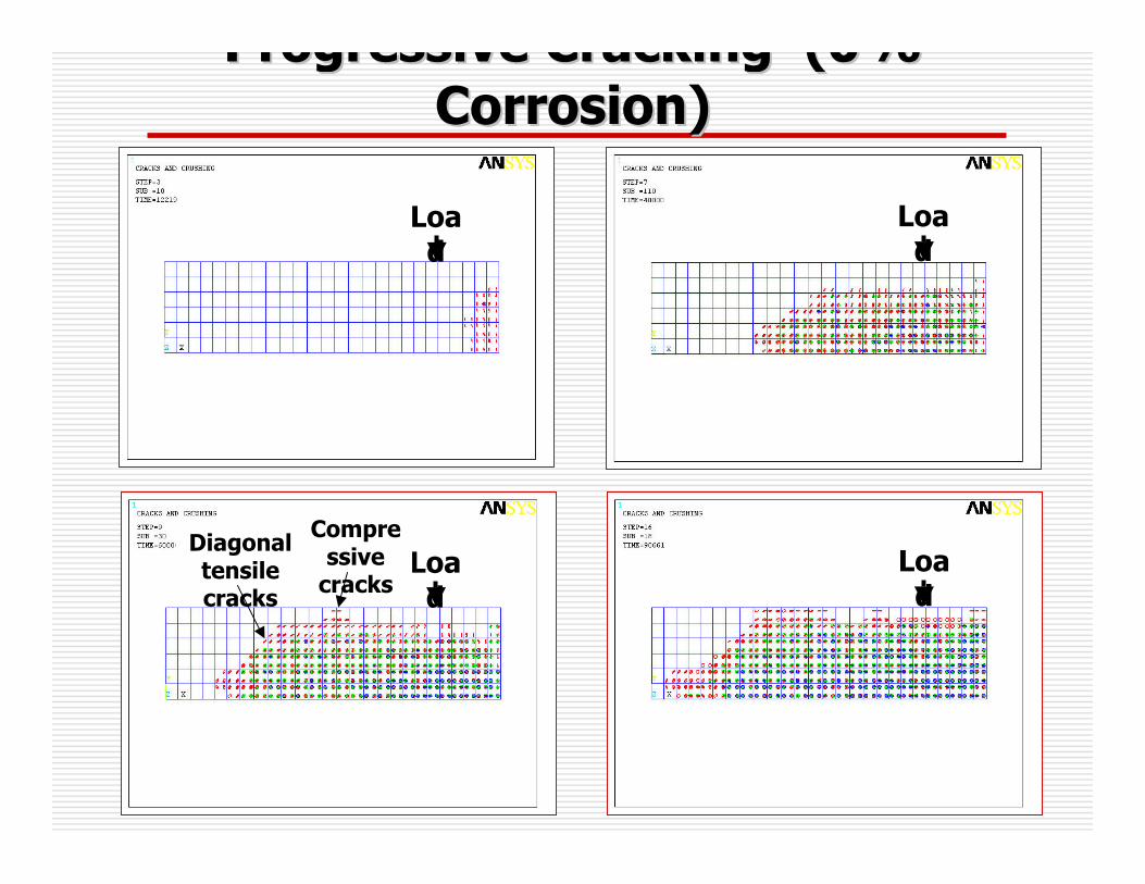
Progressive Cracking (0% Progressive Cracking (0% Corrosion)Corrosion)
First crack
Load
Load
Load
Diagonal tensile cracks
Compressive cracks
Load
Flexural cracks

Progressive Cracking (8.9% Progressive Cracking (8.9% Corrosion)Corrosion)
Load
Diagonal tensile cracks
Compressive
cracks
First crack
Load
Flexural cracks
Load
First crack
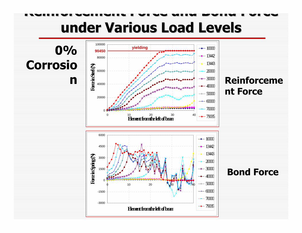
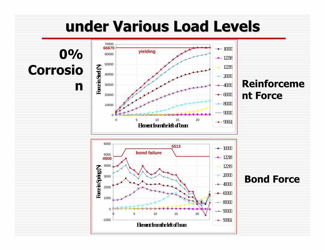
Reinforcement Force and Bond Force Reinforcement Force and Bond Force under Various Load Levelsunder Various Load Levels
-3000
-1500
0
1500
3000
4500
6000
0 10 20 30 40
Element from the left of beam
Force
in Sp
ring (
N)
10000134421344320000300004000050000600007000079035
0
20000
40000
60000
80000
100000
0 10 20 30 40Element from the left of beam
Force
in St
eel (N
)
10000134421344320000300004000050000600007000079035
0% Corrosio
n
Bond Force
90450yielding
Reinforcement Force

Reinforcement Force and Bond Force Reinforcement Force and Bond Force under Various Load Levelsunder Various Load Levels
8.9% Corrosion
-3000
-1500
0
1500
3000
4500
6000
0 10 20 30 40
Element from the left of beam
Force
in Sp
ring (
N)
10000131651316620000300004000050000600007000071633
0
20000
40000
60000
80000
100000
0 10 20 30 40Element from the left of beam
Force
in St
eel (N
)
10000131651316620000300004000050000600007000071633
yielding82350
Bond Force
Reinforcement Force
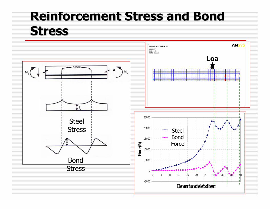
Reinforcement Stress and Bond Reinforcement Stress and Bond StressStress
-5000
0
5000
10000
15000
20000
25000
0 4 8 12 16 20 24 28 32 36 40
Element from the left of beam
Forc
e (N)
แรงในเหล็กเสริม
แรงยึดเหนี่ยว
Load
Bond Stress
Steel Stress Steel
ForceBond Force

Moment CapacityMoment Capacity
61,125
68,018
71,663
79,035
Ultimate Ultimate loadload
FEM (N)FEM (N)
30,562
34,009
35,816
39,517
Max. Max. MomentMoment
((kNkN--mm)mm)
22.7522.2
13.9414.2
9.378.9
-0
Reduce Reduce MomentMoment
(%)(%)
CorrosioCorrosion n
(%)(%)

6. Finite Element Analysis 6. Finite Element Analysis ResultsResults
6.2 Case Study No.26.2 Case Study No.2RC Beam with Corroded RC Beam with Corroded
Reinforcement for the Whole Reinforcement for the Whole Length of BeamLength of Beam

Flexural Behavior of RC BeamFlexural Behavior of RC Beam
0
10000
20000
30000
40000
50000
60000
70000
80000
90000
100000
0 5 10 15 20 25Midspan deflection (mm)
Load
(N)
Azher (2005)FEM
0
10000
20000
30000
40000
50000
60000
70000
80000
0 5 10 15 20 25
Midspan deflection (mm)
Load
(N)
Azher (2005)FEM
0
10000
20000
30000
40000
50000
60000
70000
0 5 10 15 20
Midspan deflection (mm)
Load
(N)
Azher (2005)
FEM
0% Corrosion
Level
8.8% 14%
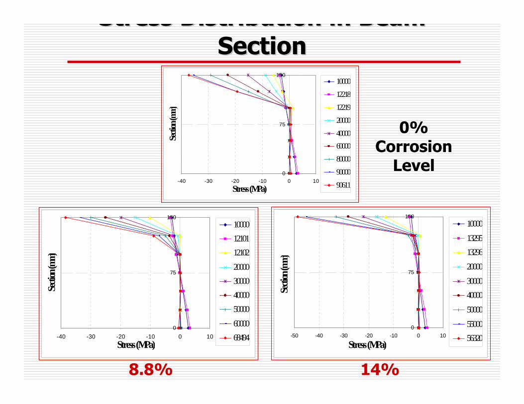
Stress Distribution in Beam Stress Distribution in Beam SectionSection
0
75
150
-40 -30 -20 -10 0 10
Stress (MPa)
Secti
on (m
m)
100001221812219200004000060000800009000090611
0
75
150
-40 -30 -20 -10 0 10Stress (MPa)
Secti
on (m
m)
100001210112102200003000040000500006000068494
0
75
150
-50 -40 -30 -20 -10 0 10
Stress (MPa)
Secti
on (m
m)
100001329513296200003000040000500005500056320
0% Corrosion
Level
8.8% 14%
Load
Load
Load
Load
Compressive
cracks
Diagonal tensile cracks
Progressive Cracking (0% Progressive Cracking (0% Corrosion)Corrosion)

Load
Load
Load
Diagonal tensile cracks
Compressive
cracks
First crack
Load
og ess e C ac g (8 8%g g (Corrosion)Corrosion)
0
10000
20000
30000
40000
50000
60000
70000
0 5 10 15 20
Element from the left of beam
Force
in St
eel (N
)
10000
12218
12219
20000
40000
60000
80000
90000
90661
yielding66670
-1000
0
1000
2000
3000
4000
5000
6000
0 5 10 15 20
Element from the left of beam
Force
in Sp
ring (
N)
10000
12218
12219
20000
40000
60000
80000
90000
90661
bond failure4900
5513
under Various Load Levelsunder Various Load Levels
0% Corrosio
n
Bond Force
Reinforcement Force
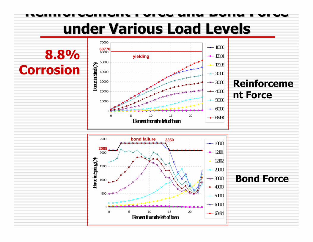
0
500
1000
1500
2000
2500
0 5 10 15 20
Element from the left of beam
Force
in Sp
ring (
N)
10000
12101
12102
20000
30000
40000
50000
60000
68494
0
10000
20000
30000
40000
50000
60000
70000
0 5 10 15 20
Element from the left of beam
Force
in St
eel (N
)
10000
12101
12102
20000
30000
40000
50000
60000
68494
yielding60770
bond failure
2088
2350
Reinforcement Force and Bond Force Reinforcement Force and Bond Force under Various Load Levelsunder Various Load Levels
8.8% Corrosion
Bond Force
Reinforcement Force

0
450
900
1350
1800
0 5 10 15 20
Element from the left of beam
Force
in Sp
ring (
N)
10000
13295
13296
20000
30000
40000
50000
56320
0
10000
20000
30000
40000
50000
60000
70000
0 5 10 15 20
Element from the left of beam
Force
in ste
el (N)
10000
13295
13296
20000
30000
40000
50000
56320
yielding57230
bond failure
1495
1683
Reinforcement Force and Bond Force Reinforcement Force and Bond Force under Various Load Levelsunder Various Load Levels
14% Corrosion
Bond Force
Reinforcement Force

Moment CapacityMoment Capacity
56,320
68,494
90,661
Ultimate Ultimate loadload
FEM (N)FEM (N)
9,856
11,986
15,865
Max. Max. MomentMoment
((kNkN--mm)mm)
37.8814
24.458.8
-0
Reduce Reduce MomentMoment
(%)(%)
ระดับสนิมระดับสนิม(%)(%)
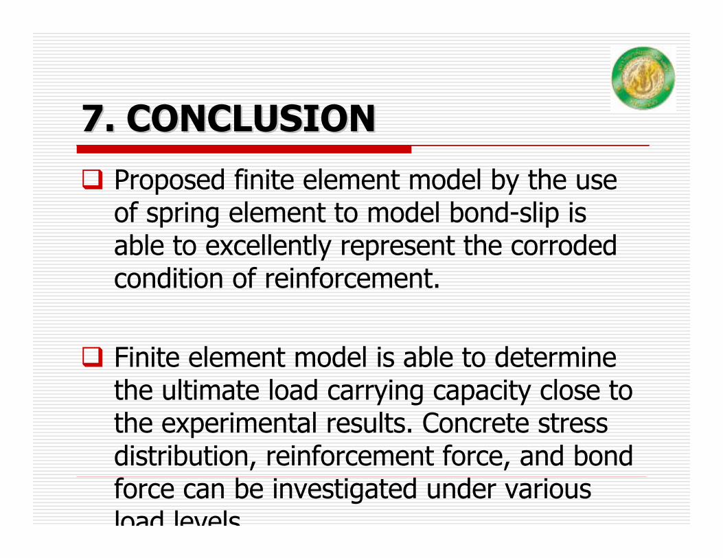
7. CONCLUSION7. CONCLUSIONProposed finite element model by the use of spring element to model bond-slip is able to excellently represent the corroded condition of reinforcement.
Finite element model is able to determine the ultimate load carrying capacity close to the experimental results. Concrete stress distribution, reinforcement force, and bond force can be investigated under various load levels

7. Conclusion 7. Conclusion (cont(cont’’d)d)
Corrosion of reinforcement in the middle portion of RC beam results in yielding failure of reinforcement at the ultimate load capacity.Corrosion of reinforcement for the whole length of RC beam results in bond failure at the ultimate load and greatly reduce the moment resisting capacity.
Corrosion in middle portion
Corrosion for the whole length

Questions ?