photography for engineering documentation … requirements/photography for...photography for...
TRANSCRIPT
Page 1 of 9 © 2011-2013 Department of Civil Engineering - Southern Illinois University Edwardsville Rev. 2/7/2013
Photography for Engineering Documentation
Introduction
Photographs are a very important engineering tool commonly used to document explorations, observations, laboratory and field test results and as-built conditions. Photographs not only help you tell the story to others but can also help remind you about important features of a project. Reexamining a photograph can even help you see something you may not have noticed when you were originally on the site or viewing test results for the first time.
Photographs can also be critically important in determining why something failed or changed in some way, which is the objective of forensic engineering. Forensic engineering is a special type of engineering that often deals with legal proceedings that involve determining why something has failed or not performed to some level of satisfaction. Forensic explorations then become highly detailed and forensic photographs are key testimony materials. At this level of photography, specific information regarding the geometry of the positions and technical parameters of the entire photographic system involved in making the image are used to aid in computing dimensions, shades, colors, textures and lighting conditions must also be part of the data record. Two broad categories of forensic photography are documentary and metric. Documentary photographs are analogous to sketches or simple notes as there is not usually the intent to accurately convey scale or proportion information. On the other hand, metric photographs are more carefully produced like an engineering drawing with close attention to the geometry and spatial relationships of the subject and photography equipment. Even accurate rendering of color and shades and type of lighting may be called for in certain cases. With this higher degree of control over creating the image, specific or otherwise significant, quantitative characteristics of the subject can be discerned from the photograph.
The photographs that you take of test specimens in laboratory courses will be part of the data used to illustrate the observations for your experiment. These pictures will serve to show how a specimen deformed or ruptured, providing you and other viewers with detailed evidence that can be difficult to adequately describe using words and numbers alone. For the purposes of most engineering documentation you will not need to achieve the high level of detail required for a forensic investigation. However, you still want to take care to record images that accurately depict the subject either by itself or in its surroundings.
General photography suggestions
Here are some things to consider to achieve good quality photographic documentation for engineering reports.
1. Take lots of photographs. You can choose which ones to keep and use later.
2. Respect privacy. Be very careful when taking photographs that include people, whether in private or public settings, or of private property. The law and the perception each potential subject person has regarding the right to privacy by not being photographed is complicated. If you can take photographs of the subject and it does not require people to be in it to make your point, then wait until no one will be in the photograph. You should never trespass to take a photograph. You should look up some sources of information on photography law and the rights of photographers.
3. Establish the general location. Take photographs standing back at a distance to establish the project surroundings. These photographs help to establish a sense of scale and how the project fits into its surroundings. Shoot from a high (aerial) point of
Page 2 of 9 © 2011-2013 Department of Civil Engineering - Southern Illinois University Edwardsville Rev. 2/7/2013
view if feasible and from the point of view of an observer on the ground. Sometimes the photographer’s location is depicted on a map to help the viewer get a better feel for where the subject project is.
4. Depict the subject in its setting. If possible and safe, come closer to the subject of the photograph, such as to frame the entire bridge or culvert. This helps the viewer to narrow the frame of reference and concentrate on the main subject. This is where many details may be highlighted if clearly visible at this scale.
5. Focus on details. Zoom in or use macro-focus to take a close-up view of some detail. In most cases you can focus as close as 8 to 12 inches from a subject which may provide enough detail for your purposes. In other cases, you may need to focus much closer in order to see small details that are important. Many cameras, including most point-and-shoot digital cameras, have a macro-focus mode (usually indicated with a flower symbol) that will allow you to position the front of the camera lens to within a few inches of the subject. When you get close to the subject you should consider turning the flash to OFF to avoid hot-spots and unequal coverage of the flash. Also be sure to avoid moving the camera because at close distance and low light any camera movement becomes very apparent by blurring the picture.
6. Convey a sense of scale. Depending on the purpose of the photograph, you should try to include some size reference in the picture. When possible, include an object such as a scale (ruler) or common object (a coin, pencil, even a finger or foot) to help convey a sense of scale.
7. Make it measurable. Minimize the effect of perspective by keeping all critical points of the object at the same distance from the camera imaging plane, which is usually parallel to the back of the camera.
8. Write down the key observations about the subject. Record notes for each photograph. Jot down the things about the photograph that you most want to remember or have the viewer observe in picture, especially if it is something that might be hard to visualize such as changes over time, non-visual properties (sounds, odors, etc.), and boundaries.
9. Use adequate lighting. For daylight photographs taken outdoors this will normally not be a problem. For other times of the day (night), and for most indoor scenes, you may need to provide artificial lighting, such as from the camera’s built-in or accessory flash device. Since the light intensity from a flash diminishes as the inverse of the square of the distance from the camera, a scene covering a large space will be unevenly lit causing near surfaces to be too bright and far surfaces to be too dim. Your artificially lighted object must usually be within a few feet from the camera. You may be able to use available light to capture a more evenly lit scene but the long exposure time will require you to steady the camera with a tripod or resting against a stationery object to reduce blur from camera-shake motion.
10. When in doubt, take a picture. Take lots of photographs, but avoid violating people’s right to privacy.
11. Be aware of a picture's background. Many pictures have been taken with a tree growing out of a person's head or distracting objects that in the background.
12. Use a neutral, non-patterned backdrop (towel, sheet, poster board, etc.) This will keep these pictures’ background free of clutter. If a backdrop is not available then set the camera for a large aperture to cause the background to appear blurry (see below). Note: an f-stop is the ratio of the lens' focal length to its diameter; an f-stop of 2.5 (f2.5) would correspond to a large aperture, f32 would represent a small aperture.
Page 3 of 9 © 2011-2013 Department of Civil Engineering - Southern Illinois University Edwardsville Rev. 2/7/2013
13. Large apertures result in a photograph with a shallow depth of field (the portion of the picture that is in sharp focus) so you have to carefully focus on the most important feature to make sure it is sharp in the photograph. This reduces the distraction of a busy background. The aperture can be controlled by setting the camera to manual mode. Other ways to reduce the depth of field: reduce the distance between the camera and the subject; increase the distance between the subject and the background; if you have a zoom lens then set it in the telephoto range; use the Portrait mode which will set the camera for a large aperture (a small f-stop).
14. Using a flash often results in harsh shadows. Taking a picture in low light without a flash will require a large aperture to admit more light, a long exposure (less than 1/32 second) or both. It might be possible to cast more light on a subject by using a reflective surface such as a white poster board or lightly crumpled sheet of aluminum foil. Blurry pictures are common with long exposure times although this can be minimized by using a tripod. Even on a tripod, pressing the shutter release often introduces camera movement but this can be minimized by using the self-timer to trip the shutter. If a tripod is not available then hold the camera steady by doing the following: press your elbows against your sides; lean against a stationary object; take a deep breath, let half of it out and hold the remaining breath while activating the self-timer.
15. Use a lens’ “sweet spot” when possible. A lens’ sweet spot is a specific aperture setting where the lens will produce its sharpest possible results, it is usually located two or three stops above the lens’ maximum aperture. In an f/2.8 lens the sweet spot would be at f5.6 or f8.
The following pages include examples of combining photographs with annotations to include in reports and other correspondence, or just for your benefit and the project file.
Page 4 of 9 © 2011-2013 Department of Civil Engineering - Southern Illinois University Edwardsville Rev. 2/7/2013
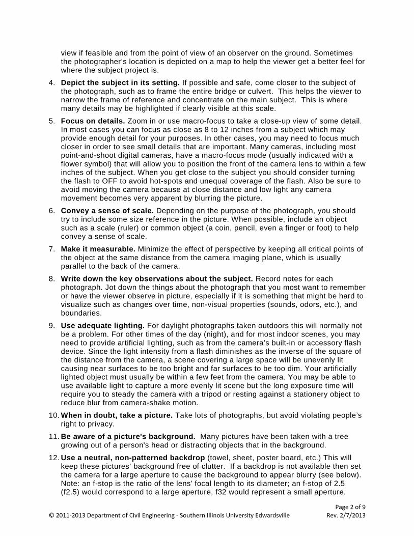
Figure 2 - Detail of strain gage bonded to the cantilevered beam. The gage is the grid pattern on the left, and the thin leads provide a low-stress connection to the terminal pad on the right where the relatively heavy wires going to the instrumentation are connected. (Note: This photograph was taken using a 60mm macro lens mounted on a digital SLR camera. Since even most small point-and-shoot digital cameras have some kind of macro-focus setting for close-up focusing (typically indicated by a flower symbol), you should learn to use that mode for close-ups. A small plastic scale was added as a size reference. The scale is marked in cm.)
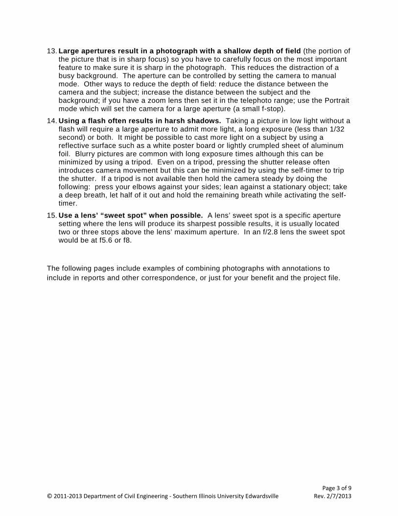
Figure 3 – View of the oscilloscope display showing the signal output from the signal conditioner immediately after the beam was flicked. The vertical scale is 100 mV/division and the horizontal scale is 10 ms/division. (Note: The bright spot in the upper left hand area of the picture is from the room lights.)
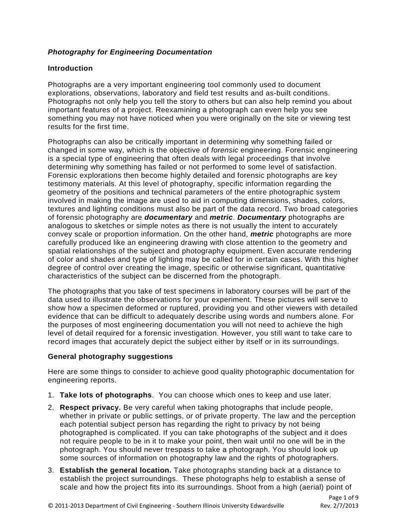
Exhibit 1 – A lab experiment setup with equipment details and displays.
We use a strain gage bonded to a cantilevered aluminum bar to experiment with and learn about strain-gage-based instrumentation. The figures below show the general layout of the experiment equipment, a close-up view of the strain gage bonded to the beam, and a photograph of the oscilloscope display capturing the vibration sensed by the strain gage as the beam is flicked to setup vibrations and the natural frequency of the beam.
Figure 1 - General equipment layout for the Strain Gage lab experiment. The equipment shown is (from top to bottom): power supply, strain gage signal conditioner/amplifier, cantilevered beam device with strain gage.
Page 5 of 9 © 2011-2013 Department of Civil Engineering - Southern Illinois University Edwardsville Rev. 2/7/2013
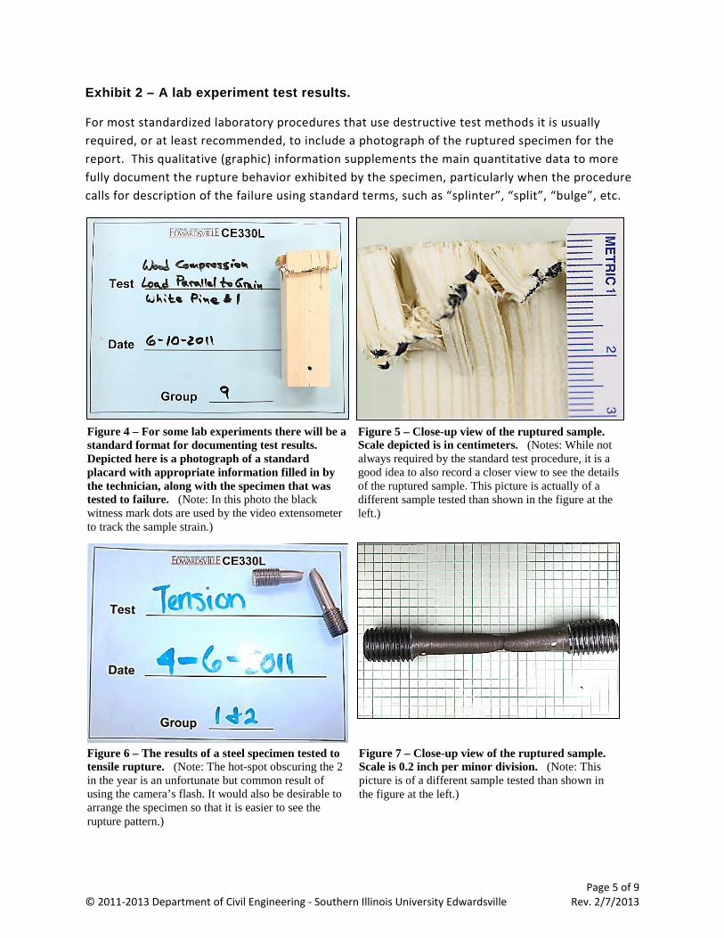
Exhibit 2 – A lab experiment test results.
For most standardized laboratory procedures that use destructive test methods it is usually required, or at least recommended, to include a photograph of the ruptured specimen for the report. This qualitative (graphic) information supplements the main quantitative data to more fully document the rupture behavior exhibited by the specimen, particularly when the procedure calls for description of the failure using standard terms, such as “splinter”, “split”, “bulge”, etc.
Figure 4 – For some lab experiments there will be a standard format for documenting test results. Depicted here is a photograph of a standard placard with appropriate information filled in by the technician, along with the specimen that was tested to failure. (Note: In this photo the black witness mark dots are used by the video extensometer to track the sample strain.)
Figure 5 – Close-up view of the ruptured sample. Scale depicted is in centimeters. (Notes: While not always required by the standard test procedure, it is a good idea to also record a closer view to see the details of the ruptured sample. This picture is actually of a different sample tested than shown in the figure at the left.)
Figure 6 – The results of a steel specimen tested to tensile rupture. (Note: The hot-spot obscuring the 2 in the year is an unfortunate but common result of using the camera’s flash. It would also be desirable to arrange the specimen so that it is easier to see the rupture pattern.)
Figure 7 – Close-up view of the ruptured sample. Scale is 0.2 inch per minor division. (Note: This picture is of a different sample tested than shown in the figure at the left.)
Page 8 of 9 © 2011-2013 Department of Civil Engineering - Southern Illinois University Edwardsville Rev. 2/7/2013
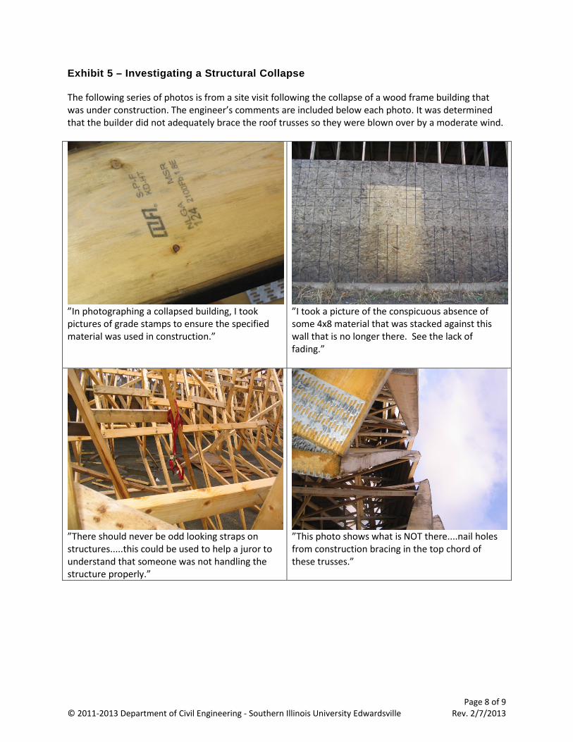
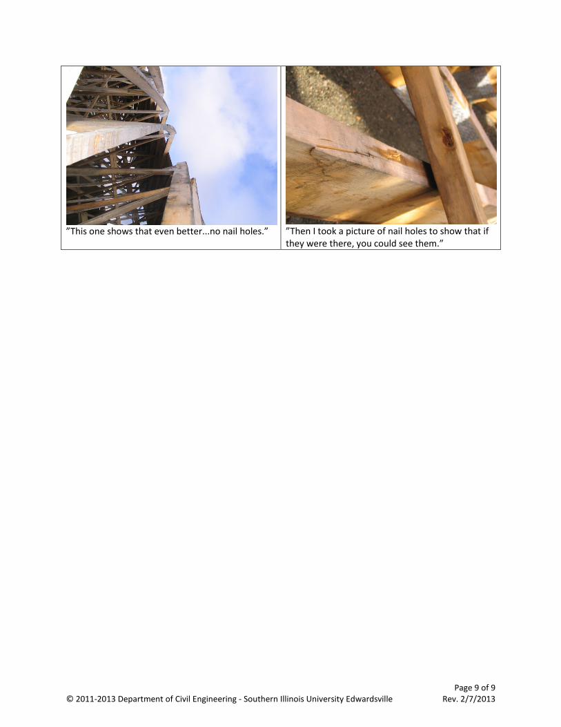
Exhibit 5 – Investigating a Structural Collapse The following series of photos is from a site visit following the collapse of a wood frame building that was under construction. The engineer’s comments are included below each photo. It was determined that the builder did not adequately brace the roof trusses so they were blown over by a moderate wind.
”In photographing a collapsed building, I took pictures of grade stamps to ensure the specified material was used in construction.”
”I took a picture of the conspicuous absence of some 4x8 material that was stacked against this wall that is no longer there. See the lack of fading.”
”There should never be odd looking straps on structures.....this could be used to help a juror to understand that someone was not handling the structure properly.”
”This photo shows what is NOT there....nail holes from construction bracing in the top chord of these trusses.”
Page 9 of 9 © 2011-2013 Department of Civil Engineering - Southern Illinois University Edwardsville Rev. 2/7/2013
”This one shows that even better...no nail holes.” ”Then I took a picture of nail holes to show that if they were there, you could see them.”