photodiode test using the keysight b2980a series ... · pdf filephotodiode test using the...
TRANSCRIPT

Keysight Technologies Photodiode Test Using the Keysight B2980A SeriesB2981A/83A Femto/PicoammeterB2985A/87A Electrometer/High Resistance Meter
Technical Overview

Introduction
A photodiode (PD) is a semiconductor device that converts light into current. When the PD is reverse-biased, a current is generated as the PD absorbs photons. The PD also produces a small amount of current when no light is present; this is known as dark current. Since the output current is directly proportional to the light intensity applied to the PD junction, it can be used to detect small quantities of light. This makes PDs useful in a wide range of applications such as optical communica-tion, light detection, and consumer electronics.
When the PD is reverse-biased, the output current consists of dark current (no light) and photocurrent (caused by light). Dark current is a small leakage current induced by applied voltage. Photocurrent is typically constant as a function of applied voltage. The dark current is caused by thermal leakage in the PN junction, so it is frequently characterized as a function of temperature. The photocurrent and dark current measurements should be made with an instrument that can sweep voltage and measure current over a wide range (such as an electrometer or source measure unit).
Avalanche photodiodes (APDs) are high-speed photodiodes with high sensitivity, and they exhibit internal current gain when a large reverse bias is applied. By varying the magnitude of the reverse bias voltage, the gain of the APD can be controlled. In general, a larger reverse bias voltage results in higher gain. However, APDs can require high voltages (many hundreds of volts) to fully characterize them.
APDs are used in a variety of applications requiring high sensitivity to light (such as fiber optic tele-communication and laser rangefinders). Common APD electrical parameters include responsivity, breakdown voltage, and reverse bias current. The current rating for a typical APD under reverse bias is 100 µA to 10 mA, while the dark current can be as low as 1 pA or less. The maximum reverse bias voltage varies with the material from which the APD is fabricated, and for Si devices it can be as high as 500 V.
The Keysight Technologies, Inc. B2980A Series Femto/Picoammeters and Electrometer/High Resis-tance Meters are the world’s only graphical picoammeters and electrometers that can confidently measure down to 0.01 fA and up to 10 PΩ (1016 Ω). These capabilities give them the ability to evaluate a variety of PDs. The B2980A Series’ ammeter provides 0.01 fA current resolution and multiple current measurement ranges (from 2 pA to 20 mA), which can meet all existing and future PD low-current measurement needs. The voltage source of the B2980A Series’ electrometers has 1,000 V voltage sourcing capability that can support PD evaluation requiring high voltage (such as APDs). Unlike conventional picoammeters and electrometers, the B2980A series possesses a 4.3” color LCD-based graphical user interface (GUI) that provides multiple options for viewing data. In addition to numer-ic format, data can also be viewed as a graph, as a histogram and as a trend chart. These unique front-panel capabilities facilitate the capture of transient behavior and provide the ability to make quick statistical analyses without the need for a PC. The B2980A Series also has external trigger in and out terminals that allow it to receive and send trigger signals from and to external instruments. This makes it easy to synchronize the B2980A Series with other instruments to make light-current-voltage (L-I-V) sweep tests to determine the operating characteristics of a laser diode (LD).
This technical overview shows how to use the B2985A/87A to evalu-ate PD characteristics and explains how to synchronize the B2980A Series with other instruments using the example of an L-I-V sweep test on a LD.

03 | Keysight | Photodiode Test Using the Keysight B2980A Series - Technical Overview
Photodiode Characterization Example
This section explains how to perform PD dark current measurements using the B2985A/87A.
Test SystemFigure 1 shows the circuit diagram to evaluate PD characteristics using the B2985A/87A Electrometer/High Resistance Meter. The B2985A/87A’s voltage source high terminal is connected to the cathode of the PD to supply a reverse bias voltage, and its ammeter is connected to the anode of the PD to measure the PD current. The voltage source’s low terminal and the ammeter common are connected together internally.
Since the B2985A/87A’s voltage source has the capability to sweep voltage while its ammeter synchronously measures current, the PD’s current – voltage (IV) characteristics can easily be obtained. In addition, the B2985A/87A’s ability to display the results as an X-Y graph permits quick examination of the results.
The following example will show how to make a silicon photodiode dark current measurement. The key measurement parameters are summarized in Table 1. The PD current is measured by the B2985A/87A’s ammeter as the B2985A/87A’s voltage source applies a reverse-bias voltage. The voltage is swept from 10 mV to 5 V in 10 mV steps. A fixed range of 20 pA range is used to measure the PD current since the maximum expected current is several picoamps, and using the 20 pA range provides better accuracy. The measurement trigger delay time is set at 1 s to give the measured current sufficient time to stabilize.
Of course, since the dark current measurement has to be made without light the PD is tested in an enclosed test fixture.
Table 1. Photodiode characterization key measurement conditions
Figure 1. Circuit diagram to evaluate photodiode characteristics
High
A+
-
B2985A/87A
PD
AmmeterInput
B2985A/87AParameters Values
PD Voltage Swept Start 10 mV
Stop 5 V
Points 500
PD Current Range 20 pA Fixed
Aperture Time (SPEED) Normal
Trigger Source AUTO
Count 500
Measure Delay 1 s
Period 1.2 s

04 | Keysight | Photodiode Test Using the Keysight B2980A Series - Technical Overview
The following instructions describe how to set up the B2985A/87A to perform PD dark current measurements on the instrument front panel.
A file containing the setup used in the example can be downloaded at the following link: www.keysight.com/find/SensitiveMeasurement
A sample VBA program using SCPI commands to make this measurement is also avail-able at the above link.
Setting up the B2985A/87A from its front panel1. Set “Dual Measure Result Display” off to make the instrument measure only current.
a. Open the Display Preference dialog by pressing the , , ,
function keys.
b. Press to edit “Dual Measure Result Display”. After that, the field pointer is highlighted in green (EDIT).
c. Press , and then press to apply the settings.

05 | Keysight | Photodiode Test Using the Keysight B2980A Series - Technical Overview
Setting up the B2985A/87A from its front panel (continued)2. Select the current measurement range operation and set the current measurement
range.
a. Press , and then press to show the Range Parameters.
b. Press and press to set the current measurement range operation to “FIXED”.
c. Press repeatedly until is displayed to set the current measurement range to 20 pA range.

06 | Keysight | Photodiode Test Using the Keysight B2980A Series - Technical Overview
Setting up the B2985A/87A from its front panel (continued)3. Set the Sweep Parameters to make the instrument perform a voltage sweep.
a. Press , and then press to show Sweep Parameters.
b. Press and press to turn on Single Linear Sweep Source Mode.
c. Rotate to select Sweep Parameters and fill in the values as shown below. Use the arrow keys to move to the digit you want to edit. (Start: 10 mV, Stop: 5 V, Points: 500)

07 | Keysight | Photodiode Test Using the Keysight B2980A Series - Technical Overview
Setting up the B2985A/87A from its front panel (continued)4. Set the Trigger Parameters to configure the Measurement Delay Time.
a. Press , , and then press to show the Trigger Parameters.
b. Press and press to set the Trigger Parameters.
c. Rotate to select the Trigger Parameters and fill in the values as shown below. (Count: 500, Measure Delay: 1 s, Period: 1.2 s)
08 | Keysight | Photodiode Test Using the Keysight B2980A Series - Technical Overview
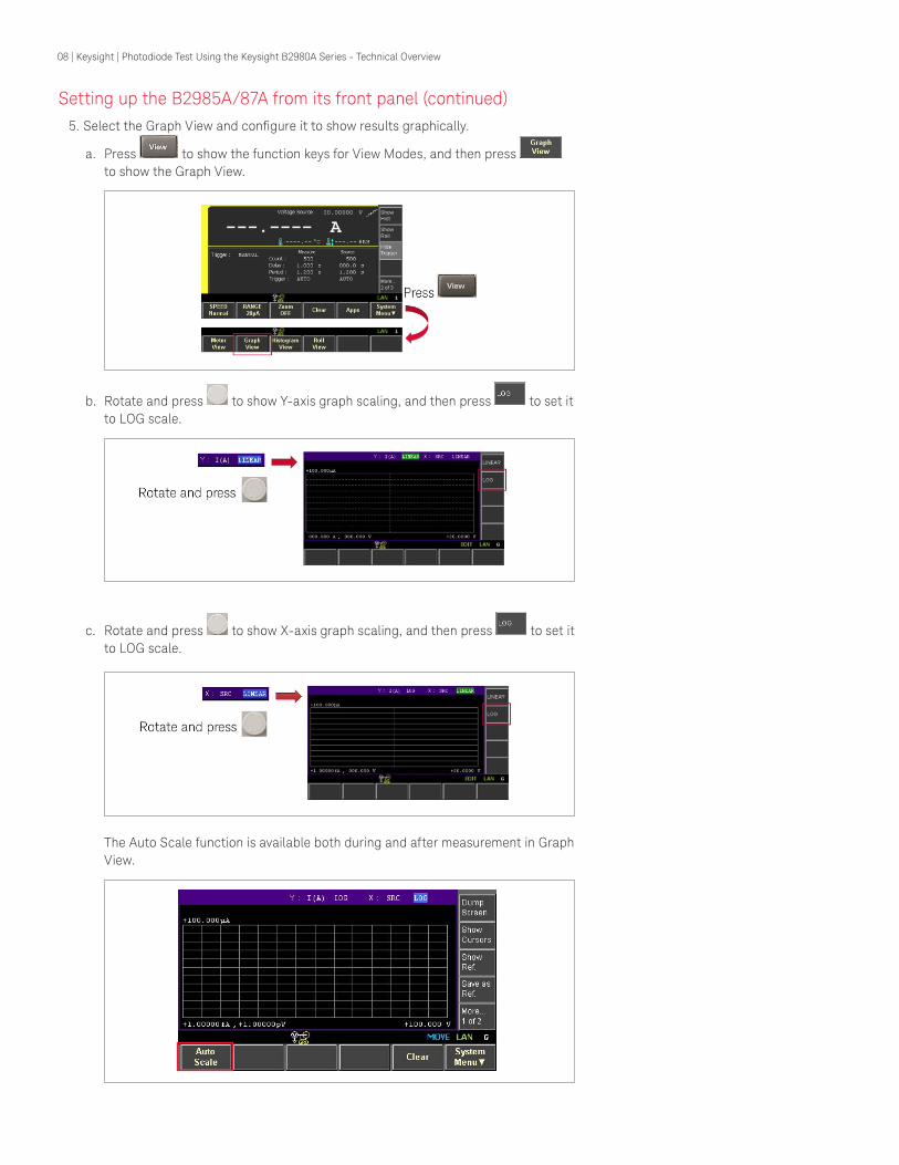
Setting up the B2985A/87A from its front panel (continued)5. Select the Graph View and configure it to show results graphically.
a. Press to show the function keys for View Modes, and then press to show the Graph View.
b. Rotate and press to show Y-axis graph scaling, and then press to set it to LOG scale.
c. Rotate and press to show X-axis graph scaling, and then press to set it to LOG scale.
The Auto Scale function is available both during and after measurement in Graph View.

09 | Keysight | Photodiode Test Using the Keysight B2980A Series - Technical Overview
Setting up the B2985A/87A from its front panel (continued)6. Enable the Voltage Source and Ammeter.
a. Press Voltage Source to enable the Voltage Source.
b. Press Ammeter to enable the Ammeter.
Controlling the B2985A/87A using SCPI commandsIf you prefer to control the B2985A/87A remotely using SCPI commands, then the follow-ing material explains how to do this.
The series of commands shown in group “A” configure measurement parameters such as measurement auto-ranging (turned off), measurement range, and aperture time, and they should be sent first. Next the series of commands shown in group “B” should be sent to set up the voltage source. Finally, the series of the commands shown in group “C” should be sent to set up the B2985A/87A’s trigger parameters.
Why is a measurement delay time required?In general, measurement paths have stray impedance that can cause leakage cur-rents and dielectric absorption when a voltage is applied. To obtain accurate results it is necessary to wait for these transients to die away before starting measurements (especially in the case of ultra-low current measurements). The required wait time for a given measurement depends on the magnitude of the applied voltage step. Larger voltage steps require longer wait times.

10 | Keysight | Photodiode Test Using the Keysight B2980A Series - Technical Overview
Performing photodiode dark current measurementsAfter configuring the instrument, perform the following procedures to execute PD dark current measurements.
If you are using the front panel, trigger the B2985A/87A to start sweeping the reverse-bias
voltage to the PD by pressing .
If you are controlling the instrument remotely using SCPI commands, then send the “:INIT (@1)” command to the instrument to start the dark current measurement.
The measurement results can be displayed on the B2985A/87A’s graphical user interface as shown in Figure 2. The Graph View function allows you examine the measurement results quickly.
The APD dark current measurements are performed by the same procedures as shown in Figure 3.
Figure 2. Photodiode dark current measurement results
Figure 3. Avalanche photodiode dark current measurement results

11 | Keysight | Photodiode Test Using the Keysight B2980A Series - Technical Overview
L-I-V Test Example
This section explains how to synchronize the B2980A Series with other instruments using the example of a laser diode (LD) L-I-V sweep test using a photodiode (PD).
Test SystemFigure 4 shows a system diagram example to evaluate the L-I-V characteristics of a LD using the B2900 Precision Instrument Family. The Keysight B2911A Precision Source/Measure Unit (SMU) is used to apply drive current to the LD and to measure the LD’s voltage. The B2911A can cover currents from 10 fA to 3 A (DC)/10.5 A (pulsed) and voltages from 100 nV to 210 V. The SMU has the capability to source and measure both positive and negative voltages and currents, so it can easily characterize the LD’s DC parameters. Since the currents supplied to the LD can be quite large, a 4-wire connec-tion (remote sensing) configuration is commonly used.
The B2985A/87A’s ammeter input terminal is connected to the PD’s anode and the B2985A/87A’s voltage source high terminal is connected to the PD’s cathode. Since the ammeter’s and voltage source’s low terminals are connected internally to the circuit common, the PD current can be measured by applying voltage to the PD from its voltage source.
In order to synchronize the B2985A/87A with the B2911A during the LD current sweep operation, a trigger signal is sent from the B2911A to the B2985A/87A. The N1294A-031 GPIO-BNC Trigger Adapter converts the B2911A’s digital I/O output to BNC outputs. The N1294A-031 allows you to synchronize the triggering of the two units using an inexpensive coaxial cable.
Figure 4. System configuration to evaluate the L-I-V Characteristics of a laser diode
12 | Keysight | Photodiode Test Using the Keysight B2980A Series - Technical Overview
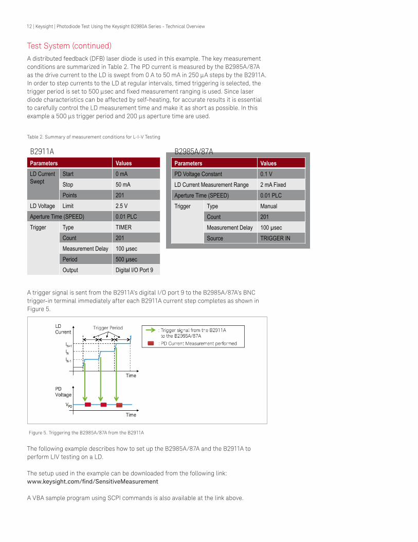
Test System (continued)A distributed feedback (DFB) laser diode is used in this example. The key measurement conditions are summarized in Table 2. The PD current is measured by the B2985A/87A as the drive current to the LD is swept from 0 A to 50 mA in 250 µA steps by the B2911A. In order to step currents to the LD at regular intervals, timed triggering is selected, the trigger period is set to 500 µsec and fixed measurement ranging is used. Since laser diode characteristics can be affected by self-heating, for accurate results it is essential to carefully control the LD measurement time and make it as short as possible. In this example a 500 µs trigger period and 200 µs aperture time are used.
Table 2. Summary of measurement conditions for L-I-V Testing
A trigger signal is sent from the B2911A’s digital I/O port 9 to the B2985A/87A’s BNC trigger-in terminal immediately after each B2911A current step completes as shown in Figure 5.
Figure 5. Triggering the B2985A/87A from the B2911A
The following example describes how to set up the B2985A/87A and the B2911A to perform LIV testing on a LD.
The setup used in the example can be downloaded from the following link: www.keysight.com/find/SensitiveMeasurement
A VBA sample program using SCPI commands is also available at the link above.
Parameters Values LD Current Swept
Start 0 mA Stop 50 mA Points 201
LD Voltage Limit 2.5 V 0.01 PLC
Trigger Type TIMER Count 201 Measurement Delay 100 sec Period 500 sec Output Digital I/O Port 9
B2911A
Aperture Time (SPEED)
Parameters Values PD Voltage Constant 0.1 V LD Current Measurement Range 2 mA Fixed Aperture Time (SPEED) 0.01 PLC Trigger Type Manual
Count 201 Measurement Delay 100 sec Source TRIGGER IN
B2985A/87A

13 | Keysight | Photodiode Test Using the Keysight B2980A Series - Technical Overview
Setting up the B2985A/87A from its front panel1. Set “Dual Measure Result Display” off to make the instrument measure only current
(if this has not already been done).
a. Open the Display Preference dialog by pressing the , , ,
function keys.
b. Press to edit “Dual Measure Result Display”. The field pointer should then be highlighted in green (EDIT).
c. Press , and then press to apply the settings.
2. Set the current measurement range operation to FIXED.
a. Press to show the Meter View function keys and then press to set the current measurement range operation to FIXED.
b. Press repeatedly until is shown on the function key. Note: In this example the 2 mA range is best because the expected maximum current is around several hundred micro amps.

14 | Keysight | Photodiode Test Using the Keysight B2980A Series - Technical Overview
Setting up the B2985A/87A from its front panel (continued)3. Select Manual Aperture Mode and set the Aperture Time
a. Press to select the manual aperture mode.
b. Press to show , where PLC stands for Power Line Cycle. 0.01 PLC is the desired aperture time in this example, which is short enough to suppress self-heating affects and long enough to provide the required accuracy.
4. Set “Triggered Voltage Source” to the desired PD voltage.
a. Hide the condensed Roll View by pressing , .
b. Rotate to select “Triggered Voltage Source” and press to edit it.c. Set the voltage value to the desired PD voltage, which is 0.1 V in this example.
Use the arrow keys to move to the digits that you want to edit.
15 | Keysight | Photodiode Test Using the Keysight B2980A Series - Technical Overview
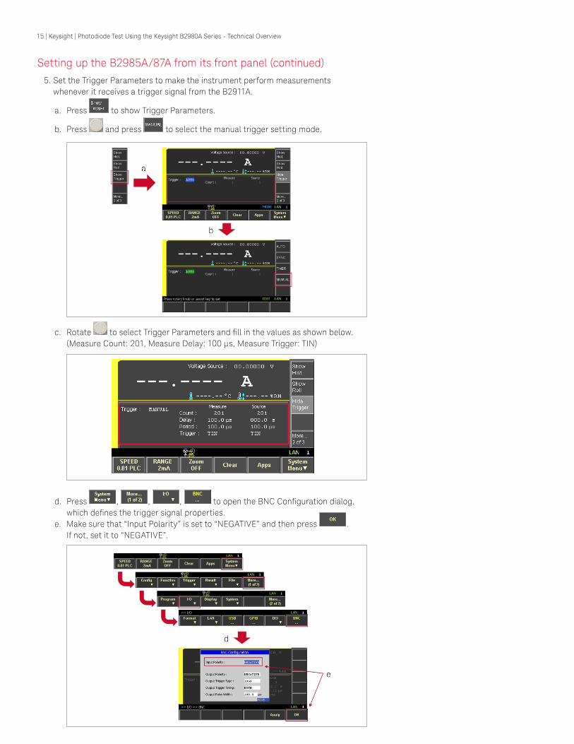
Setting up the B2985A/87A from its front panel (continued)5. Set the Trigger Parameters to make the instrument perform measurements
whenever it receives a trigger signal from the B2911A.
a. Press to show Trigger Parameters.
b. Press and press to select the manual trigger setting mode.
c. Rotate to select Trigger Parameters and fill in the values as shown below. (Measure Count: 201, Measure Delay: 100 µs, Measure Trigger: TIN)
d. Press , , , to open the BNC Configuration dialog, which defines the trigger signal properties.
e. Make sure that “Input Polarity” is set to “NEGATIVE” and then press . If not, set it to “NEGATIVE”.

16 | Keysight | Photodiode Test Using the Keysight B2980A Series - Technical Overview
Setting up the B2985A/87A from its front panel (continued)6. Enable the Voltage Source and Ammeter.
a. Press Voltage Source to enable the Voltage Source.
b. Press Ammeter to enable the Ammeter.
Controlling the B2985A/87A using SCPI commandsIf you prefer to control the B2985A/87A remotely using SCPI remote commands, then the following material explains how to do this.
The series of commands shown in group “A” configure measurement parameters such as measurement range and aperture time. Next the series of commands shown in group “B” should be sent to set up the voltage source. Finally, the series of commands shown in group “C” should be sent to set up the B2985A/87A’s trigger parameters.

17 | Keysight | Photodiode Test Using the Keysight B2980A Series - Technical Overview
Set up the B2911A via front panel operation1. Set the Source Function to Current
a. Press repeatedly until Single View for Channel 1 is shown.
b. Press and then press to set the Channel 1 Source Function to Current.
c. Press and then set the Channel 1 Source Value to 0 A.
2. Set the Voltage Limit Value
a. Press and then set the Channel 1 Limit Value to 2.5 V as shown.
3. Set the Aperture Time
a. Press , and then press to set the Aperture Time to SHORT (0.01 PLC).
4. Enable remote sensing
a. Press , , to open the Output Connection dialog.
b. Press to select Sensing Type and then press to enable remote sensing.
c. Then press to apply the changes.
18 | Keysight | Photodiode Test Using the Keysight B2980A Series - Technical Overview
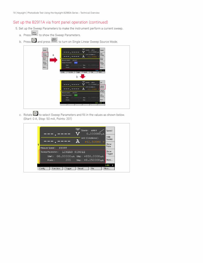
Set up the B2911A via front panel operation (continued)5. Set up the Sweep Parameters to make the instrument perform a current sweep.
a. Press to show the Sweep Parameters.
b. Press and press to turn on Single Linear Sweep Source Mode.
c. Rotate to select Sweep Parameters and fill in the values as shown below. (Start: 0 A, Stop: 50 mA, Points: 201)

19 | Keysight | Photodiode Test Using the Keysight B2980A Series - Technical Overview
Set up the B2911A via front panel operation (continued)6. Set the Trigger Parameters to make the instrument step current at regular intervals.
a. Press to show the Trigger Parameters.
b. Press and press to select Timer Trigger Setting Mode.
c. Rotate to select Trigger Parameters and fill in the values as shown below. (Measure Count: 201, Source Count: 201, Measure Delay: 100 µs, Measure Period: 500 µs, Source Count: 500 µs)

20 | Keysight | Photodiode Test Using the Keysight B2980A Series - Technical Overview
Set up the B2911A via front panel operation (continued)7. Set the Trigger Parameters to make the instrument output a trigger signal each time
the channel steps current.
a. Press , to open the Trigger Configuration dialog.
b. Press to select Layer and then press to select ACTION for Layer.
c. Rotate to select Trigger Output and fill in the entries as shown below.
d. Then press to apply the changes.
e. Press , , and then press to open the DIO Configuration.
f. Press to edit Pin # and then select to set it to Pin 9.
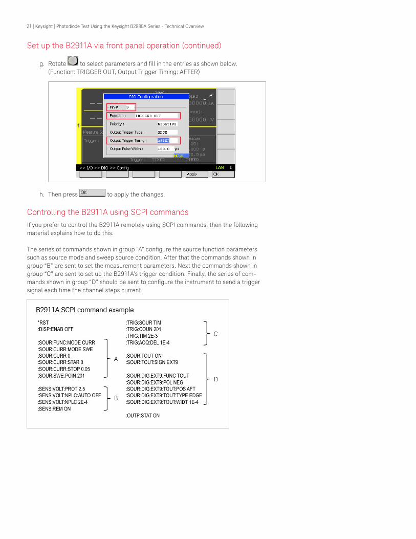
21 | Keysight | Photodiode Test Using the Keysight B2980A Series - Technical Overview
Set up the B2911A via front panel operation (continued)
g. Rotate to select parameters and fill in the entries as shown below. (Function: TRIGGER OUT, Output Trigger Timing: AFTER)
h. Then press to apply the changes.
Controlling the B2911A using SCPI commandsIf you prefer to control the B2911A remotely using SCPI commands, then the following material explains how to do this.
The series of commands shown in group “A” configure the source function parameters such as source mode and sweep source condition. After that the commands shown in group “B” are sent to set the measurement parameters. Next the commands shown in group “C” are sent to set up the B2911A’s trigger condition. Finally, the series of com-mands shown in group “D” should be sent to configure the instrument to send a trigger signal each time the channel steps current.

22 | Keysight | Photodiode Test Using the Keysight B2980A Series - Technical Overview
Perform LIV Sweep MeasurementAfter configuring each instrument, execute the following procedures to perform laser diode LIV sweep measurements.
Initiate the B2985A/87A to receive trigger signals from the B2911A by pressing ,
, , .
Initiate the B2911A to start sweeping drive current to the LD and send trigger signals
after each current step by pressing , , , .
If you prefer to initiate the instruments using SCPI commands, send an “:INIT (@1)” com-mand to the B2985A/87A first, and then send an “:INIT (@1)” command to the B2911A to start the LIV sweep measurement.
The measurement results can be seen from the graphical user interfaces of the B2985A/87A and B2911A as shown in Figure 6. The Graph View function allows you to quickly examine measurement results.
Figure 6. LD voltage and PD current measurement results

23 | Keysight | Photodiode Test Using the Keysight B2980A Series - Technical Overview
Using the instruments’ USB connections, a CSV file containing the measurement results can be exported to a flash drive and imported into a PC. This allows you to analyze the measurement results in detail using a spread sheet application and to plot the results of both the PD current and the LD current measurements as shown in Figure 7.
Figure 7. L-I-V test results
Conclusion
The Keysight B2985A/87A Electrometer/High Resistance Meter has a number of features that make it ideal for photodiode (PD) characterization. These include: a 0.01 fA current measurement resolution, a wide selection of current measurement ranges (from 2 pA to 20 mA) and a 1,000 V voltage sourcing capability that supports the evaluation of high-voltage devices such as avalanche photodiodes (APDs). These measurement capa-bilities meet virtually all existing and future low-current PD characterization needs.
Besides its impressive current and voltage specifications, the B2980A series has a num-ber of other capabilities that aid in the evaluation of PDs. One helpful feature is its 4.3" color LCD-based graphical user interface (GUI) that provides multiple options for viewing data in different formats, including graphs, histograms and trend charts. These unique front-panel capabilities facilitate the capture of transient behavior and provide the ability to make quick statistical analyses without the need for a PC.
In addition, the B2980A Series has the ability to send trigger signals to and receive trigger signals from external instruments. This makes it easy to synchronize the B2980A series with other instruments (such as the B2900A series of SMUs), which is important when performing light-current-voltage (L-I-V) sweep tests to characterize laser diodes (LDs).

For more information on Keysight Technologies’ products, applications or services, please contact your local Keysight office. The complete list is available at:www.keysight.com/find/contactus
Americas Canada (877) 894 4414Brazil 55 11 3351 7010Mexico 001 800 254 2440United States (800) 829 4444
Asia PacificAustralia 1 800 629 485China 800 810 0189Hong Kong 800 938 693India 0124 229 2010Japan 0120 (421) 345Korea 080 769 0800Malaysia 1 800 888 848Singapore 1 800 375 8100Taiwan 0800 047 866Other AP Countries (65) 6375 8100
Europe & Middle EastAustria 0800 001122Belgium 0800 58580Finland 0800 523252France 0805 980333Germany 0800 6270999Ireland 1800 832700Israel 1 809 343051Italy 800 599100Luxembourg +32 800 58580Netherlands 0800 0233200Russia 8800 5009286Spain 800 000154Sweden 0200 882255Switzerland 0800 805353
Opt. 1 (DE)Opt. 2 (FR)Opt. 3 (IT)
United Kingdom 0800 0260637
For other unlisted countries:www.keysight.com/find/contactus(BP-02-06-15)
This information is subject to change without notice.© Keysight Technologies, 2015Published in USA, March 18, 20155992-0603ENwww.keysight.com
myKeysight
www.keysight.com/find/mykeysightA personalized view into the information most relevant to you.
www.lxistandard.org
LAN eXtensions for Instruments puts the power of Ethernet and the Web inside your test systems. Keysight is a founding member of the LXI consortium.
www.pxisa.org
PCI eXtensions for Instrumentation (PXI) modular instrumentation delivers a rugged, PC-based high-performance measurement and automation system.
Three-Year Warranty
www.keysight.com/find/ThreeYearWarrantyKeysight’s commitment to superior product quality and lower total cost of ownership. The only test and measurement company with three-year warranty standard on all instruments, worldwide.
Keysight Assurance Planswww.keysight.com/find/AssurancePlansUp to five years of protection and no budgetary surprises to ensure your instruments are operating to specification so you can rely on accurate measurements.
www.keysight.com/go/qualityKeysight Technologies, Inc.DEKRA Certified ISO 9001:2008 Quality Management System
Keysight Channel Partnerswww.keysight.com/find/channelpartnersGet the best of both worlds: Keysight’s measurement expertise and product breadth, combined with channel partner convenience.
www.keysight.com/find/precisionMEASURE
24 | Keysight | Photodiode Test Using the Keysight B2980A Series - Technical Overview
Keysight B2900 Precision Instrument FamilyThe B2900 Family lines up products for both precision source and precision measurement.
www.keysight.com/find/b2900b