pheumatic nutator actuator motor - nasa · logic circuit output pressure differential ......
TRANSCRIPT

Microfiche (MFI A
PhEUMATIC NUTATOR ACTUATOR MOTOR BY
G. R. Howland
Prepared For
N A T I O N A L AERONAUTICS & SPACE A D M I N S T R A T I O N
CONTRACT N A S 3 - 5 2 1 4
I
BENDIX PRODUCTS AEROSPACE DIVISION
SOUTH BEND, INDIANA 46620
https://ntrs.nasa.gov/search.jsp?R=19650013373 2018-08-25T21:23:59+00:00Z

NOT ICE
This report was prepared as an account o f Government sponsored work. Neither t he United S ta tes , nor t h e National Aeronautics and Space Administration (NASA), nor any person ac t ing on behalf of NASA:
A.) Makes any warranty o r representat ion, expressed o r implied, wi th respect t o the accuracy, completeness, o r usefulness of the information contained i n t h i s repor t , o r t h a t t he use of any information, apparatus, method, o r process disclosed i n t h i s repor t may not in f r inge pr iva te ly owned r i g h t s ; o r
B.) Assumes any l i a b i l i t i e s with respect t o t h e use of , o r f o r damages r e su l t i ng from t h e use of any infor - mation, apparatus, method o r process disclosed i n t h i s report .
As used above, "person ac t ing on hehalf o f NASA" includes any employee o r contractor of NASA, o r employee of such contractor , t o t h e extent t h a t such employee o r cont rac tor of NASA, o r employee of such contractor prepares, disseminates, o r provides access to , any information pursuant t o h i s employment o r con- tract with NASA, o r h i s employment wi th such contractor .
Requests f o r copies of t h i s repor t should be r e fe r r ed t o
National Aeronautics and Space Administration Office of Sc ien t i f i c and Technical Information Attention: AFSS-A Washington, D.C. 20546

c
*
NASA No. C R - 5 4 3 8 2 B e n d i x No. BPAD-864-15664R
,
THIRD QUARTERLY REPORT
PNEUMATIC NUTATOR ACTUATOR MOTOR
G. R. H o w l a n d
Prepared For
NATIONAL AERONAUTICS AND SPACE ADMINISTRATION
March 31, 1965
CONTRACT NAS3-5214
TECHNICAL MANAGEMENT NASA LEWIS RESEARCH CENTER
CLEVELAND, OHIO ADVANCED DEVELOPMENT AND EVALUATION D I V I S I O N
VERNON D. GEBBEN
THE BENDIX CORPORATION BENDIX PRODUCTS AEROSPACE D I V I S I O N
SOUTH BEND, INDIANA

TABLE OF CONTENTS
SECTION 1 - SECTION 2 -
2.1 2.2 2.3
SECTION 3 - 3.1 3.2 3.3
SECTION 4 -
INTRODUCTION
MECHANICAL COMPONENTS
I n i t i a l Assembly Break-In Running Performance Measurements
COMMUTATION CIRCUIT
Logic Circuit Tests Pressure Error Valve Bistable Directional Amplifier
FOURTH OUARTER GOALS
Page 1-1 - 2-1
2-1 2-1 2-1
3-1
3-1 3-6 3-6
4-1
APPENDIX A - DISTRIBUTION LIST FOR CONTRACT NAS3-5214 QUARTERLY
APPENDIX B - DISTRIBUTION LIST FOR ABSTRACTS OF CONTRACT NAS3-5214 REPORTS A- 1
QUARTERLY REPORTS B- 1
i
, , -.
LIST OF ILLUSTRATIONS
Figure
2-1
2-2
2-3
2-4
3-1
3-2 (a)
3-2 (b)
3-3
3-4
3-5
Title
Pressure Profile - Bellows It1 and #5 Mechanical -
Commutator
Output Torque Versus Input Speed
Corrected Output Torque Versus Input Speed
Reversed Stall Torque
Commutation Plate Test Setup
Logic Circuit Output Pressure Differential
Logic Circuit Output Pressure Level
Test Setup for Model Directional Amplifier
Low Pressure Pressure Recovery
High Pressure Pressure Recovery
Page - 2-3
2-4
2-5
2-6
3-2
3-4
3-5
3-7
3-9
3-10
ii

4
PNEUMATIC NUTATOR ACTUATOR MOTOR
BY
G. R. Howland
ABSTRACT
This is t h e t h i r d quar te r repor t of a twelve-month program t o design, f a b r i c a t e and t e s t a prototype pneumatic nuta tor actuator motor f o r drum control of a nuclear reac tor .
During the th i rd quar te r , both t h e mechanical components and t h e f l u i d log ic c i r c u i t were assembled and tes ted . Performance of the motor, operated by a mechanical commuta- t i o n system, is described. The r e s u l t s of t he log ic c i r c u i t optimization program is a l s o given.

c
PNEUMATIC NUTATOR ACTUATOR MOTOR
G . R. Howland
SUMMARY
This repor t descr ibes t h e t h i r d qua r t e r accomplishments o f a twelve-month program t o develop a pneumatic ac tua tor motor of a new concept. produces a high torque, low speed mechanical output proport ional t o a pneumatic input pressure d i f f e r e n t i a l s igna l . t h e motor is accomplished by closed loop f l u i d in t e rac t ion (vortex type) devices ,
The ac tua to r motor operates from a pneumatic power supply and
The commutation log ic of
The mechanical components of t he motor were assembled and t e s t ed . Commutation was accomplished by a mechanical valving assembly which was ex te rna l ly driven. var ious input speeds, improving t h e motor performance .
The maximum obtainable torque was measured f o r A discussion is given of poss ib le methods of
I n i t i a l t e s t i n g and adjustment of t h e complete commutation log ic c i r c u i t is described. t h a t the c i r c u i t w i l l be capable of operat ing and con t ro l l i ng t h e motor.
Measurements o f t h e log ic c i rcui t output i nd ica t e s
The an t ic ipa ted goals f o r t h e fou r th and f i n a l qua r t e r are l is ted.

SECTION 1
INTRODUCTION
The Pneumatic Nutator Actuator Motor i s being developed by Bendix Products Aerospace Division under Contract NAS3-5214 f o r NASA-Lewis Research Center. and evaluate a pneumatic actuator motor f o r control of a nuclear reactor . Contract NAS3-5214. conventional gear, vane o r pis ton type ac tua tors , required t o operate the motor have no moving p a r t s and are composed of f l u i d in te rac t ion (vortex type) devices.
The purpose of the contract is t o bui ld
The required performance is given i n the spec i f ica t ions of The motor i s of a d i f f e r e n t concept from t h e
The log ic c i r c u i t s
During t h e t h i r d quarter , t he mechanical components of t he ac tua tor hardware were assembled and t e s t ed . by means of a mechanical commutation valving driven external ly .
The motor was operated
The pure f l u i d commutation p l a t e s were assembled and tes ted . Optimization of t he bleed o r i f i c e s i z e s was obtained.
Section 2 ou t l ines the present s t a t u s of t he mechanical Section 3 describes the s t a t u s of t he commutation components,
c i r cu i t ry . The fourth quar te r goals are given i n Section 4.
1-1

.
SECTION 2
MECHANICAL COMPONENTS
2.1 INITIAL ASSEMBLY
The actuator motor mechanical components were initially assembled to verify the assembly procedure. The only problem encountered during assembly (except for a minor bearing relief requirement) was the scram spring. friction was developed by the coils rubbing together. with the vendor, a more stringent specification was written and new springs are being manufactured.
This spring is a torsional clock type. It was found that excess After discussion
Delivery is expected about the middle of April.
For initial evaluation of the motor performance, the unit was assembled without the scram spring, torsion shaft, drum brake and dynamic seal . 2.2 BREAK-IN RUNNING
After initial assembly and adjustment, the motor was run continuously at an input commutation speed of 1000 rpm (5.6 rpm output speed) for fifteen minutes in each direction. On dis- assembly some flaking of the molybdenum disulphide lubricant on the gear teeth was noted. After approximately ten hours of running, mostly under high load condition, no further flaking of the lubricant was evident and the gear teeth appear in excellent condition.
No output load was applied.
2.3 PERFORMANCE MEASUREMENTS
After run-in, the pressures supplied to the bellows were monitored by gages on the mechanical commutator. It was found that the commutator was "breaking before making1', causing the number of pressurized bellows to vary between three and four, depending on the angular position of the commutator. The distribution slot in the commutator was modified to provide a more even pressure distribution. Figure 2-1 shows the pressure
2-1

variations in bellows #1 and # 5 . It can be seen that the reduction in one bellows pressure is accompanied by a corresponding increase in the other bellows pressure. and vent ports of the commutator are "short circuited" during portions of the commutation cycle. This short circuit causes an increase in the supply flow and a consequent reduction in the bellows pressure. reduction can be seen in Figure 2-1 each time a bellows is pressurized, Unsuccessful attempts were made to add capacitance to the inlet and bellows supply lines to minimize this pressure variation.
In order to obtain this symmetry, the supply
This
Maximum output torque for a given commutator speed was determined by loading the output shaft until the gear teeth disengaged. A plot of maximum output torque against input commutator speed is shown in Figure 2-2. Output shaft speed can be obtained by dividing the input speed by 180 .
This method of shaft loading will indicate the torque obtained when the pressurized bellows pressure is at a minimum. transient bellows pressure and measuring the minimum obtained, the output torque can be corrected to determine the actuator performance assuming a uniform bellows pressure. shown in Figure 2-3. which could be obtained with the self-commutation circuit.
By monitoring the
This corrected torque versus speed curve is The corrected curve indicates the maximum torque
The torque required to back drive the motor was found by holding the mechanical commutator stationary and applying sufficient torque to the output shaft to cause tooth disengagement. Figure 2-4 for various combinations of pressurized bellows.
This torque is shown in
Previous experience with nutator gear concepts has shown that the mechanical efficiency (n) is independent of the direction of drive. efficiency can be calculated from the output torque (To) and the back driving torque (Tr) as follows:
The
2-2

.
0
, i
. ._ . . - , - > ...., . . ::: ,.. !.
I
. ~ . , . ~, ,
..: -16- - ' - _
2-3

n Q) k 3 VI VI
E x d
m F VI
g d d a m
d N br 9 M CJ
0 4 snresSoig aaaeur “0. . 0 d d d 6 I I I
cpunod t p u ~ 2 : : d d 9 d N
OI 9 d
N 0 00 0 0 0 0
0 0 N d
0 ’0 d d
0 0 0 4
0 .O Q,
0 0 00
0 0 b
0 .O 9
0 .O v)
0 .O d
0 ’0 M
0 0 N
0 0 4
0
n
U E a Q, 0) a v)
w 3 a E U
P w w a m
s 5 a
w
3 s E O
CJ I N
LL
anbsoj andang

. 0 0 00 4
0 0 f- 4
0 0 \o 4
0 0 v1 rl
0 0 f 0 0 M
t d
0 0 cy rl
0
d n 2 0 k 0 - 0 - 3
53,
a3 a o w 0 m + r
G o u 0 00
0 z 0 0 \o
0 0 v1
0 0 d
0 0 M
0 0 cy
0 2
3
rr) 1
(Y
2-5

x - Clockwise Rotation o - Counterclockwise Rotation
-
-
-
-
Bellows Sup ly Pressure - 70 psig (48 x 10-8 newtons/meted)
6.38
489 in.lb. average
5.80
5-22
4.64
550
0
500
I I 1 1 1 1 1 1
450 al 3 ’ 400
350 4 4.06
FIGURE 2-4 REVERSED STALL TORQUE
2-6

c
or , from Figures 2-3 and 2-4,
This e f f i c i ency agrees c lose ly with t h e o r ig ina l design estimate (68%).
versus supply pressure cha rac t e r i s t i c s , but was terminated when a rapid de t e r io ra t ion i n output torque was noted. t h a t a l l four f lexure p ivo t s were e i t h e r broken o r badly d i s to r t ed . I t is f e l t t h a t a f a i l u r e of t he pivots resu l ted from t h e shock loading employed by t h e method of tes t and is not i nd ica t ive of t h e performance under normal operation. The pivot holes were rebored t o take l a rge r flexure pivots.
Further t e s t i n g of the motor was s t a r t e d t o determine t h e torque
Disassembly of t h e u n i t showed
This w i l l increase the torque capac i ty by 50%.
The maximum corrected output torque obtained was 2.89 meter-kilograms (250 in . lbs.) (see Figure 2-3). With a measured e f f i c i ency of 71.5%, t h e i n t e r n a l torque developed is 4.05 meter-kilograms (350 in. lbs.). The design in t e rna l torque is 7.05 meter-kilograms (610 in. lbs.) . I t appears t h a t t h e motor is producing only 57% of t h e design value. This torque reduction can be caused by one or more of t h e following fac tors .
(a) Bellows pressure is measured upstream o f a 1.015 x 10⁻³ meter (,040 inch) diameter o r i f i c e , would reduce t h e actual bellows pressure below the measured value .
Any appreciable bellows leakage
(b) Bellows e f f e c t i v e area is less than t h e design requirements.
(c) The nuta t ion angle i s incor rec t ly set.
(d) Inaccuracies i n gear p ro f i l i ng has r e su l t ed i n a reduced angle of force centroid.
2-7

To inves t iga te these poss ib le causes, t h e following ac t ion was taken:
(a) A bellows tes t f i x t u r e was fabr ica ted t o allow p res su r i za t ion of an individual bellows assembly. showed t h a t only two of t h e s ix t een on hand (e ight spare) had appreciable leakage. had neg l ig ib l e leakage.
A check of a l l the bellows
The e igh t bellows taken from t h e motor
(b) Two bellows were se lec ted a t random and t h e force f o r a given applied pressure was measured. The fo rce measurement gave an e f f ec t ive bellows area of 2.67 x 10⁻⁴ meters2 (.414 in.2) and 2,65 x 10⁻⁴ meters2 (.411 in ,2) . These areas are within t h e allowable l i m i t of 2,80 x 10⁻⁴ meters2 35% (,435 in.2 3 5 % ) .
(c) G (d) The nuta t ion angle and t h e gear p r o f i l e cannot be measured
d i r e c t l y and any ind i r ec t measurement is open t o question. After r e p a i r o f t he f lexure p ivots , it is expected t h a t t h e motor w i l l be operated with t h e pure f l u i d commutation c i r c u i t . Shims w i l l be added a t t h e ou te r casing junct ion and under t h e pivot po in t s t o vary t h e nuta t ion angle, The optimum nu ta t ion w i l l then be determined by t h e angle which r e s u l t s i n maximum output torque.
The repaired actuator motor is p resen t ly being assembled. The commutation pressure pick-offs w i l l be ad jus ted f o r operat ion with t h e pure f l u i d c i r cu i t ry .
2-8

.
SECTION 3
COMMUTATION C I RCUIT
3.1 LQGIC CIRCUIT TESTS
The commutation c i r c u i t p l a t e s shown i n Figure 3-7 of t h e Second Quarterly Report (reference NASA CR-54282) were assembled with the appropriate test p l a t e s and funct ional ly checked. leakage occurred both r a d i a l l y between t h e p l a t e s and a x i a l l y along the b o l t holes. The leakage also changed after disassembly, making it d i f f i c u l t t o size t h e f ixed o r i f i c e s f o r t h e s e l ec to r and power valve supply pressures.
A l a rge amount of
The bellows pressures could, however, be sequenced i n t h e proper order and t h e operation of t h e logic c i r c u i t was ve r i f i ed , and grease were used f o r sea l ing purposes, but it was found t h a t Krylon prevented easy separat ion of t he p l a t e s and grease contaminated t h e flow channels. being used, is t o lap and s i l v e r p l a t e a l l p l a t e s before assembly. photograph of t he p l a t e assembly i s shown i n Figure 3-1,
"Krylon"
The method found most successful, and present ly A
The bleeds were re-manifolded so t h a t the supply pressures are i n series rather than i n pa ra l l e l , from a common plenum. model commutation c i r c u i t had indicated t h a t a s e r i e s o r i f i c e arrange- ment provided the most optimum bellows pressures ,
Test on the
Many attempts were made t o optimize the bleed sizes used t o obtain these pressures. below:
The e f f ec t s of various changes are summarized
CAUSE
(1) Decrease i n se l ec to r valve bleed size.
EFFECT - Improves m i n i m but reduces maximum bellows pressure,
3-1

i
b cn w
w s a

CAUSE
(2) Increase i n size of power valve bleeds.
- EFFECT
Improves maximum but increases minimum bellows pressure . -
(3) Increase i n size of pick-off bleeds.
Improves bellows pressure d i f f e r e n t i a l
Reversing t h e bleed sizes has t h e opposite effect. I t was extremely d i f f i c u l t t o find an optimum combination of t h e bleeds. Consequently, two new t e s t p la tes were fabr ica ted making it poss ib le t o simulate a l l bleeds externally by hand valves. These valves made it much eas i e r t o set up the optimum point, and i n t h e f i n a l ana lys i s , t h e pressure-flow cha rac t e r i s t i c s can be measured t o determine equivalent bleed sizes. The t e s t p l a t e s were lapped and assembled with t h e commuta- t i o n p la tes . By spot checking several po in ts i n t h e commutation c i r c u i t , ad jus t ing t h e hand valves, and rechecking the points, an optimum s e t t i n g of t h e valves was obtained and data were recorded f o r each s t e p of t h e commutation c i r c u i t . The performance of t h i s c i r c u i t i s shown i n Figures 3-2(a) and 3-2(b) .
Figure 3-2(a) ind ica tes the average pressure d i f f e r e n t i a l obtained between t h e four pressurized outputs and t h e four non-pressurized outputs f o r each sequence of pick-off pressure. pressure levels of t h e pressurized and non-pressurized outputs.
Figure 3-2(b) shows t h e average
I t can be seen t h a t t h e pressure d i f f e r e n t i a l was a maximum when t h e four pressure pick-offs were covered, and a minimum when t h e pick- o f f s were open. d i r ec t iona l s igna l was applied (PDR Hi). va r i a t ion i n t o t a l flow applied t o each of t h e s e l e c t o r valves. flow va r i a t ion caused a change i n t h e s e l e c t o r supply pressure, which i n t u r n a f fec ted the a b i l i t y of t h e s e l e c t o r output t o control t h e power valve .
This was p a r t i c u l a r l y noticeable when t h e r i g h t This va r i a t ion was due t o t h e
The
3-3

\
o x x x
o o x x
0 0 0 %
0 0 0 0
x o o o
X X O O
X X X O
X X X % /
x x o o
% O O O
o o o o [ g
0 o o x p
O O K X ...-' X W K X
3-4

1 0 cy m I
\ o x x x
O O X X
0 0 0 %
0 0 0 0 ,
3 4 0 0 0
x x o o
X X X O
x x x o
1::: 0 0 0 0
0 0 0 %
X X K X J
I I
K O
3-5

Considerable improvement i n t h e pressure d i f f e r e n t i a l va r i a t ion can be obtained by employing a vortex pressure regula tor across the se l ec to r supply. performance of t h e complete actuator motor has been determined, commutation c i r c u i t , adjusted t o give the performance shown i n Figure 3-2, w i l l be used t o operate the ac tua tor motor.
I t is not proposed t o attempt t h i s modification u n t i l The
3.2 PRESSURE ERROR VALVE
No fur ther work beyond t h a t reported i n t h e Second Quarterly Report was performed on t h e pressure e r r o r valve. valve w i l l be done when the t o t a l system performance has been evaluated.
The s i z ing of t h i s
3.3 BISTABLE DIRECTIONAL AMPLIFIER
A b i s tab le f l i p - f lop was obtained from t h e Bendix Research Laboratories Division f o r evaluation. t o determine t h e performance of a typ ica l f l i p - f lop under conditions of high supply and high vent pressures. 10.3 x 10⁴ newtons/meter2 (15 psig) and 131 x 104 newtons/meter2 (190 psig) sup l y pressures.
pressure. valves .
The purpose of t h e tests was
Tests were conducted with
In both cases, the re i s approximately a 10.3 x 10 i newtons/meter2 (15 ps i ) drop from supply pressure t o rece iver
The control po r t s were pressurized slowly by manually operated
Figure 3-3 is a flow diagram of the test setup, S t r a in gage-type
Points 3 and 6
pressure transducers were used. and control pressures of t h e amplifier a t s i x d i f f e r e n t operating points . Supply pressure remained constant throughout t e s t ing . involve control flow continuing i n t o the amplif ier after t h e main stream has changed posit ions, The control flow occurring at t h i s point was determined by maintaining t h e control port hand valve a t exac t ly the same posi t ion as it was when the b i s t ab le valve was at t h e threshold of switching.
Figure 3-4 i l l u s t r a t e s t he rece iver
3-6

Atmos , Atmos ,
Rec ,
I I I I I Left Rinht 1 Receiver Receiver
/
Ret ,
I Left RiQht I
GN2 -# , dhfrnt Contro 1 Right
Rec, Rec t ,
Rec. - Recorder P,T, - Pressure Transducer
Atmos. - Atmosphere
FIGURE 3-3 TEST SETUP FOR MODEL DIRECTIONAL AMPLIFIER
3-7

It can be seen from Figure 3-4 that the receiver recovery pressures are 40% ofthe quantity, supply pressure minus vent pressure. recovery was determined by slowly increasing both the receiver impedances at the same time until the amplifier began to oscillate. At this point, both impedances were reduced slightly until the amplifier stabilized. The pressures that appear in Figure 3-4 are the maximum stable pressures obtainable .
Pressure
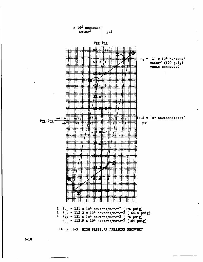
During the high pressure test, the vents were connected to each other and shut off from the atmosphere so that better pressure recovery could be maintained. Figure 3-5 illustrates the results of this test.
A test run with 138 x 104 newtons/meter2 (200 psig) supply pressure, 121 x 104 newtons/meter2 (175 psig) maximum and 113 x 104 newtons/rneterZ (165 psig) minimum receiver pressures was made to check the weight flow rate through the amplifier. The supply flow rate was .00042S kilograms/ second (.00094 lb./sec.) GN2. The high side receiver flow was ,000226 kilograms/second (.0005 lb./sec.) . The commutation circuit requires a high side flow of approximately ,00454 kilograms/second (-01 lb./sec.) GN2, a weight flow rate twenty times greater than transmitted by the tested amplifier.
It is believed the amplifier can be scaled to meet the higher flow requirements and yet maintain the 121 x lo4 newtons/meter2 (175 psig) high side, 113 x 104 newtons/meter2 (165 psi ) low side pressures with a supply pressure of 138 x 104 newtons/meterg (200 psig).
The pressure-flow characteristics of the directional signal in the actual commutation will be measured to determine more precisely the requirements before a bistable unit is fabricated.
3-8

PCL-PCR
PRR-PRL x lo3 Newtons/
meter2 ._ - 1 psi
Psupply 10e3~104 Meter2 (I
Pvmt - 0
-48.3' -7 a Pu = 41,4 x 10³ newtons/meterZ (6,O psig)
PCR - 2.76 x 10³ nswtons/meterZ (-0.4 psig) @ PRR = 41.4 x 10³ newtons/meter2 (6.0 psig)
PCL - -2,76 x 10³ newtons/meter2(-0,4 psig)
FIGURE 3-4 LOW PRESSURE PRESSURE RECOVERY
newtons/ ter2
3-9
\
meter2
-4 1 -
p s i
*S
1.4 x
.,.. . . . . . . . . . . . . . . . . . . . . . . . . . . . . . . . . . . . . ,._. .... _... . ._. . . . . . . . . . . . . . . . . . . . . . . . . ..-. I 1 L ' . . . . . . . . . . . . . . . . . . . . . . . . . . . . . . . . . . . .
p s i
131 x 104 newtons/ meter2 (190 psig) vents connected
x lo4 newtons/meter2 (176 psig) 2 x 10⁴ newtons/meter2 (164.8 ps ig ) x 104 newtons/meter2 (176 psig) 9 x 10⁴ newtons/meter2 (164 ps ig )
103 newtons/meter 2
F I G U R E 3-5
3-10
H I G H PRESSURE PRESSURE RECOVERY
SECTION 4
FOURTH QUARTER GOALS
The in tegra t ion of t h e commutation c i rcui t and t h e ac tua tor motor w i l l be made e a r l y i n t h e four th quarter. pick-off pos i t ions w i l l then be adjusted t o obta in optimum performance. Once the completed system is optimized, flow measurements w i l l be made t o determine t h e requirements of the pressure e r r o r valve and t h e d i r ec t iona l f l i p - f lop , These u n i t s w i l l then be fabr ica ted , t e s t e d and incorporated with t h e ac tua tor motor system.
The nuta t ion angle and t h e
An electromechanical torque motor of t h e NERVA drum actuator design w i l l be used t o provide the input signal. t i o n c i r c u i t r y , dynamic response measurements w i l l be made.
Upon completion of t h e commuta-
The complete ac tua to r motor w i l l be connected t o t h e NERVA drum f i x t u r e and operated on hydrogen gas a t a gas and environmental temperature down t o -280°F. t h e cryogenic temperatures.
Operation of the scram mechanism w i l l be demonstrated a t
Due t o t h e f ab r i ca t ion lead time, it i s not an t i c ipa t ed t h a t t h e d i r ec t iona l ampl i f ie r o r pressure e r r o r valve w i l l be evaluated at cryogenic conditions. commutation log ic should, however, i nd ica t e t h e f e a s i b i l i t y of t h e e n t i r e system .
The operation of t h e remaining components of t h e
An ana ly t i ca l study of t h e comparison between t h i s ac tua tor motor and more conventional concepts has been s t a r t ed . The performance d a t a obtained during t h e four th quarter w i l l be incorporated i n t h i s study.
4-1

APPENDIX A
DISTRIBUTION L I S T FOR
CONTRACT N A S 3 - 5 2 1 4 QUARTERLY REPORTS

NASA-Lewis Research Center (3) 21000 Brookpark Road Cleveland, Ohio 44135 Attention: Vernon D. Gebben
NASA-Lewis Research Center (2) 21000 Brookpark Road Cleveland, Ohio 44135 Attention: Lewis Library
NASA-Lewis Research Center (1) 21000 Brookpark Road Cleveland, Ohio 44135 Attention: James E. Burnett, Technology
Ut i l i za t ion O f f ice
NASA-Ames Research Center (1) Moffett Field, Cal i fornia 94035 Attention: Library
NASA-Goddard Space F l ight Center (1) Greenbelt, Maryland 20771 Attention: Library
NASA-Marshall Space F l ight Center (2) Huntsvi l le , Alabama 35812 Attention: Library
NASA-Marshall Space Fl ight Center (1) Huntsville, Alabama 35812 Attention: Michael A, Kalange,
R- ASTR-NF
NASA-Western Operations (1) 150 Pic0 Boulevard Santa Monica, Cal i forn ia 90406
NASA S c i e n t i f i c 6 Technical Information
Box 5700 Bethesda, Maryland Attention: NASA Representative
Facil i ty (6 & Reproducible)
NASA-Lewis Research Center (1) 21000 Brookpark Road Cleveland, Ohio 44135 Attention: C. J. Shannon
NASA-Lewis Research Center (1) 21000 Brookpark Road Cleveland, Ohio 44135 Attention: Lewis Technical
Information Division
NASA Headquarters (1) Washington, D.C. 20546 Attention: F. C. Schwenk, NPO
NASA-Flight Research Center (1) P.O. Box 273 Edwards, Cal i forn ia 93523 Attention: Library
NASA-Langley Research Center (1) Langley S ta t ion Hampton, Virginia 23365 Attention: Library
NASA-Marshall Space F l ight Center (3) Huntsvil le, Alabama 35812 Attention: Roy E. Currie, Jr.
R-ASTR-TN
NASA-Manned Spacecraft Center (1) Houston, Texas 77001 Attention: Library
Jet Propulsion Laboratory (1) 4800 Oak Grove Drive Pasadena, Cal i forn ia 91103 Attention: Library
Harry Diamond Laboratories (3) Washington 25, D.C. Attention: Joseph M. Kirshner
A-1

Harry Diamond Laboratories (2) Washington 25, D.C. Attention: Library
Wright-Patterson Air Force Base (2) Ohio Attention: Library
U. S. Atomic Energy Commission (3) Technical Information Service Extension P.O. Box 62 Oak Ridge, Tennessee
NASA-Lewis Research Center (2) 21000 Brookpark Road Cleveland, Ohio 44135 Attention: Nuclear Rocket Technology
Off ice
NASA Headquarters (1) Washington, D.C. 20546 Attention: John E. Morrissey, NPO
Army Missile Command (2) Redstone Arsenal, Alabama Attention: Library
U. S. Atomic Energy Commission (3) Technical Reports Library Washington, D.C.
Los Alamos S c i e n t i f i c Laboratory (1) Los Alamos, New Mexico Attention: Joseph Perry, N-4
NASA Lewis Research Center (1) 21000 Brookpark Road Cleveland, Ohio 44135 Attention: Alan S. Hintze, SNPO
Case I n s t i t u t e of Technology (1) Mechanical Engineering Department Cleveland, Ohio Attention: Prof. Charles Taft

n
APPENDIX B
DISTRIBUTION LIST FOR ABSTRACTS OF
CONTRACT NAS3-5214 QUARTERLY REPORTS

NASA-Lewis Research Center (10) 21000 Brookpark Road Cleveland, Ohio 44135 Attention: Vernon D. Gebben
NASA Headquarters (1) Washington, D.C. 20546 Attention: Iierman H. Lowell, R E I
NASA-Marshall Space Fl ight Center (10) Huntsvil le, Alabama 35812 Attention: Roy E. Currie, Jr.; R-ASTR-TN
NASA-Marshall Space F l ight Center (1) Huntsvil le, Alabama 35812 Attention: Je ro ld Peoples, R-ASTR-NFM
Harry Diamond Laboratories (20) Washington 25, D.C. Attention: Joseph M. Kirshner
Army Missile Command (5) Redstone Arsenal, Alabama Attention: William A. G r i f f i t h
Army Missile Command (1) Redstone Arsenal, Alabama Attention: B. J. Clayton
Army Transportation & Research Command (1) F t . Eust is , Virginia Attention: George W. Fosdick
Bolling Air Force Base (1) Washington, D.C. 20332 Attention: Major C. R. Wheaton
Wright-Patterson A i r Force Base (1) Ohio Attention: James F. Hall
NASA Headquarters (1) Washington, D.C. 20546 Attention: John E. Morrissey, NPO
NASA-Langley Research Center (1) Langley S ta t ion Hampton, Virginia 23365 Attention: Harvey V. Fu l l e r
NASA-Marshall Space F l ight Center (1) Huntsvil le, Alabama 35812 Attention: William White, R-ASTR-TN
NASA-Marshall Space F l ight Center (1) Huntsvil le, Alabama 35812 Attention: Russel Alcott , R-ASTR-NFM
Army Material Command (1) Research Division Washington 25, D.C. Attention: Major W. T. Kerttula
Army Missile Command (1) Redstone Arsenal, Alabama Attention: T. G. Wetheral
Army Munitions Command (1) Picatinny Arsenal Dover, New Je r sey Attention: S i l v i o J. Odierno
Army Transportation & Research
F t . Eust is , Virginia Attention: Robert R. Piper
Command (1)
Kirt land A i r Force Base (1) New Mexico Attention: Capt. Charles V. Fada
Wright-Patterson Air Force Base (1) Ohio Attention: Seth A Young
B-1

Wright-Patterson A i r Force Base (1) Ohio Attention: Ronald Ringo
Office of Naval Research (1) Dept. of Navy Washington, D.C. 20360 Attention: Stanley Doroff
Bureau of Weapons (1) Munitions Building Washington 25, D.C. Attention: Richard A.Retta
Massachusetts I n s t i t u t e of Technology (1) Department of Mechanical Engineering Cambridge 39, Massachusetts Attention: Forbes T. Brown
Wright-Patterson A i r Force Base (1) Ohio Attention: Charles Bentz
Office of Naval Research (1) Washington, D.C. 20360 Attention: Ancel E. Cook
U. S. Atomic Energy Commission (1) Division o f Reactor Development Washington 25, D.C. Attention: Frank C. Legler
NASA-Lewis Research Center (2) 21000 Brookpark Road Cleveland, Ohio 44135 Attention: Nuclear Rocket Technology
Office
.
B-2