phase iidevelopment efforts
TRANSCRIPT

VERY LOW FRICTION SMALLRADIUS DOME CUTTERS
FOR PERCUSSION BITS
PHASE IIDEVELOPMENT EFFORTS
& NOVATEKPrepared by David S. Pixton
15 September 1999
DISCLAIMER
This report was prepared as an account of work sponsoredby an agency of the United States Government. Neitherthe United States Government nor any agency thereof, norany of their employees, make any warranty, express orimpJied, or assumes any legal liability or responsibility forthe accuracy, completeness, or usefulness of anyinformation, apparatus, product, or process disclosed, orrepresents that its use would not infringe privately ownedrights. Reference herein to any specific commercialproduct, process, or service by trade name, trademark,manufacturer, or otherwise does not necessarily constituteor imply its endorsement, recommendation, or favoring bythe United States Government or any agency thereof. Theviews and opinions of authors expressed herein do notnecessarily state or reflect those of the United StatesGovernment or any agency thereof.
DISCLAIMER
Portions of this document may be illegiblein electronic image products. Images areproduced from the best available originaldocument.
VERY LOW FRICTION SMALL RADIUSD O M E CUTTERS FOR PERCUSSIONBITS
PHASE IIDEVELOPMENT EFFORTS
BACKGROUND
Basic Concept
When drilling with a percussion or roller-cone bit penetration of the drill depends on its abilityto crush and crack the rock formation being drilled. Initial penetration of the formation occurs
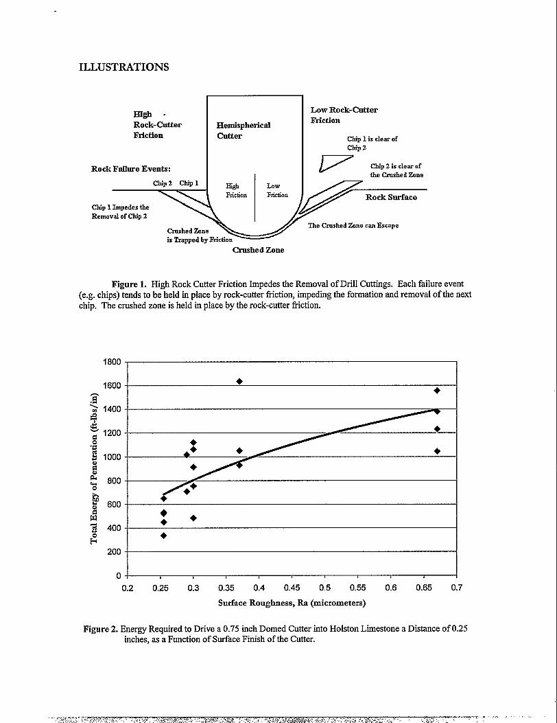
primarily by crushing of the rock beneath the cutters of the bit. As penetration continues, the crushedzone increases in size and transmits force to the surrounding rock causing cracks to form around thecrushed zone. i The crushed and cracked zones grow as the cutter continues to penetxate, creating freeparticles. Depending on the loading geometry these particles may then be liberated from the cuttingzone, or retained within it. If retained by frictional forces, they are further crushed under continuedloading and transfer energy from the bit to the underlying rock. Because of their structure this crushedzone distributes that force as the tool continues to penetrate, and effectively become a blunt extensionof the cutter.
Additional crushing of particles held under the bit by geometric and frictional constraintsabsorbs a significant portion of the energy required for penetration of the cutters. The movement ofsuch particles from the cutting zone relieves confinement on the underlying rock (which may otherwisereach pressures of over 20,000 psi), lowering its resistance and concurrently lowering the forces requiredto achieve penetration. Two approaches that increase the mobility of the cuttings under the cutter areto decrease the wedge angle of the cutter (in effect making a sharper cutter) and decrease the coefficientof fiction between the cutter and the rock formation. Both of these factors will lower cutting forcesand increase rate of penetration (ROP) regardless of other rock characteristics.
Figure 1 depicts the benefits of using a low friction cutter as opposed to a higher friction cutter.As shown, the low coefficient of friction offered by a polished cutter allows rock cuttings to beremoved more quickly than is possible with current &her fiction tools. An example of currenttechnology that corroborates this concept at least in part is a polished flat drag bit cutter patented byBaker Hughes in 1995~. This relatively new development claims increased cutting efficiency andimproved chip formation. Improved chip regulari~ indicates a lower specific energy of formation thanis possible with prior art drag bit cutters. The profile of the rock surface left behind the cutter exhibitsless relief than the profiles of prior art cutters. The surfaces of the Baker Hughes cutting elements werepolished to a mirror finish, which greatly reduces the adhesion of the chips as they form. This approachclaims to yield a higher ROP, because the cuttings move quickly away fi-om the point where they areformed. Drag bit technology, while fundamentally different from percussion drilling, still requires highstrength, high abrasion-resistant inserts for economical drilling. The super hard cutting surface was
polished to at least a 10 p inch surface variation with 0.5 p inch preferred.
2
NOVATEK 2185 SOUTH LARSEN PARKWAY, PROVO, UT 84606 (801) 374-6000

As a second benefit of reduced friction cutters, decreased fiction should decrease the thermaland mechanical loading on the cutting inserts in hard rock. Frictional heating of polycrystallinediamond inserts is destructive to the diamond coating. With decreased fiction betxveen the insert andthe rock frictional heating will decrease. Moreover, improved penetration in harder formations due tolower fiction may allow use of lower weight on biq which wd.1decrease cutter loading. Thirdly, themechanical robustness of the cutter is expected to improve as the cutter is polished. Polishing willdiminish surface imperfections that act as stress risers and crack initiation sites. Hence, the fatiguestrength of the cutters is expected to increase, resulting in a longer useful life, and less down-time due tobit failure.
It should be noted that these approaches to increasing ROP are only useful if the surface finishand sharpness are maintained over a significant portion of the life of the cutter. The only material thatis hard enough to maintain its shape and surface finish while drilling in hard, abrasive formations isdiamond. Even tungsten carbide, which is widely used in drilling, wears rapidly, causing dulling of thecutter and loss of initial surface finish.
Polycrystalline diamond (PCD) coatings have been developed to improve the wear resistance ofdrill Cutters.fiI ‘“ Such coatings have been used to great advantage in certain rotary and percussiondrilling applications. However, in har~ abrasive formations, this type of cutter still exhibits wear. Highstresses placed on diamond-to-diamond bonds (which bond diamond crystals together) cause eventualfailure of these bonds. MicroCracks occur within the coating, followed by progressive loss of thecoating in chipped regions. Moreover, industry experience has shown that the sharper the cutter, thelower the service life of the PCD coating. This is due, at least in large part to residual stresses formedwithin the cutter during the coating process. Once the coating is IOSLthe underlying tungsten carbidecutter is exposed and wear proceeds more rapidly. These factors have seriously limited the applicationof such coatings in hard rock regions, and have largely deprived such regions of the improved wearresistance and increased rate of penetration offered by PCD inserts.
Project Background
For several years, Novatek has been actively pursuing development of new diamond materials’that will extend both the life and application of diamond enhanced cutters, by allowing higher appliedstress and sharper cutting element design. To better address the problems outlined above which limithard rock application of diamon~ Novatek has focused on the development of a suite of small tip-radius (sharp), polished PCD inserts for use as percussion and roller cone cutters. This developmenteffort has required fundamental and applied research to determine the extent of benefit deriving fromreduced friction of the cutters. It has also required materials research and development to accomplishheretofore prohibitive levels of PCD cutter sharpness.
Initial fundamental studies begun in the fall of 1996, and completed at the Universiv ofMissouri Rolls’s Rock Mechanics and Explosives Research Center (UMR-RMERC), have shown thatindeed, there is a correlation between the surface roughness of the cutter and the force required topenetrate at least some rock types. Figure 2 shows these initial results for specimens of HolstonLimestone. These results suggest that for this formation, polished cutters can allow use of lower weighton bit to drill without penalizing penetration rate; conversely, at typical weight on bit levels, penetrationshould increase. Similar trends were obtained for other rock samples, including Roubidoux Sandstone,Salem Limestone, Sioux Quartzite, and Dresser Basal$ although some of the data showed inconclusiveor even slightly negative relationships.
3
NOVATIX 2185 SOUTH LARSEN PARKWAY, PROVO, UT 84606 (801) 374-6000
,,.,~f,$$~~.$:;,. *.,$:,,, . ,*>.,T V.-.. . .. . .. . .
“~:;’.”~>:;$;f&,,\ .,; > ,, . ,....<<:. .,, .: ;,, . ‘-, ,,.,
Initial studies have also shown that shaped (non-planar) polycrystalline diamond inserts can be
polished to a very good surface finish, although initial polishing attempts were quite labor-intensive, dueto the hardness of the diamond coating and the shape of the polished surface. As for the ability of thePCD coating to maintain a polish during the drilling process, repeated observation of percussion bits
populated with polycrystalline diamond coated cutters have shown that the diamond coating does notdegrade in surface finish over the period of usage. Rather, it polishes to a certain extent in the areas ofhighest contact between the cutter and the rock.
Phase II ObjectivesThe overall goal of this program is to provide industry with a new generation of diamond
enhanced drill inserts which increase rate of penetration (ROP) and bit life, and which allow use of PCDin harder rock ~es. A means of economically polishing shaped PCD inserts, coupled with materialsimprovements, are the specific mechanisms for accomplishing this overall objective.
Based on the above discussion, the primary objectives of the current research are
● to determine the diamond coating design and polishing means which will result inthe most favorable improvements in drilling rate with respect to cost.
● to catalog the effectiveness of polished inserts in a variety of rock types.
The results obtained in the pursuit of these objectives may have further implications withrespect to the design of bits for maximum penetration rate. However, at this point no dramaticchanges in bit design are anticipated as being needed to fully benefit fkom the improved cuttertechnology.
ApproachThe overall approach of this research has been to seek and apply understanding of the physical
properties and chemistry of PCD coated cutters that will lead to improvements in overall drillingefficiency. Particular attention is given to the condition of the cutter’s surface.
The surface roughness of a PCD coating is controlled both by the selection of PCD processingparameters and by post-processing techniques such as polishing the surface after the coating has beenapplied. The nature of the coating, whether single or multiple layere~ with or without interlayers, orwith coarse or fine grain size, will affect the coating’s ability to take a polish. Furthermore, theformulation of the coating has been found to have a great influence on the overall robustness of thecutter. Hence, it is necessary to consider each of the above interrelated factors when moving towardthe desired end result.
For this reason, the basic approach of the present research has been to seek concurrentimprovements in coating formulation, geometry, and surface finish. Fundamental research using rockpenetration tests and basic single cutter evaluations were used to guide initial decisions. UMR-RME.RChas played an instrumental role in this fundamental work and in providing expertise in rock failureanalysis. Initial tests are followed by validation under the more complex conditions found in actualdrilling applications. Both percussion and rotary (roller-cone) drilling have been chosen as suitablebeds for testing and introducing improved cutters. Industry interest in improvements to PCD cutters issufficient to provide for test sites as “in-kind” contributions to the research.
Final validation of the new technologies, however benefici~ must include a comparison ofcosts of additional processes to the gains achieved. Therefore, development of polishing methods thatare economically favorable has been of prime importance.
4
NOVATEK 2185 SOUTH LARSEN PARKWAY, PROVO, UT 84606 (801) 374-6000

RESEARCH RESULTS
Polishing DevelopmentsPrevious efforts to polish shaped PCD inserts yielded a high polish at a high cost. Under the
current research program, several additional methods of polishg have been ~vesu@e4 ~clu~g
traditional finishing processes such as tumbling, lapping, and grinding, as well as other more proprietaryprocesses. The best of these processes have duplicated the highest degree of polish accomplishedearlier (see Figure 2), but at much lower COSGand higher repeatability. A key to improving cost andrepeatability has been the automation of the polishing process. Figure 3 shows a proto~e machinethat has been built to polish PCD cutters, which utilizes the polishing technique just mentioned. Asshown, this machine offers several independent degrees of fkeedom for polishing convex or concaveaxisymmetric cutter shapes.1 It is capable of generating very high relative speed beween PCD cutterand the polishing whe~ which is necessary for obtaining a high polish.
Using this polishing technology, a surface finish of 0.23-0.27 micrometers @a) is currentlyachievable in less than ten minutes of polishing. This suggests that the benefits of polishing may beobtained rather inexpensively, as the process is scaled up to higher quantities. Figure 4 illustrates themirror-like finish available by this process. This finish is similar to tbe level of polish offered by acommercially available polisher for flat diamond parts. Referring again to Figure 2, such a polish couldincrease the rate of penetration of the cutter by as much as a factor of ~o or three in medium to hardrocks.
To quanti~ the actual effect of the polished cutter in a full-scale field tesg two 6-1/2 inchpercussion bits were prepared and fully populated with polished cutters. One of these bits is shown inFigure 5. The two bits were identical in geometry and polish (cutters were full rounds ‘&in diameter);however, the two varied in the diamond mix used to coat the cutters. The first bit was populated withcutters from the “A” material described below, the second was populated with “C” formulation cutters.These NO bits were run in well-bedded graphite and shale formations, with occasional suingers ofquartz. Table 1 shows the results of the bit runs of these mo bits, along with the average of five bit runswith standard PCD cutters. As shown, the two polished cutter bits did not conclusively exhibit longerlife than the standard PCD cutters. ROP data is not yet available on these wells.
PCD Cutter Type Footage, ft.
Polished “A” mix 1920I
Polished “C” mix 2290
Unpolished “A” mix (average, std. Deviation) 2390,1376 ITable 1. Performance of Polished Cutter Percussion Bits vs. Standard Cutter Bits
1 It is anticipated that ansxisymmetic shapes may also be polished on this machine with modifications to the control of theprimary spindle.
5
NOVATEK 2185 SOUTH LARSEN PARKWAY, PROVO, UT 84606 (801) 374-6000
~ .T+~ ,,7 .:, .:,2:i*f&~:;t,<;~- : ,-$;~.;,..:- >.;/:.?
A third bit has also been buil~ this time a tri-cone rock bit for oil and gas drilling. Because ofthe difficulty of obtaining test sites for new products in today’s marke~ the bit manufacturer chose theconservative approach of testing three different iterations of cutters in the same bit. Of these threeiterations, only one was polished. Hence the information to be gathered in this test will be related to lifeand survivability of the polished cutters versus the other iterations (no meaningful ROP data isexpected). The geometry of the cutters in this bit was also conservatively specified to be full radiusrounds, rather than the more aggressive shapes developed. This bit has now been out in the field for afew months, but has yet to be run due to adverse economic drivers. Once this bit is successfully run,and confidence is gained in the new cutters, it is Novatek’s intention to build a bit fully populated withpolished cutters, which will be able to yield data regarding ROP improvement.
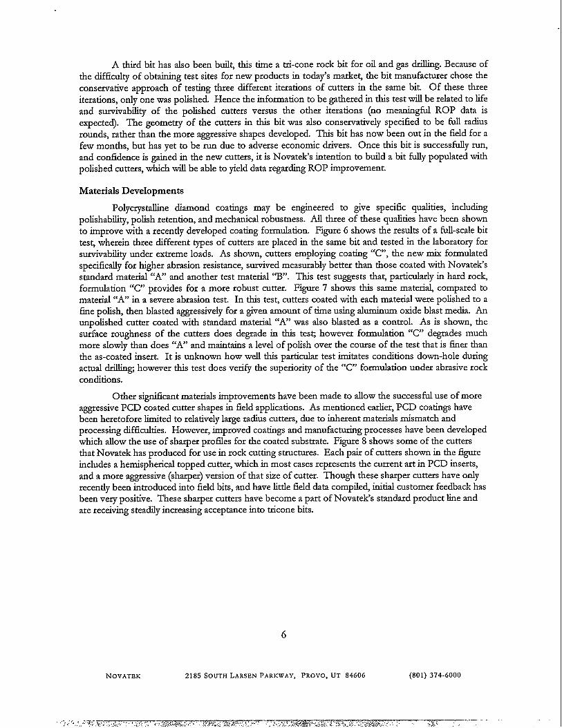
Materials Developments
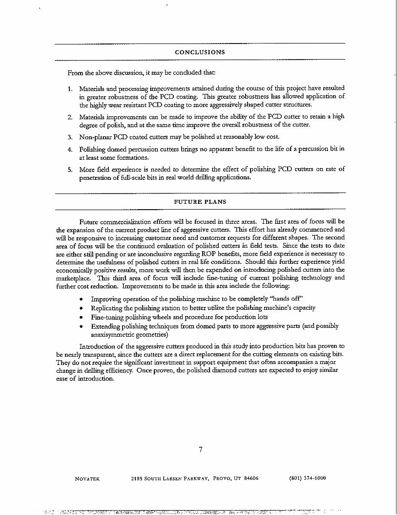
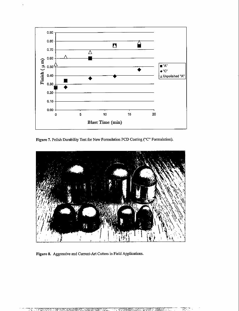
Polycrystalline diamond coatings may be engineered to give specific qualities, includingpolishability, polish retention, and mechanical robustness. All three of these qualities have been shownto improve with a recently developed coating formulation. Figure 6 shows the results of a full-scale bittes~ wherein three different types of cutters are placed in the same bit and tested in the laboratory forsurvivability under extreme loads. As shown, cutters employing coating “C”, the new mix formulatedspecifically for higher abrasion resistance, survived measurably better than those coated with Novatek’sstandard material “A” and another test material %“. This test suggests that particularly in hard rockformulation “C” provides for a more robust cutter. Figure 7 shows this same materi~ compared tomaterial “A” in a severe abrasion test. In this tes~ cutters coated with each material were polished to afine polish, then blasted aggressively for a given amount of time using aluminum oxide blast media. Anunpolished cutter coated with standard material “A” was also blasted as a contiol. As is shown, thesurface roughness of the cutters does degrade in this tes~ however formulation “C” degrades muchmore slowly than does “A” and maintains a level of polish over the course of the test that is finer thanthe as-coated insert. It is unknown how well this particular test imitates conditions down-hole duringactual drilling however this test does verify the superiority of the “C” formulation under abrasive rockconditions.
Other significant materials improvements have been made to allow the successful use of moreaggressive PCD coated cutter shapes in field applications. As mentioned earlier, PCD coatings havebeen heretofore limited to relatively large radius cutters, due to inherent materials mismatch andprocessing difficulties. However, improved coatings and manufacturing processes have been developedwhich allow the use of sharper profdes for the coated substiate. Figure 8 shows some of the cutteisthat Novatek has produced for use in rock cutting structures. Each pair of cutters shown in the figureincludes a hemispherical topped cutter, which in most cases represents the current art in PCD inserts,and a more aggressive (sharper) version of that size of cutter. Though these sharper cutters have onlyrecently been introduced into field bits, and have little field data compile~ initial customer feedback hasbeen very positive. These sharper cutters have become a part of Novatek’s standard product line andare receiving steadily increasing acceptance into tricone bits.
6
NOVATEK 2185 SOUTH LARSEN PARKWAY, PROVO, UT 84606 (801) 374-6000
CONCLUSIONS
From the above discussion, it maybe concluded that
1. Materials and processing improvements attained during the course of this project have resultedin greater robusmess of the PCD coating. This greater robustness has allowed application ofthe highly wear resistant PCD coating to more aggressively shaped cutter structures.
2. Materials improvements can be made to improve the ability of the PCD cutter to retain a highdegree of polish, and at the same time improve the overall robustness of tbe cutter.
3. Non-planar PCD coated cutters maybe polished at reasonably low cost.
4. Polishing domed percussion cutters brings no apparent benefit to the life of a percussion bit inat least some formations.
5. More field experience is needed to determine the effect of polishing PCD cutters on rate ofpenetration of full-scale bits in real world drilling applications.
FUTURE PLANS
Future commercialization efforts will be focused in three areas. The first area of focus will bethe expansion of the current product line of aggressive cutters. This effort has already commenced andwill be responsive to increasing customer need and customer requests for different shapes. The secondarea of focus will be the continued evaluation of polished cutters in field tests. Since the tests to dateare either still pending or are inconclusive regarding ROP benefits, more field experience is necessary todetermine the usefi-dness of polished cutters in real life conditions. Should this further experience yieldeconomically positive results, more work will then be expended on introducing polished cutters into themarketplace. This third area of focus will include fine-tuning of current polishing technology andfurther cost reduction. Improvements to be made in this area include the following
. Improving operation of the polishing machine to be completely “hands off”
. Replicating the polishing station to better utilize tbe polishing machine’s capacity
● Fine-tuning polishing wheels and procedure for production lots
. Extending polishing techniques from domed parts to more aggressive parts (and possiblyanaxisymmetiic geometies)
Introduction of the aggressive cutters produced in this study into production bits has proven tobe nearly transparen~ since the cutters area direct replacement for the cutting elements on existing bits.They do not require the significant investment in support equipment that often accompanies a majorchange in drilling efficiency. Once proven, the polished diamond cutters are expected to enjoy similarease of introduction.
NOVATIX
7
2185 SOUTH LARSEN PARKWAY, PROVO, UT 84606 (801) 374-6000
References
i Verhoef, P.N.W., Ockeleon, JJ., and van Kesteren, W. G.M., 1996, “The Significance of rock Ductility for Mechanical RockCutting.” In Aubertin, M., Hass@ F., and M@ H., eds., Rock Mechaniu Took andTechnique.r,A.A. Balkem~ pp. 709-716.
U. Lund, J. and Smith R. “Superhard Cutting Element Having Reduced Surface Roughness and Method of Modifying.” USPatent 5,447,208 (Sep. 5, 1995).
iii. McCarty, L. H. “Diamond Enhanced Inserts Create Superior Drill Bi~” DewgnNezm (Jan. 5, 1987).
ivEc~~om, D. “Bifi ~th Diarnond.Coated Inserts reduce Gauge Problems.” OiiandGa.rJonmal (June 17, 1991), pp. 41-43.
‘. Hall, H. T., Jr., and D. R Hell. “Carbide/Metal Composite Material and a Process Therefor.” US Patent 5~04,342 (Apr. 19,1994).
8
NOVATEK 2185 SOUTH LARSEN PARKWAY, PROVO, UT 84606 (801) 374-6000
ILLUSTRATIONS
H@ -Rock-CutterFriction
Rock Failure Events:
chip 2 chip 1
HemisphericalCutter
mFriction
LOWFriction
Removal of Chip 2
-,.-is Trapped by Friction
Low Rock-CutterFriction
Chip 1 is clear ofChipz
vChip 2 is clear ofthe Crnshed Zme
The Crnshed Zone can Escape
Crushed Zone
Figure 1. High Rock CutterFriction Impedes the Removal of Drill Cuttings. Each failure event(e.g. chips) tends to be held in place by rock-cutter fiction, impeding the formation and removal of the nextchip. The crushed zone is held in place by the rock-cutter fiction.
.. .. ..----
I /’ &
I +++
0.2 0.25 0.3 0.35 0.4 0.45 0.5 0.55 0.6 0.65 0.7
Surface Roughness, Ra (micrometers)
Figure 2. Energy Required to Drive a 0.75 inch Domed Cutter into Holston Limestone a Distance of 0.25inches, as a Function of Surface Finish of the Cutter.

.
Figure 3. Prototype Polishing Machine for Shaped PCD Cutters.
,.-.
Figure 4.0.75 inch Domed Percussion CuttersPolished to 0.25 pm Ra
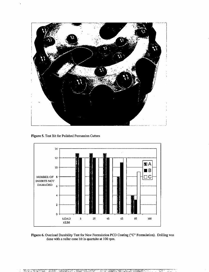
Figure 5. Test Bit for Polished Percussion Cutters
LOAD 5 25 45 65 85 100
KLBs
Figure 6. Overload Durability Test for New Formulation PCD Coating (“C” Formulation). Drilling wasdone with a roller cone bit in quartziteat 100 rpm.
0.90
0.80
❑0.70
A- 0.60- A mGS.(3.504 ~
w
v n
■ “A
+ +’”c”
1 0“40 ■ +A Unpolished “A
P.1 ().30
+
0.20-
0.10
0.00 -i Io 5 10 15 20
Blast Time (rein)
Figure 7. Polish Durability Test for New Formulation PCD Coating (“C” Formulation).