phase 1 expectations - university of delaware
TRANSCRIPT

Agenda-Day 2
• Projections
• Standard Views
• Dimensioning Practices
• AutoCAD Tips for Lab

Engineering Drawing
• Definition:
• Binding legal document that disclosed graphically and in text the form and function of an object.
• Legally binding if created or approved (i.e. stamped) by a professional engineer.

Representing 3D Objects

Projections
• Two basic types
• Perspective
• Parallel
• The objective of technical graphics is not necessarily to present what the eye can see . . .

Perspective Projections
• It essentially what the eye can see
• Common in artistic graphics
• Not as common in technical graphics
• Requires the eye to be a an infinite distance to mitigate distortion
• Exception: virtual environments

Parallel Projections
• Parallel lines of sight
• Define a projection plane• Between the viewer
and object
• Less realistic but much better in terms of accurately representing the features of an object

Parallel vs. Perspective . . .

Types of Parallel Projections
• Oblique-projection direction not orthogonal to viewing plane
• Orthographic - projection plane orthogonal to viewing plane
• Axonometric
• Isometric – shows each direction equally
• Projection plane intersects each coordinate axis at the same distance from the origin
• Multiviews
• Three 2D views

Orthographic vs. Oblique Projections

Axonometric Projections
Isometric Trimetric

30 deg Isometric
1/2 Isometric
Military Isometric
Types ofIsometric

Multiviews for Representing 3D Objects

Movie!
http://highered.mcgraw-hill.com/sites/0073136069/student_view0/chapter5/animations.html#

Standard Multiview Orientation
• Right Side, Top, Front
• Front is the central view
• Top can also be the standard view

Representing 3D Objects with Multiviews
• Number of possible views?
• Answer = 2
• Referred to First and Third Angle Views

First vs. Third Angle Projections

Resulting Standard Views
Front Right

Drafting Practices
• When to use Diameter vs. Radius.
• Over-dimensioning.
• Implied geometry.

Diameter vs. Radius
• Use diameters to dimension holes
• Use radius dimensions for features that have a constant radius but are not a complete hole.

D vs. R
D1.000
R2.0

Dimensioning the Same Feature Twice
O 0.500
O 0.5002.000
0.750
1.250
Default tolerance +/- 0.005
Bad PracticeWrong
(Two different interpretations)

Tolerance Stacking . . .
2.000
0.750
1.250
Default tolerance +/- 0.005
(1.995 to2.005)
(1.990 to2.010)

Implied FeaturesNot typically dimensioned
• Perpendicularness
• Parallelism
• Some symmetric features
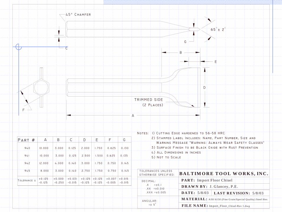
FIL E N A M E : Im port_Floor_C hisel-R ev 1.dw g
L A ST R E V ISIO N : 5 /8/03
B A L T IM O R E T O O L W O R K S, IN C .
PA R T : Im port F loor C hisel
D R A W N B Y : J. G lancey, P .E .
D A T E : 5 /8/03
M A T E R IA L : A ISI 6150 (Fine G rain/Special Q uality) S teel H ex

DimensioningOther Rules of Thumb
• Use font sizes that can be read.
• Try not to place dimensions or leader lines on the part.
• Use comments and notes whenever possible to minimize the number of dimensions required.
• Keep dimensions within the drawing boundary.

On-Line Assignment
• Chapters 1 to 6
• Take the Quiz one time only
• True-False or Multiple Choice (you choose)
• No Homework this week

Lab 2
• Directions and Example available on the Schedule Page
• Tips to Cover:
• Status Bar
• Drawing Layers
• Text Style Managers