ph006-o'driscoll01 10/13/99 5:49 pm page 1 1 overview of...
TRANSCRIPT

1 Overview of Digital TV
In this chapter…
• Terminology 2
• What is Digital Television? 3
• International Standard Bodies and Agreements 5
• Building Blocks of a Digital TV System 11
• Summary 23
1
PH006-O'Driscoll01 10/13/99 5:49 PM Page 1

The tremendous potential of digital television is attracting interest from telecom-munications providers, computer manufacturers, network providers, consumer elec-tronic companies, and broadcasters around the world. Pay Per View, high speedInternet access, video on demand, cable telephony, and e-commerce represent a por-tion of the new money spinning ventures in which industry firms are investing increas-ing amounts of dollars and resources. This chapter acts as a foundation block for thetechnology discussions that follow in later chapters. Here, we introduce the basic con-cepts and benefits of digital television. Then we introduce the various internationalstandard bodies that are involved in establishing sets of technical specifications forimplementing digital TV systems throughout the world. Finally, this chapter providesyou with some detailed information about how the components of the digital broad-casting environment work together.
TERMINOLOGY . . . . . . . . . . . . . . . . . . . . . . . . . . . . .
Before entering a detailed discussion about digital television systems, it is importantthat you understand a number of industry-specific terms. Here’s a short list of the mostimportant ones.
Head-end • An industry term that is used to describe a TV operator’s main oper-ations center.
Set-top box • A set-top box may be defined as a consumer electronics deviceused to decode and tune digital signals and convert them to a format that is understoodby your television.
MHz • MHz is an abbreviation for megahertz. One MHz represents a millioncycles per second. The speed of a processor in a digital set-top box (defined below) ismeasured in MHz.
Bandwidth • If you have ever waited for a page to download into your PC on aSaturday evening, then you’re already familiar with the concept of bandwidth. Thinkof bandwidth as a pipe that carries information. The less bandwidth you have, thelonger the time it will take to download a Web page onto your PC.
Return path • Many of the digital TV services on offer require some form ofinteraction between the subscriber and either the program provider or the networkoperator. This interaction may consist of transmitting a couple of user commands butcan be as extensive as the communications required by a telecommunications link tothe Internet. The term “return path” is used to describe the physical channel that facil-itates this two-way interaction.
Protocol • A protocol is a formal description of the messages that need to beexchanged and the rules that need to be followed for two or more systems to exchangeinformation.
2 1 • Overview of Digital TV
PH006-O'Driscoll01 10/13/99 5:49 PM Page 2

Network service provider • Many of the cable, microwave multipoint distribu-tion services (MMDS), terrestrial, satellite, and broadcasting companies are beginningto move into the telecommunications sector to offer a variety of services that have notbeen associated with their traditional TV-based offerings. Consequently, in this bookwe sometimes refer to this group of companies as service providers or network serviceproviders. A network service provider will not only manage the network infrastruc-ture, but will also control the various services that run over its high-speed networks.
WHAT IS DIGITAL TELEVISION? . . . . . . . . . . . . . . . . .
Digital television, commonly known as digital TV, is a completely new way of broad-casting and is the future of television. It is a medium that requires new thinking andnew revenue-generating business models. Digital TV is the successor to analog TVand eventually all broadcasting will be done in this way.
Around the globe, cable, satellite, and wireless operators are moving to a digitalenvironment. Affiliates of the four major networks in the United States—ABC, NBC,CBS, and Fox were slated to begin digital broadcasts by November 1999. By 2006, theFederal Communications Commission (FCC) in the U.S. has mandated that no moreanalog television signals be broadcast. In Europe, the digital TV train is also rolling outof the station, with broadcasters in France, Ireland, Spain, Germany, Holland, and theU.K. planned to launch digital technologies in 1999. Most industry analysts are pre-dicting that the transition to digital TV will be an evolution rather than a revolution,changing the way of life for hundreds of millions of families around the world.
Companies are acknowledging that the convergence between personal comput-ers, TV sets, and the Internet has already begun and are positioning themselves tomaximize revenue from this new computing paradigm.
For consumers, the digital age will improve their viewing experience throughcinema-quality pictures, CD-quality sound, hundreds of new channels, the power toswitch camera angles, and improved access to a range of exciting new entertainmentservices. Digital TV also gives subscribers the opportunity to enjoy more program-ming through cinema-style wide screen TVs. Gone are the days of choosing betweena small range of channels. Television will become more fun and powerful to use, yetat the same time simpler and friendlier.
For the broadcaster, a move to a digital environment decreases the bandwidthutilization per channel, facilitates the offering of Internet applications to their sub-scribers, and opens a new era of business opportunities.
The new digital technologies will allow cable companies, satellite providers, andwireless broadcasters to offer a variety of powerful revenue-generating services,including:
Terminology 3
PH006-O'Driscoll01 10/13/99 5:49 PM Page 3

• Internet access at blazing speeds;
• multi-user network games;
• video on demand;
• streaming video and audio;
• home banking services;
• e-commerce applications;
• PC software upgrades;
• Broadcasting rich multimedia content; and
• electronic newspapers.
Digital television also opens up a new world of opportunities for companies whowant to develop content and applications for the new paradigm. This includes the cre-ative communities within the television and film industry, Internet content providers,and software development houses, as well as new companies that will be createdaround this new industry.
To fully understand digital TV, we need to look at its origin and how variouscompression and transmission technologies were used to revolutionize the televisionexperience. For the past 50 years, broadcasters have been using analog signals as ameans of transmitting TV to the mass market. During this period, we experienced thetransition from the black-and-white sets to color TV sets. The migration requiredviewers to purchase new TV sets and broadcasters had to acquire new transmitters,posts and production equipment.
The switch from black-and-white to color had palpable benefits for everyone.Today, the industry is going through a profound and amazing transition: migratingfrom conventional TV to a new era of digital technology. Television operators areupgrading their existing networks and deploying advanced digital platforms to open anew world of opportunities for consumers, content providers, and entrepreneurs.
First, digital TV offers high speed data transfer rates, which make the deliveryof rich multimedia content a reality. Second, many cable, terrestrial, and satellite com-panies are establishing themselves as Internet service providers, which will enable TVviewers to browse the Internet on their TV sets.
Finally, the new medium will allow viewers from the comfort of their homes touse a simple remote control to electronically purchase goods and services offered byvarious content providers. Digital TV uses the same language as computers—a longstream of binary digits, each of which is either 0 or 1. With digital television, the sig-nal is compressed and only the updated data is transmitted. As a result, it is possibleto squeeze six or eight channels into a frequency range that was previously occupiedby only one analog TV channel.
The digital TV cycle begins by recording a particular event or program with dig-ital equipment and is relayed to a redistribution center. In most cases, the redistribu-
4 1 • Overview of Digital TV
PH006-O'Driscoll01 10/13/99 5:49 PM Page 4

tion center will be a cable, satellite, MMDS, or terrestrial operator. From here, theoperators use specific transmission techniques to broadcast the new digital signal tosubscribers on their network.
INTERNATIONAL STANDARD BODIES ANDAGREEMENTS . . . . . . . . . . . . . . . . . . . . . . . . . . . . . .
Making digital television a reality requires the cooperation of a variety of industriesand companies, along with the development of many new standards. A wide variety ofinternational organizations have contributed to the standardization of digital TV overthe past couple of years. Most standards organizations create formal standards byusing specific processes: organizing ideas, discussing the approach, developing draftstandards, voting on all or certain aspects of the standards, and then formally releas-ing the completed standard to the general public. Some of the best-known interna-tional organizations that contribute to standardizing of digital television include:
• the European Telecommunications Standards Institute (ETSI);
• Digital Video Broadcasting (DVB);
• the Advanced Television Systems Committee (ATSC);
• the Digital Audio Visual Council (DAVIC);
• the European Cable Communications Association (ECCA);
• CableLabs;
• the W3 consortium; and
• the Federal Communications Commission (FCC).
Their contribution to the standardization process is explained and detailed in thefollowing sections.
European Telecommunications StandardsInstitute (ETSI)
ETSI is a nonprofit organization whose mission is to determine and produce a widerange of telecommunication standards. It is an open forum that unites approximately647 members from countries all over the globe, representing administrations, serviceproviders, manufacturers, and end-users. Any European organization proving an inter-est in promoting European telecommunications standards has the right to representthat interest in ETSI and thus to directly influence the standards-making process. ETSIconsists of a General Assembly, a Board, a Technical Organization, and a Secretariat.The Technical Organization produces and approves technical standards. It encom-
What is Digital Television? 5
PH006-O'Driscoll01 10/13/99 5:49 PM Page 5

passes ETSI projects, technical committees, and special committees. More than 3,500experts are at present working for ETSI in over 200 groups. (Additional informationabout ETSI is available from their web site at http://www.etsi.org/).
Digital Video Broadcasting (DVB)
The DVB project was conceived in 1991 and was formally inaugurated in 1993 withapproximately 80 members. Today, the DVB project has made huge advancements andboasts a membership of over 230 organizations in more than 30 countries worldwide.
Members of the group include electronic manufacturers, network operators,broadcasters, software companies, and various regulatory bodies.
The DVB project has been a big success and has generated various standards fordelivering digital TV to people throughout Europe, Asia, Australia, and North America.
The work of the DVB project has resulted in a comprehensive list of technicaland nontechnical documents that describe solutions for implementing digital televi-sion in a variety of different environments.
The international standards and solutions developed by DVB over the past fewyears can be classified and summarized as follows:
1. DVB-S—An international standard for transmitting digital televisionusing satellites.
2. DVB-C—An international standard for transmitting digital televisionusing digital cable systems.
3. DVB-T—An international standard for transmitting digital television in aterrestrial environment.
4. DVB-MC/S—An international standard for transmitting digital televisionusing microwave multipoint video distribution systems.
5. DVB-SI—An international standard that defines the data structures thataccompany a digital television signal.
6. DVB-CA—An international standard that defines digital television secu-rity standards.
7. DVB-CI—An international standard that defines a common interface tothe digital TV security system.
8. DVB-I—An international standard for deploying interactive TV.
9. DVB-Data—An international standard designed to allow operators todeliver software downloads and high speed data services to their customers.
10. Interfaces—An international standard that defines digital TV interfaces tohigh speed backbone networks.
6 1 • Overview of Digital TV
PH006-O'Driscoll01 10/13/99 5:49 PM Page 6
Copies of these standards are available for download on ETSI’s web site.
DVB-compliant digital equipment is widely available and is easily identified bythe DVB logo illustrated in Figure 1.1. The DVB has had its greatest success inEurope, however the standard has implementations in North and South America,Africa, Asia, and Australia. For additional information about DVB, visit their web siteat http://www.dvb.org/.
Advanced Television Systems Committee(ATSC)
The ATSC committee was formed to establish a set of technical standards for broad-casting standard and High Definition Television (HDTV). Pictures based on this stan-dard can have 3 to 5 times the sharpness of today’s analog broadcasts.
The committee is composed of 136 member organizations, standard bodies, ITcorporations, educational institutions, and electronic manufacturers. It has been for-mally adopted in the United States, where an aggressive implementation of digital TVhas already begun. In addition to the U.S., Canada, South Korea, Taiwan, andArgentina have also adopted the ATSC digital TV standard for terrestrial broadcasts.A sample of the ATSC standards are outlined in Table 1.1.
International Standard Bodies and Agreements 7
The Standard for theDigital World
Figure 1.1DVB Logo
PH006-O'Driscoll01 10/13/99 5:49 PM Page 7

Table 1.1 ATSC Standard Documents
Document Standard Description Brief Overview Web Address ofNumber Detailed Document
8 1 • Overview of Digital TV
A/52 ATSC Digital AudioCompression
Specifies coded represen-tation of audio informationand the decoding process,as well as information onthe encoding process
www.atsc.org/Standards/A52/
A/53 ATSC DigitalTelevision Standard
Specifications and charac-teristics for an advancedTV (ATV) system
www.atsc.org/Standards/A53/
A/54 ATSC Guide Description of ATV system www.atsc.org/Standards/A54/
A/64 Transmission measure-ment and compliancefor digital television
Description of measure-ment and ATSC compli-ance system
www.atsc.org/Standards/A64/
This table only displays a snapshot of the ATSC standards. To review the com-plete listings of ATSC standards, we recommend you visit the ATSC Web page athttp://www.atsc.org/Standards/stan_rps.html for a more detailed listing.
For the latest information and updates about ATSC, visit their web site athttp://www.atsc.org/.
Digital Audio Visual Council (DAVIC)
The organization was formed in 1994 with the aim of defining standards for the end-to-end transfer of digital audio, video, and Internet-based content.
DAVIC is a nonprofit standards organization currently located in Switzerland. Theorganization currently has a membership of over 180 companies from 25 countries aroundthe globe, representing companies and individuals from all sectors of the audio-visualindustry. DAVIC members meet on a regular basis to define specifications and use theirweb site (www.davic.org) to collaborate and implement various international projects.
European Cable CommunicationsAssociation (ECCA)
ECCA is the European Association of cable operators. The main goal of theAssociation is to foster cooperation between operators, and to promote their interests
PH006-O'Driscoll01 10/13/99 5:49 PM Page 8

at a European level. ECCA gathers European cable operators, consisting of more than40 million subscribers. The first informal cooperation between European cable opera-tors started in 1949. As these informal meetings became more frequent, a formal struc-ture for European cooperation was required and on September 2, 1955, the AllianceInternationale de la Distribution par câble (AID) was set up by representatives ofSwitzerland, Belgium, and The Netherlands. In 1993, AID was renamed the EuropeanCable Communications Association, thus stressing the communication role of itsmembers as well as its European goals.
ECCA now has 29 members in 17 countries. It also has 5 associate members incentral and eastern Europe. ECCA has considerably contributed to European policiesrelated to cable on the regulatory as well as on the technical standards field.
On the regulatory, ECCA has done a lot of work on areas such as digital TV,copyright, must-carry, and open-access issues. In addition to these projects, ECCAmembers have also compiled the following technical specifications.
Eurobox
On initiative of the ECCA organization, a common specification for cable set-topboxes following DVB standards was agreed upon by a large number of cable opera-tors in Europe (the Eurobox platform).
The Eurobox platform was set up in 1997, and has more than 5.5 million sub-scribers. A more detailed description of the Eurobox is available in Chapter 5 of thisbook.
Euromodem
A collective resolution to develop a global standard for high speed cable modems wassigned at the ECCA Cable Forum in November 1998. The standard fully complieswith European standards and with several DVB specifications. The ECCA group hasconsidered two different types of modems: class A and class B. Class A modems arecapable of transmitting data at very high speeds in a downstream direction (maximumof 50.8 Mbits/sec) and 3 Mbits/sec in the upstream direction. They are capable ofaccessing the Internet at high speeds and support a number of security technologies.Class B is the second type of modem considered by the group. It extends the func-tionality of class A devices through the support of time critical services such as videoconferencing and telephony. At the time of going to press, a number of electronic man-ufacturing companies were invited to submit plans to manufacture modems compliantwith the Euromodem standard.
International Standard Bodies and Agreements 9
PH006-O'Driscoll01 10/13/99 5:49 PM Page 9

Cable telephony
On the basis of the full liberalization of the telecommunications sector in Europe,cable companies, satellite providers, and terrestrial broadcasters in different countriesare planning to become competitors to the local telephony companies. Therefore, theirnetworks are being or have been upgraded to broadband telecommunications net-works, which are able to provide all kinds of services from telephony and localInternet access to high speed broadband connections. ECCA is also actively workingin this area. For additional information about ECCA, visit their web site athttp://www.ecca.be/.
CableLabs
Cable Television Laboratories, Incorporated (CableLabs), was originally establishedin May 1988 as a research and development consortium of cable television systemoperators. To qualify as a member of CableLabs, a company needs to be a cable tele-vision system operator. CableLabs currently represents more than 85 percent of thecable subscribers in the United States, 70 percent of the subscribers in Canada, and 10percent of the subscribers in Mexico. CableLabs plans, funds, and implements a num-ber of research and projects that help cable companies take advantage of future oppor-tunities in the areas of digital TV, telephony, and high speed Internet. For additionalinformation about CableLabs, visit their web site at http://www.cablelabs.com/.
W3 Consortium (W3C)
The W3 Consortium (W3C) was originally founded in 1994 to lead the World WideWeb to its full potential by developing common protocols that promote its evolutionand ensure its interoperability. The organization is an international consortium, joint-ly hosted by the Massachusetts Institute of Technology in the U.S; an organization inEurope called the Institut National de Recherche en Informatique et en Automatique,and Keio University in Japan.
The consortium provides a range of services, including: a repository of infor-mation about the World Wide Web for developers and users; reference code imple-mentations to embody and promote standards; and various prototype and sampleapplications to demonstrate use of new technology. For detailed information about theW3C, visit their web site at http://www.w3c.org/.
Federal Communications Commission (FCC)
The Federal Communications Commission (FCC) is an independent United States gov-ernment agency, directly responsible to Congress. The FCC was established by the
10 1 • Overview of Digital TV
PH006-O'Driscoll01 10/13/99 5:49 PM Page 10

Communications Act of 1934 and is charged with regulating interstate and internation-al communications by radio, television, wire, satellite, and cable. The FCC’s jurisdic-tion covers the 50 states, the District of Columbia, and U.S. possessions. There are sixoperating bureaus. The bureaus are: Mass Media, Cable Services, Common Carrier,Compliance and Information, Wireless Telecommunications, and International. Thesebureaus are responsible for developing and implementing regulatory programs, pro-cessing applications for licenses or other filings, analyzing complaints, conductinginvestigations, and taking part in FCC hearings.
The Cable Services Bureau was established in 1993 to administer the cableTelevision Consumer Protection and Competition Act of 1992. The Bureau enforcesregulations designed to ensure that cable rates are reasonable under the law. It is alsoresponsible for regulations concerning “must carry,” retransmission consent, customerservices, technical standards, home wiring, consumer electronics, equipment compat-ibility, indecency, leased access, and program access provisions. The Bureau also ana-lyzes trends and developments in the industry to assess the effectiveness of the cableregulations. For additional information about the FCC, visit their web site athttp://www.fcc.gov/.
BUILDING BLOCKS OF A DIGITAL TV SYSTEM . . . . . . .
A TV operator normally receives content from a variety of sources, including local video,cable, and satellite channels. The content needs to be prepared for transmission to the cus-tomer’s home by passing the signal through a digital broadcasting system. The diagramin Figure 1.2 depicts the basic building blocks of a digital broadcasting system.
Note that the components shown in this diagram are logical units and do not nec-essarily correspond to the number of physical devices that are deployed in a total end-to-end digital solution. The role of each component shown in Figure 1.2 is briefly out-lined in the following categories.
Compression and Encoding
Central to a digital video-broadcasting network is the compression system, whose jobis to deliver high quality video and audio to consumers using a small amount of net-work bandwidth. The main goal of any compression system is to minimize the storagecapacity of information. This is particularly useful for service providers who want to“squeeze” many digital channels into a digital stream.
A compression system consists of encoders and multiplexers. Encoders aredevices used to digitize, compress, and scramble a range of audio, video, and datachannels. Digital encoders allow TV operators to broadcast several high quality video
International Standard Bodies and Agreements 11
PH006-O'Driscoll01 10/13/99 5:49 PM Page 11

12 1 • Overview of Digital TV
Sat
ellit
e
Sat
ellit
e
MM
DS
or
terr
estr
ial t
ow
er
Mo
nit
or
Ser
ver
Loca
l Dig
ital
Ch
ann
els
SM
SS
AS
Dat
a
Receiv
ing
Dig
ital S
ign
als
Netw
ork
Man
ag
em
en
t
Co
nd
itio
nal A
ccess S
yste
m
Co
mp
ressio
n a
nd
En
co
din
g
QA
M
QP
SK
CO
FD
M
Mo
du
lati
on
Off
Air
Cab
le T
VN
etw
ork
Fig
ure
1.2
Sim
plifi
ed b
lock
dia
gra
m d
epic
ting
th
e b
asic
bu
ildin
g b
lock
s o
f a
dig
ital b
road
cast
ing
sys
tem
PH006-O'Driscoll01 10/13/99 5:49 PM Page 12

programs over the same bandwidth that was formerly used to broadcast just one ana-log video program.
Once the signal is encoded and compressed, an MPEG-2 stream is transmittedto the multiplexer (MPEG-2 is an acronym for Moving Pictures Experts Group). Thisgroup has defined a range of compression standards and file formats, including theMPEG-2 video animation system. MPEG-2 is generally accepted in 190 countriesworldwide as the standard for digital video compression. There are two major MPEGstandards available on the market today: MPEG-1 and MPEG-2.
The MPEG-1 file format is normally used by interactive TV developers to cre-ate TV “stills” and has a quality level slightly less than conventional video cassetterecorders. The MPEG-2 file format is used in a digital broadcasting environment andfeatures CD-quality audio complemented with a high screen resolution. Once the sig-nal has been compressed into MPEG-2 format, the multiplexer combines the outputsfrom the various encoders together with the security and program information anddata into a single digital stream.
Modulation
Once the digital signal has been processed by the multiplexer, it is now time to amal-gamate the video, audio, and data with the carrier signal in a process called modula-tion. The unmodulated digital signal outputted from the multiplexer has only two pos-sible states, either a “zero” or a “one.” By passing the signal through a modulation pro-cess, a number of states are added, which increases the data transfer rate. The modu-lation technique used by TV operators will depend on the geography of the franchisearea and the overall network architecture.
The three major types of digital modulation are Quadrature AmplitudeModulation, Quadrature Phase Shift Keying, and Coded Orthogonal FrequencyDivision Multiplexing.
Quadrature Amplitude Modulation (QAM)
QAM is a relatively simple technique for carrying digital information from the TVoperator’s broadcast center to the customer. This form of modulation modifies theamplitude and phase of a signal to transmit the MPEG-2 transport stream. QAM is thepreferred modulation scheme for cable companies because it can achieve transfer ratesup to 40 Mbits/sec.
Building Blocks of a Digital TV System 13
PH006-O'Driscoll01 10/13/99 5:49 PM Page 13
Quadrature Phase Shift Keying (QPSK)
QPSK is more immune then QAM to electromagnetic noise and is normally used in asatellite environment or on the return path for a cable television network. QPSK workson the principle of shifting the digital signal so that it is out of phase with the incom-ing signal. QPSK will improve the robustness of a network, however, this modulationscheme is only capable of transmitting data at 10 Mbits/sec.
Coded Orthogonal Frequency Division Multiplexing(COFDM)
COFDM operates extremely well in heavily built-up areas where digital transmissionsbecome distorted by obstacles such as buildings, bridges, and hills. COFDM is differ-ent to QAM because it uses multiple signal carriers to transfer information from onenode on the network to another. At the moment, COFDM may be implemented witheither 2,000 (2K) or 8,000 (8K) carrier signals. European terrestrial and MMDS oper-ators mainly use the COFDM modulation scheme. In contrast, COFDM has not beendeployed in the United States because the ATSC (Advanced Television SystemsCommittee) has defined a digital terrestrial system that meets the needs of a less-rugged geographical terrain.
Conditional Access System
Broadcast and TV operators are now interacting with their viewers on many levels, offer-ing them a greater program choice than ever before. Additionally, the deployment of asecurity system or conditional access (CA), as it is commonly called, provides them withunprecedented control over what they watch and when. A CA system is best describedas a virtual gateway that allows viewers to access a new world of digital services.
The main goal of any CA system is to control subscribers’ access to digital TVpay services and secure the operators revenue streams. Consequently, only customersthat have a valid contract with the network operator can access a particular service.Using today’s CA systems, network operators are able to directly target programming,advertisements, and promotions to subscribers by geographical area, market segment,or according to personal preferences. The CA system is therefore a vital aspect of thedigital TV business. In technical terms, the key elements of the CA system are illus-trated in Figure 1.3.
Restricting access to a particular service is accomplished by using a techniquecalled cryptography. It protects the digital service by transforming the signal into anunreadable format. The transformation process is known as “encryption” in a digitalenvironment and “scrambling” in an analog domain. Once the signal is encrypted, itcan only be decrypted by means of a digital set-top box. Decryption is the process
14 1 • Overview of Digital TV
PH006-O'Driscoll01 10/13/99 5:49 PM Page 14

Building Blocks of a Digital TV System 15
Req
ues
ts
EM
M a
nd
EC
MM
essa
ges
Fin
anci
al T
ran
sact
ion
s
En
cryp
ted
Dig
ital T
VS
ign
al
Su
bscri
ber
Au
tho
rizati
on
Syste
m
En
cry
pti
on
Hard
ware
Su
bscri
ber
Man
ag
em
en
tS
yste
m
Key a
nd
Messag
eG
en
era
tor
TV
Sig
nal
Au
tho
rizati
on
s
Mu
ltip
lex
Cu
sto
mers
TV
Bro
ad
ban
d
Netw
ork
Fig
ure
1.3
Bas
ic p
rin
cip
le o
f an
en
d-to
-en
d c
on
diti
on
al a
cces
s sy
stem
PH006-O'Driscoll01 10/13/99 5:49 PM Page 15

used to convert the message back to its original format. This is carried out using adecryption key. A key is best described as a secret value, consisting of a random stringof bits, which is used by a computer in conjunction with mathematical formulas calledalgorithms to encrypt and decrypt information.
The box incorporates the necessary hardware and software subsystems to receiveand decrypt the signal. These components are comprised of a de-encryption chip, asecure processor, and some appropriate hardware drivers. The de-encryption chip isresponsible for holding the algorithm section of the CA. The secure processor caneither be soldered onto the set-top box’s printed circuit board or else attached to asmart card. Smart cards are plastic cards that look like credit cards. This processorcontains the necessary keys needed to decrypt the various services. Chapter 11 dis-cusses the cryptography aspects of smart card security in more detail.
A given subscriber may decrypt and access the digital signal only if the subscriberhas purchased the relevant entitlement. As an example, the entitlement may be providedin the form of an electronic smart card that is plugged into the set-top box. Alternatively,in a pay-per-view scenario, the entitlement may be delivered electronically by entitle-ment management messages (EMMs) and entitlement control messages (ECMs) withinthe broadcast stream. An EMM is used to carry authorization details and are subscriber-specific. Consequently, the number of EMMs that need to be sent over the broadbandnetwork is proportional to the number of set-tops on the network. In addition to sendingEMMs to specific customers, operators can also broadcast EMMs to groups of sub-scribers in different geographical areas. ECMs, on the other hand, carry program- andservice-specific information, including control words that are used by the smart card todecrypt the relevant program. However, if a subscriber is not entitled to watch the pro-gram, then a signal is sent to the set-top box to indicate that this program has not beenauthorized for de-encryption. ECMs and EMMs are generated and broadcasted at the TVoperations center using specialized hardware devices. They are then transmitted to theviewer’s smart card. The card will check access rights and descramble the requested dig-ital services. It is possible to change the value of an ECM every 10 seconds in order tomaximize security on a digital network. A typical smart card is capable of storing up toa hundred entitlement messages, which means that each subscriber on the network iscapable of ordering 100 pay-TV events at any one time.
In addition to encrypting digital services, the CA also interfaces with the fol-lowing subsystems:
Subscriber Management System (SMS)
To exploit the commercial potential of digital broadcasting, TV operators need tointerface their technical systems with a subscriber management system (SMS). TheSMS provides the support required to accurately manage the digital TV businessmodel. It handles the customer database and sends requests to the subscriber autho-
16 1 • Overview of Digital TV
PH006-O'Driscoll01 10/13/99 5:49 PM Page 16

rization system (SAS)—the technical management part of the CA system. Functionstypically provided by an SMS software application system include:
• register, modify, and cancel subscriber records;
• targeted marketing campaigns;
• inventory management of set-tops and smart cards;
• customer experience tracking;
• cross-selling of services;
• interfacing with banks and credit card companies;
• fault management;
• multilingual and multicurrency capability;
• bill preparation and formatting;
• presentation of bills in electronic formats; and
• accounting and auditing facilities.
Many of the software solutions currently available in the marketplace are capa-ble of supporting the increasing variety of interactive services offered to subscribers.The main goal of any SMS system is to ensure that subscribers view exactly what theypay for.
Subscriber Authorization System (SAS)
The main task of the SAS is to translate the requests coming from the SMS intoEMMs. These authorization messages are then sent via the digital multiplex to thesmart card, which is located in the set-top box. They are sent to customers on a regu-lar interval (for example, every month) to renew subscription rights on the smart card.In the case of Pay Per View (PPV) applications, the SAS sends a certain amount ofelectronic tokens to the smart card that will allow customers to purchase a variety ofPPV events. The SAS contains database(s) that are capable of storing the followingitems of information:
• pay TV product information,
• data to support the electronic TV guide,
• identification numbers of smart cards,
• customer profiles, and
• scheduling data.
Additionally, SAS security can be enhanced by periodically changing the autho-rization keys broadcasted to the subscriber base. Some well-known CA systems include:
Building Blocks of a Digital TV System 17
PH006-O'Driscoll01 10/13/99 5:49 PM Page 17

• CryptoWorks from Philips,
• Viaccess from France Telecom,
• Nagra from NagraVision,
• MediaGuard from Canal+ Technologies,
• VideoGuard from NDS,
• DigiCipher from General Instruments, and
• Iredeto from MindPort.
Network Transmission Technologies
Several different technologies have been deployed to bring broadband entertainmentservices from a central point to customers on a digital TV network. The different dis-tribution systems (or mix of systems) adopted to broadcast digital TV services incountries around the world has largely been a function of each market’s unique char-acteristics, including elements such as topography, population density, existing broad-cast infrastructure, as well as social and cultural factors.
The most popular of these technologies are detailed in the following subsections.
Digital Via Hybrid Fiber-Coax (HFC)
Hybrid fiber-coax (HFC) technology refers to any network configuration of fiber-opticand coaxial cable that may be used to redistribute a variety of broadband entertainmentservices. These broadband services include telephony, interactive multimedia, highspeed Internet access, video-on-demand, and distance learning. The types of servicesprovided to consumers will vary between cable companies.
Many of the major cable television companies in the United States, Europe,Latin America, and Southeast Asia are already using it. Networks built using HFCtechnology have many characteristics that make it ideal for handling the next genera-tion of communication services. First and foremost, HFC networks can simultaneous-ly transmit broadband analog and digital services. This is extremely important for net-work operators who are rolling out digital TV to their subscribers on a phased basis.Additionally, HFC meets the expandable capacity and reliability requirements of anew digital TV system. HFC’s expandable capacity allows network operators to addservices incrementally without major changes to the overall plant infrastructure. HFCis essentially a “pay as you go” architecture that matches infrastructure investmentwith new revenue streams, operational savings, and reliability enhancements. TheHFC network architecture is comprised of fiber transmitters, optical nodes, fiber andcoaxial cables, and distribution hubs. An end-to-end HFC network is illustrated inFigure 1.4.
18 1 • Overview of Digital TV
PH006-O'Driscoll01 10/13/99 5:49 PM Page 18
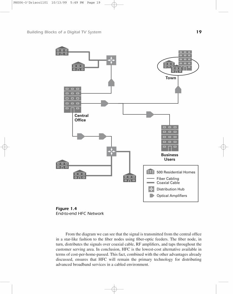
From the diagram we can see that the signal is transmitted from the central officein a star-like fashion to the fiber nodes using fiber-optic feeders. The fiber node, inturn, distributes the signals over coaxial cable, RF amplifiers, and taps throughout thecustomer serving area. In conclusion, HFC is the lowest-cost alternative available interms of cost-per-home-passed. This fact, combined with the other advantages alreadydiscussed, ensures that HFC will remain the primary technology for distributingadvanced broadband services in a cabled environment.
Building Blocks of a Digital TV System 19
500 Residential Homes
Fiber CablingCoaxial Cable
Distribution Hub
Optical Amplifiers
BusinessUsers
CentralOffice
Town
Figure 1.4End-to-end HFC Network
PH006-O'Driscoll01 10/13/99 5:49 PM Page 19
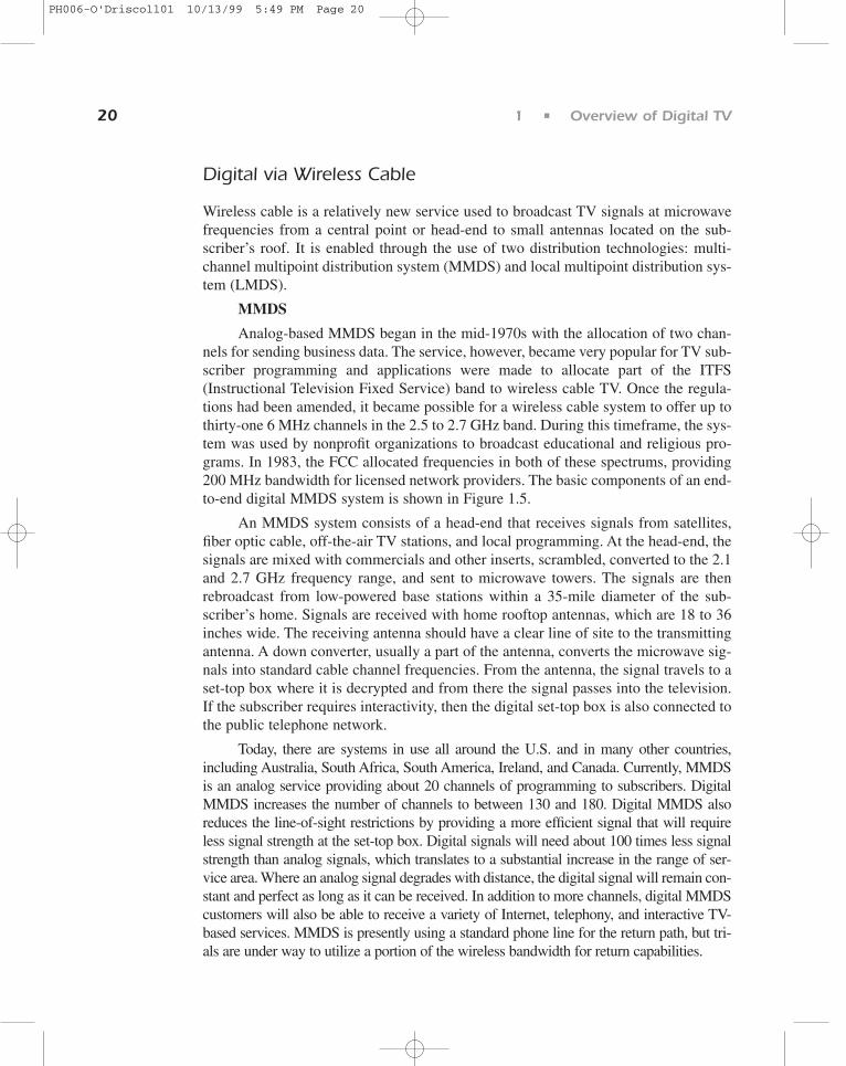
Digital via Wireless Cable
Wireless cable is a relatively new service used to broadcast TV signals at microwavefrequencies from a central point or head-end to small antennas located on the sub-scriber’s roof. It is enabled through the use of two distribution technologies: multi-channel multipoint distribution system (MMDS) and local multipoint distribution sys-tem (LMDS).
MMDS
Analog-based MMDS began in the mid-1970s with the allocation of two chan-nels for sending business data. The service, however, became very popular for TV sub-scriber programming and applications were made to allocate part of the ITFS(Instructional Television Fixed Service) band to wireless cable TV. Once the regula-tions had been amended, it became possible for a wireless cable system to offer up tothirty-one 6 MHz channels in the 2.5 to 2.7 GHz band. During this timeframe, the sys-tem was used by nonprofit organizations to broadcast educational and religious pro-grams. In 1983, the FCC allocated frequencies in both of these spectrums, providing200 MHz bandwidth for licensed network providers. The basic components of an end-to-end digital MMDS system is shown in Figure 1.5.
An MMDS system consists of a head-end that receives signals from satellites,fiber optic cable, off-the-air TV stations, and local programming. At the head-end, thesignals are mixed with commercials and other inserts, scrambled, converted to the 2.1and 2.7 GHz frequency range, and sent to microwave towers. The signals are thenrebroadcast from low-powered base stations within a 35-mile diameter of the sub-scriber’s home. Signals are received with home rooftop antennas, which are 18 to 36inches wide. The receiving antenna should have a clear line of site to the transmittingantenna. A down converter, usually a part of the antenna, converts the microwave sig-nals into standard cable channel frequencies. From the antenna, the signal travels to aset-top box where it is decrypted and from there the signal passes into the television.If the subscriber requires interactivity, then the digital set-top box is also connected tothe public telephone network.
Today, there are systems in use all around the U.S. and in many other countries,including Australia, South Africa, South America, Ireland, and Canada. Currently, MMDSis an analog service providing about 20 channels of programming to subscribers. DigitalMMDS increases the number of channels to between 130 and 180. Digital MMDS alsoreduces the line-of-sight restrictions by providing a more efficient signal that will requireless signal strength at the set-top box. Digital signals will need about 100 times less signalstrength than analog signals, which translates to a substantial increase in the range of ser-vice area. Where an analog signal degrades with distance, the digital signal will remain con-stant and perfect as long as it can be received. In addition to more channels, digital MMDScustomers will also be able to receive a variety of Internet, telephony, and interactive TV-based services. MMDS is presently using a standard phone line for the return path, but tri-als are under way to utilize a portion of the wireless bandwidth for return capabilities.
20 1 • Overview of Digital TV
PH006-O'Driscoll01 10/13/99 5:49 PM Page 20

In Ireland for example, MMDS operators are currently very active in testing anddelivering a diversity of advanced digital TV and Internet services using MMDS net-work transmission techniques to customers across the island. The services on offer tocustomers include:
• high speed access to the Internet;
• private data networks for companies on the island;
• broadcast video and Pay Per View television;
• Plain Old Telephone Service (POTS); and
• fractional and full leased lines
Building Blocks of a Digital TV System 21
Satellite
Local Digital Channels
Receiving Digital Signals
Conditional Access System
Compression and Encoding
Network Management
Modulation
Central Head-End
Off Air
MMDS tower
2.1 and2.7 GHZ
MMDS tower
TelephoneNetwork
Figure 1.5End-to-end digital MMDS solution
PH006-O'Driscoll01 10/13/99 5:49 PM Page 21

Future services discussed by Irish operators include video conferencing anddelivering multimedia training courses to remote parts of the country using advancedMMDS digital technologies. MMDS operators across the world are adopting similarapproaches to their Irish counterparts and are poised to take advantage of the excitingnew digital MMDS broadcasting revolution, allowing the delivery of a variety of ser-vices to their customer bases.
LMDS
LMDS uses microwave frequencies in the 28 GHz frequency range to send andreceive broadband signals, which are suitable for the transmission of video, voice, andmultimedia data. Digital LMDS has been commercially deployed and is used to delivervideo programming from local and cable channels. Additionally, it is also capable ofdelivering a plethora of Internet- and telephony-based services to consumers. The systemarchitecture for LMDS is very similar to the MMDS system. The reception and process-ing of programming and other head-end functions are the same. The signals are thenrebroadcasted from low-powered base stations in a 4–6 mile radius of the subscriber’shome. Signals are then received using six square-inch antennas, which can be mountedeither inside or outside the home. As with the MMDS, the signal travels to the set-top box,decrypted, and formatted for display on the customer’s television. In addition to a highvideo and audio quality, other benefits of LMDS include its bandwidth range of 1 GHzand the availability of a return channel for interactive TV services.
Digital via Terrestrial
Commercially launched in the U.K. in November 1998, terrestrial communications, orDTT as it is commonly called, can also be used to broadcast a range of digital services.
Elements of a terrestrial communications network include:
1. Transmission medium—Services are normally provided via the ultra highfrequency band (UHF). The frequencies in this band range from 300 MHzup to 3 GHz. Standard 8 MHz channels are used and shared with analogtransmissions.
2. Modulation scheme—DTT uses the COFDM modulation scheme. The mainpurpose of COFDM is to make the terrestrial signal immune to multipathreflections. In other words, the signal needs to be robust enough to traversegeographical areas that include mountains, trees, and large buildings.
3. Transmission infrastructure—Uses an existing network of broadcast sta-tions and transmitters.
4. Customer’s premises equipment—With a modern aerial, there should beno need to replace it to receive the DTT service. If the aerial is a very oldone, the viewer would certainly benefit from updating. Additionally, DTT
22 1 • Overview of Digital TV
PH006-O'Driscoll01 10/13/99 5:49 PM Page 22

necessitates the purchase of a new digital set-top box to receive anddecode the digital signal.
Digital via Direct Broadcast Satellite (DBS)
Digital television is also available through direct broadcast satellite (DBS), which canprovide higher bandwidth than terrestrial, MMDS, or cable transmission.
Direct Broadcast Satellite (DBS) is a service whereby you receive subscriptiontelevision from a single high-powered satellite. This satellite is typically located about22,000 miles above the surface of the earth. At the moment, when you subscribe to ananalog service you receive a state-of-the art mini-dish that is maintained and ownedby the local distributor, along with a decoder for your television set that unscramblesthe signals received from the satellite. This year, consumers will be able to receive dig-ital satellite service by installing a new and smaller digital satellite dish and buying anew digital satellite set-top box. Digital via DBS brings consumers more channels tochoose from, new features, and new services.
Network Management
As you can see the broadcasting center is made up of many complex components. Asthese components handle more and more services, network problems must be quicklydetected and resolved. To maximize system uptime and monitor the services deliveredto customers, a network monitoring and control system is installed at the broadcastingcenter. The main goal of such a system is to minimize service interruptions to digitalTV customers. Features of a typical head-end control system include:
• monitoring the availability of devices,
• gathering statistics,
• reporting alarms and problems to support personnel, and
• remote diagnostics.
The systems available at present are vendor-specific and will run on eitherWindows NT or UNIX platforms.
SUMMARY . . . . . . . . . . . . . . . . . . . . . . . . . . . . . . . . .
Digital television brings about many challenges, but with those challenges come a lotof opportunities. Advances in technology over the past few years have meant that the
Building Blocks of a Digital TV System 23
PH006-O'Driscoll01 10/13/99 5:49 PM Page 23

possibility of delivering digital television services to billions of people around theglobe has moved from the realms of fantasy into reality.
Digital TV offers a potential mechanism through which every home, school, busi-ness, and community center in the world could be included in the information society.
It opens up a new world of opportunity for companies to develop and utilize theirexisting network infrastructures. This includes broadcasters; cable and satellite com-panies; the creative community in television and film; Internet content providers; website producers; and new, innovative companies that will form around the future of dig-ital TV. The broadcast of digital TV and multimedia data works well because of theagreements and partnerships forged by a number of organizations around the world. Acomplete digital broadcasting system is comprised of a number of building blocksincluding the compression, encoding, and modulation-system, a CA system for secu-rity purposes; network transmission media to deliver the digital services; and, finally,a network management system to detect and resolve problems.
24 1 • Overview of Digital TV
PH006-O'Driscoll01 10/13/99 5:49 PM Page 24