pflow vertical lifts · 2018-02-21 · contact information . ii contact information...
TRANSCRIPT

PFLOW VERTICAL LIFTS The Nation's Largest Manufacturer of Vertical Lifts
READ THIS MANUAL IN ITS ENTIRETY AND VERIFY JOB SITE DIMENSIONS AGAINST GENERAL
ARRANGEMENT DRAWING BEFORE STARTING THE INSTALLATION
The illustrations in this manual are not to scale or detail and are for reference only.
OWNER'S, INSTALLATION
& MAINTENANCE
MANUAL
SERIES B
PFLOW INDUSTRIES, INC. 6720 North Teutonia Avenue Milwaukee, WI 53209
Phone (414) 352-9000 Fax (414) 352-9002
Email [email protected]
N:\15xxx\15719-0001 022015 REV. D 04/01/16

REV. D 04/01/16

CONTACT INFORMATION
CONTACT INFORMATION i N:\MANUALS\15705-0011.Docx 2016.04.01
PFlow Industries, Inc. 6720 N. Teutonia Avenue
Milwaukee, Wisconsin, 53209 www.pflow.com
Main Office Phone ---------- 414-352-9000
Main Office Fax ---------- 414-352-9002
Product Support Department Fax ---------- 414-247-9834
Phone Extension
Mobil Phone
Field Service Technician Cory Felsinger 220 -
Field Service Technician Eric Key 153 414-510-6946
Field Service Technician Jorge Thompson 223 -
Field Service Technician Kevin Vaile 181 414-915-3732
Senior Technical Advisor Jay Winston 167 414-915-3968
Technical Support Jeff Bittner 105 -
Service Manager Mitch Cain 172 -
Field Support Operations Manager Kevin Sprong 178 414-807-0336
Product Support Manager Pat Herrmann 126 414-745-5813
Electrical Engineering Jonathan Kumbera 111 -
Mechanical Engineering Mike Reilly 184 -
Director of Sales Engineering Brent Bayer 173 -
Documentation PFlow Industries reserves the right to make changes or improvements to the standard VRC model line at any time.
This manual is protected by U.S. Federal Copyright laws© PFlow Industries, Inc. No part of this manual may be duplicated or transcribed in any form without expressed written permission from PFlow Industries, Inc.
System Modifications/Disclaimer Mechanical or electrical modifications performed on the VRC not approved by PFlow Industries, Inc. may also void any warranty and/or service agreements. Please contact the PFlow Sales or Service Department at one of the numbers listed above for assistance with service modifications.
e-mail:
Product Support Department: [email protected]
Sales: [email protected]

CONTACT INFORMATION
ii CONTACT INFORMATION N:\MANUALS\15705-0011.Docx 2016.04.01
Notes

TABLE OF CONTENTS
TABLE OF CONTENTS ............................................................................................................... 1
INTRODUCTION ............................................................................................................................. 3
SAFETY ........................................................................................................................................ 4
EQUIPMENT ARRIVAL AND UNPACKING ............................................................................... 5
Bracing Typical ........................................................................................................................ 5
PRE-INSTALLATION CHECKLIST............................................................................................... 6
Mechanical Installer Responsibilities ...................................................................................... 6
Customer Responsibilities ....................................................................................................... 6
SITE VS. GENERAL ARRANGEMENT ...................................................................................... 7
Comparison Check .................................................................................................................. 7
TOOLS REQUIRED FOR VRC INSTALLATION ....................................................................... 8
INSTALLATION COMPLETION CHECKLIST ............................................................................ 9
INSTALLATION INSTRUCTIONS ............................................................................................. 11
Lifts Shipped Knocked Down (Multiple Sections) Proceed to page 15 ................................ 11
Lifts Shipped in One Piece .................................................................................................... 11
Anchoring & Bracing .............................................................................................................. 12
Adjustments, if needed .......................................................................................................... 13
Start Up .................................................................................................................................. 14
INSTALLATION INSTRUCTIONS ............................................................................................. 15
Lifts Shipped in Pieces .......................................................................................................... 15
Anchoring & Bracing .............................................................................................................. 17
Adjustments, if needed .......................................................................................................... 21
Start Up .................................................................................................................................. 22
ELECTRICAL OVERVIEW SERIES B .................................................................................... 23
QUICK-CONNECT CABLING FOR SERIES B MECHANICAL UNITS .................................. 25
WARRANTY ............................................................................................................................... 27
MAINTENANCE INSTRUCTIONS ............................................................................................ 29
PARTS ..................................................................................................................................... 31
Recommended Spare Parts Listing ...................................................................................... 31
Safety Stop, Pin Assy – Dwg. #9644-0000-B Rev. B .......................................................... 32
Roller Ay, Carriage Aluminum Angle – Dwg. #13293-1000-B Rev. A ................................. 33
GAL Assy, Series B – Dwg. #13296-0000 Rev A ............................................................... 34
Lower Frame Ay, RH – Dwg. #13827-3610-B Rev............................................................... 35
INSTALLATION QUESTIONNAIRE .......................................................................................... 37
ACCEPTANCE CERTIFICATION ............................................................................................. 39
N:\15xxx\15718-0008.docx 5/16/2014 T.O.C. - Page 1 of 2

TABLE OF CONTENTS
APPENDIX .................................................................................................................................. 41
Material Safety Data Sheets
Sherwin Williams, Fast Dry Acrylic Enamel, FDA Pflow Blue VOC
Sherwin Williams, Universal Primer, White
Sherwin Williams, Blue Aerosol
Mobil SHC Cibus 220
T.O.C. - Page 2 of 2 5/16/2014 N:\15xxx\15718-0008.docx
Introduction
INTRODUCTION
Thank you for purchasing a PFLOW INDUS- TRIES, INC., Series B, Vertical Reciprocating C?nveyr (VRC). .We are confident that your unit will provide you with many years of reliable ser- vice.
CODE REQUIREMENTS - VRCs are NOT ele- vators. Your unit is designed for the movement of materials only, up to its rated capacity, from one level to the next. VRCs have their own national code (ANSl/ASME 820.1) and are specifically exempt from the National Elevator
ode. All electrial designs and components are m acordance with National Electric Code (NEC) requirements. Local codes may require initial ispection o the installation and periodic inspec- tion and testing of the unit.
Some states require special components and have specific guidelines regarding how the equipment must be installed, inspected, and test- ed. If we know in which state the equipment will be located, and if we are kept informed of state and local requirements, Pflow will incorporate the components into the order, as approved by the customer, and also provide any pertinent infor- matin, as called out on the general arrangement drawing, related to the installation of the equip- ment. We will not be on site for the testing, but we strongly advise that the installer be there.
If at any time you have questions about your state's requirements, please feel free to call.
PFLOW 113010-BOIM
NOTE
The information and illustrations in this manual are intended only as an aid to understanding the VRC's general installa- tion. It does not cover every possible contingency or circumstance regarding non-standard options or site conditions.
If you have a problem, call Pflow at (414) 352- 9000, between 8:30 A.M. and 5:00 P.M., CST, Monday through Friday. Ask for the Product Support Department and have your serial num- ber ready.
Parts - Pflow Industries maintains a complete stock of, or has access to, all replacement com- ponents. We keep detailed records of all equip-
ent sol?. If sor:iiehing is damaged in shipment, ts defective or m1ssmg, contact us immediately.
Service - Our Product Support Department is available to assist your maintenance personnel with any questions or problems they may have regarding the equipment.
Warranty - Our warranty procedures can be found in this manual. Prior authorization must be obtained from Pflow before commencing work of any kind.
Feedbac - Let us know how we are doing. Each Series B manual contains a questionnaire. Please fill it out and return it to us. We can't pre- vent a problem if we are not aware of it.
PFLOW INDUSTRIES, INC., 6720 North Teutonia Avenue Milwaukee, WI 53209 Phone: (414) 352-9000 Fax: (414) 352-9002 E-mail: [email protected] Website: www.pflow.com
3

B Series
SAFETY
To ensure your safety and the safety of those around you, it is important that you read, under- stand, and follow ALL the safety precautions rela- tive to a particular task. Safety precautions in this manual are labeled with the alert symbol fol- lowed by the word DANGER, WARNING, or CAUTION.
A DANGER
When you see this symbol, it means that serious injury or death is likely if the instructions are not followed care- fully.
& WARNING When you see this symbol, it means that the potential for personal injury is high if directions are not followed carefully.
CAUTION
When you see this, it means that the potential for damage to the equipment is high if directions are not followed carefully.
NOTE
This term is used to provide additional information to help clarify instructions.
A DANGER
HIGH VOLTAGE. Failure to follow proper procedures when performing electrical installation or service may result in serious injury or death.
A DANGER
DO NOT ride this equipment. Riding may result in injury or death. VRCs ARE NOT ELEVATORS.
A DANGER
DO NOT walk or work under a raised platform.
CAUTION
DO NOT exceed rated capacity.
4 030609-BOIM PFLOW

Equipment Arrival and Unpacking
EQUIPMENT ARRIVAL AND UNPACKING
1. The Series B lift will arrive banded or laggedto a pallet. To ease handling and to preventdamage, leave lift on pallet until it is as nearto the installation site as possible.
2. The carriage is braced in place to prevent itfrom moving during shipment.
3. One piece units will be banded to pallet.
4. Units ship knocked down will usually havethree pieces bolted or banded to pallets.
5. Remove only bolts holding lift to skid.
6. DO NOT remove bolts holding lift sides tobottom lift frame. See Figure 1.
Figure 1
PFLOW 062711-BOIM
BRACING TYPICAL
Your site conditions might require different configurations .
Figure 2
5

8 Series
PRE-INSTALLATION CHECKLIST
Site conditions can mean the difference between an installation that is smooth and one that is diffi- cult.
We have provided a general checklist to help set up your installation. We recommend that the installer, or someone with installation experience, discuss not only these items but all other con- cerns directly with the people on site.
A pre-installation visit is always recommended and considered to be included in the responsibili- ties of the mechanical installer.
& WARNING Safety should always be first and fore- most in your mind on this or any job. Besides following safe working proce- dures, items required by OSHA may include: a hard hat, safety shoes, safety glasses and belt, fire extin- guisher, and other safety equipment.
Mechanical Installer Responsibilities
• Complete mechanical erection of the equip-ment as sold by Pflow, called out on the gen-eral arrangement (GA) drawing and in accor-dance with all instructions within this installa-tion manual.
• Return trip upon completion of the electricalinstallation for final checkout, adjustmentsand training. (See Completion Checklist.)
• On non-union sites, mounting of all electricaldevices.
Customer Responsibilities
• Unloading and transportation of the equip-ment to the installation area.
• Storage (if applicable). If unit is storedindoors or long-term storage is required, con-sult Pflow Industries for storage proceduresrequired to keep warranty in effect.
• All necessary site work to prepare for theinstallation such as pit, floor opening, ade-quate bracing locations, and shaftway open-ings.
• Any site/building modifications necessary toget the equipment to the installation area.
6
• Adequate pick point or lifting mechanismcapable of lifting the heaviest load. If weightof load is in question, please call PflowIndustries.
If you have any questions or concerns, please contact our Product Support Department prior to start of work.
_ Can the equipment pass through all door- ways, hallways, etc.?
_ Can you use the customer's fork truck? Is the truck's capacity sufficient?
_ Are safety meetings required?
_ Are there any work procedure/safety guide- lines particular to the job site?
_ Is welding permitted? Is a "hot permit" required? Is a fire watch required?
_ Is there a pick point capable of lifting the nec- essary components?
_ What hours are you allowed to work on site?
Who is the authorized site contact?
Is this a union or non-union site?
_ Bracing requirements - Will additional materi- als be required?
_ Is temporary power available within 10 ft. of the unit?
_ Do you have a well-lit area to work in?
_ Is the installation area ready (pit complete, floor opening cut and/or finished, etc.)?
_ Are shaftway openings complete?
_ Are there any discrepancies between the site dimensions/application and the Pflow GA drawings? Has this information been provid- ed to Pflow?
_ Will customer doors and/or shaftway open- ings be completed prior to your arrival?
_ Will other trades or in-plant production cause conflict with your proposed work schedule?
030609-BOiM PFLOW

Site vs. General Arrangement
SITE VS. GENERAL ARRANGEMENT
Comparison Check
1. Check your shipment to make sure that noth-ing is damaged or missing. Damaged ormissing components must be reported toPflow Industries immediately per instructionsin the introduction of this manual.
2. The shipping packet contains a copy of thegeneral arrangement drawing.
3. Compare the dimensions as called out on thegeneral arrangement drawing to actual siteconditions. Report any discrepancies toPflow immediately. The following are just afew of the dimensions that could be a prob-lem if they do not match:
Overall Unit WidthOverall Unit LengthLoad Height ClearanceOverhead ClearanceElevation of Level 1Elevation of Level 2
Are there any protrusions from the floor levelor wall that could interfere with either the in-stallation or operation?
Floor-to-Floor Clearance - Upper Level
CAUTION Discrepancies between the general arrangement drawing and site condi- tions must be addressed immediately. Contact the Product Support Depart- ment (414} 352-9000 for assistance.
PFLOW 030609-BOI M 7

B Series
TOOLS REQUIRED FOR VRC INSTALLATION
The following is a list of tools we feel are neces- sary to install a VRC in a professional and expe- dient manner. This is only a guideline. Individual sites and applications may require additional items as needed. If you have any questions regarding these items, contact Pflow Industries.
8 113010-BOiM PFLOW
Forklift - 4,000# capacity or alternative 25' Measuring tape
Chain fall - 4,000# capacity minimum Rags
Come-A-Long Alignment pins
Cables or hook chains with 4,000# or greater capacity
4' Level
Socket set - 3/8" drive, sockets to 3/4"
Hammer drill and bits for 3/8" or 1/2" anchors,4" min.
Drill and drill bits
Extension cords
Portable light
Sledge hammer (plastic)
Allen wrenches to 3/8"
Open or box-end wrenches to 3/4"

Installation Instructions
INSTALLATION COMPLETION CHECKLIST
Please make sure all of the following steps are complete:
The VRC is braced from front to back and from side to side.
_ Touch up all welds, marks, scrapes, etc. with paint.
Make sure that all electrical connections are properly made.
_ Check that the unit stops level at each floor.
_ Is there excessive noise during travel?
Do a full load test
_ Are there any unsafe conditions that exist? If so, please report them to Pflow Industries immediately.
PFLOW 030609-BOiM
_ Post all operational signs.
Remove all debris.
_ Instruct the customer on the proper opera- tion.
_ Instruct the user on proper loading.
_ Instruct the customer on procedures if there is a problem.
_ Complete the Installation Questionnaire and Acceptance Certification. Return both to Pflow Industries.
9

8 Series
(THIS PAGE INTENTIONALLY LEFT BLANK)
10 030609-BOIM PFLOW

LIFTS SHIPPED KNOCKED DOWN (MULTI- PLE SECTIONS) Proceed to Page 15.
LIFTS SHIPPED IN ONE PIECE
1. Unstrap from skid.
2. Place strap around center plate. (Do not placestrap around sprocket shaft, only the plate). SeeFigures 1 and 2.
Figure 1
Figure 2
NOTE Bottom section is approximately 1, 100 lbs. Top section is approximately 700 lbs. Middle sec- tion is 90 lbs. per foot. (Combine weights to obtain the weight of one piece.)
3. Lift slightly. Remove cables and eye bolts at bot-tom of lift holding carriage secure for shipping.See Figures 3 and 4.
PFLOW 062711-BOIM
Installation Instructions
Figure 4
4. Raise lift vertically.
5. If you need to push unit, push only onedges or use a block of wood on the bottomframe to tap unit into place. Don't push onface of sheet metal panels. See Figure 5.
Figure 5
6. Move unit to location. Orientate accordingto general arrangement drawing.
11

B Series
Anchoring & Bracing - See Figures 6, 7, and page 5
1. Anchor four corners inside of lift. You maywant to do this after carriage is raised toupper location. See Figure 6.
CAUTION Do not work under the carriage unless it is properly and safely supported and elec- trically tagged and locked out.
Figure 6
2. Use angle attachments to brace unit. Drillthrough unit flanges to attach to unit. Useshipping angles that are provided to attach tothe customer's building, mezzanine, etc. SeeFigure 7.
NOTE You may use one existing flange bolt and then drill and bolt through other hole.
Figure 7
12
3. Mount push button stations if removed forshipping. See Figure 13, page 17, Figure 16,page 18, and Figure 17, page 19.
4. After carriage is hanging from lift chains,back safety pin retaining nuts all the way tothe "eye" of eye bolt. Lock into place. Thesafety pins are now ready to actuate ifchains break. See Figure 8. Pins shouldstick past housing approximately 3/8".Adjust turnbuckle, if needed See Figure 9.
NOTE To adjust pins, carriage must be hanging free by the chains. You may have to wait until you raise the carriage slightly during start up to do this step.
Figure 8
Figure 9
062711-BOIM PFLOW

t '.
Installation Instructions
5. Bring power (proper voltage) to 4" boxmounted on lower section of lift. See Figure10.
3. Make sure chain break block does not hitreducer before actuating. See Figure 13.
CAUTION Before wiring, check the voltage on the general arrangement drawing. Wrong voltage will destroy inverter.
Before running lift, make sure cables and chains are clear of moving carriage.
Figure 10
ADJ USTM ENTS IF N EEDED
1. Adjust plate up and down or interlock keeperleft or right to align into interlock. Adjustmagnet to hold gate shut. See Figure 11.
Figure 11
2. Adjust overtravel switch so carriage won'trun into interlock or top lift components.See Figure 12.
Figure 12
PFLOW 062711-BOIM
Figure 13
4. If arm adjustment is needed, loosen nut byeyebolt and set screw in end of bar. Do notgo much past vertical with white rub block.It must be able to pivot down past end ofbar. If it pivots the wrong direction, it willjam device. See Figure 14.
13
Figure 14

SAFETYPIN
CATCHST.RIPS
Figure 15
B Series
START UP
1. Make sure all wood blocks are removedfrom chain and top of carriage chain mount.
2. Close gates and pull out e-stops.
3. Run unit up approxi-mately one foot andpush red e-stop onpush button station toconfirm it works.Look at safety pinson top of carriage toensure they will clearcatch strips and arecentered in slots instrip. If side-to-sideadjustment is need-ed, loosen bolts andtap pin housing.Also, make sure pinsare approximately3/8" out of housing.See Figure 15.
4. With someone at upper level near e-stop,run carriage up to second level. It shouldstop via the interlock I stop switch. If itstops on the overtravel, you will have to re-adjust interlock I stop switch arm to engagecarriage sooner or adjust overtravel switchto engage later. Also, carriage should not"bottom out" or "top out" against any physi-cal stops.
14 062711-BOIM PFLOW
Installation Instructions
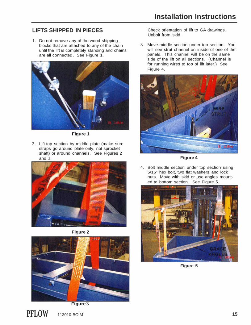
LIFTS SHIPPED IN PIECES
1. Do not remove any of the wood shippingblocks that are attached to any of the chainuntil the lift is completely standing and chainsare all connected . See Figure 1.
Figure 1
2. Lift top section by middle plate (make surestraps go around plate only, not sprocketshaft) or around channels. See Figures 2and 3.
Figure 2
PFLOW 113010-BOIM
Check orientation of lift to GA drawings. Unbolt from skid.
3. Move middle section under top section. Youwill see strut channel on inside of one of thepanels. This channel will be on the sameside of the lift on all sections. (Channel isfor running wires to top of lift later.) SeeFigure 4.
Figure 4
4. Bolt middle section under top section using5/16" hex bolt, two flat washers and locknuts. Move with skid or use angles mount-ed to bottom section. See Figure 5.
Figure 5
15
Figure 3

8 Series
Figure 6
5. Repeat placing bottom section under middlesection and bolt the same way. Be carefulnot to pinch wires in strut channel. SeeFigure 9.
To align sections (Figure 6), use alignment pin to get edges on bolt strip even. Hold with vice grip pliers and remove alignment pin and bolt with above-mentioned hard- ware. In some circumstances, you may have to loosen bolts above or below strip to get them to align (Figure 7). This is okay. After the section is all bolted together, go back and retighten those bolts again.
Figure 7
If you must move the entire section to get close to alignment, use a plastic sledgeham- mer on the edges only of the sections and not on flat sides of panels. See Figure 8.
Figure 8
16
NOTE Remove the two angles prior to this (Figure 10).
NOTE The angles can be used to lift section off skid and move section if needed.
Figure 10
113010-BOIM PFLOW
Figure 9

Installation Instructions
Anchoring & Bracing - See Figures 11, 12, and page 5.
6. Anchor four corners inside of lift using mini-mum or 3/8" diameter anchors in all four cor- ners (inside lift under carriage). You maywant to do this after carriage is raised toupper location. See Figure 11.
CAUTION Do not work under the carriage unless it is properly and safely supported and elec- trically tagged and locked out.
Figure 11
7. Use angle attachments to brace unit. Drillthrough unit flanges to attach to unit. Useshipping angles that are provided to attach tothe customer's building, mezzanine, etc. SeeFigure 12.
NOTE You may use one existing flange bolt and then drill and bolt through other hole.
Figure 12
PFLOW 113010-BOIM
Use lifting angles to brace unit if needed. Bolt through a flange and to mezzanine or building.
8. Remove access cover below lower levelgate to gain access to control panel cables.Feed cable (PB1) through hole with grom-met in lower panel and to where you havemounted push button station near lowerlevel gate. Secure cables inside and out-side of lift so they don't interfere with movingparts of lift. Match wire tag to device. SeeFigure 13.
Figure 13
9. Run upper electrical component cables upback panel in unistrut and secure with cov-ers. Route wires to appropriate components(wire markers) securing around top of lift outof way of any moving parts. Run push but-ton cable over top of lift and down alongedges to push button station mounted neargate handle. Secure cable out of way. SeeFigures 14, 15 and 16.
17

B Series
Figure 15
Figure 16
NOTE Cables might be run through different rings than shown in picture . Cables were pre- mounted and wire tied, so run through the obvious route.
18 113010-BOIM PFLOW
Figure 14

Figure 19
Installation Instructions
10. Attach push button brackets to one of thebolts holding horizontal edge of lift sidestogether. See Figure 17.
Figure 17
11. Uncoil lift chains which are in the top sectionof the lift. The chains are temporarily heldfrom rolling over sprockets by bolts throughthe chain and into a wood block on top ofthe lift. After you connect chains to top ofcarriage and to loose ends of chain behindcarriage, you can remove blocks fromchains. See Figures 18, 19, 20 and 21.
Figure 18
PFLOW 113010-BOIM
Figure 21
You may have to lift carriage slightly to attach chains. Use come-along, if needed. After all ends of chains are connected, you must remove all wood blocks.
CAUTION If you need to lift carriage up, you must move wood block up higher on chain See Figure 18. Be careful not to lift carriage too much, or you will stretch springs under car- riage.
19
Figure 20

B Series
If chains seem short, check bottom sprockets and make sure chain is not bunched up by sprockets and jump guide. See Figure 22.
Figure 22
12. The return end of chain should already beattached to bottom of carriage via springs. Thereshould be enough tension on springs to keepchain tight around sprockets on motor when lift isat upper level. If more tension is needed, adjustwith bolts. See Figure 23. (Springs shouldextend approximately 4".)
Figure 23
13. After carriage is hanging from lift chains, backsafety pin retaining nuts all the way to the "eye" ofeye bolt. Lock into place. The safety pins arenow ready to actuate if chains break. See Figure24. Pins should stick past housing approximately3/8". Adjust turnbuckle, if needed See Figures24 and 25.
20
NOTE To adjust pins, carriage must be hanging free by the chains. You may have to wait until you raise the carriage slightly during start up to do this step.
Figure 25
14. Bring power (proper voltage) to 4" boxmounted on lower section of lift. See Figure26 .
CAUTION Before wiring, check the voltage on the general arrangement drawing. Wrong voltage will destroy inverter.
Before running lift, make sure cables and chains are clear of moving carriage.
Figure 26
113010-BOIM PFLOW
Figure 24

Installation Instructions
A DJ USTM ENTS IF N EEDED
1. Adjust plate up and down or interlock keeperleft or right to align into interlock. Adjustmagnet to hold gate shut. See Figure 27.
Figure 27
4. If arm adjustment is needed, loosen nut byeyebolt and set screw in end of bar. Do notgo much past vertical with white rub rubblock. It must be able to pivot down pastend of bar. If it pivots the wrong direction, itwill jam device. See Figure 30.
2. Adjust overtravel switch so carriage won'trun into interlock or top lift components.See Figure 28. START UP
Figure 30
1. Make sure all wood blocks are removedfrom chain and top of carriage chain mount.
2. Close gates and pull out e-stops .
3. Make sure chain break block does not hitreducer before actuating. See Figure 29.
3. Run unit up approxi-mately one foot andpush red e-stop onpush button stationto confirm it works .Look at safety pinson top of carriage toensure they willclear catch stripsand are centered inslots in strip. If side-to-side adjustment isneeded, loosen boltsand tap pin housing.Also, make sure pinsare approximately3/8" out of housing.See Figure 31.
Figure 31
Figure 29
PFLOW 113010-BOIM
4. With someone at upper level near e-stop,run carriage up to second level. It shouldstop via the interlock I stop switch . If itstops on the overtravel, you will have to re-adjust interlock I stop switch arm to engagecarriage sooner or adjust overtravel switchto engage later. Also, carriage should not"bottom out" or "top out" against any physi-cal stops .
21
Figure 28

B Series
(THIS PAGE INTENTIONALLY LEFT BLANK)
22 030609 BOIM PFLOW

1. Main Control Panel (inside lower portion ofunit)
2. Gear/Motor Unit (inside lower portion ofunit)
3. First Level Push Button Station4. Second Level Push Button Station
Electrical Overview Series B
ELECTRICAL OVERVIEW
NOTE The following is a standard description of the electrical wiring of the VRC ONLY. It DOES NOT include specifics on options available or ordered. A copy of the schematic can be found in a manila enve- lope in the parts crate.
All electrical devices are tied into the MAIN CONTROL PANEL.
PFLOW 112311-EIG-B
PUSH BUTTON STATIONS. One station is nor- mally supplied for each level. ANSI/AME B20.1 code requires that they be remotely located so they cannot be activated by someone standing on the carriage. Each station has an UP, DOWN, and EMERGENCY STOP button.
The UP and DOWN switches are momentary contact. This allows the operator to depress the button and let go. The EMERGENCY STOP button is pushed to activate but will stay in and must be pulled back out for the unit to operate.
Required by NEC code, the MAIN DISCON- NECT should be fused, lockable, and located within line of sight of the control panel. (Not supplied by Pflow.)
& WARNING
All gates or doors accessing the lift area must be electro-mechanically INTERLOCKED. This requires electri- cal contacts to prevent the lift from operating if a gate is open when the carriage is at that level and mechani- cal locks to lock the gate until the carriage is at that landing.
Different types and styles of interlocks are sup- plied depending upon the type of gate and on- site conditions . Standard styles incorporate from one to four electrical components per gate.
8185-23

Electrical Overview Series
(THIS PAGE INTENTIONALLY LEFT BLANK)
112311-EIG-B PFLOW

PUSH-BUTTON STATION
EIGHT-PIN CONNECTOR
Quick-Connect Cabling for Series B Mechanical Units
Connectors are factory installed in the control panel. Pflow Industries provides quick-connect cables that have a screw-on connector at one end that attaches to the push button stations, gate interlocks, limit switches and a screw-on connector at the other end that plugs into the connector in the control panel.
1. Install interlocks, push-button stations and limitswitches;
2. Route cable to push-button station(s),interlock(s), limit switches and control panel.
Cables should be installed inside the column or in anarea where they will not hang loose. Use tie wraps toloop and secure excess cable.
If additional cabling is required, Pflow stocks extension cables that may be installed between the existing cable, the interlocks, push-button stations and limit switches. Call if these are needed. Standard cables are three-pin for interlocks, five-pin for limit switches and eight-pin for push-button stations.
SERIES B
PFLOW INDUSTRIES, INC., 6720 North Teutonia Avenue , Milwaukee, WI 53209 (414)352-9000 ; FAX (414) 352-9002; 043002/013012
PFLOW 013012-BOIM 8306-8-25
SWING GATE INTERLOCK
THREE-PIN CONNECTOR
LIMIT SWITCH
FIVE-PIN CONNECTOR

Quick-Connect Cabling for Series B Mechanical Units
Your Pflow Industries Series 8 vertical conveyor is supplied with pre-installed electrical quick- connect connectors for the interlocks, push-button stations and limit switches. These connec- tors are factory installed in the control panel. Pflow Industries provides quick-connect cables that have a screw-on connector at one end that attaches to the push button stations, gate interlocks, limit switches and a screw-on connector at the other end that plugs into the con- nector in the control panel.
This factory-supplied cabling system is well accepted by industry and is rapidly becoming a standard at major automotive companies such as GM, Ford, and Chrysler.
Pflow is offering this system with the hope of reducing field installation costs by allowing the mechanical installers to both mount and hook up the interlocks, push-button stations and limit switches without the services of an electrical contractor. This would also allow the installation to be completed in one trip.
Pflow does not currently provide any wireway or protective covers to aid in routing these cables.
The quick-connect cables are not covered by a specific local, state, or federal code nor by any code guarantee from Pflow. It is important for the customer to understand that local inspectors may not be familiar with this type of cabling system and may want the unit hooked up with EMT or rigid conduit.
Resellers should include a disclaimer that hookup of devices is included as long as the cus- tomer and local authorities accept the factory quick-connect cabling system. Costs associat- ed with rework on the job to add EMT or conduit will not be covered by the reseller or Pflow Industries.
As Pflow gathers more field data on these quick-connect cables, we will share that informa- tion with you.
PFLOW INDUSTRIES, INC., 6720 North Teutonia Avenue, Milwaukee, WI 53209 (414)352-9000; FAX (414) 352-9002; 043002/013012
013012-BOIM PFLOW

Warranty
WARRANTY PARTS Structure ....................................................Lifetime Manufactured Components ....................One Year Purchased Components .........................One Year
The Small Print
LABOR Structure ..........................................Lifetime Manufactured Components ..........One Year Purchased Components ................90 Days
The warran!Y period begins 30 days after shipment. All warranty work must be pre-authorized by Pflow Industries' Product Support Department prior to starting work. All billing must be in accordance with our Warranty Procedures. Replacement of defective parts will be handled m accordance with Pflow's Return Goods Authorization policy. If Pflow Industries determines that equipment failures were caused by abuse, improper installation, or lack of maintenance, they will not be covered. Pflow Industries will not accept consequential losses (missed production, etc.), premium time labor, or air freight charges.Manufactured items are defined as those components manufactured and/or assembled oy Pflow.Structure is defined as columns and carriage (excluding carriage side guards). Purchasea items are those components that are used as supplied by vendors. Gates and enclosures are excluded and cov- ered for 90 days parts and labor. This warranty applies to all models and may not be modified or extended except by written authorization from Pflow Industries, Inc.
We, the manufacturer, sincerely hope that you do not experience problems with the equipment. If you do, the following procedures snould be followed:
Pre-Authorization
Pflow Industries must be notified of the problem before we can authorize the repair. We need to deter- mine the cause of the problem, who should be doing the work, and what is involved. If it is our decision to have your organization or your subcontractor do the work, you will be given an authorization number which must be referenced on all subsequent paperwork. During our non-working hours, we ask that you notify us by phone or FAX during the next business day.
Issuance of an authorization number does not guarantee approval and/or payment.
Invoices
1. You have 30 days from the date the work was completed to submit an invoice for approval. Ifapproved, payment is made 30 days from the date of approval.
2. A deduction from outstanding payments to Pflow for warranty is NEVER authorized and will result ina 10% processing fee.
3. Invoices received without sufficient information will be returned. They will be reconsidered for1=J.pproval when complete documentation is received. All invoices must include, in detail, the follow- ing:
- Description of problem; - Pflow serial number; - Labor hours per problem; - Rate per hour; - Travel time incurred; - Date work was performed; - Copies of receipts for materials purchased locally or labor subcontracted.
Comments
Pflow Industries is not responsible for payment made on claims prior to our approval.
Local purchase of components must be pre-authorized.
Where distance and/or experience may be more cost-effective, Pflow Industries reserves the right to use alternate organizations.
Labor is defined as a maximum of two hours travel per call, plus reasonable on-site repair time as determined by Pflow Industries.
PFLOW 030609-BOIM 27

B Series
(THIS PAGE INTENTIONALLY LEFT BLANK)
28 113010-BOIM PFLOW

Maintenance Instructions
B LIFT MAINTENANCE
1. Oil chains as needed. (Don't over oil chain.Chain is above the load and may drip. Useno-drip lube if deemed necessary.)
2. Inspect safety pins for free movement.(Loosen turnbuckles to check for engage-ment. Retighten turnbuckles before run-ning.) See page 15, #11.
3. For switch adjustment, see page 16.
PFLOW 113010-BOIM 29

Maintenance Instructions
(THIS PAGE INTENTIONALLY LEFT BLANK)
30 113010-BOiM PFLOW

Parts
RECOMMENDED SPARE PARTS LISTING
This recommended spare parts list is a guide to assist you in establishing an emergency inventory for your Pflow Vertical Reciprocating Conveyor. Convenience and minimal down time are two good reasons to maintain an inventory of spare parts. This list does not imply that any part is subject to failure. However, should any of these parts fail, they could place the unit out of service. Establishing a routine inspection and preventive maintenance program will add life and decrease the probability of down time.
Quantity Part Number Description
Lift Components
1 13197-0000 1 13225-4016-22 1 JXXXX-XXXX 1 2690-1000
Sprocket, 40 A18 Sprocket, 40 A16 Gearmotor Interlock. GAL
1 2891-0000
Electrical Components
Arm, Limit Switch 1 13692-0014 Operator, M.H.P.B., Red Push-Pull1 13690-0003 Operator, P.B., Flush, Black1 13969-0052 Contact Block, 1NC1 13969-0051 Contact Block, 1NO1 EN708-0322 Relay, 2PDT, 12VDC1 13675-1002 P. B. Station, Quick Connect1 2893-1000 Limit Switch1 15235-2006 Cable, M12 8-Pin, 6M1 15235-2010 Cable, M12 8-Pin, 10M1 15233-2002 Cable, M12 5-Pin, 2M1 15233-2006 Cable, M12 8-Pin, 6M1 15233-2010 Cable, M12 5-Pin, 10M
This is not a formal quote and is intended for reference and recommendation only. Prices and part numbers are subject to change or correction without notice. Minimum order charge $35. FOB Milwaukee, WI. A $50 Rush Fee may be charged for requested same day shipments. Components replaced under warranty will be charged for in accordance with our RGA procedures. Pflow Industries Product Support must issue an authorization in advance of any claim for warranty and/or warranty labor. This list is based on the above serial number as manufactured and shipped new from Pflow Industries. Any changes, updates, parts by others or modifications are unknown to Pflow Industries.
Pflow Industries, Inc., 6720 North Teutonia Ave, Milwaukee, WI 53209 Phone (414) 352-9000 Fax (414) 352-9002
Establishing a routine inspection and preventive maintenance program will add life and decrease the probability of down time.
113010-BOIM 31

Item I Qty I Description Length j1
Material j Port. Number WGT./EA.
ill.&
3
=======================
GREASE PIN AT ASSEMBLY
1--- ----
0-1( 6")
0- ---- --t
This print including \he desiqn and principles ofconstruction . is the property of Pr-low Industries, Inc. ond must be return-ed on demond. The infor-motlon contained
IJMWOT>ifR'.VltH.u:'IC.i;:iEQi _.4J.l(SIOIJSAFf.ll fllCtiES. PFIOW PFLOWI
di f; ittigl[i<e:., s 6 61°ti t 1auf s.n'?;,c.NOUSTRIES.INC. 414-35MOOO
B
A
REV.
9/10/2010
12I22/09DATE
SJD
OMS
BY
10.033
09.058
ECN
1 "=,.;,_ 'i.!1&:' •' .!' '.'. ·· x
REVISIONS
tMCti._,.\:,;.i·DO tlOI SCALE DAAWING!
MAl'ERIAl
REF.(NUMBft)
SAFETY STOP, PINASSY
DATE03-26-96
_ DRAWN DMB
SCALE
CHEC•m
1:1 PIAWINGNUMI..
9644-0000-B Of BHI 1 IREV
DATE PRINTED: 12/1/2010
0
OJ
.,,
C"J))
"'C Q)
PIN, SAFETY STOP r•1-s.1 C'?•'t• ·r, !; ..1 ( 9645-0000 0
2 1 PIN, SAFETY STOP, WELDMEN 9646-0000 2
3 1 SPRING, COMPR, .480 OD i"l':l<I \ nrbtm oi;t1"11 I 9521-0000 0
4 2 HNUT 1/4-20 GR 2 6358-0009
5 1 EYEBOLT, 1/4-20 x 4, FULL P1oi11 \..Qt\>.11'1 $<..,rd I 13834-0064 I 0
->. ->.
UJ' 0 ->.
I
0 $;
.,, ii

5
I
-..,:,i.',
II Item Qty Description Length I Material I Part Number I WGT./EA.
l 1 ROLLER, CARRIAGE, UHMW I UHMW I 13153-0000 0
......
.....>.
c..v 2 l ANGLE, MTG, CARR ROLLER I 6061-T6 ISSJ I 13289-1000 0
. I I I I I I 0 c'o
3 I BOLT, SHLDR, 3/8 X l/2 Plain Carbon Steel 7018-0008
I )=Lil t [ I:} I 4 2 SCREW,HHC,3/8- l6X l.O,GR2 Plai bon I 5927-0016'\ I
5 2 LOCKWASHER, 3/8 Plai bon I 5858-0011
--
II =l " I 6 1 I NUT, HEX, JAM, 3/8-16 I
Plain
bon I 8326-001 l
T6 1 1 1.L"16
( i" )
( 01i" ) ( 3t" )
I
jI I I
( 2t" )
This print including the desin and principles of construction is the property of Pflow Industries, Inc. and must be returned on demand. The information contained
hereon is confidential and may not be used nor divulged without permission of Pflow Industries, Inc.
UNLESS OTllERWISE IMDICATED : ALL DIMENSIONS ARE IN INCMES.
!Ol.ERANCE.S:fRACTIONAl !l/16 DECIMAL .XX!.03
.xxx:.015ANGULAR : 1
DO NO ·Lst ;: s1,
PFIOW 11..t:.
:_uw 1\ •.IJ 1..:11:.s, 1N1 F.7 '.) f\ :'h r.::utnr'1:- 1\\ ':!
t ·1ilw·1ul<t-:.-:, V./I ::i "'i;· ::i
ROLLER AY, CARRIAGE ALUMINUM ANGLE
·I I'-,) -·-.. :11.·1·1 --5•'.::'.-:UI/..: r,.,1 i1 •,,o:.1.1 fl• • N < '
"1J I•11 1 :.-11•1 I 09-29-2009 1., :..',.. 1:1 1'""" '13293-1000-B fi' V
1;L1 ·.:: · .11u11·1 i:;uo1ni DMB '
w w
" 1 1 A ·
------·--·-····-·-----------
0

I
-.,,
CA> I ""tJ-1::1• m
it
w 0
0
OJ 0
.,, 01
'\. . . 6 /
0 0 0
const itignfu i7 u gp t'y ?to"1nJ' ;/ 51n'. and15must be returned en demand. The information contained
dif tg rd;is :;J0 t1 t 1auf s."?c.VNl£SS OJHER', JSE •CICP.TED:
AU OIMEP:$0t1$ AREIN r-iCH'ei.
;tf.':,l.CfO'W. 1:1114 PFm PFl.OW INDUSIF.S, INC.6720 Horth Teutonlo A.
1lih'l(J1Jitei.1, WI 53209
414-352-9000414-352-9002 r:AK;nfo@:>fk·,w.c:orn
OOCIMAl L03 '- --------------------"P.X1:.ois
1-------- -CHANG-ED-IT-12- DESCRIPTION--------1--
A--1-
1-0-=/4-/-2'-0-1-0-i--
SWK--l
OO tzorSCALE DAAWINGI
,.....,,,.,.,=;.,. GAL ASSY, SERIES B
REV. DATE BY hi,i:,i,,,,,.,,,,,;..;..;..:....::..=c--"'-ll::":'."""-=06"'°-1"a''"2"=009,.,,,....",,,. ----.-.,0,,••"·"''""'"""'"'"""'"''"'',..---
JOB REVISIONS _ """'MRR18
'"'"·' .
-13296-0000-B
-r,,,,.,,-:- "'"':'',---j" I A
·: 12/1/2010
Item I Qty I Description Port Number WGT./EA.
SUPPORT, KEEPER-INTERLOCK 13190-0000 13
2 1 MTG PLATE, GAL 13294-0000 3
3 1 INTLK, GAL LH, TYPE N, QD 2691-1100 10
4 1 PIN, ROLL 3/16 x 2 5209-0032
5 1 SHLDR 3/8 x 1 1/2 7018-0024
6 1 ARM, LIMIT SWITCH 13226-0000 07 1 BLOCK, LIMIT SWITCH 13227-0000 I 0
8 2 HCS 5/16-18 x 1 1/2 GR 2 6846-0024
9 4 FW USS 5/16 6296-0010
10 2 LW 5/16 5858-0010
11 2 HNUT 5/16-18 GR 2 6.358-0010
& 1 12 1 SCREW, BHSC 10-32x1-1/4 113690020
13 1 SPRING, EXTENSION HK ENDS 13671-0000 I 0

Junction boxcalled out on -0301 electricalcontrol dwg.
( 46t" )
V
3I
-a1 -.,1
Ii Item I QTY Description Part Number I WGT./EA.
._......
. w
FRAME LOWER, WLDMT I 13195-3600 80
.... 2 2 ! SPROCKET, 40813, 1 1/8" 13225-4013-18 0 0 ------------f-- --'-----''- 1 ----------------------- 1 CD 2 I CHAIN JUMP GUIDE, TUBE 13285-1000 0
s: 4 CHAIN TENSIONER L/S AY RH I 13662-1001 2
5 CHAIN TENSIONER L/S A Y LH I 13662-1000 2
6 BRKT, MTG, CONTROL PANEL 1 13831-0001 7
7 4 I SCREW,HHC,1 /4-20X.75,GR2 6029-0012 0
8 4 I LOCK WASHER, STD, 1/4 5858-0009 0
9 4 I WASHER, FLAT, STD 1/4 6296-0009 0
10 4 I NUT, HEX, 1/4-20, GR2 6358-0009 0
11 2 I SCREW,HHC,3/8-16X.75,GR2 1 5927-0012 0
12 2 I SCREW, BHSC, 3/8-16 X 5/8 1 8399-0010 0
13 4 I LOCK WASHER, 3/8 5858-0011 0
13827-3610 LOWER FRAME A Y, RH Junction box on nghf side
13827-361 1 LOWER FRAME A Y, LH Junction box on left side
14 2 I WASHER, FLAT, STD 3/8 6296-0011 0
15 2 I WASHER, FLAT, 3/8, SAE 7768-0011 0
WGT: 147
6 ASSEMBLY USES CHAIN TENSION AY WITH CH LIMIT SWITCHES.
( io.i" ) l
NORD SK 1S163L GEA RMOTOR ON -0100 BOM
AULLNlDESIMSOElll<iESRIOWNOSEAUR<ED"iCINACJEMOES., I PFIow 101ERANCES :fkACUONAL .t ll\6
:r _1JW l \;l.J'....· 1..:11:.· . 1N1
F. 7'. nl ,.\:\J,\:.,T"\};\ t \;: : · \
·I I" -:'· "'-'"1 .!!; .j 1-- ::,,".;- 1)1 •'..: 1-,.. ,,11·..v1 11.. 'I ·
c..>
OECitML .XX!.OJ .xxx .t.015
. , ANGULAR ::I" MACt. SURFACf flNISti: 250
DO NO'f SCALE DRAWING! 01-31-2013 r: :..'
LOWER FRAME AY. RH
1:81,-. ''\3827-3610-B "-''
01 I1;LI ."!.:: ·..!11.lTI• - 1 "'"·" MRR ,, I " 1
I

- ··-···. -· -- -··-··-·· -·-·---·· --···-----··· - ... ·----- -·- ------·-·------,·---------------·---------.._. ,_ . -·-·-·------,··-

B Series
(THIS PAGE INTENTIONALLY LEFT BLANK)
36 113010-BOIM PFLOW

Installation Questionnaire
We want to provide equipment that is built correctly and shipped complete. To achieve that, we need to know what errors are being made or what field problems you are experiencing. Please answer the following questions and return this form to the Product Support Department at Pf/ow Industries, Inc. If more space is required for comments, please use the reverse side.
1. Was the unit received in good condition? Yes I NoIf not, please describe damage: _
2. Was the unit received complete? Yes I NoIf not, what was missing? _
3. Was the lift manufactured correctly? (Did it match the GA drawing?) Yes I NoIf not, please describe the errors: _
4. Did the unit (i.e., lift, gates, enclosures) fit? Yes I NoIf not, please describe in detail the problem areas: _
5. Did you return after the electrical was completed for final adjustments, testing, and training?Yes I No
If No, were you able to hook up temporary power to test the unit and make all final adjustments? Yes I No
If Yes, were there electrical problems that you were aware of? Was there a problem with the components? Yes I No
If yes, please describe: _
Was there a problem with the field wiring? Yes I No If yes, please describe: _
6. Did you test the unit to full capacity? Yes I No
7. Did you test all gates to make sure that the unit does NOT operate if they are open? Yes I No
8. At each level, when the carriage is NOT present, can you open the gate? Yes I No
Comments: _
Pflow Job #: Customer/User: _
Questionnaire Completed By: Date:
_
Company:, Phone: _
PFLOW INDUSTRIES, INC., 6720 North Teutonia Avenue, Milwaukee, WI 53209 Phone (414) 352-9000; Fax (414) 352-9002; 040199

PFLOW 113010-BOIM 37

8 Series
(THIS PAGE INTENTIONALLY LEFT BLANK)
38 113010-BOIM PFLOW

Acceptance Certification
We accept this equipment as being properly installed, tested, and performing to our satisfaction. This form covers both the mechanical and electrical installation of the equipment and is for the purpose of quality assurance by Pf/ow Industries, and in no way releases either Pf/ow Industries, Inc. or the installing contractor(s) of their warranty obligations. If there are any exceptions or unresolved items, please note.
Site Mailing Address: _
City, State, Zip Code: _
On-Site Contact for future follow-up:
Name: Title: _
Phone: ( ) _ Ext. _
Tests Successfully Performed: .Load test at % of capacity Operation
Gate/Interlock Operation Other: _
Personnel Instructed on the Operation:
Name: Company: _
Name: Company: _
ACCEPTED BY:
Date: _ Date:------------- Name:--------------- Name: _
Title: _ Title: _
Company: _
Phone: _
Company: _
Phone: _
PFLOW PERSONNEL I REPRESENTATIVE I INSTALLER PRESENT:
Date: _
Name: Company: _
Please return a copy of this form to the Product Support Department.
PFLOW INDUSTRIES, INC., 6720 North Teutonia Avenue, Milwaukee, WI 53209 Phone (414) 352-9000; Fax (414) 352-9002; 040199
PFLOW 113010-BOiivi 39

B Series
(THIS PAGE INTENTIONALLY LEFT BLANK)
40 113010-BOiivi PFLOW

Appendix
PFLOW 013012-BOIM 41

Appendix
(THIS PAGE INENTIONALLY LEFT BLANK)
42 013012-BOiM PFLOW

MATERIAL SAFETY DATA SHEET
F78XXL13851-4357 00 01
DATE OF PREPARATION Dec 21, 2013
PRODUCT NUMBER F78XXL13851-4357
PRODUCT NAME Fast Dry Acrylic Enamel, FDA PFlow Blue VOC
MANUFACTURER'S NAME THE SHERWIN-WILLIAMS COMPANY 101 Prospect Avenue N.W. Cleveland, OH 44115
Telephone Numbers and Websites Regulatory Information (216) 566-2902
Medical Emergency (216) 566-2917 Transportation Emergency* (800) 424-9300
*for Chemical Emergency ONLY (spill, leak, fire, exposure, oraccident)
N:/15xxx/15713-0011 01/08/14 page 1 of 6
SECTION 1 — PRODUCT AND COMPANY IDENTIFICATION

F78XXL13851-4357
% by Weight CAS Number Ingredient Units Vapor Pressure 4 64742-89-8 V. M. & P. Naphtha
ACGIH TLV OSHA PEL OSHA PEL
300 PPM 12 mm300 PPM 400 PPM STEL
9 108-88-3 TolueneACGIH TLVOSHA PEL OSHA PEL
20 PPM100 ppm (Skin) 150 ppm (Skin) STEL
22 mm
4 100-41-4 Ethylbenzene ACGIH TLV 20 PPM 7.1 mm OSHA PEL 100 PPM OSHA PEL 125 PPM STEL
22 1330-20-7 Xylene ACGIH TLV 100 PPM 5.9 mm ACGIH TLV 150 PPM STEL OSHA PEL 100 PPM OSHA PEL 150 PPM STEL
24 67-64-1 Acetone ACGIH TLV 500 PPM 180 mm ACGIH TLV 750 PPM STEL OSHA PEL 1000 PPM
4 110-19-0 Isobutyl Acetate ACGIH TLV 150 PPM 12.5 mm OSHA PEL 150 PPM
1 108-65-6 1-Methoxy-2-Propanol Acetate ACGIH TLV Not Available 1.8 mmOSHA PEL Not Available
3 112926-00-8 Amorphous Precipitated SilicaACGIH TLV 10 mg/m3 as DustOSHA PEL 6 mg/m3 as Dust
2 14807-96-6 Talc ACGIH TLV 2 mg/m3 as Resp. DustOSHA PEL 2 mg/m3 as Resp. Dust
4 13463-67-7 Titanium DioxideACGIH TLV 10 mg/m3 as DustOSHA PEL 10 mg/m3 Total Dust OSHA PEL 5 mg/m3 Respirable Fraction
0.3 1333-86-4 Carbon BlackACGIH TLV 3.5 MG/M3OSHA PEL 3.5 MG/M3
ROUTES OF EXPOSURE INHALATION of vapor or spray mist. EYE or SKIN contact with the product, vapor or spray mist.
EFFECTS OF OVEREXPOSURE EYES: Irritation. SKIN: Prolonged or repeated exposure may cause irritation.
INHALATION: Irritation of the upper respiratory system.
HMIS Codes
May cause nervous system depression. Extreme overexposure may result in unconsciousness and possibly death. Prolonged overexposure to hazardous ingredients in Section 2 may cause adverse chronic effects to the following organs or systems:
the liver the urinary system the hematopoietic (blood-forming) system the cardiovascular system the reproductive system
SIGNS AND SYMPTOMS OF OVEREXPOSURE Headache, dizziness, nausea, and loss of coordination are indications of excessive exposure to vapors or spray mists. Redness and itching or burning sensation may indicate eye or excessive skin exposure.
MEDICAL CONDITIONS AGGRAVATED BY EXPOSURE None generally recognized.
CANCER INFORMATION For complete discussion of toxicology data refer to Section 11.
N:/15xxx/15713-0011 01/08/14 page 2 of 6
SECTION 3 — HAZARDS IDENTIFICATION
SECTION 2 — COMPOSITION/INFORMATION ON INGREDIENTS
Health 2* Flammability 3
Reactivity 0

F78XXL13851-4357
EYES: Flush eyes with large amounts of water for 15 minutes. Get medical attention. SKIN: Wash affected area thoroughly with soap and water.
Remove contaminated clothing and launder before re-use. INHALATION: If affected, remove from exposure. Restore breathing. Keep warm and quiet. INGESTION: Do not induce vomiting. Get medical attention immediately.
FLASH POINT 1 °F TCC
EXTINGUISHING MEDIA
LEL 0.9
UEL 13.1
FLAMMABILITY CLASSIFICATION RED LABEL -- Extremely Flammable, Flash below 21 °F (-6 °C)
Carbon Dioxide, Dry Chemical, Foam UNUSUAL FIRE AND EXPLOSION HAZARDS
Closed containers may explode when exposed to extreme heat. Application to hot surfaces requires special precautions. During emergency conditions overexposure to decomposition products may cause a health hazard. Symptoms may not be immediately
apparent. Obtain medical attention. SPECIAL FIRE FIGHTING PROCEDURES
Full protective equipment including self-contained breathing apparatus should be used. Water spray may be ineffective. If water is used, fog nozzles are preferable. Water may be used to cool closed containers to prevent pressure
build-up and possible autoignition or explosion when exposed to extreme heat.
STEPS TO BE TAKEN IN CASE MATERIAL IS RELEASED OR SPILLED Remove all sources of ignition. Ventilate the area. Remove with inert absorbent.
STORAGE CATEGORY DOL Storage Class IB
PRECAUTIONS TO BE TAKEN IN HANDLING AND STORAGE Contents are EXTREMELY FLAMMABLE. Keep away from heat, sparks, and open flame. Vapors will accumulate readily and may ignite
explosively. During use and until all vapors are gone: Keep area ventilated - Do not smoke - Extinguish all flames, pilot lights, and heaters - Turn off
stoves, electric tools and appliances, and any other sources of ignition. Consult NFPA Code. Use approved Bonding and Grounding procedures. Keep container closed when not in use. Transfer only to approved containers with complete and appropriate labeling. Do not take internally.
Keep out of the reach of children.
PRECAUTIONS TO BE TAKEN IN USE Use only with adequate ventilation. Avoid contact with skin and eyes. Avoid breathing vapor and spray mist. Wash hands after using. This coating may contain materials classified as nuisance particulates (listed "as Dust" in Section 2) which may be present at hazardous
levels only during sanding or abrading of the dried film. If no specific dusts are listed in Section 2, the applicable limits for nuisance dusts are ACGIH TLV 10 mg/m3 (total dust), 3 mg/m3 (respirable fraction), OSHA PEL 15 mg/m3 (total dust), 5 mg/m3 (respirable fraction).
VENTILATION Local exhaust preferable. General exhaust acceptable if the exposure to materials in Section 2 is maintained below applicable exposure
limits. Refer to OSHA Standards 1910.94, 1910.107, 1910.108. RESPIRATORY PROTECTION
If personal exposure cannot be controlled below applicable limits by ventilation, wear a properly fitted organic vapor/particulate respirator approved by NIOSH/MSHA for protection against materials in Section 2.
When sanding or abrading the dried film, wear a dust/mist respirator approved by NIOSH/MSHA for dust which may be generated from this product, underlying paint, or the abrasive.
PROTECTIVE GLOVES Wear gloves which are recommended by glove supplier for protection against materials in Section 2.
EYE PROTECTION Wear safety spectacles with unperforated sideshields.
OTHER PRECAUTIONS Intentional misuse by deliberately concentrating and inhaling the contents can be harmful or fatal.
N:/15xxx/15713-0011 01/08/14 page 3 of 6
SECTION 8 — EXPOSURE CONTROLS/PERSONAL PROTECTION
SECTION 7 — HANDLING AND STORAGE
SECTION 6 — ACCIDENTAL RELEASE MEASURES
SECTION 5 — FIRE FIGHTING MEASURES
SECTION 4 — FIRST AID MEASURES

SECTION 9 — PHYSICAL AND CHEMICAL PROPERTIES
F78XXL13851-4357
PRODUCT WEIGHT 7.84 lb/gal 939 g/l SPECIFIC GRAVITY 0.94
BOILING POINT 132 - 325 °F 55 - 162 °C MELTING POINT Not Available
VOLATILE VOLUME 77% EVAPORATION RATE Slower than
ether VAPOR DENSITY Heavier than air
SOLUBILITY IN WATER Not AvailableVOLATILE ORGANIC COMPOUNDS (VOC Theoretical - As Packaged)
4.90 lb/gal 588 g/l Less Water and Federally Exempt Solvents 3.52 lb/gal 422 g/l Emitted VOC
STABILITY — Stable CONDITIONS TO AVOID
None known. INCOMPATIBILITY
None known. HAZARDOUS DECOMPOSITION PRODUCTS
By fire: Carbon Dioxide, Carbon Monoxide HAZARDOUS POLYMERIZATION
Will not occur
CHRONIC HEALTH HAZARDS Reports have associated repeated and prolonged overexposure to solvents with permanent brain and nervous system damage. Ethylbenzene is classified by IARC as possibly carcinogenic to humans (2B) based on inadequate evidence in humans and sufficient
evidence in laboratory animals. Lifetime inhalation exposure of rats and mice to high ethylbenzene concentrations resulted in increases in certain types of cancer, including kidney tumors in rats and lung and liver tumors in mice. These effects were not observed in animals exposed to lower concentrations. There is no evidence that ethylbenzene causes cancer in humans.
IARC's Monograph No. 93 reports there is sufficient evidence of carcinogenicity in experimental rats exposed to titanium dioxide but inadequate evidence for carcinogenicity in humans and has assigned a Group 2B rating. In addition, the IARC summary concludes, "No significant exposure to titanium dioxide is thought to occur during the use of products in which titanium is bound to other materials, such as paint."
Carbon Black is classified by IARC as possibly carcinogenic to humans (group 2B) based on experimental animal data, however, there is insufficient evidence in humans for its carcinogenicity.
N:/15xxx/15713-0011 01/08/14 page 4 of 6
SECTION 11 — TOXICOLOGICAL INFORMATION
SECTION 10 — STABILITY AND REACTIVITY

F78XXL13851-4357
TOXICOLOGY DATA
CAS No. Ingredient Name 64742-89-8 V. M. & P. Naphtha
LC50 RAT LD50 RAT
4HR Not Available Not Available
108-88-3 Toluene LC50 RAT LD50 RAT
4HR 4000 ppm 5000 mg/kg
100-41-4 EthylbenzeneLC50 RAT LD50 RAT
4HR Not Available 3500 mg/kg
1330-20-7 Xylene LC50 RAT LD50 RAT
4HR 5000 ppm 4300 mg/kg
67-64-1 Acetone LC50 RAT LD50 RAT
4HR Not Available 5800 mg/kg
110-19-0 Isobutyl AcetateLC50 RAT LD50 RAT
4HR Not Available 13400 mg/kg
108-65-6 1-Methoxy-2-Propanol Acetate LC50 RAT 4HR Not Available LD50 RAT 8500 mg/kg
112926-00-8 Amorphous Precipitated Silica LC50 RAT 4HR Not Available LD50 RAT 4500 mg/kg
14807-96-6 Talc
13463-67-7 Titanium Dioxide
1333-86-4 Carbon Black
LC50 RAT 4HR Not Available LD50 RAT Not Available
LC50 RAT 4HR Not Available LD50 RAT Not Available
LC50 RAT 4HR Not Available LD50 RAT Not Available
ECOTOXICOLOGICAL INFORMATION No data available.
WASTE DISPOSAL METHOD Waste from this product may be hazardous as defined under the Resource Conservation and Recovery Act (RCRA) 40 CFR 261. Waste must be tested for ignitability to determine the applicable EPA hazardous waste numbers. Incinerate in approved facility. Do not incinerate closed container. Dispose of in accordance with Federal, State/Provincial, and Local
regulations regarding pollution.
Multi-modal shipping descriptions are provided for informational purposes and do not consider container sizes. The presence of a shipping description for a particular mode of transport (ocean, air, etc.), does not indicate that the product is packaged suitably for that mode of transport. All packaging must be reviewed for suitability prior to shipment, and compliance with the applicable regulations is the sole responsibility of the person offering the product for transport.
US Ground (DOT) 5 Liters (1.3 Gallons) and Less may be Classed as LTD. QTY. OR ORM-D Larger Containers are Regulated as: UN1263, PAINT, 3, PG II, (ERG#128)
DOT (Dept of Transportation) Hazardous Substances & Reportable Quantities Acetone 5000 lb RQ Ethylbenzene 1000 lb RQ Toluene 1000 lb RQ Xylenes (isomers and mixture) 100 lb RQ
Bulk Containers may be Shipped as (check reportable quantities): RQ, UN1263, PAINT, 3, PG II, (XYLENES (ISOMERS AND MIXTURE)), (ERG#128)
Canada (TDG) UN1263, PAINT, CLASS 3, PG II, (ERG#128)
N:/15xxx/15713-0011 01/08/14 page 5 of 6
SECTION 14 — TRANSPORT INFORMATION
SECTION 13 — DISPOSAL CONSIDERATIONS
SECTION 12 — ECOLOGICAL INFORMATION

F78XXL13851-4357
IMO 5 Liters (1.3 Gallons) and Less may be Shipped as Limited Quantity. UN1263, PAINT, CLASS 3, PG II, (-17 C c.c.), EmS F-E, S-E
IATA/ICAO UN1263, PAINT, 3, PG II
SARA 313 (40 CFR 372.65C) SUPPLIER NOTIFICATION
CAS No. CHEMICAL/COMPOUND % by WT % Element 108-88-3 Toluene 9100-41-4 Ethylbenzene 41330-20-7 Xylene 22CALIFORNIA PROPOSITION 65
WARNING: This product contains chemicals known to the State of California to cause cancer and birth defects or other reproductive harm. TSCA CERTIFICATION
All chemicals in this product are listed, or are exempt from listing, on the TSCA Inventory.
This product has been classified in accordance with the hazard criteria of the Canadian Controlled Products Regulations (CPR) and the MSDS contains all of the information required by the CPR.
N:/15xxx/15713-0011 01/08/14 page 6 of 6
The above information pertains to this product as currently formulated, and is based on the information available at this time. Addition of reducers or other additives to this product may substantially alter the composition and hazards of the product. Since conditions of use are outside our control, we make no warranties, express or implied, and assume no liability in connection with any use of this information.
SECTION 16 — OTHER INFORMATION
SECTION 15 — REGULATORY INFORMATION

MATERIAL SAFETY DATA SHEET
B50XXW10463-4357 00 01
DATE OF PREPARATION Dec 21, 2013
PRODUCT NUMBER B50XXW10463-4357
PRODUCT NAME UNIVERSAL PRIMER, White B50-WZ1
MANUFACTURER'S NAME THE SHERWIN-WILLIAMS COMPANY 101 Prospect Avenue N.W. Cleveland, OH 44115
Telephone Numbers and Websites Regulatory Information (216) 566-2902
Medical Emergency (216) 566-2917 Transportation Emergency* (800) 424-9300
*for Chemical Emergency ONLY (spill, leak, fire, exposure, oraccident)
% by Weight CAS Number Ingredient Units Vapor Pressure 2 108-88-3 Toluene
ACGIH TLVOSHA PEL OSHA PEL
20 PPM100 ppm (Skin) 150 ppm (Skin) STEL
22 mm
1 100-41-4 Ethylbenzene ACGIH TLV 20 PPM 7.1 mm OSHA PEL 100 PPM OSHA PEL 125 PPM STEL
7 1330-20-7 Xylene ACGIH TLV 100 PPM 5.9 mm ACGIH TLV 150 PPM STEL OSHA PEL 100 PPM OSHA PEL 150 PPM STEL
2 64742-95-6 Light Aromatic Hydrocarbons ACGIH TLV Not Available 3.8 mm OSHA PEL Not Available
2 95-63-6 1,2,4-Trimethylbenzene ACGIH TLV 25 PPM 2.03 mm OSHA PEL 25 PPM
35 67-64-1 Acetone ACGIH TLV 500 PPM 180 mm ACGIH TLV 750 PPM STEL OSHA PEL 1000 PPM
3 14807-96-6 Talc ACGIH TLV 2 mg/m3 as Resp. Dust OSHA PEL 2 mg/m3 as Resp. Dust
25 471-34-1 Calcium Carbonate ACGIH TLV 10 mg/m3 as Dust OSHA PEL 15 mg/m3 Total Dust OSHA PEL 5 mg/m3 Respirable Fraction
7 13463-67-7 Titanium Dioxide ACGIH TLV 10 mg/m3 as Dust OSHA PEL 10 mg/m3 Total Dust OSHA PEL 5 mg/m3 Respirable Fraction
N:/15xxx/15713-0012 01/08/14 page 1 of 5
SECTION 3 — HAZARDS IDENTIFICATION
SECTION 2 — COMPOSITION/INFORMATION ON INGREDIENTS
SECTION 1 — PRODUCT AND COMPANY IDENTIFICATION

B50XXW10463-4357
ROUTES OF EXPOSURE INHALATION of vapor or spray mist. EYE or SKIN contact with the product, vapor or spray mist.
EFFECTS OF OVEREXPOSURE EYES: Irritation. SKIN: Prolonged or repeated exposure may cause irritation.
INHALATION: Irritation of the upper respiratory system.
HMIS Codes
May cause nervous system depression. Extreme overexposure may result in unconsciousness and possibly death. Prolonged overexposure to hazardous ingredients in Section 2 may cause adverse chronic effects to the following organs or systems:
the liver the urinary system the cardiovascular system the reproductive system
SIGNS AND SYMPTOMS OF OVEREXPOSURE Headache, dizziness, nausea, and loss of coordination are indications of excessive exposure to vapors or spray mists. Redness and itching or burning sensation may indicate eye or excessive skin exposure.
MEDICAL CONDITIONS AGGRAVATED BY EXPOSURE None generally recognized.
CANCER INFORMATION For complete discussion of toxicology data refer to Section 11.
EYES: Flush eyes with large amounts of water for 15 minutes. Get medical attention. SKIN: Wash affected area thoroughly with soap and water.
Remove contaminated clothing and launder before re-use. INHALATION: If affected, remove from exposure. Restore breathing. Keep warm and quiet.
INGESTION: Do not induce vomiting. Get medical attention immediately.
FLASH POINT -2 °F TCC
EXTINGUISHING MEDIA
LEL 0.7
UEL 12.8
FLAMMABILITY CLASSIFICATION RED LABEL -- Extremely Flammable, Flash below 21 °F (-6 °C)
Carbon Dioxide, Dry Chemical, Foam UNUSUAL FIRE AND EXPLOSION HAZARDS
Closed containers may explode when exposed to extreme heat. Application to hot surfaces requires special precautions. During emergency conditions overexposure to decomposition products may cause a health hazard. Symptoms may not be immediately
apparent. Obtain medical attention. SPECIAL FIRE FIGHTING PROCEDURES
Full protective equipment including self-contained breathing apparatus should be used. Water spray may be ineffective. If water is used, fog nozzles are preferable. Water may be used to cool closed containers to prevent pressure
build-up and possible autoignition or explosion when exposed to extreme heat.
STEPS TO BE TAKEN IN CASE MATERIAL IS RELEASED OR SPILLED Remove all sources of ignition. Ventilate the area. Remove with inert absorbent.
STORAGE CATEGORY DOL Storage Class IB
PRECAUTIONS TO BE TAKEN IN HANDLING AND STORAGE Contents are EXTREMELY FLAMMABLE. Keep away from heat, sparks, and open flame. Vapors will accumulate readily and may ignite
explosively. During use and until all vapors are gone: Keep area ventilated - Do not smoke - Extinguish all flames, pilot lights, and heaters - Turn off
stoves, electric tools and appliances, and any other sources of ignition. Consult NFPA Code. Use approved Bonding and Grounding procedures. Keep container closed when not in use. Transfer only to approved containers with complete and appropriate labeling. Do not take internally.
Keep out of the reach of children.
N:/15xxx/15713-0012 01/08/14 page 2 of 5
SECTION 7 — HANDLING AND STORAGE
SECTION 6 — ACCIDENTAL RELEASE MEASURES
SECTION 5 — FIRE FIGHTING MEASURES
SECTION 4 — FIRST AID MEASURES
Health 2* Flammability 3
Reactivity 0

SECTION 9 — PHYSICAL AND CHEMICAL PROPERTIES
B50XXW10463-4357
PRECAUTIONS TO BE TAKEN IN USE Use only with adequate ventilation. Avoid contact with skin and eyes. Avoid breathing vapor and spray mist. Wash hands after using. This coating may contain materials classified as nuisance particulates (listed "as Dust" in Section 2) which may be present at hazardous
levels only during sanding or abrading of the dried film. If no specific dusts are listed in Section 2, the applicable limits for nuisance dusts are ACGIH TLV 10 mg/m3 (total dust), 3 mg/m3 (respirable fraction), OSHA PEL 15 mg/m3 (total dust), 5 mg/m3 (respirable fraction).
VENTILATION Local exhaust preferable. General exhaust acceptable if the exposure to materials in Section 2 is maintained below applicable exposure
limits. Refer to OSHA Standards 1910.94, 1910.107, 1910.108. RESPIRATORY PROTECTION
If personal exposure cannot be controlled below applicable limits by ventilation, wear a properly fitted organic vapor/particulate respirator approved by NIOSH/MSHA for protection against materials in Section 2.
When sanding or abrading the dried film, wear a dust/mist respirator approved by NIOSH/MSHA for dust which may be generated from this product, underlying paint, or the abrasive.
PROTECTIVE GLOVES Wear gloves which are recommended by glove supplier for protection against materials in Section 2.
EYE PROTECTION Wear safety spectacles with unperforated sideshields.
OTHER PRECAUTIONS Intentional misuse by deliberately concentrating and inhaling the contents can be harmful or fatal.
PRODUCT WEIGHT 9.62 lb/gal 1153 g/l SPECIFIC GRAVITY 1.16
BOILING POINT 132 - 360 °F 55 - 182 °C MELTING POINT Not Available
VOLATILE VOLUME 73% EVAPORATION RATE Slower than
ether VAPOR DENSITY Heavier than air
SOLUBILITY IN WATER Not AvailableVOLATILE ORGANIC COMPOUNDS (VOC Theoretical - As Packaged)
3.28 lb/gal 394 g/l Less Water and Federally Exempt Solvents 1.58 lb/gal 190 g/l Emitted VOC
STABILITY — Stable CONDITIONS TO AVOID
None known. INCOMPATIBILITY
None known. HAZARDOUS DECOMPOSITION PRODUCTS
By fire: Carbon Dioxide, Carbon Monoxide HAZARDOUS POLYMERIZATION
Will not occur
CHRONIC HEALTH HAZARDS Reports have associated repeated and prolonged overexposure to solvents with permanent brain and nervous system damage. Ethylbenzene is classified by IARC as possibly carcinogenic to humans (2B) based on inadequate evidence in humans and sufficient
evidence in laboratory animals. Lifetime inhalation exposure of rats and mice to high ethylbenzene concentrations resulted in increases in certain types of cancer, including kidney tumors in rats and lung and liver tumors in mice. These effects were not observed in animals exposed to lower concentrations. There is no evidence that ethylbenzene causes cancer in humans.
IARC's Monograph No. 93 reports there is sufficient evidence of carcinogenicity in experimental rats exposed to titanium dioxide but inadequate evidence for carcinogenicity in humans and has assigned a Group 2B rating. In addition, the IARC summary concludes, "No significant exposure to titanium dioxide is thought to occur during the use of products in which titanium is bound to other materials, such as paint."
N:/15xxx/15713-0012 01/08/14 page 3 of 5
SECTION 11 — TOXICOLOGICAL INFORMATION
SECTION 10 — STABILITY AND REACTIVITY
SECTION 8 — EXPOSURE CONTROLS/PERSONAL PROTECTION

B50XXW10463-4357
TOXICOLOGY DATA
CAS No. Ingredient Name 108-88-3 Toluene
100-41-4 Ethylbenzene
1330-20-7 Xylene
LC50 RAT 4HR 4000 ppm LD50 RAT 5000 mg/kg
LC50 RAT 4HR Not Available LD50 RAT 3500 mg/kg
LC50 RAT 4HR 5000 ppm LD50 RAT 4300 mg/kg
64742-95-6 Light Aromatic Hydrocarbons LC50 RAT 4HR Not Available LD50 RAT Not Available
95-63-6 1,2,4-Trimethylbenzene
67-64-1 Acetone
14807-96-6 Talc
471-34-1 Calcium Carbonate
13463-67-7 Titanium Dioxide
LC50 RAT 4HR Not Available LD50 RAT Not Available
LC50 RAT 4HR Not Available LD50 RAT 5800 mg/kg
LC50 RAT 4HR Not Available LD50 RAT Not Available
LC50 RAT 4HR Not Available LD50 RAT Not Available
LC50 RAT 4HR Not Available LD50 RAT Not Available
ECOTOXICOLOGICAL INFORMATION No data available.
WASTE DISPOSAL METHOD Waste from this product may be hazardous as defined under the Resource Conservation and Recovery Act (RCRA) 40 CFR 261. Waste must be tested for ignitability to determine the applicable EPA hazardous waste numbers. Incinerate in approved facility. Do not incinerate closed container. Dispose of in accordance with Federal, State/Provincial, and Local
regulations regarding pollution.
Multi-modal shipping descriptions are provided for informational purposes and do not consider container sizes. The presence of a shipping description for a particular mode of transport (ocean, air, etc.), does not indicate that the product is packaged suitably for that mode of transport. All packaging must be reviewed for suitability prior to shipment, and compliance with the applicable regulations is the sole responsibility of the person offering the product for transport.
US Ground (DOT) 5 Liters (1.3 Gallons) and Less may be Classed as LTD. QTY. OR ORM-D Larger Containers are Regulated as: UN1263, PAINT, 3, PG II, (ERG#128)
DOT (Dept of Transportation) Hazardous Substances & Reportable Quantities Acetone 5000 lb RQ Xylenes (isomers and mixture) 100 lb RQ
Bulk Containers may be Shipped as (check reportable quantities): RQ, UN1263, PAINT, 3, PG II, (XYLENES (ISOMERS AND MIXTURE)), (ERG#128)
Canada (TDG) UN1263, PAINT, CLASS 3, PG II, (ERG#128)
IMO 5 Liters (1.3 Gallons) and Less may be Shipped as Limited Quantity. UN1263, PAINT, CLASS 3, PG II, (-19 C c.c.), EmS F-E, S-E
IATA/ICAO UN1263, PAINT, 3, PG II
N:/15xxx/15713-0012 01/08/14 page 4 of 5
SECTION 14 — TRANSPORT INFORMATION
SECTION 13 — DISPOSAL CONSIDERATIONS
SECTION 12 — ECOLOGICAL INFORMATION

B50XXW10463-4357
SARA 313 (40 CFR 372.65C) SUPPLIER NOTIFICATION
CAS No. CHEMICAL/COMPOUND % by WT % Element 108-88-3 Toluene 2100-41-4 Ethylbenzene 11330-20-7 Xylene 795-63-6 1,2,4-Trimethylbenzene 2
Zinc Compound 1 0.7 CALIFORNIA PROPOSITION 65
WARNING: This product contains chemicals known to the State of California to cause cancer and birth defects or other reproductive harm. TSCA CERTIFICATION
All chemicals in this product are listed, or are exempt from listing, on the TSCA Inventory.
This product has been classified in accordance with the hazard criteria of the Canadian Controlled Products Regulations (CPR) and the MSDS contains all of the information required by the CPR.
N:/15xxx/15713-0012 01/08/14 page 5 of 5
The above information pertains to this product as currently formulated, and is based on the information available at this time. Addition of reducers or other additives to this product may substantially alter the composition and hazards of the product. Since conditions of use are outside our control, we make no warranties, express or implied, and assume no liability in connection with any use of this information.
SECTION 16 — OTHER INFORMATION
SECTION 15 — REGULATORY INFORMATION

II. HAZARDOUS INGREDIENTS
Material Safety Data Sheet
Manufactured By: Sherwin Williams 6125 W. Douglas Avenue Milwaukee, WI 53218 1596 USA
24- Hour Emergency Telephone Domestic US: 1-800-373-7542 International: 1-484-951-2432 Haz Mat Services
Trade Name:
Mfg. Part Number:
F78XXL13851-4357 2871-0003 PFLOW BLUE PAINT
20016 00341 F78XXL13851-4357 2871-0003 PFLOW BLUE PAINT
CAS #67-64-1 Acetone Weight %: 20 – 50 Footnote (1)ACGIH TLV: 500 ppm TWA OSHA PEL: 1000 ppm TWA VAPOR PRESSURE: 185 MM Hg60F
ACGIH STEL: 1000 ppm OSHA CEILING: LEL: 2.6%
OSHA PEAK:
CAS #75-28-5 Isobutane Weight %: 5 - 20 ACGIH TLV: NE OSHA PEL: NE VAPOR PRESSURE: 3.1 atm
ACGIH STEL: OSHA CEILING: LEL: 1.6%
OSHA PEAK:
CAS # 74-98-6 Propane Weight %: 5 -20 ACGIH TLV: 2500 ppm TWA OSHA PEL: 1000 ppm TWA VAPOR PRESSURE: 7150mmHg@20c
ACGIH STEL: OSHA CEILING: LEL:
OSHA PEAK:
CAS # 1330-20-7 Xylene Weight %: 5 – 20 Footnote (1)ACGIH TLV: 100 ppm TWA OSHA PEL: 100 ppm TWA VAPOR PRESSURE: 6.6mmHg@20c
ACGIH STEL: 150 ppm OSHA CEILING: LEL: 1%
OSHA PEAK:
CAS # 100-41-4 Ethyl Benzene Weight %: 1 - 5ACGIH TLV: 100 ppm TWA OSHA PEL: 100 ppm TWA VAPOR PRESSURE:
ACGIH STEL: 125 ppm OSHA CEILING: LEL:
OSHA PEAK:
CAS # 123-42-2 Diacetone Alcohol Weight %: 1 - 5 Footnote (1) ACGIH TLV: 50 ppm TWA OSHA PEL: 50 ppm TWA VAPOR PRESSURE: 1 mm
ACGIH STEL: 75 ppm OSHA CEILING: LEL: 1.8%
OSHA PEAK:
CAS #64742-95-6 Aromatic 100 Weight %: 1 - 5 Footnote (1) ACGIH TLV: OSHA PEL: VAPOR PRESSURE: 2.7 mmHg@20c
ACGIH STEL: OSHA CEILING: LEL: 0.9%
OSHA PEAK:
Warning Messages: (1) Reports have associated repeated and prolonged occupational overexposure to solvents with permanent
brain and nervous system damage. Intentional misuse by deliberately concentrating and inhaling the contents may be harmful or fatal. Chronic exposure may cause damage to the central nervous system, respiratory system, lung, eye, skin, liver, gastro intestinal tract, spleen, kidneys and blood.
(2) See Section IX for reportable Hazardous Air Pollutants.
N:\15xxx\15713-0013 01/08/14 Page 1 of 4
IDENTIFICATIONEffective Date: January 1, 2013

BOILING RANGE: -43-356 degree Farenheight
EVAPORATION RATE: Propellant: Faster then ether SOLVENT: Slower than ether
PERCENT VOLITILE BY VOLUME: 87.34% WEIGHT PER GALLON: 6.64 LBS.
VAPOR DENSITY: Propellant is lighter than air Solvent is heavier than air
ACTUAL VOC (lb/gal): 3.59 EPA VOC (lb/gal): 4.59 EPA VOC: (g/L): 550.07
FLASH POINT: -156 Degree Farenheight LEL: Refer to Section II - 105 Degree Celsius
FLAMMABILITY CLASSIFICATION: CLASS 1A
HAZARD CLASSIFICATION: FLAMMABLE CONSUMER COMMIDTY: ORM-D
EXTINGUISHING MEDIA: *carbon dioxide, dry chemical, or fire foam”
UNUSUAL FIRE AND EXPLOSION HAZARDS: With excessive heat, can will rupture from internal pressure and discharge flammable contents. Vapors may ignite explosively. Keep away from heat, sparks and flame. Do not smoke. Extinguish all flames and pilot lights, turn off stoves, heaters, electric motors and other sources of ignition during use and until all vapors are gone. Prevent build up of vapors by opening all windows and doors to achieve cross-ventilation.
SPECIAL FIRE FIGHTING PROCEDURES: Full protective equipment including self-contained breathing apparatus should be used. Water spray may be ineffective. If water is used, fog nozzles are preferable. Water may be used to cool closed containers to prevent pressure build-up and possible auto ignition or explosion when exposed to extreme heat.
THRESHOLD LIMIT VALUE: See Section II.
EFFECTS OF OVEREXPOSURE: Inhalation – Anesthetic
Irritation of the respiratory tract or acute nervous system. Depression caused by headache, dizziness, staggering gait, confusion, unconsciousness, dizziness
Acute – High vapor concentrations are irritating to the eyes and the respiratory tract, and may cause headaches, dizziness, anesthesia, drowsiness, unconsciousness, and other central nervous system effects, including death. Product has a low order of acute oral and dermal toxicity, but minute amounts aspirated into the lungs during ingestion or vomiting may cause mild to severe pulmonary injury and possibly death.
Chronic- Xylene contains ethyl benzene which has been classified as a possible carcinogen to humans, group 2B, by the International Agency for the Research on Cancer (IARC), based on sufficient evidence in laboratory animals but inadequate evidence for cancer in humans. Prolonged or repeated overexposure to ethyl benzene may cause the following: kidney effects, liver effects, lung effects, thyroid effects, testicular effects, pituitary effects.
MEDICAL CONDITIONS PRONE TO AGGRAVATION BY EXPOSURE: consult physician
N:\15xxx\15713-0013 01/08/14 Page 2 of 4
V. HEALTH HAZARD DATA
IV. FIRE AND EXPLOSION HAZARD DATA
III. PHYSICAL DATA

PRIMARY ROUTE (S) OF ENTRY: Eyes, Ingestion, Skin and Inhalation
EMERGENCY AND FIRST AID PROCEDURES:
INHALATION: Remove to fresh air. EYES: Flush immediately with large amounts of water for at least 15 minutes. Talk to a physician for medical treatment. SKIN: Wipe of with towel. Wash with soap and water. Remove contaminated clothing. INGESTION: If swallowed, call a physician immediately. Remove stomach contents by gastric suction or induce vomiting only as directed by medical personnel. Never give anything by mouth to an unconscious person.
HMIS Rating Health 3, Flammability 4, Physical Hazard 0, Personal Protection G
Caution: HMIS® ratings are based on a 0-4 rating scale, with 0 representing minimal hazards or risks, and 4 representing significant hazards or risks.
STABILITY: STABLE Hazardous Polymerization: *will not occur*
INCOMPATIBILITY: oxidizing agents, halogens, strong reducing agents and strong bases.
HAZARDOUS DECOMPOSITION PRODUCTS: When heated to decomposition, toxic fumes are formed.
CONDITIONS TO AVOID: Fire, burning, and welding
STEPS TO BE TAKEN IN CASE MATERIAL IS RELEASED OR SPILLED: Remove all sources of ignition (flames, hot surfaces and electrical, static or frictional sparks). Avoid breathing vapors. Ventilate area. Use non-sparking tools. Remove with inert absorbent.
WASTE DISPOSAL METHOD: Dispose of in accordance with local, state, and federal regulations.
RESPIRATORY PROTECTION: For casual use none required. To avoid breathing vapors or spray mist, open windows and doors or use other means to ensure fresh air entry during application and drying. If you experience eye watering, headaches or dizziness, increase fresh air or wear respiratory protection (NIOSH/MSHA approved) or leave the area. Avoid contact with eyes, skin and clothing.
VENTIALTION: Provide general dilution or local exhaust ventilation in volume and pattern to keep TLV and LEL of most hazardous ingredients in Section II, below acceptable limits.
PROTECTIVE GLOVES: Permeation resistant gloves (butyl rubber, nitrile rubber) should be used. Cover as much of the exposed skin area as possible with appropriate clothing.
EYE PROTECTION: Splash proof eye and goggles. In emergency situations, use eye goggles with a full-face shield.
OTHER PROTECTIVE EQUIPMENT: Protective clothing such as coveralls or lab coats must be worn
N:\15xxx\15713-0013 01/08/14 Page 3 of 4
VIII. SPECIAL PROTECTION INFORMATION
VII. SPILL OR LEAD PROCEDURES
VI. Reactivity Data

HYGENIC PRACTICES: See section V
PRECAUTIONS TO BE TAKEN IN HANDLING AND STORING:
Do not store above 120 degrees F. Store large quantities in buildings designed and protected for storage of NFPA Class 1A flammable liquids.
OTHER PRECAUTOIONS: Do not spray in eyes. Do not puncture or increate cans. Do not stick a pin or nay sharp objects into opening of can. Finger must not protrude over spray button.
LIST OF HAZARDOUS AIR POLLUTANTS SUBJECT TO THE PROVISIONS OF THE CLEAN AIR ACT, TITLE I SECTION 112 ‘National Emission Standards for Hazardous Air Pollutants’:
Wt% of HAPS Pounds HAPS/ Ingredient CAS# In product Gal product ------------------------------------ ------------------- ------------------------------ ------------------------------ Xylene 1330-20-7 15.0 % 1.0 Ethyl Benzene 100-41-4 3.4 % 0.2
Not available at this time
No information available at this time
No information available at this time.
Disposal should be made in accordance with local, state and federal regulations.
US Department of Transportation Proper shipping name: Aerosols Flammable UN ID Number: UN1950
International Air Transport Association Proper Shipping name: Aerosols, Flammable Hazardous Class: 2.1 UN ID Number: UN1950 International Maritime Organization Proper Shipping name: Aerosols, Flammable Hazardous Class: 2 UN ID Number: UN1950
Please consult 49CFR to ensure that shipments comply with regulations. Exceptions may be applied and can be found in 49CFR subchapter C.
N:\15xxx\15713-0013 01/08/14 Page 4 of 4
XIV. TRANSPORTATION INFORMATION
XIII. DISPOSAL INFORMATION
XII. ECOLOGICAL INFORMATION
XI. TOXICOLOGICAL INFORMATION
X. STABILITY & REACTIVITY
IX. SPECIAL PRECAUTIONS

Product Name: MOBIL SHC CIBUS 220 Revision Date: 08 Apr 2013 Page 1 of 10
MATERIAL SAFETY DATA SHEET
PRODUCT Product Name: MOBIL SHC CIBUS 220 Product Description: Synthetic Base Stocks and Additives Product Code: 201560409020, 627752-00, 97BJ07 Intended Use: Gear oil
COMPANY IDENTIFICATION Supplier: EXXON MOBIL CORPORATION
3225 GALLOWS RD. FAIRFAX, VA. 22037 USA
24 Hour Health Emergency 609-737-4411Transportation Emergency Phone 800-424-9300ExxonMobil Transportation No. 281-834-3296Product Technical Information 800-662-4525, 800-947-9147MSDS Internet Address http://www.exxon.com, http://www.mobil.com
No Reportable Hazardous Substance(s) or Complex Substance(s).
This material is not considered to be hazardous according to regulatory guidelines (see (M)SDS Section 15).
POTENTIAL HEALTH EFFECTS Excessive exposure may result in eye, skin, or respiratory irritation. High-pressure injection under skin may cause serious damage.
NFPA Hazard ID: Health: 0 Flammability: 1 Reactivity: 0 HMIS Hazard ID: Health: 0 Flammability: 1 Reactivity: 0
NOTE: This material should not be used for any other purpose than the intended use in Section 1 without expert advice. Health studies have shown that chemical exposure may cause potential human health risks which may vary from person to person.
INHALATION Remove from further exposure. For those providing assistance, avoid exposure to yourself or others. Use
N: 15713-0023 April 30, 2013 Page 1 of 10
SECTION 4 FIRST AID MEASURES
SECTION 3 HAZARDS IDENTIFICATION
SECTION 2 COMPOSITION / INFORMATION ON INGREDIENTS
SECTION 1 PRODUCT AND COMPANY IDENTIFICATION

Product Name: MOBIL SHC CIBUS 220 Revision Date: 08 Apr 2013 Page 2 of 10
adequate respiratory protection. If respiratory irritation, dizziness, nausea, or unconsciousness occurs, seek immediate medical assistance. If breathing has stopped, assist ventilation with a mechanical device or use mouth-to-mouth resuscitation.
SKIN CONTACT Wash contact areas with soap and water. If product is injected into or under the skin, or into any part of the body, regardless of the appearance of the wound or its size, the individual should be evaluated immediately by a physician as a surgical emergency. Even though initial symptoms from high pressure injection may be minimal or absent, early surgical treatment within the first few hours may significantly reduce the ultimate extent of injury.
EYE CONTACT Flush thoroughly with water. If irritation occurs, get medical assistance.
INGESTION First aid is normally not required. Seek medical attention if discomfort occurs.
EXTINGUISHING MEDIA Appropriate Extinguishing Media: Use water fog, foam, dry chemical or carbon dioxide (CO2) to extinguish flames.
Inappropriate Extinguishing Media: Straight Streams of Water
FIRE FIGHTING Fire Fighting Instructions: Evacuate area. Prevent runoff from fire control or dilution from entering streams, sewers, or drinking water supply. Firefighters should use standard protective equipment and in enclosed spaces, self-contained breathing apparatus (SCBA). Use water spray to cool fire exposed surfaces and to protect personnel.
Hazardous Combustion Products: Smoke, Fume, Aldehydes, Sulfur oxides, Incomplete combustion products, Oxides of carbon
FLAMMABILITY PROPERTIES Flash Point [Method]: >226°C (439°F) [ASTM D-92] Flammable Limits (Approximate volume % in air): LEL: 0.9 UEL: 7.0 Autoignition Temperature: N/D
NOTIFICATION PROCEDURES In the event of a spill or accidental release, notify relevant authorities in accordance with all applicable regulations. US regulations require reporting releases of this material to the environment which exceed the applicable reportable quantity or oil spills which could reach any waterway including intermittent dry creeks. The National Response Center can be reached at (800)424-8802.
N: 15713-0023 April 30, 2013 Page 2 of 10
SECTION 6 ACCIDENTAL RELEASE MEASURES
SECTION 5 FIRE FIGHTING MEASURES
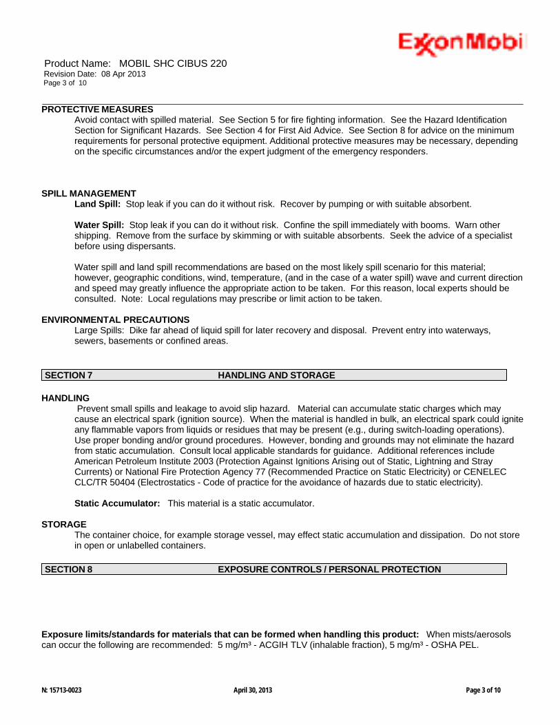
Product Name: MOBIL SHC CIBUS 220 Revision Date: 08 Apr 2013 Page 3 of 10
PROTECTIVE MEASURES Avoid contact with spilled material. See Section 5 for fire fighting information. See the Hazard Identification Section for Significant Hazards. See Section 4 for First Aid Advice. See Section 8 for advice on the minimum requirements for personal protective equipment. Additional protective measures may be necessary, depending on the specific circumstances and/or the expert judgment of the emergency responders.
SPILL MANAGEMENT Land Spill: Stop leak if you can do it without risk. Recover by pumping or with suitable absorbent.
Water Spill: Stop leak if you can do it without risk. Confine the spill immediately with booms. Warn other shipping. Remove from the surface by skimming or with suitable absorbents. Seek the advice of a specialist before using dispersants.
Water spill and land spill recommendations are based on the most likely spill scenario for this material; however, geographic conditions, wind, temperature, (and in the case of a water spill) wave and current direction and speed may greatly influence the appropriate action to be taken. For this reason, local experts should be consulted. Note: Local regulations may prescribe or limit action to be taken.
ENVIRONMENTAL PRECAUTIONS Large Spills: Dike far ahead of liquid spill for later recovery and disposal. Prevent entry into waterways, sewers, basements or confined areas.
HANDLING Prevent small spills and leakage to avoid slip hazard. Material can accumulate static charges which may cause an electrical spark (ignition source). When the material is handled in bulk, an electrical spark could ignite any flammable vapors from liquids or residues that may be present (e.g., during switch-loading operations). Use proper bonding and/or ground procedures. However, bonding and grounds may not eliminate the hazard from static accumulation. Consult local applicable standards for guidance. Additional references include American Petroleum Institute 2003 (Protection Against Ignitions Arising out of Static, Lightning and Stray Currents) or National Fire Protection Agency 77 (Recommended Practice on Static Electricity) or CENELEC CLC/TR 50404 (Electrostatics - Code of practice for the avoidance of hazards due to static electricity).
Static Accumulator: This material is a static accumulator.
STORAGE The container choice, for example storage vessel, may effect static accumulation and dissipation. Do not store in open or unlabelled containers.
Exposure limits/standards for materials that can be formed when handling this product: When mists/aerosols can occur the following are recommended: 5 mg/m³ - ACGIH TLV (inhalable fraction), 5 mg/m³ - OSHA PEL.
N: 15713-0023 April 30, 2013 Page 3 of 10
SECTION 8 EXPOSURE CONTROLS / PERSONAL PROTECTION
SECTION 7 HANDLING AND STORAGE
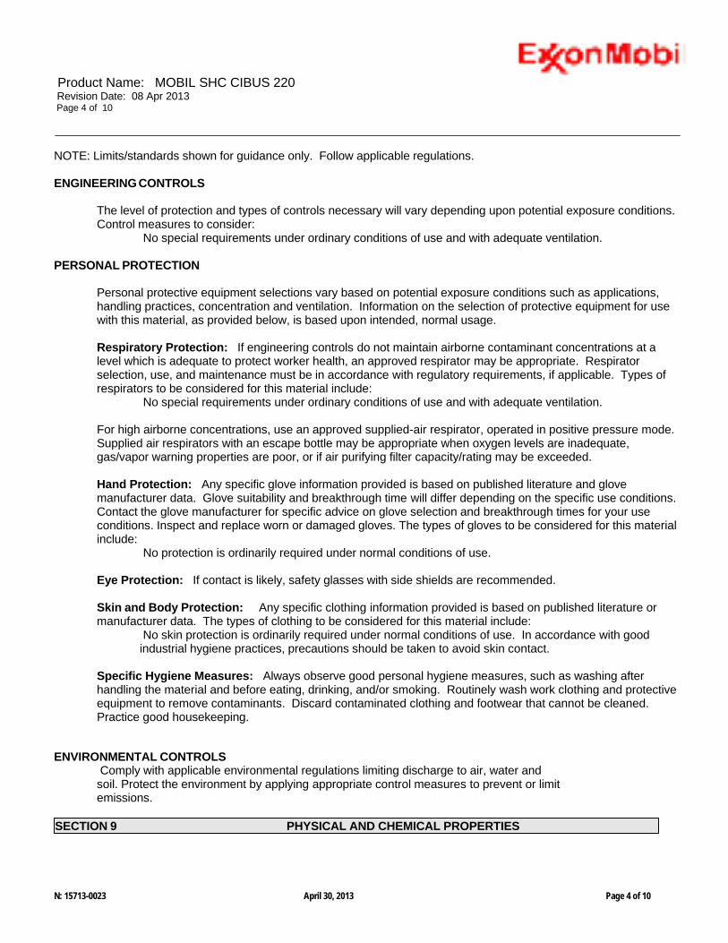
Product Name: MOBIL SHC CIBUS 220 Revision Date: 08 Apr 2013 Page 4 of 10
NOTE: Limits/standards shown for guidance only. Follow applicable regulations.
ENGINEERING CONTROLS
The level of protection and types of controls necessary will vary depending upon potential exposure conditions. Control measures to consider:
No special requirements under ordinary conditions of use and with adequate ventilation.
PERSONAL PROTECTION
Personal protective equipment selections vary based on potential exposure conditions such as applications, handling practices, concentration and ventilation. Information on the selection of protective equipment for use with this material, as provided below, is based upon intended, normal usage.
Respiratory Protection: If engineering controls do not maintain airborne contaminant concentrations at a level which is adequate to protect worker health, an approved respirator may be appropriate. Respirator selection, use, and maintenance must be in accordance with regulatory requirements, if applicable. Types of respirators to be considered for this material include:
No special requirements under ordinary conditions of use and with adequate ventilation.
For high airborne concentrations, use an approved supplied-air respirator, operated in positive pressure mode. Supplied air respirators with an escape bottle may be appropriate when oxygen levels are inadequate, gas/vapor warning properties are poor, or if air purifying filter capacity/rating may be exceeded.
Hand Protection: Any specific glove information provided is based on published literature and glove manufacturer data. Glove suitability and breakthrough time will differ depending on the specific use conditions. Contact the glove manufacturer for specific advice on glove selection and breakthrough times for your use conditions. Inspect and replace worn or damaged gloves. The types of gloves to be considered for this material include:
No protection is ordinarily required under normal conditions of use.
Eye Protection: If contact is likely, safety glasses with side shields are recommended.
Skin and Body Protection: Any specific clothing information provided is based on published literature or manufacturer data. The types of clothing to be considered for this material include:
No skin protection is ordinarily required under normal conditions of use. In accordance with good industrial hygiene practices, precautions should be taken to avoid skin contact.
Specific Hygiene Measures: Always observe good personal hygiene measures, such as washing after handling the material and before eating, drinking, and/or smoking. Routinely wash work clothing and protective equipment to remove contaminants. Discard contaminated clothing and footwear that cannot be cleaned. Practice good housekeeping.
ENVIRONMENTAL CONTROLS Comply with applicable environmental regulations limiting discharge to air, water and soil. Protect the environment by applying appropriate control measures to prevent or limit emissions.
N: 15713-0023 April 30, 2013 Page 4 of 10
SECTION 9 PHYSICAL AND CHEMICAL PROPERTIES

Product Name: MOBIL SHC CIBUS 220 Revision Date: 08 Apr 2013 Page 5 of 10
Note: Physical and chemical properties are provided for safety, health and environmental considerations only and may not fully represent product specifications. Contact the Supplier for additional information.
GENERAL INFORMATION Physical State: Liquid Color: Pale Yellow Odor: Characteristic Odor Threshold: N/D
IMPORTANT HEALTH, SAFETY, AND ENVIRONMENTAL INFORMATION Relative Density (at 15 °C): 0.857 Flash Point [Method]: >226°C (439°F) [ASTM D-92] Flammable Limits (Approximate volume % in air): LEL: 0.9 UEL: 7.0 Autoignition Temperature: N/D Boiling Point / Range: > 316°C (601°F) [Estimated] Vapor Density (Air = 1): > 2 at 101 kPa [Estimated] Vapor Pressure: < 0.013 kPa (0.1 mm Hg) at 20 °C [Estimated] Evaporation Rate (n-butyl acetate = 1): N/D pH: N/A Log Pow (n-Octanol/Water Partition Coefficient): > 3.5 [Estimated] Solubility in Water: Negligible Viscosity: >220 cSt (220 mm2/sec) at 40 °C | 24.5 cSt (24.5 mm2/sec) at 100°C Oxidizing Properties: See Hazards Identification Section.
OTHER INFORMATION Freezing Point: N/D Melting Point: N/A Pour Point: -18°C (0°F) Decomposition Temperature: N/D
STABILITY: Material is stable under normal conditions.
CONDITIONS TO AVOID: Excessive heat. High energy sources of ignition.
MATERIALS TO AVOID: Strong oxidizers
HAZARDOUS DECOMPOSITION PRODUCTS: Material does not decompose at ambient temperatures.
HAZARDOUS POLYMERIZATION: Will not occur.
ACUTE TOXICITY Route of Exposure Conclusion / Remarks
Inhalation Toxicity: No end point data for material. Minimally Toxic. Based on assessment of the components. Irritation: No end point data for material. Negligible hazard at ambient/normal handling temperatures.
Based on assessment of the components.
N: 15713-0023 April 30, 2013 Page 5 of 10
SECTION 11 TOXICOLOGICAL INFORMATION
SECTION 10 STABILITY AND REACTIVITY

Product Name: MOBIL SHC CIBUS 220 Revision Date: 08 Apr 2013 Page 6 of 10
Ingestion Toxicity: No end point data for material. Minimally Toxic. Based on assessment of the components.
Skin Toxicity: No end point data for material. Minimally Toxic. Based on assessment of the components. Irritation: No end point data for material. Negligible irritation to skin at ambient temperatures. Based on
assessment of the components.
Eye Irritation: No end point data for material. May cause mild, short-lasting discomfort to eyes. Based on
assessment of the components.
CHRONIC/OTHER EFFECTS For the product itself: Repeated and/or prolonged exposure may cause irritation to the skin, eyes, or respiratory tract.
Contains: Synthetic base oils: Not expected to cause significant health effects under conditions of normal use, based on laboratory studies with the same or similar materials. Not mutagenic or genotoxic. Not sensitizing in test animals and humans.
The following ingredients are cited on the lists below: None.
--REGULATORY LISTS SEARCHED-- 1 = NTP CARC 3 = IARC 1 5 = IARC 2B 2 = NTP SUS 4 = IARC 2A 6 = OSHA CARC
The information given is based on data available for the material, the components of the material, and similar materials.
ECOTOXICITY Material -- Not expected to be harmful to aquatic organisms.
MOBILITY Base oil component -- Low solubility and floats and is expected to migrate from water to the land. Expected to partition to sediment and wastewater solids.
Disposal recommendations based on material as supplied. Disposal must be in accordance with current applicable
N: 15713-0023 April 30, 2013 Page 6 of 10
SECTION 13 DISPOSAL CONSIDERATIONS
SECTION 12 ECOLOGICAL INFORMATION

Product Name: MOBIL SHC CIBUS 220 Revision Date: 08 Apr 2013 Page 7 of 10
laws and regulations, and material characteristics at time of disposal.
DISPOSAL RECOMMENDATIONS Product is suitable for burning in an enclosed controlled burner for fuel value or disposal by supervised incineration at very high temperatures to prevent formation of undesirable combustion products. Protect the environment. Dispose of used oil at designated sites. Minimize skin contact. Do not mix used oils with solvents, brake fluids or coolants.
REGULATORY DISPOSAL INFORMATION RCRA Information: The unused product, in our opinion, is not specifically listed by the EPA as a hazardous waste (40 CFR, Part 261D), nor is it formulated to contain materials which are listed as hazardous wastes. It does not exhibit the hazardous characteristics of ignitability, corrositivity or reactivity and is not formulated with contaminants as determined by the Toxicity Characteristic Leaching Procedure (TCLP). However, used product may be regulated.
Empty Container Warning Empty Container Warning (where applicable): Empty containers may contain residue and can be dangerous. Do not attempt to refill or clean containers without proper instructions. Empty drums should be completely drained and safely stored until appropriately reconditioned or disposed. Empty containers should be taken for recycling, recovery, or disposal through suitably qualified or licensed contractor and in accordance with governmental regulations. DO NOT PRESSURISE, CUT, WELD, BRAZE, SOLDER, DRILL, GRIND, OR EXPOSE SUCH CONTAINERS TO HEAT, FLAME, SPARKS, STATIC ELECTRICITY, OR OTHER SOURCES OF IGNITION. THEY MAY EXPLODE AND CAUSE INJURY OR DEATH.
LAND (DOT): Not Regulated for Land Transport
LAND (TDG): Not Regulated for Land Transport
SEA (IMDG): Not Regulated for Sea Transport according to IMDG-Code
AIR (IATA): Not Regulated for Air Transport
OSHA HAZARD COMMUNICATION STANDARD: When used for its intended purposes, this material is not classified as hazardous in accordance with OSHA 29 CFR 1910.1200.
Complies with the following national/regional chemical inventory requirements: AICS, DSL, IECSC, KECI, PICCS, TSCA
Special Cases:
Inventory StatusENCS Restrictions Apply
EPCRA SECTION 302: This material contains no extremely hazardous substances.
N: 15713-0023 April 30, 2013 Page 7 of 10
SECTION 15 REGULATORY INFORMATION
SECTION 14 TRANSPORT INFORMATION

Product Name: MOBIL SHC CIBUS 220 Revision Date: 08 Apr 2013 Page 8 of 10
NSF: H-1
SARA (311/312) REPORTABLE HAZARD CATEGORIES: None.
SARA (313) TOXIC RELEASE INVENTORY: This material contains no chemicals subject to the supplier notification requirements of the SARA 313 Toxic Release Program.
The following ingredients are cited on the lists below: None.
--REGULATORY LISTS SEARCHED-- 1 = ACGIH ALL 6 = TSCA 5a2 11 = CA P65 REPRO 16 = MN RTK 2 = ACGIH A1 7 = TSCA 5e 12 = CA RTK 17 = NJ RTK 3 = ACGIH A2 8 = TSCA 6 13 = IL RTK 18 = PA RTK 4 = OSHA Z 9 = TSCA 12b 14 = LA RTK 19 = RI RTK 5 = TSCA 4 10 = CA P65 CARC 15 = MI 293
Code key: CARC=Carcinogen; REPRO=Reproductive
N/D = Not determined, N/A = Not applicable
THIS SAFETY DATA SHEET CONTAINS THE FOLLOWING REVISIONS: Revision Changes: Section 04: First Aid Inhalation - Header was modified. Section 04: First Aid Ingestion - Header was modified. Section 06: Notification Procedures - Header was modified. Section 13: Disposal Considerations - Disposal Recommendations was modified. Section 09: Phys/Chem Properties Note was modified. Section 09: Color was modified. Section 09: Boiling Point C(F) was modified. Section 09: Pour Point C(F) was modified. Section 09: Evaporation Rate - Header was modified. Section 09: Flash Point C(F) was modified. Section 09: n-Octanol/Water Partition Coefficient was modified. Section 08: Personal Protection - Header was modified. Section 08: Comply with applicable regulations phrase was modified. Section 09: Vapor Pressure was modified. Section 07: Handling and Storage - Handling was modified. Section 07: Handling and Storage - Storage Phrases was modified. Hazard Identification: Health Hazards was modified. Section 11: Dermal Lethality Test Data was modified. Section 11: Dermal Lethality Test Comment was modified. Section 11: Oral Lethality Test Data was modified. Section 11: Inhalation Lethality Test Data was modified. Section 11: Dermal Irritation Test Data was modified.
N: 15713-0023 April 30, 2013 Page 8 of 10
SECTION 16 OTHER INFORMATION

Product Name: MOBIL SHC CIBUS 220 Revision Date: 08 Apr 2013 Page 9 of 10
Section 11: Eye Irritation Test Data was modified. Section 11: Oral Lethality Test Comment was modified. Section 11: Inhalation Lethality Test Comment was modified. Section 11: Dermal Irritation Test Comment was modified. Section 11: Eye Irritation Test Comment was modified. Section 11: Inhalation Irritation Test Data was modified. Section 05: Hazardous Combustion Products was modified. Section 09: Relative Density - Header was modified. Section 09: Flash Point C(F) was modified. Section 09: Viscosity was modified. Section 09: Viscosity was modified. Section 14: LAND (TDG) - Header was modified. Section 15: List Citation Table - Header was modified. Section 15: National Chemical Inventory Listing - Header was modified. Section 15: National Chemical Inventory Listing was modified. Section 15: Community RTK - Header was modified. Section 11: Additional Health Information was modified. Section 08: Exposure limits/standards was modified. Section 01: Company Contact Methods Sorted by Priority was modified. Section 06: Protective Measures was added. Section 06: Accidental Release - Protective Measures - Header was added. Section 15: Special Cases - Header was added. Section 15: Special Cases Table was added. Section 15: Inventory - Header was added. Section 15: Status - Header was added. Section 09: Decomposition Temperature was added. Section 09: Decomposition Temp - Header was added. Section 09: Vapor Pressure was added. Section 15: Chemical Name - Header was deleted. Section 15: CAS Number - Header was deleted. Section 15: List Citations - Header was deleted. Section 15: List Citations Table was deleted. ----------------------------------------------------------------------------------------------------------------------------------------------------- ----------------------------------------------------------------------------------------------------------------------------------------------------- The information and recommendations contained herein are, to the best of ExxonMobil's knowledge and belief, accurate and reliable as of the date issued. You can contact ExxonMobil to insure that this document is the most current available from ExxonMobil. The information and recommendations are offered for the user's consideration and examination. It is the user's responsibility to satisfy itself that the product is suitable for the intended use. If buyer repackages this product, it is the user's responsibility to insure proper health, safety and other necessary information is included with and/or on the container. Appropriate warnings and safe-handling procedures should be provided to handlers and users. Alteration of this document is strictly prohibited. Except to the extent required by law, re- publication or retransmission of this document, in whole or in part, is not permitted. The term, "ExxonMobil" is used for convenience, and may include any one or more of ExxonMobil Chemical Company, Exxon Mobil Corporation, or any affiliates in which they directly or indirectly hold any interest.
-----------------------------------------------------------------------------------------------------------------------------------------------------
Internal Use Only MHC: 0B, 0B, 0, 0, 0, 0 PPEC: A
DGN: 7091315XUS (1016025) -----------------------------------------------------------------------------------------------------------------------------------------------------
N: 15713-0023 April 30, 2013 Page 9 of 10

Product Name: MOBIL SHC CIBUS 220 Revision Date: 08 Apr 2013 Page 10 of 10
Copyright 2002 Exxon Mobil Corporation, All rights reserved
N: 15713-0023 April 30, 2013 Page 10 of 10