pfas remediation and disposal pfas...2019/07/07 · 1. presentations will be posted to...
TRANSCRIPT

EBC Emerging Contaminants Program:
PFAS Remediation and Disposal – PFAS
Detected, What’s Next?

Welcome
Daniel Moon
President & Executive Director
Environmental Business Council
Environmental Business Council of New England
Energy Environment Economy

Welcome
Blake Martin
Vice President
Weston & Sampson
Environmental Business Council of New England
Energy Environment Economy

Thank you to our Host

EBC Committees & Chapters
Environmental Business Council of New England
Energy Environment Economy
Climate Change and Air Committee
Dam Management Committee
Energy Resources Committee
Infrastructure Committee
Ocean and Coastal Resources Committee
Site Remediation and Redevelopment Committee
PCB & Emerging Contaminants Subcommittee
Solid Waste Management Committee
Water Resources Committee
Ascending Professionals Committee
Connecticut Chapter
New Hampshire Chapter
Rhode Island Chapter

EBC PCB & Emerging Contaminants
Subcommittee
Environmental Business Council of New England
Energy Environment Economy
Committee Chair
Frank Ricciardi, Weston & Sampson
Leadership Team
Malcolm Beeler, Weston & Sampson
Elizabeth Denly, TRC
Steven LaRosa, Weston & Sampson
Jim Occhialini, Alpha Analytical
Timothy Snay, Ransom Consulting

Programs
Access
Networking
EBC Membership Benefits
Environmental Business Council of New England
Energy Environment Economy

Upcoming Programs
Environmental Business Council of New England
Energy Environment Economy
July 26: New England Climate Change Summit
July 31: Treatment & Disposal of PCBs in Building Materials
Aug 1: Connecticut Program: PFAS Overview
Aug 6: Rhode Island Chapter Summer Gathering
Aug 8: 25th Annual Summer Garden Party
Sept 12: Annual Portsmouth, NH Harbor Cruise
Sept 17: Briefing from MassDEP Solid Waste Section Chiefs
Sept 20: Climate Adaptation Forum – Public Health
Sept 26: Connecticut Climate Change Update
Sept 27: Ocean Resources, Coastal Contamination

1. Presentations will be posted to “ebcne.org”– Link to location of presentations in follow-up email
2. Get involved in EBC Chapters and Committees– Join Leadership Teams
– Join Google Group for each committee / chapter
• Email request to [email protected]
3. Ask questions during presentations– Don’t hesitate to interrupt the speaker
4. Audience Introduction
Final Notes
Environmental Business Council of New England
Energy Environment Economy

Program Purpose – What You Will Learn
AnnieLu Dewitt
Program Co-Chair
PFAS Water Treatment Lead
Clean Harbors
Environmental Business Council of New England
Energy Environment Economy

11
11 July 25, 2019 - Clean Harbors Company Confidential
Introduction to the EBC PFAS Treatment and Disposal Program
EBC Program July 24th, 2019

12
What Questions Are We Hoping To Answer Today About the Current State of the PFAS Treatment and Disposal Field
• How did we get here?
• Where are we now?
• Where do we think this field is heading?
• What technologies are widely accepted for water and soil treatment and disposal?
• What are the developing technologies out there for managing PFAS impacted material?
• Review Case Studies of Ongoing Treatment projects
• Review the Lifecycle of a PFAS Water Treatment Project

13
How Did We Get Here
• UCMR 3 2012-2015 Public water supplies identified communities impacted by PFOA and PFOS
• Advances in Laboratory Testing- at the time of the UCMR 3 testing rounds the reporting limit was 200 ppt for a number of laboratories. By 2016 the industry standard dropped to 2-5 ppt and additional compounds were added to PFAS testing methods
• Public Awareness- NY, NH,VT and NC followed by MI in 2017.
• Flint, MI- “Flintification” states decided to get out in front of potential drinking water contamination issues

14
Federal Regulatory Status - PFAS
• June 27, 2019, the US Senate passed legislation to regulate per- and polyfluoroalkyl chemicals (PFAS) as a rider to the 2020 defense spending bill (S1790)
• Passed the House on July 12th,
• There appears to be gaps between house and senate bills on funding. The expectation
is that the states will continue to drive this process for the next one to two years.
• Manufacturers must list air and water PFAS discharges on TRI
• PFOA & PFOS managed under TSCA• With in 1 year EPA propose interim standards on
destruction and disposal • Expected that PFAS will be regulated as a hazardous
substance under CERCLA• EPA has established the health advisory levels at 70 parts
per trillion

15
State Regulatory Status - PFAS
• Many states are regulating PFAS more stringently than EPA has proposed
• MI,VT, NH, NJ, WI, MN, RI, MA, NC,MN and CA are all states that are rapidly going farther than then the federal guidelines
• States are moving to ranges of 10-20 ppt vs.70 ppt federally proposed
• NY State: Governor Cuomo has announced $350M to be available for drinking water projects

16 New EPA Method 8327 Compound list
• The new EPA PFAS testing method is finishing up it’s comment period. It is a direct injection method to address other matrixes besides drinking water. This new method will standardize methodologies and allow for better comparison of data between laboratories. Same LC/MS/MS instrumentation.
• PFBS PFBA
• PFPeS PFPeA
• PFHxS PFHxA
• PFHpS PFHpA
• PFOS PFOA
• PFNS PFNA
• PFDS PFDA
• 4:2 FTS PFUdA
• 6:2 FTS PFDoA
• 8:2 FTS PFTrDA

17 Where is the PFAS Treatment Field Heading
• How low can standards go? Just because we can does not mean we should. Going below 2 ppt is achievable. However, going lower opens up the possibility of detecting ambient levels of PFAS in the environment and potential laboratory background contamination calling results into question
• New technologies are being developed and the ones that can be made economically feasible and scalable will gain momentum

PFAS Water Treatment Lifecycle
AnnieLu DeWitt
PFAS Water Treatment Lead
Clean Harbors
Environmental Business Council of New England
Energy Environment Economy
19
19 July 25, 2019 - Clean Harbors Company Confidential
The Lifecycle of a PFAS Project

20
Terminology
PFAS Is a broad term used to encompass per-fluoroalkylsubstances and poly-fluoroalkyl substances. Please note that there are many synonyms for the same compounds. Nomenclature of organic chemistry is similar to dialects of the same language. Therefore, if possible you use CAS numbers to simplify the possible confusion of having different methods of nomenclature to reference the same analyte.
• Per-fluoroalkyl substances- subset of PFAS that describes fully substituted alkyl chains where fluorine replaces the hydrogen.
• Poly-fluoro alkyl substances- subset of PFASs that describes compounds where not all of the hydrogens have been substituted with fluorine.
• There are over 2000 known PFAS compounds. PFOA and PFOS are just two of the PFAS. The others until identified can be considered as “dark matter” possibly present but not qualified or quantified. Not an issue to qualify and quantify as but it is a matter of identifying.

21
PFAS Definition
PFAS are per and poly-fluorinated chained carbon compounds
They are used to make fabrics water-proofNon-stick cookwareAFFF (Aqueous Film Forming Foams)Popcorn BagsPost-It NotesCountless Manufacturing Processes

22
History of PFAS Production
• In 1938 at Dupont in Deepwater, NJ Teflon was created by accident in a failed refrigerant experiment. The waxy material produced proved to be the most slippery material in existence.
• 1951 Dupont makes C8 to make Teflon and related polymers at the Washington Works plant near Parkersburg, W. VA and by Minnesota Mining (3M)
• 1956 3M begins selling Scotchgard protector
• 1962 FDA approval for Teflon cookware
• 1967 FDA approval of Zonyl for use in food packaging

23 Commercial and Consumer Products containing PFAS
• paper and packaging
• clothing and carpets
• outdoor textiles and sporting equipment
• ski and snowboard waxes
• non-stick cookware
• cleaning agents and fabric softeners
• polishes and waxes, and latex paints
• pesticides and herbicides
• windshield wipers
• paints, varnishes, dyes, and inks
• adhesives
• medical products
• personal care products (for example, shampoo)

24
Where Are They Found
• DoD will be testing every base in the U.S. estimated to be over 600 sites (article in NY Times claims number is at 2000 now)
• Municipalities Drinking Water and Wastewater
• Landfills
• Airports
• Superfund Sites
• End-user Industrial Clients
• Plating Facilities
• Biosolids
• Fire Department Training Centers

25
Project LifeCycle Stages
• Identify- Characterize water with applicable test methods
• Pilot Study
• Define Project Objectives
• Select Best Fit Approach
• Choose Equipment
• O&M /Service System
• Final Deposition (landfill, reactivation, incineration)

26 Identification
• Analytical Lab Choice- experience is important. For example, multiple runs may be required to meet low detection levels if there are high concentrations for other PFAS compounds. 6:2 FTS dwarfing PFOS
• Choosing Appropriate Compound List- EPA Method 8327, DoD list, not all labs have GenX standards
• Currently modified 537 is not standardized across laboratories. The new EPA 8327 will create standardization between laboratories. The question now is when do you make the switch to the new method and how, do you run both methods for a period of time and what will the added cost be. For low flow systems analytical becomes a huge additional cost per gallon treated
• Test for other analytes that might interfere with adsorption and ion exchange. TOC, Fe, PO4, TDS
• TOP Assay- Total Oxidisable Precursor Assay analytical method helps to identify “dark matter” Good for initial influent water characterization

27 Examples of C8
Generic PFC structures. The 8-carbon (8C) structures are shown. The 8C, or "long-chain" structures are generally the most persistent.

28
Unidentified PFAS Compounds
• Unidentified PFAS compounds can be considered “dark matter” they consume media and shorten life expectancy of media
• Double-edged sword low detection limits means very selective identification
• Top Assay offers ability to gently oxidize and break compound down to base structures that can be measured. Not qualitative but helps with quantitation

29 Pilot Study
Once analytical is evaluated a pilot study demonstrates a scaled down version of a proposed full scale system. It also allows for evaluation of systems that have variability in influent over time. Especially useful in production facilities where influent varies between batches and processes. Pilot studies also allow for competitive adsorption to be identified and more accurate exchange rate estimations for media.

30
Define Project Objectives
• Most important stage
• Requires communication of limits to be achieved 2ppt, 70ppt for PFOA, PFOS combined, GenX, PFNA, combined list of compounds to not exceed 70 ppt
• Media requirements, Is GAC the only acceptable technology for a municipality
• Discharge permits, pH spikes from treatment
• Space Constraints sizing for 10 minute EBCT means big vessels

31
Select Best Fit Approach
• Balancing cost and performance
• Depending upon concentration and flow there will be a best fit solution
• For example, very low flow and high concentration may be best for straight incineration
• Very high concentration and high flow may be best for a resin application. Smaller vessels and higher capacity for media.
• Moderate concentrations and medium flow is where other considerations will sway which approach makes the best sense for a project. For example, remote location may dictate remote monitoring and high capacity media in a conex box.

32
Current Options for Treatment• GAC- Widely accepted treatment option for PFOA
and PFOS shorter chained PFAS compounds dictate very short exchange cycles
• Resin- Different resins are good options for longer chained compounds, PFOA, PFOS and for shorter chained PFAS that are poorly adsorbed by GAC. Shorter EBCT
• Oxidation and other destructive technologies- have shown effectiveness of breaking down longer chained compounds. Our hesitation is that with the complex influent water we see and rapid deployment we may not have time to do full studies to calculate required energy in a timely manner. A static system would be an ideal situation for this type of application
• Incineration of water
• Additives - Effective for reducing PFAS in highly concentrated waste streams
• Reverse Osmosis- Very effective with PFAS compounds but the reject stream can be substantial and skilled RO operators are in very demand
Emerging Contaminant Support Services

33 Choose Equipment
When choosing equipment for a project it is important to make the most of the available resources. Weighing rental and purchase decisions. Many times we have customers choose to rent equipment in the beginning for PFAS projects. There is hesitation to invest in a solution that may evolve with changing regulations. Guidance from states is increasingly lower reporting levels. VT, MI, NJ, CT, MA,RI, NH,NC,NY

34
O&M/ Service
• With PFAS projects analytical is an important part of the operation and maintenance program. Proper sampling, monitoring for breakthrough and performance confirmation
• Vessel swapping or on-site service. Remote locations can benefit from a vessel exchange program for lower flow applications
• Documentation of variables in system, flow, pH, pressure drop assist with optimizing treatment

35
Final Deposition of Media
• There are currently three options for media at the end of it’s lifecycle
• Landfill- many landfills are not accepting PFAS material.
• Reactivation- Investigate to make sure temperature is adequate to destroy the C-F bond
• Incineration- Is the current BDAT (best demonstrated available technology) destruction of media has been increasingly the choice for customers

36
Current CH Projects
• We have full scale current projects across the country that are in the ppt to ppm range consistently achieving ND levels (2-5 ppt)
• Piloting systems that evaluate difficult to treat systems to identify best pre-treatment and associated PFAS treatment.
• Every application is different and many times the pre-treatment requires more attention than the actual PFAS removal
• GAC and GAC/Resin solutions with associated pre-treatment. Concentrate contaminants onto media by adsorption and or ion exchange and then dispose of media
• Direct incineration of water and soil

37
Industrial Wastewater High Concentration PFAS Treatment
PFHxA
4:2 FTS0
10
20
30
40
Co
nc.
In P
PT
Date
Final
PFHxA PFHpA PFHpS PFOS
4:2 FTS 6:2 FTS PFOA
PFHxA
4:2 FTS0
200000
400000
600000
800000
10/16/2018
Co
nc.
in P
PT
Date
Raw Water
PFHxA PFHpA PFHpS PFOS
4:2 FTS 6:2 FTS PFOA
Industrial wastewater system with PFAS Concentrations as high as 700,000 ppt total PFAS consistently brought down to ND. Clean Harbors has designed and installed a system to treat 120 gpm daily. This treatment system has allowed customer to meet discharge parameters since installation.

38 Case Study – Petroleum Processing Client, Upper Midwest
PFAS Capture – Post-fire Construction and Operation of Treatment System
• System Design – Clean Harbors recommended the proper combination of equipment, filters, activated carbon, and resin needed to process PFAS concentrations. System is capable of flow rates up to 400 gallons per minute (gpm).
➢ Prior to mobilization, the system design was approved by the Wisconsin Department of Natural Resources (WDNR) to levels suitable for discharge to the environment.
• System Construction – The entire system was transported, then constructed on-site in less than 3 days. After one day of performance testing, the system successfully reduced PFAS concentrations to non-detectable levels. System operates at 250 gpm.
➢ PFAS concentrations in the discharge water are well below permit limits. A second, similar system was installed on a similar schedule six weeks later.
• System Operation & Maintenance – Clean Harbors was contracted to operate the system to properly balance the treatment system alongside the on-site wastewater treatment plant operations. Clean Harbors then trained client personnel. Client staff assumed responsibility for system operation several weeks later.
➢ Clean Harbors continues media change-out and disposal services, including incineration and hazardous landfilling.
Subcontract Remediation Services

39
Case Study – Industrial Plater, Michigan
PFAS Control – Emergency; Full Scale Treatment Design and Implementation
Clean Harbors was contracted by a Michigan plating and surface finishing firm after discovery of multiple PFAS compounds in its discharge to the local publically owned treatment works. The POTW set strict PFAS limits, and demanded compliance within a limited time or cessation of all discharges. Clean Harbors provided services that met its client’s discharge permit limits, allowing continued operations.
• Operations analysis – Fluctuations in product demand triggered irregular treatment, discharge, and renewal of individual baths, which yielded a waste stream of constantly changing chemical composition.
• Media testing – Clean Harbors tested a number of adsorbent media, individually and in series. Each was intended to adsorb PFAS compounds or inorganic and organic waste components that interfered with PFAS capture.
• Full-scale system design – Testing data and the extensive experience and expertise of Clean Harbors staff were used to develop a treatment system.
• System installation and operation – Clean Harbors constructed and started the treatment system, which met POTW permit limits before the deadline. Clean Harbors commenced support of client staff through media exchange and disposal services, as well as performance testing.
Subcontract Remediation Services

PFAS Contaminated Soils Washing
Adrian Convery
Landfill Diversion Sector Manager
CDEnviro
Environmental Business Council of New England
Energy Environment Economy

CDEnviro – PFAS Contaminated Soils Washing
24th July 2019

Contents
- Background of CDEnviro- Installation Locations- PFAS Contaminated Soils Washing- Water Treatment- USA Project Examples

CDEnviro Background Info
- CDEnviro is a company within the CDE Group, formed in 1992 and employing over 400 people across 8 regions.
- We develop bespoke processing systems for a variety of wastes to recycle wastes to resources.
- USA offices are located in Cary, North Carolina and Cleburne, Texas.
- Waste Recycling- Contaminated Soils- Construction and Demolition- Dredged Sediment- Street Sweepings- MRF Glass Waste- Food Waste
- Waste Water Recycling- Sludge Screening- Anaerobic Digester Cleaning

Installations

Scrubbing and Attrition
Hydro:Grade
Attrition Cells
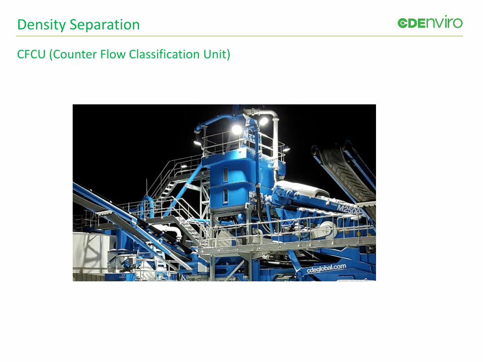
Density Separation
CFCU (Counter Flow Classification Unit)

Water Treatment
- Stage 1 – Advanced Filtration System to effectively reduce solids under 25 micron in wash water using filtration media.
- Stage 2 – Removing dissolved organic contaminants and hydrocarbons from water via adsorption.
- Stage 3 – Heavy metal reduction using Ion Resin Exchange.- Stage 4 – Disinfection to remove harmful bacteria using hypochlorite based
chemicals.
- Four Stage Solution for Advanced Water Treatment

USA Project Examples
Metroplex Sand & Gravel, Texas
The final products include Concrete Sand, Asphalt Sand, Masonry Sand, Cushion Sand, Concrete Rock and Pea Gravel.Client required Modularity – Plant was moved north to a new location after 1.5 years at the original site.
4 weeks for breakdown, 4 weeks to reinstall.
Matthews Sand & Gravel, North Carolina
This modular plant is offering feeding, screening, sand washing, stockpiling on a compact chassis which allowed the producer to nearly triple production levels. The final products include concrete sand and a residual fine sand.

USA Project Examples
Martin Marietta, Burlington Quarry, North Carolina
Fines recovery unit. This machine recovers virtually all sand larger than #325 sieve which overflows the sand screw.Currently this unit recovers 5-10 tph of sand which previously went to the settling ponds. Now, only the #325 sieve minus reports to the settling ponds, resulting in dramatically less pond maintenance and costs.
GS Materials, North Carolina
Specialist golf sands produced.

QUESTIONS AND DISCUSSION

PFAS Treatment in Soil and Water
Lauren Soós
Project Manager
Operations & Technical Sales
TRS Group, Inc.
Environmental Business Council of New England
Energy Environment Economy

July 24, 2019
PFAS Treatment in Soil and WaterIn Situ Thermal Remediation for Soils
PerfluorAd for Water
Lauren Soós
TRS Group
978-514-3133

Who are TRS and Cornelsen?
• 100% ESOP
• Health & Safety
• Best Practices
• Technologies
• Joint Ventures
• 220 ISTR Projects
• R&D

Why ISTR: The Results
99.995% removal
Guaranteed
Vadose zone
Saturated zone
Silty clay
Strip Mall in Alexandria, Virginia

ISTR Technology Comparison
Electrical Resistance Heating
Thermal Conduction Heating
Steam Enhanced Extraction
High Temperature TCH
ERH HEPA® Remediation
RDX/DPCA* TCE PCE Xylenes Napthalene PCB Dioxin PFAS
100 °C 200 °C 300+ °C Boiling Point
50 °C
*DPCA: Dissolved Phase Chlorinated Alkenes

FlexHeater® Remediation Service
• Patent awarded Feb. 2019
• Infra-red radiation
• Variable heating
• Small diameter casing

FlexHeater® Element
59

PFAS Remediation in Soil
FlexHeater® technology
• Vadose zone soils
• Ex situ cells

Proof of ConceptTreatment of PFAS in Soil

Ex Situ Cell Heat Up

PFAS Thermal Treatment System

PFAS Volatilization from SoilTime & Temperature
0
5,000
10,000
15,000
20,000
25,000
Unheated300 °C
350 °C400 °C
PFA
S So
il C
on
cen
trat
ion
(µ
g/kg
)
350°C: 99.91% reduction
400°C: 99.998% reduction
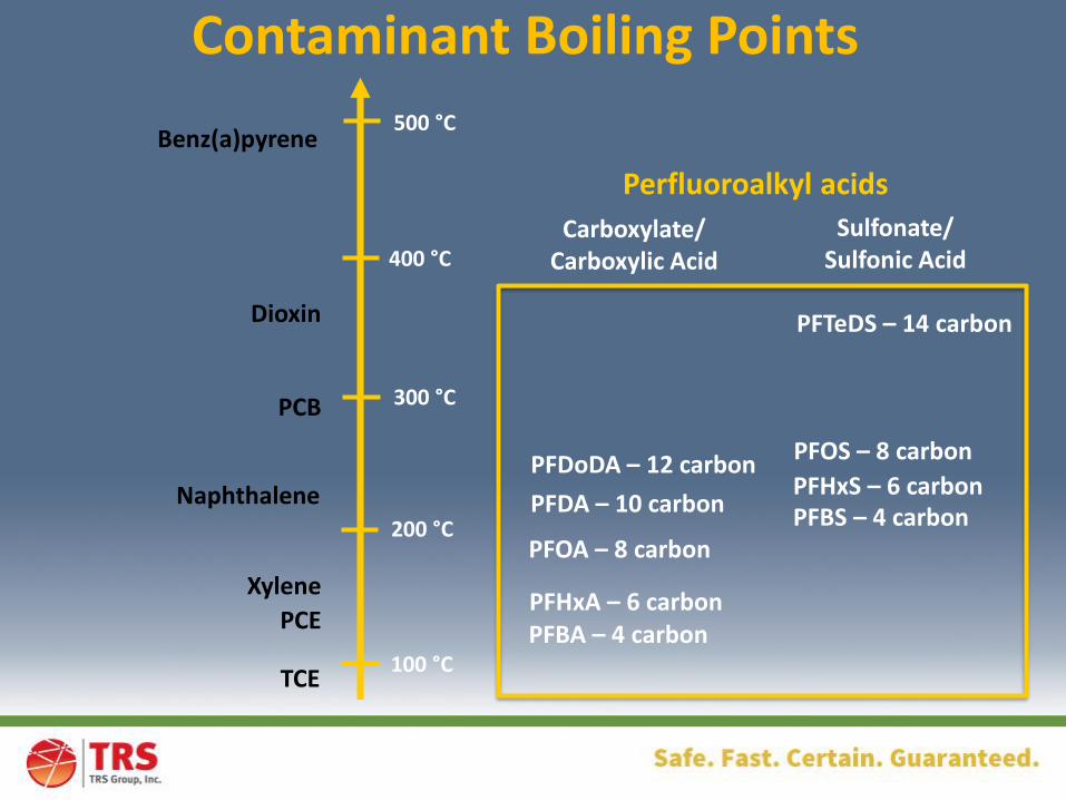
Contaminant Boiling Points
100 °C
200 °C
300 °C
400 °C
500 °C
TCE
PCE
Xylene
Naphthalene
PCB
Dioxin
Benz(a)pyrene
Sulfonate/Sulfonic Acid
PFTeDS – 14 carbon
PFOS – 8 carbon
PFHxS – 6 carbonPFBS – 4 carbon
PFBA – 4 carbonPFHxA – 6 carbon
PFOA – 8 carbon
PFDA – 10 carbon
PFDoDA – 12 carbon
Carboxylate/Carboxylic Acid
Perfluoroalkyl acids

Next Steps
✓ Substantial PFAS reductions in bench tests
✓ Temperatures achievable by FlexHeater® technology
• Field demonstration

Treating PFAS in Water with thePerfluorAd System

PFAS Water Treatment - PerfluorAd
• Treatment system – GAC or ion exchange polish
• Plant-based oleic acid
• Forms ionic bond w/PFAS
• Works with high DOC
• Rapid return on investment
© Cornelsen Umwelttechnologie GmbH
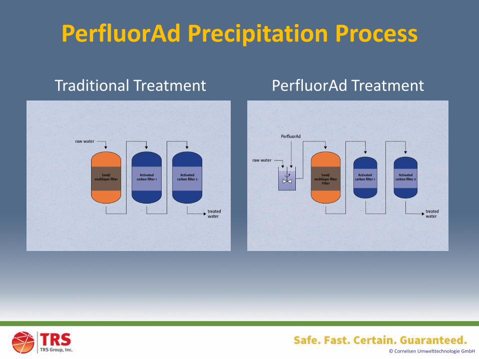
PerfluorAd Precipitation Process
Traditional Treatment PerfluorAd Treatment

© Cornelsen Umwelttechnologie GmbH
PerfluorAd Advantage

Courtesy of CDM Smith and Colorado School of Mines
Wurtsmith AFB Groundwater

© Cornelsen Umwelttechnologie GmbH
PFAS in Fire Water

Nuremberg Airport Fire Brigade Training Area
© Cornelsen Umwelttechnologie GmbH

© Cornelsen Umwelttechnologie GmbH
93.5 % Removal
100 % Removal
Nuremberg Airport Fire Brigade Training Area
ND

Conclusions
• ISTR
– VOCs, SVOCs, PCBs, 1,4-Dioxane
– PFAS in soil
• PerfluorAd system
– PFAS in water
– Fire water
– Landfill leachate


Networking Break
PFAS Treatment & Disposal
Solutions
Hugo DelRosso
Senior Account Executive
US Ecology
Environmental Business Council of New England
Energy Environment Economy

92
July 24, 2019
PFAS Treatment &
Disposal Solutions

9393
• TSCA PCB’s
• RCRA Metals
• RCRA Organics
• RCRA Listed Waste
• NORM/TNORM
Mixed Waste Treatment/Disposal
▪ Secure Subtitle C Landfill
▪ Treatment Facilities
▪ Treatment options for high/low
concentrations
▪ Isolation of treated residuals from leachate
▪ Rail and Truck Access
Waste Type Considerations
• AFFF Concentrate
• Impacted Soil
• Impacted WWT Media
• WWT Filtercake
• Impacted Debris
US Ecology PFAS Treatment & Disposal

9494
Beatty, Nevada
• Michigan (Belleville)
• Quebec (Blainville)
• Idaho (Grandview)
• Nevada (Beatty)
• Texas (Robstown)
Subtitle C Landfill
▪ Positioned throughout North America
▪ Treatment & Disposal Facilities
▪ Broad Range of Permits/Acceptance Criteria
▪ Infrastructure to Support Volume Transport
▪ Rail and Truck Access
▪ Non-Bulk T&D Services Available
Grand View, Idaho
US Ecology Disposal Options
Deep Well
• Winne, TX
Incineration
• Robstown, TX
• Saint Ambrose, QC

95
Batch Solidification
Leak-Proof Pactec Liner (high concentrations)
Placement in Subtitle C Landfill
Isolated from Leachate
US Ecology Michigan (WDI/MDI)

96
Native Clay
Peastone - minimum 24”
Hazardous Waste
5 ft. Re-compacted Clay
80 mil. HDPE Primary Liner
60 mil. HDPE Secondary Liner
Leachate
Detection
System
Leachate
Primary
Collection
System 6” Top Soil
Minimum 3 ft. Final Clay Cover
1 ft. Sand
30 mil. HDPE Cover Liner
1 ft. Clay
Intermediate Cover
Grass
Wayne Disposal, Inc.
Subtitle “C” Landfill

97
US Ecology Texas
Robstown, TX Thermal
Process & Recycle numerous waste streams
• “PFAS” Streams
• Organic-bearing waste from petroleum,
petrochemical, ethylene processing
and other manufacturing practices
• Organic liquids, sludges and solids
• Metal-bearing catalysts
• RCRA Listed (K171 and K172) catalyst
• RCRA exempted metal-bearing catalyst
Incineration

• F.K.A. Récupère Sol
• High Temp Soil Incineration
• 99.99999% Destruction of Organic Contaminants
• Controlled-emission soilcooling system
• Continuous monitoring of stack gas emissions
• Treatment of industrialwastewater
• Secure site
RSI

99
Landfills
Treatment
Treatment & Disposal Locations
Deep Well
Incineration


Thermal Desorption PFAS
Contaminated Soils
Scott Miller
Regional General Manager
Clean Earth
Environmental Business Council of New England
Energy Environment Economy

EBC MassachusettsThermal Desorption PFAS Contaminated Soils

Thermal Desorption PFAS SoilPresentation Summary1. Who is Clean Earth?
2. Thermal Desorption Overview
3. Fort Edward Initial RD&D
4. Fort Edward Proposed Second RD&D

Recently Acquired
by:
HARSCO Corporation
Our network of full-servicetreatment, disposal, andrecycling locations provides the bestsolutions for our customers.
27Facilities Nationwide

About Clean EarthTreatment & Recycling Facts
ENGINEERING NEWS-RECORD
TOP 200ENVIRONMNETAL FIRMS
2018
of the material
we process is
recycled
3.6
Million
8.8
Million
OV
ER
of the material we
process is recycled
4 Milliontons recycled
in 2018
8 Million
7 Millionyd3 dredged material
recycled since 1996
pounds of aerosol
products recycled in
2018
25reclaimed industrial
brownfields & former
landfills
OV
ER
OV
ER
OV
ER
ENGINEERING NEWS-RECORD
TOP 600SPECIALTY CONTRACTORS
2018
ENGINEERING NEWS-RECORD
NO. 9TOP 30 ENVIRONMNETAL FIRMS
2018
ENGINEERING NEWS-RECORD
NO.7TOP ENVIRONMNETAL MGMT FIRMS
2018

Thermal Treatment OptionsFacilities in New England
1. Clean Earth Loudon (ESMI NH)67 International Drive, Loudon, NH 03307
Main: 603-783-0228
2. Clean Earth Fort Edward (ESMI NY)304 Towpath Lane, Fort Edward, NY 12828
Main: 518-747-5500
3. Clean Earth Plainville (Phoenix Soil)58 North Washington Street, Plainville, CT 06062
Main: 860-747-8888
4. Clean Earth Mobile ServicesOn Site Low Temperature Thermal Desorption (LTTD) units

Thermal Treatment Operating Principles
What is Low Temperature Thermal Desorption (LTTD)?• < 1,000 oF (>1,000 oF = incineration)
Utilizes heat to physically separate contaminates from soil• Rotary Kiln (volatilization and steam stripping)• Volatilization (temperature ranges from 550-900 oF)
Contaminants in gas stream are thermally oxidized• Thermal oxidation (range from 1,500-2250 oF)• Immediate quench of gas stream (to 420oF)• Bag house (particulate removal)• Effluent stack (CECT equipped with wet scrubber)
*Effluent stack discharges less emissions than your car

Thermal Treatment Process Diagram

Clean Earth Fort Edward Initial RD&D
PFAS Thermal Treatment Demonstration• New York State Department of Environmental Conservation (NYSDEC)
Led PFAS Treatment Test• 22.6 Tons Treated in December 2018 & February 2019• High Soil Organic Matter (SOM) at over 7%• PTU Temperature 910-940 oF, STU Temperature 1800 oF• Treatment Goal of 72 ppb for total of PFOA and PFOS• No stack testing due to small sample size

Pre & Post Primary and Secondary Treatment for Total Mass (ug/kg)
Substance
Pre-Primary
Treatment (ppb)
Post-Primary
Treatment (ppb)
Post-Primary
Removal Efficiency
Post-Secondary
Treatment (ppb)
Post-Secondary
Removal Efficiency
Perfluorobutanoic acid (PFBA) 0.42 ND 100% ND 100%
Perfluoropentanoic acid (PFPeA) 0.63 ND 100% ND 100%
Perfluorohexanoic acid (PFHxA) 0.70 ND 100% ND 100%
Perfluoroheptanoic acid (PFHpA) 1.10 ND 100% ND 100%
Perfluorooctanoic acid (PFOA) 4.50 ND 100% ND 100%
Perfluorononanoic acid (PFNA) 2.90 ND 100% ND 100%
Perfluorodecanoic acid (PFDA) 5.70 ND 100% ND 100%
Perfluoroundecanoic acid (PFUnA) 3.00 ND 100% ND 100%
Perfluorododecanoic acid (PFDoA) 2.20 ND 100% ND 100%
Perfluorotridecanoic acid (PFTriA) 0.94 ND 100% ND 100%
Perfluorotetradecanoic acid (PFTeA) 0.88 ND 100% ND 100%
Perfluorobutanesulfonic acid (PFBS) 0.09 ND 100% ND 100%
Perfluorohexanesulfonic acid (PFHxS) 0.24 0.05 78.1% ND 100%
Perfluoroheptanesulfonic acid (PFHpS) 0.55 0.05 90.3% ND 100%
Perfluorooctanesulfonic acid (PFOS) 88.00 7.65 91.3% ND 100%
Perfluorononanesulfonic acid (PFNS) 0.04 ND 100% ND 100%
Perfluorodecanesulfonic acid (PFDS) 0.13 ND 100% ND 100%
Perfluorooctanesulfonamide (FOSA) 1.15 ND 100% ND 100%
(NMeFOSAA) 3.35 ND 100% ND 100%
(NEtFOSAA) 6.40 ND 100% ND 100%
Total PFAS 122.91 7.76 93.7% ND 100%

Pre & Post Primary and Secondary Treatment by SPLP (ng/kg)
Substance
Pre-Primary
Treatment
(ppt)
Post-Primary
Treatment (ppt)
Post-Primary Removal
Efficiency
Post-Secondary
Treatment (ppt)
Post-Secondary
Removal
Efficiency
Perfluorobutanoic acid (PFBA) 29.38 ND 100% ND 100%
Perfluoropentanoic acid (PFPeA) 15.30 ND 100% ND 100%
Perfluorohexanoic acid (PFHxA) 10.85 ND 100% ND 100%
Perfluoroheptanoic acid (PFHpA) 14.50 ND 100% ND 100%
Perfluorooctanoic acid (PFOA) 109.50 0.44 99.6% ND 100%
Perfluorononanoic acid (PFNA) 68.00 ND 100% ND 100%
Perfluorodecanoic acid (PFDA) 18.80 ND 100% ND 100%
Perfluoroundecanoic acid (PFUnA) 1.40 ND 100% ND 100%
Perfluorododecanoic acid (PFDoA) 0.65 ND 100% ND 100%
Perfluorotridecanoic acid (PFTriA) ND ND N/A ND N/A
Perfluorotetradecanoic acid (PFTeA) 0.57 ND 100% ND 100%
Perfluorobutanesulfonic acid (PFBS) ND 0.44 N/A ND N/A
Perfluorohexanesulfonic acid (PFHxS) 3.65 0.60 83.5% ND 100%
Perfluoroheptanesulfonic acid (PFHpS) 7.28 0.47 93.5% ND 100%
Perfluorooctanesulfonic acid (PFOS) 527.50 20.50 96.1% ND 100%
Perfluorononanesulfonic acid (PFNS) ND ND N/A ND N/A
Perfluorodecanesulfonic acid (PFDS) ND ND N/A ND N/A
Perfluorooctanesulfonamide (FOSA) ND ND N/A ND N/A
(NMeFOSAA) ND ND N/A ND N/A
(NEtFOSAA) ND ND N/A ND N/A
Total PFAS 807.37 22.45 97.2% ND 100%

Clean Earth Fort Edward Second RD&D
Second RD&D Objectives• Measure stack emissions (MM5) for the presence of PFAS compounds• Demonstrate compliance with soil clean-up objectives for reuse• Use performance data to determine LTTD removal/destruction
efficiency and effectiveness for processing PFAS contaminated soil
Second RD&D proposed for Q4 2019

Clean Earth Fort Edward Second RD&D
Proposed PFAS Thermal Treatment Demonstration• NYSDEC Led – Second RD&D Submitted and reviewed June/July• Three separate batches (control and 2 confirmed PFAS)• Varying STU temperatures per batch (1800 oF and 1500 oF)• Pre/post treatment sample collection & analysis (mass & SPLP)• Treatment Goal of 72 ug/kg for total of PFOA and PFOS, 10 ppt each by SPLP• Emission samples to be collected and analyzed per Modified Method 5
(MM5)• 21-Compound PFAS List soil and stack emissions

Modified Method 5 Testing Diagram

PFAS Contaminated SoilTreatment Options in Development
1. Additional Thermal Treatment Options• Similar demonstrations with stack emission testing for
facilities in Loudon, NH and Plainville, CT
• Mobile LTTD demonstration
2. Solidification/Stabilization• Encapsulating or binding PFAS compounds within the soil
matrix reducing mobility
• Treatability studies using proprietary blends of Portland cement, carbon and CKD for in-situ and ex-situ treatment alternatives

Contact Me with Questions
Scott A. Miller, P.E.
Regional General Manager, New England
Clean Earth
58 North Washington Street, Plainville, CT 06062
T 860.747.8888 x 2004 | C 860.670.7608
[email protected] | www.cleanearthinc.com
Questions?

PFAS/PFOS Waste Management
Options, Best Practices and
Challenges
Phillip Retallick
Senior Vice President
Compliance and Regulatory Affairs
Clean Harbors
Environmental Business Council of New England
Energy Environment Economy

“PFAS/PFOS Waste Management Options,
Best Practices and Challenges”
Presented Before
Environmental Business Council of New England
July 24, 2019

119July 25, 2019 - Clean Harbors Company Confidential
Introduction to Clean Harbors
• Founded in 1980
• Publicly Traded Corporation
(NYSE: CLH)
• Over $3.2 Billion USD in Revenue in
2015
• North America’s Largest Hazardous
Waste Disposal Company
• Leading Provider of Comprehensive
Environmental, Energy and Industrial
Services
• Largest used oil collector and re-
refiner in North America

120July 25, 2019 - Clean Harbors Company Confidential
Company Profile
• More than 260,000 customers
including a majority of the Fortune
500
• More than 13,000 employees
in over 350 service locations
in US, Canada, Mexico and
Puerto Rico
• Over 50 waste management
facilities
• Expanded North American
footprint with our Safety-Kleen
branch network

121July 25, 2019 - Clean Harbors Company Confidential
Risk & Security Management
• Health & Safety is Clean Harbors' #1 Priority– TRIR 1.33 in 2015 – DART .83 in 2015– EMR 0.67 in 2015– OSHA Voluntary Protection Program (VPP) at Clean Harbors
Facilities
• Regulatory Compliance– Encompasses All Clean Harbors Activities– Clean Compliance Program
• Liability Protection– Comprehensive General Liability– Umbrella Liability– Workers’ Compensation and Employers’ Liability– Contractors’ Pollution Liability– Environmental Impairment Liability

122July 25, 2019 - Clean Harbors Company Confidential
Complementary Networks
Clean Harbors Footprint Safety-Kleen Footprint

123July 25, 2019 - Clean Harbors Company Confidential
Asset Infrastructure
• 3 Solvent Recycling Facilities– Recycling, tolling and chemical sales
• 6 Incineration Facilities (9 Incinerators)– Greatest commercial hazardous waste incineration
capacity in North America
– Thermal treatment of liquid and solid hazardous wastes
• 9 Landfills– Hazardous and non-hazardous waste disposal capabilities
– More than 25 million cubic yards of remaining capacity
• 7 Wastewater Treatment Operations– Treatment of hazardous and non-hazardous wastes
received in liquid and sludge form
• 22 Treatment Storage & Disposal Facilities (TSDF)– Provides broad coverage across North America
• 6 PCB Management Facilities– Recycling and disposal
• 4 Oil & Used Oil Products Recycling Facilities

124July 25, 2019 - Clean Harbors Company Confidential
Management of PFAS As-Generated and
Site Remediation Waste
• Management of PFAS waste is a very challenging task
given the diverse isomeric chemistry of these substances
coupled with their tendency to be persistent in the
environment;
• There is little regulatory agency guidance available today to
help select the best demonstrated treatment waste
technology given the ubiquitous nature of PFAS
contamination in the environment;
• Selection of Waste Treatment Technologies must also
account for potential of cross-media transfer of treatment
residues into the ecosystem.

125July 25, 2019 - Clean Harbors Company Confidential
Management of As-Generated PFOS/PFAS
Wastes such as Firefighting Foam Products
• The Best Demonstrated Available Technology (BDAT) available today to destroy stockpiles of Firefighting Foam Products is High-Temperature Incineration with Acid Gas Scrubbing and Particulate Removal Technology;
• The US DOD mandates utilization of High Temperature Incineration Technology to destroy As-Generated and Remediation Wastes;
• The Interstate Technology Regulatory Council (ITRC) recommends Disposal of expired or unneeded Class B fluorinated foam concentrate at a Resource Conservation and Recovery Act (RCRA) permitted incinerator or another alternative incinerator that can ensure complete destruction of the PFAS; (note 1)
• Emerging technologies such as Supercritical Water Molecular Disassociation Chemistry, ReDOX Chemistry and Molecular Substitution Chemistry are not ready for commercialization, especially for destruction of Firefighting Foam stockpiles.
– Note 1: See Remediation Technologies and Methods for Per- and the Interstate Polyfluoroalkyl Substances (PFAS) fact sheet for details on
– thermal destruction of PFAS (ITRC 2018).

126July 25, 2019 - Clean Harbors Company Confidential
Management of PFAS Contaminated Media &
Remediation Wastes
• PFAS contamination in soil, river sediment, surface water and
groundwater creates unique challenges for the responsible party that
must select the appropriate technology to address contamination in a
cost-effective yet environmentally sound manner:
• Aside from High Temperature Incineration other commercially
demonstratable technologies include:
– GAC/PAC Carbon Sorption and Stabilization
– Isolation via containment capping of contaminated area requiring long term O&M
– Excavation and Disposal via Landfill or High Temperature Incineration
– Thermal Desorption provided the TDU is connected to an Incinerator that achieves at least 99.99 % Destruction and Removal Efficiency “DRE”, and the desorbed organics are incinerated in a RCRA High-Temperature Incinerator that achieves 99.99% - Plus DRE.

127July 25, 2019 - Clean Harbors Company Confidential
Interstate Technology Regulatory Council “ITRC” PFOs and
PFAs Waste Treatment Technology Analysis and
Recommendations

128July 25, 2019 - Clean Harbors Company Confidential
Landfill Network• Landfills
– Hazardous and non-hazardous waste disposal capabilities
– More than 25 million cubic yards of remaining capacity
– Leachate collected and treated to prevent subsequent discharges of PFAS - laden Leachate to Groundwater and Surface Water.
• Landfills Accepting PFAS Waste Streams
– Sarnia (CDN), Lone Mountain, Grassy Mountain, Deer Trail, Ryley (CDN)
– Rail served

129July 25, 2019 - Clean Harbors Company Confidential
Landfill Construction
Deer Trails Subtitle C Disposal Cells –
constructed and operated to meet or
exceed State and Federal Regulations.
-Naturally low-permeable sediments - clay soil & Pierre
weathered shale
-Primary & Secondary synthetic HDPE liner systems
-Dual leachate detection/collection system

130July 25, 2019 - Clean Harbors Company Confidential
Deer Trail - Geology

131July 25, 2019 - Clean Harbors Company Confidential
PFAS Soil
Transportation and
Disposal
• Manage transportation
and disposal from IDW
drums to unit trains of
soil
• Own our rail cars and
intermodal containers

132July 25, 2019 - Clean Harbors Company Confidential
High Temperature Incineration
Technology Overview
• High Temperature Incineration Technology (HTI) has been employed
since the 1960’s to effectively destroy simple and complex organic
waste streams, including the Halogen Series Compounds e.g. PCBs,
CFCs, Brominated Compounds;
• HTI Technology consists of the following elements:
– Primary Combustion Chamber (1500-1800o F)
– Secondary Combustion Chamber (1800-2050o F)
– Spray Dryer
– Acid Gas Scrubbing Technology to neutralize HCL, H2SO4 and HF Acid vapors
– Particulate Filtration ( primarily two-stage baghouse configuration)
– DE NOx Removal
– Polishing Carbon Filtration to remove Dioxins and Mercury

133July 25, 2019 - Clean Harbors Company Confidential
High Temperature Incineration Principles
• Optimized Incineration of Hazardous Waste is governed by the following parameters:
– Consistent High Temperature Regimes in primary and secondary combustion chambers;
– Sufficient Solids and Vapors Retention Time in the Combustion Zone (from Seconds for vapors to hours for solids);
– Flame Zone Turbulence (governed by Burner Design);
– We Refer to “The 3- T’s” when determining Optimization through USEPA and State Regulatory Agency mandated Compliance Performance Tests (CPTs) conducted during Real-Time Waste Destruction Activities;
– The CPT’s generate Destruction and Removal Efficiencies (DREs) which show the incineration train’s ability to destroy complex organic compounds, like PFAS, plus remove inorganic heavy metals regulated under the MACT Standards;
– DREs are expressed as 99.99 to 99.9999+ %

134July 25, 2019 - Clean Harbors Company Confidential
Clean Harbors Incineration Technology
Capabilities
• Clean Harbors Incinerator Locations:
– Deer Park, Texas
– El Dorado Arkansas
– Aragonite, Utah
– Kimball, Nebraska
– Sarnia, Ontario Province, Canada ( includes a TDU which is directly connected to the on-site commercial high temperature incinerator which destroys all exhaust vapor and condensate ).
Total Annualized Incineration Capacity = 800,000 metric tons/yr.

135July 25, 2019 - Clean Harbors Company Confidential
Highlighting Clean Harbors Newest High
Temperature Incineration Train in El Dorado,
Arkansas
• The El Dorado Incineration Complex added a new
incineration train meeting the latest USEPA MACT EEE
emissions standards in December, 2016;
• The new unit can manage bulk and containerized solid
and liquid waste streams and has the capability to
directly feed liquids and gases from shipping
containers into the primary and secondary combustion
chambers;
• The new incinerator train increased site capacity from
73,000 metric tons/yr. to 140,000 metric tons/yr.

136July 25, 2019 - Clean Harbors Company Confidential
Highlighting Clean Harbors Newest High
Temperature Incineration Train in Eldorado,
Arkansas

137July 25, 2019 - Clean Harbors Company Confidential
Highlighting Clean Harbors Newest High
Temperature Incineration Train in El Dorado,
Arkansas

138July 25, 2019 - Clean Harbors Company Confidential
1 - Rotary kiln and secondary combustion chamber.

139July 25, 2019 - Clean Harbors Company Confidential
2 - Spray dryer.

140July 25, 2019 - Clean Harbors Company Confidential
3 - First baghouse and wet scrubbers.

141July 25, 2019 - Clean Harbors Company Confidential
4 - Second baghouse and Carbon
Injection

142July 25, 2019 - Clean Harbors Company Confidential
5 – DE-NOx Unit and Stack.

143July 25, 2019 - Clean Harbors Company Confidential
Summary
• Best Demonstrated Available Technology for
Destroying PFAS is High Temperature Incineration
Technology;
• The Best Containment Technology for PFAS
contaminated soil and sediment is isolation in a RCRA
Subtitle C Triple –Lined Landfill with Leachate Capture
and Destruction;
• The Best Water Treatment Technology is Carbon
Adsorption combined with Ultra-filtration.
Please Fill out the Program Survey
Environmental Business Council of New England
Energy Environment Economy

Panel Discussion
Moderator: Scott Miller, Clean Earth Inc.
Panelists:
• Adrian Convery, CDEnviro
• Hugo DelRosso, US Ecology
• AnnieLu DeWitt, Clean Harbors
• Phillip Retallick, Clean Harbors
• Lauren Soós, TRS
Environmental Business Council of New England
Energy Environment Economy