petroleum refining thermal processes - … · stocks for the catalytic cracking or hydro- ... be...
TRANSCRIPT

PETROLEUM REFINING
THERMAL PROCESSES
Dr. Sahar El-Marsafy
Professor – Chem. Eng.
Cairo University – Faculty of Engineering
Chemical Engineering Department
Fourth Year

INTRODUCTION
The typical fuels refinery has as a goal: the
conversion of as much of the barrel of crude oil into
transportation fuels as is economically practical.
Although refineries produce many profitable
products, the high-volume profitable products are
the transportation fuels gasoline, diesel and turbine
(jet) fuels, and the light heating oils. These
transportation fuels have boiling points between 0
and 345°C (30 to 650°F).
Although products such as lubricating oils,
refrigeration and transformer oils, and
petrochemical feed stocks are profitable, they
amount to less than 5 percent of the total crude oil
charged to refineries.Chemical Engineering Department - Petroleum Refining - Dr. Sahar El-Marsafy

o The optimum flow pattern for any refinery is dictated
by economic considerations and no two refineries
are identical in their operations.
o Each refinery has its own unique processing
scheme which is determined by:
the process equipment available
crude oil characteristics
operating costs
product demand
INTRODUCTION (CONT.)
Chemical Engineering Department - Petroleum Refining - Dr. Sahar El-Marsafy
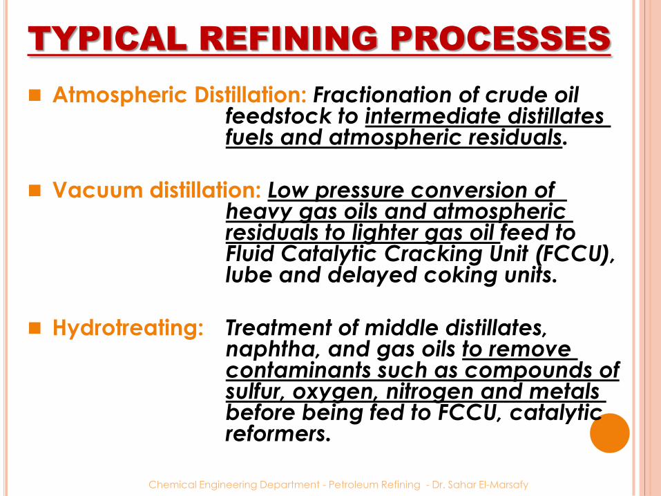
Atmospheric Distillation: Fractionation of crude oil feedstock to intermediate distillates fuels and atmospheric residuals.
Vacuum distillation: Low pressure conversion of heavy gas oils and atmospheric residuals to lighter gas oil feed to Fluid Catalytic Cracking Unit (FCCU), lube and delayed coking units.
Hydrotreating: Treatment of middle distillates, naphtha, and gas oils to remove contaminants such as compounds of sulfur, oxygen, nitrogen and metals before being fed to FCCU, catalytic reformers.
TYPICAL REFINING PROCESSES
Chemical Engineering Department - Petroleum Refining - Dr. Sahar El-Marsafy

Catalytic reforming: Improving the combustion quality of
atmospheric naphtha stream by
increasing its octane number before
blending to gasoline.
Isomerization: Conversion of paraffin-rich C5/C6 streams to
high octane product for blending with straight
run naphtha to gasoline
Hydrocracking: Upgrade of vacuum gas oils alone or
blended with various feedstock such as light
cycle oil, de-asphalted oil and coker gas oil to
lighter hydrocarbon for use as petrochemical
feedstock, low sulphur fuel oil and feed to FCCU,
isomerization and alkylation units.
TYPICAL REFINING PROCESSES
(CONT.)
Chemical Engineering Department - Petroleum Refining - Dr. Sahar El-Marsafy

Catalytic cracking: The selective conversion of atmospheric gas oils and residual feedstock to higher value cracked products for use as petrochemical feedstock, transportation fuels, middle distillates, and light cycle oil.
Coking: Conversion of hydro-treated and virgin vacuum residues, various petroleum tars and coal tar pitch through delayed coking to yield fuel gas, LPG, naphtha, gas oils, and coke.
Solvent De-Asphalting: Prepare quality feed for FCC units (de-asphalted oil) and hydro-crackers from vacuum residues and blending stocks for lube oil and asphalt manufacturing.
TYPICAL REFINING PROCESSES
(CONT.)
Chemical Engineering Department - Petroleum Refining - Dr. Sahar El-Marsafy

Gasoline blending: The physical mixture of a number of different hydrocarbons i.e. alkylate, isomerate, crackate and light straight run naphtha to produce a finished gasoline product with the desired characteristics
Sulfur recovery: Removal of dissolved H2S from produced liquid sulphur or converts hydrogen sulfide in sour gases and hydrocarbon streams to elemental sulfur
TYPICAL REFINING PROCESSES
(CONT.)
Chemical Engineering Department - Petroleum Refining - Dr. Sahar El-Marsafy

Hydrogen production: Production of hydrogen from refinery processes principally from catalytic reformer product gases and steam reforming
Liquefied petroleum gas (LPG) production: Gas plant separate refinery gas components including butanes for alkylation, pentanes for gasoline blending, LPG's for fuel, and ethane for petrochemicals.
TYPICAL REFINING PROCESSES
(CONT.)
Chemical Engineering Department - Petroleum Refining - Dr. Sahar El-Marsafy

Chemical Engineering Department - Petroleum Refining - Dr. Sahar El-Marsafy
DIAGRAMFLOWEFINERYR
Chemical Engineering Department - Petroleum Refining - Dr. Sahar El-Marsafy
Isomerization
Vapor recovery
Alkylation
Unsat. HC

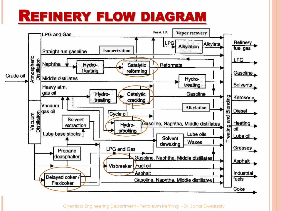
OVERALL REFINERY FLOW
PROCESS DESCRIPTION
1. The crude oil is heated in a furnace and
charged to an atmospheric distillation
tower, where it is separated into: butanes and lighter wet gas,
unstabilized light naphtha,
heavy naphtha,
kerosene,
atmospheric gas oil,
atmospheric reduced crude (ARC).
2. The topped crude is sent to the vacuum
distillation tower and separated into: vacuum gas oil stream
vacuum reduced crude bottoms (VRC).Chemical Engineering Department - Petroleum Refining - Dr. Sahar El-Marsafy

PROCESS DESCRIPTION (CONT.)
3. The wet gas streams from the crude unit, coker, and cracking units are separated in the vapor recovery section (gas plant) into: fuel gas,
liquefied petroleum gas (LPG),
unsaturated hydrocarbons (propylene, butylenes, and pentenes),
normal butane, and isobutane.
o The fuel gas is burned as a fuel in refinery furnaces and the normal butane is blended into gasoline or LPG.
o The unsaturated hydrocarbons and isobutaneare sent to the alkylation unit for processing.
Chemical Engineering Department - Petroleum Refining - Dr. Sahar El-Marsafy

4. The light naphtha streams from the crude
tower, coker and cracking units are sent to
an isomerization unit to convert straight-
chain paraffins into isomers that have higher
octane numbers.
5. The heavy naphtha streams from the crude
tower, coker, and cracking units are fed to
the catalytic reformer to improve their
octane numbers. The products from the
catalytic reformer are blended into regular
and premium gasolines for sale.
PROCESS DESCRIPTION (CONT.)
Chemical Engineering Department - Petroleum Refining - Dr. Sahar El-Marsafy

6. The atmospheric and vacuum crude unit gas oils and coker gas oil are used as feed stocks for the catalytic cracking or hydro-cracking units. These units crack the heavy molecules into lower
molecular weight compounds boiling in the gasoline and distillate fuel ranges.
The products from the hydrocracker are saturated.
The unsaturated catalytic cracker products are saturated and improved in quality by hydro-treating or reforming.
PROCESS DESCRIPTION (CONT.)
Chemical Engineering Department - Petroleum Refining - Dr. Sahar El-Marsafy
7. The alkylation unit uses either sulfuric or
hydrofluoric acid as catalyst to react
olefins with isobutane to form isoparaffins
boiling in the gasoline range.
The product is called alkylate, and is a high-
octane product blended into premium motor
gasoline and aviation gasoline.
8. The middle distillates from the crude unit,
coker, and cracking units are blended into
diesel and jet fuels and furnace oils.
PROCESS DESCRIPTION (CONT.)
Chemical Engineering Department - Petroleum Refining - Dr. Sahar El-Marsafy

9. The heavy vacuum gas oil and reduced crude from paraffinic or naphthenic base crude oils are processed into lubricating oils. After removing the asphaltenes in a propane deasphalting unit, the reduced crude bottoms is processed in a blocked operation with the vacuum gas oils to produce lube oil base stocks. The vacuum gas oils and deasphalted stocks are
first solvent-extracted to remove the aromatic compounds and then dewaxed to improve the pour point.
They are then treated with special clays or high-severity hydrotreating to improve their color and stability before being blended into lubricating oils.
PROCESS DESCRIPTION (CONT.)
Chemical Engineering Department - Petroleum Refining - Dr. Sahar El-Marsafy

10. The reduced crude bottoms (VRC) from
the vacuum tower is then thermally
cracked in a delayed coker to produce wet gas
coker gasoline
coker gas oil
coke
Without a coker, this heavy residue would
be sold for heavy fuel oil or (if the crude oil is
suitable) asphalt.
PROCESS DESCRIPTION (CONT.)
Chemical Engineering Department - Petroleum Refining - Dr. Sahar El-Marsafy
When a hydrocarbon is heated to a
sufficiently high temperature thermal
cracking occurs. This is sometimes referred
to as pyrolysis (especially when coal is the
feedstock). When steam is used it is called
steam cracking. When hydrogen is used it
is called hydrocracking.
We will examine two thermal processes
used in refineries.
Visbreaking
Delayed coking
THERMAL PROCESSES
Chemical Engineering Department - Petroleum Refining - Dr. Sahar El-Marsafy
OKINGC
Coking units convert heavy feedstocks into a solid
coke and lower boiling hydrocarbon products which
are suitable as feedstocks to other refinery units for
conversion into higher value transportation fuels.
From a chemical reaction viewpoint, coking can be
considered as a severe thermal cracking process in
which one of the end products is carbon (i.e., coke).
Actually the coke formed contains some volatile
matter or high-boiling hydrocarbons.
To eliminate essentially all volatile matter from
petroleum coke it must be calcined at approximately
2000 to 2300°F (1095 to 1260°C). Chemical Engineering Department - Petroleum Refining - Dr. Sahar El-Marsafy
OVERVIEW
o Coking is a thermal process for the conversion of heavy low grade oil to lighter products (mainly gasoline related). It can be considered as an improved version of thermal crackers.
o As a result of thermal cracking, coke is formed in the reactor.
o The first delayed coker was built by Standard Oil of Indiana at Whiting, Indiana in 1929.
o Removal of the coke deposit on the reactor wall was a major challenge.
o The development of hydraulic decoking was an important achievement after which a number of commercial cokers were built.
Chemical Engineering Department - Petroleum Refining - Dr. Sahar El-Marsafy

o The coke obtained is usually used as fuel or further treated to marketable products such as electrodes, metallurgical coke, etc.
o Majority of sulfur in oil is concentrated on coke, providing products with less sulfur which facilitate the downstream operations.
o The coke contains sulfur compounds and metal impurities, which must be removed before further treatment for environment consideration
OVERVIEW
Chemical Engineering Department - Petroleum Refining - Dr. Sahar El-Marsafy

o Coking is a semi-continuous operation as the solid coke should be removed from the reactor at certain times.
oCoke forms a thick solid layer over the reactor inner wall.
oCoking reactors are relatively large in size due to relatively large residence time.
o The reactor needs decoking upon completion of the process.
o Two or more reactors are used for continuous operation. One reactor is decoked while the other one is in operation.
OVERVIEW
Chemical Engineering Department - Petroleum Refining - Dr. Sahar El-Marsafy
PURPOSE
Coking was used primarily to pretreat vacuum
residuals to prepare coker gas oil streams suitable for
feed to a catalytic cracker.
Benefits:
This reduced coke formation on the cracker catalyst and
thereby allowed increased cracker throughputs.
This also reduced the net refinery yield of low-priced residual fuel.
Added benefit was obtained by reducing the metals content
of the catalytic cracker feed stocks.
In recent years coking has also been used to prepare
hydrocracker feedstocks and to produce a high
quality ‘‘needle coke’’ from stocks such as heavy
catalytic gas oils and decanted oils from the fluid
catalytic cracking unit.Chemical Engineering Department - Petroleum Refining - Dr. Sahar El-Marsafy
PRODUCTS& STOCKEEDF
The feed stock can be:
Straight run residue
Cracked residue
Vacuum distillation bottom product
The products are: Gases
Naphta
Fuel oil
Gas oil (major product, feedstock for catalytic cracking operations)
Coke
Chemical Engineering Department - Petroleum Refining - Dr. Sahar El-Marsafy

COKEPETROLEUMOFYPEST
Much of delayed coker coke is produced as hard, porous,
irregular-shaped lumps ranging in size from 20 inches (50
cm) down to fine dust. This type of coke is called sponge
coke because it looks like a black sponge.
A second form of petroleum coke being produced in
increasing quantities is needle coke. Needle coke derives its
name from its microscopic elongated crystalline structure.
Needle coke is produced from highly aromatic feed stocks
when a coking unit is operated at high pressures and high
recycle ratios (1: 1).
Needle coke is preferred over sponge coke for use in
electrode manufacture because of its lower electrical
resistivity and lower coefficient of thermal expansion.
Chemical Engineering Department - Petroleum Refining - Dr. Sahar El-Marsafy

Chemical Engineering Department - Petroleum Refining - Dr. Sahar El-Marsafy

Chemical Engineering Department - Petroleum Refining - Dr. Sahar El-Marsafy

Needle Coke
Chemical Engineering Department - Petroleum Refining - Dr. Sahar El-Marsafy

COKEPETROLEUMOFSESU
The main uses of petroleum coke are as follows:
1. Fuel
2. Manufacture of anodes for electrolytic cell
reduction of alumina
3. Direct use as chemical carbon source for
manufacture of elemental phosphorus, calcium
carbide, and silicon carbide
4. Manufacture of electrodes for use in electric
furnace production of elemental phosphorus,
titanium dioxide, calcium carbide, and silicon
carbide
5. Manufacture of graphite
Chemical Engineering Department - Petroleum Refining - Dr. Sahar El-Marsafy
COKINGELAYEDD
Delayed coking is a process in which the feed is sent
through a fired heater (480 – 515 C) with horizontal
tubes.
With short residence time in the furnace, coking of the feed is thereby delayed until it reaches large coking drums which provides long residence time to allow the cracking reactions to proceed to completion.
The cracked products leave as overheads and coke deposits form on the inner surface of the drum.
The temperature in the drum ranges from 415 to 450 C at pressures from 15 – 90 psig.
Chemical Engineering Department - Petroleum Refining - Dr. Sahar El-Marsafy

UNITCOKINGELAYEDD
Chemical Engineering Department - Petroleum Refining - Dr. Sahar El-Marsafy

The delayed coking process was developed to minimize refinery yields of residual fuel oil by severe thermal cracking of stocks such as vacuum residuals, aromatic gas oils, and thermal tars.
In early refineries, severe thermal cracking of such stocks resulted in unwanted deposition of coke in the heaters.
By gradual evolution of the art it was found that heaters could be designed to raise residual stock temperatures above the coking point without significant coke formation in the heaters. This required high velocities (minimum retention time) in the heaters.
DELAYED COKING
Chemical Engineering Department - Petroleum Refining - Dr. Sahar El-Marsafy

Typically furnace outlet temperatures range from
900–930°F (482–500°C).
The higher the outlet temperature, the greater the
tendency to produce shot coke and the shorter the
time before the furnace tubes have to be
decoked. Usually furnace tubes have to be
decoked every three to five months.
DELAYED COKING
Chemical Engineering Department - Petroleum Refining - Dr. Sahar El-Marsafy
PROCESS DESCRIPTION
1. Hot fresh liquid feed is charged to the
fractionator two to four trays above the bottom
vapor zone. This accomplishes the following:
The hot vapors from the coke drum are quenched by
the cooler feed liquid thus preventing any significant
amount of coke formation in the fractionator and
simultaneously condensing a portion of the heavy
ends which are recycled.
Any remaining material lighter than the desired coke
drum feed is stripped (vaporized) from the fresh liquid
feed.
The fresh feed liquid is further preheated making the
process more energy efficient.
Chemical Engineering Department - Petroleum Refining - Dr. Sahar El-Marsafy
2. The coke drum is usually on stream for 24 hours before becoming filled with coke.
Coke removal and cleaning operations usually takes less than 24 hours.
Coke is removed in three steps
Cooling the coke with water spray
Drilling a hole through the center of the deposit (opening the central top section of the drum)
Cutting the deposit with hydraulic devices (high pressure water jets)
PROCESS DESCRIPTION (CONT.)
Chemical Engineering Department - Petroleum Refining - Dr. Sahar El-Marsafy

PROCESS DESCRIPTION (CONT.)
The drum should be heated before receiving the
hot feed. Hot vapors from the online drum are
recirculated in the cold cleaned drum, where the
drum is heated (to about 350 C) and the vapors are
condensed and removed continuously.
During the operation, vapors are continuously
condensed, cracked and coke is gradually built up
on the inner wall of the drum.
Different types of coke may be formed depending
on the type of the feed and the operating
conditions.
Chemical Engineering Department - Petroleum Refining - Dr. Sahar El-Marsafy
3. Vapors from the top of the coke drum return to the base of the fractionator. These vapors consist of steam and the products
of the thermal cracking reaction: gas, naphtha, and gas oils. The vapors flow up through the quench trays. Above the fresh feed entry in the fractionator there are usually two or three additional trays below the gas oil drawoff tray.
These trays are refluxed with partially cooled gas oil in order to provide fine trim control of the gas oil end point and to minimize entrainment of any fresh feed liquid or recycle liquid into the gas oil product.
PROCESS DESCRIPTION (CONT.)
Chemical Engineering Department - Petroleum Refining - Dr. Sahar El-Marsafy
4. The gas oil side draw is a conventional configuration employing a six- to eight-tray stripper with steam introduced under the bottom tray for vaporization of light ends to control the initial boiling point (IBP) of the gas oil. Steam and vaporized light ends are returned from the
top of the gas oil stripper to the fractionator one or two trays above the draw tray.
A pump-around reflux system is provided at the draw tray to recover heat at a high temperature level and minimize the low-temperature-level heat removed by the overhead condenser.
This low-temperature-level heat cannot normally be recovered by heat exchange and is rejected to the atmosphere through a water cooling tower.
PROCESS DESCRIPTION (CONT.)
Chemical Engineering Department - Petroleum Refining - Dr. Sahar El-Marsafy

5. The bottom product of the fractionator is recycled back to the reactor after being
combined with the preheated feed.
Steam must be used before the switch and
immediately after the switch for stripping the
unconverted liquid feed to avoid feed solidification
during the cooling process which creates major
problems in the operation.
Steam stripping also serves to transfer heat from the
hot bottom to the unconverted feed on top of the
coke drum.
PROCESS DESCRIPTION (CONT.)
Chemical Engineering Department - Petroleum Refining - Dr. Sahar El-Marsafy