pertanika j. sci. & technol. 20 (2): 221 - 241 (2012 ...psasir.upm.edu.my/40452/1/11. a behavior...
TRANSCRIPT

Pertanika J. Sci. & Technol. 20 (2): 221 - 241 (2012)
SCIENCE & TECHNOLOGYJournal homepage: http://www.pertanika.upm.edu.my/
ISSN: 0128-7680 © 2012 Universiti Putra Malaysia Press.
INTRODUCTION
In Malaysia, the increasing cost of land prices in the urban areas has forced the building industry to look for cheaper land for construction, many a times on poor ground conditions, particularly on peat. Various ground improvement techniques,
A Behavior of Reinforced Vibrocompacted Stone Column in Peat
Arun Prasad1*, Sina Kazemian2, Behzad Kalantari3 and Bujang B. K. Huat4
1Department of Civil Engineering, Indian Institute of Technology (BHU), Varanasi – 221005, India2Department of Civil Engineering, Bojnourd Branch, Islamic Azad University, Bojnourd, Iran3Department of Civil Engineering, Hormozgan University, Bandar abbas, Iran4Department of Civil Engineering, Faculty of Engineering, University Putra Malaysia, 43400 Serdang, Selangor, Malaysia
ABSTRACT
In the literature, several methods of ground improvement have been presented including compacted stone columns. The bearing capacity of the granular column is governed mainly by the lateral confining pressure mobilized in the soft soil to restrain or prevent bulging of the granular column. Therefore, the technique becomes unfeasible in peat that does not provide sufficient lateral confinement. This condition can be overcome by encasing the stone column with geogrid. This paper investigates the performance of the geogrid encased vibrocompacted stone column in peat. This study was carried out using PLAXIS software equipped with unit cell concept. The peat was modelled using soft soil model and the stone column using Mohr-Coulomb soil model, respectively. The geogrid was modelled using the geogrid option and could take only tensile force. The results indicate that the geogrid encased stone column can take much higher load in comparison to ordinary stone columns as the stiffness of the column increases. Meanwhile, the length of encasement also varied and it was observed that it was very effective up to about two times the diameter of the column. It also increased the column stiffness, and therefore led to a significant strain reduction. It was also observed that the columns at a spacing of three times the diameter are very effective. The results presented here can be used by the geotechnical engineers to design the geogrid reinforced stone column based on the strength of the soil, diameter of the column, spacing of the columns and stiffness of the geogrid.
Keywords: Peat, Stabilization, Stone column, Unit cell, Geogrid encasement, finite element
Article History:Received: 22 April 2010Accepted: 2 November 2011
Email addresses:[email protected] (Arun Prasad), [email protected] (Sina Kazemian), [email protected] (Behzad Kalantari), [email protected] (Bujang B. K. Huat)*Corresponding Author

Arun Prasad, Sina Kazemian, Behzad Kalantari and Bujang B. K. Huat
222 Pertanika J. Sci. & Technol. 20 (2): 221 - 241 (2012)
such as compacted-stone, have been increasingly used to reinforce soft soils and to increase the bearing capacity of the foundation soil (Aboshi et al., 1979; Al-Homud & Degen, 2006; Ambily & Gandhi, 2007; Goughnour & Bayuk, 1979; Chen et al., 2008; Christoulas et al., 1997; Elshazly et al., 2007, 2008; Li & Rowe 2008; Narsimha et al., 1992). This ground improvement technique has been successfully applied for foundation of structures like liquid storage tanks, earthen embankments, raft foundations, etc., where a relatively large settlement can be tolerated by the structure. It is preferred among other methods as it gives the advantage of reduced settlements and also accelerated consolidation settlements due to reduction in the drainage paths (Han & Gabr, 2002). The stone columns develop their load carrying capacity through bulging, while near-passive pressure conditions are developed in the surrounding soil. Several papers have been published on the stone column as a ground reinforcing technique. The bearing capacity and settlement response of the reinforced soil depend upon several parameters, the mechanical properties of the granular column, the native soft soil including the replacement factor, as well as the group effect and the loading process and rate, and the radial drainage through the columns. The technique is most effective in soft soils with undrained shear strength ranging from 15-50 kPa (Juran & Guermazi 1988). However, it becomes unfeasible in more compressible soils, such as peat, which do not provide sufficient lateral confinement.
In weak deposits, the lateral support is significantly low and the column fails by bulging. In order to improve the performance of the stone columns when treating weak deposits, it is imperative that the tendency of the columns to bulge should be resisted or prevented effectively. This will facilitate an increase of the load transfer through the stone column and thus enhance the load-carrying capacity. Such a condition can be achieved through encasement of stone columns through geosynthetics over the full or partial height of the column (Alexiew et al., 2005; Black et al., 2007; de Mello et al., 2008; Gniel & Bouazza, 2009; Huang & Han 2009; Kempfert, 2003; Murugesan & Rajagopal, 2006, 2009, 2010; Raithel et al., 2002; Yoo & Kim, 2009). The geosynthetic encasement will significantly increase the load carrying capacity of the stone columns due to the additional confinement from the geosynthetic. The geosynthetic encasement will also prevent the lateral squeezing of stones when the stone column is installed in some extremely soft soils, and this will lead to a minimal loss of stones.Murugesan and Rajagopal (2010) carried out a load test on single and group of geogrid encased columns and concluded that the load capacity and stiffness of the stone column could be increased by all-round encasement by geosynthetic. The performance of the encased stone columns of smaller diameters was found to be superior than that of the larger diameter stone columns for the same encasement because of the mobilization of higher confining stresses in smaller diameter stone columns. Meanwhile, the elastic modulus of the geosynthetic encasement plays an important role in enhancing the capacity and stiffness of the encased columns.
Black et al. (2007) examined the performance of stone columns by jacketing them with tubular wire mesh and observed that the bearing capacity of soft soil could be improved using this particular technique.
Ayadat and Hanna (2005) performed an experimental investigation on the load carrying capacity and the settlement of the geogrid encased stone columns and concluded that the
A Behavior of Reinforced Vibrocompacted Stone Column in Peat
223Pertanika J. Sci. & Technol. 20 (2): 221 - 241 (2012)
ultimate carrying capacity of a stone column increased with the increase in the stiffness of the geofabric material used to encapsulate the sand column.
A method to estimate the settlement of foundation resting on the infinite grid of stone columns based on the unit cell concept was proposed by Priebe (1995). In this concept, the soil around a stone column for an area that was represented by a single column and dependent upon the column spacing was considered for the analysis. As all the columns in such analyses are simultaneously loaded, it is assumed that the lateral deformations in soil at the boundary of unit cell are zero. The behaviour of all column soil units is the same except near the edges of the loaded area, and thus only one column soil unit needs to be analyzed (Balaam & Booker, 1985). The unit cell concept has also been used (Ambily & Gandhi, 2007; Goughnour, 1983; Yoo & Kim, 2009). The modelling of a group of columns using unit cell concept was carried out by Mitchell and Huber (1985). In this modelling, the group of columns surrounding the central column was replaced by a ring of stone material having an equivalent thickness. The technique can be limited by the relatively large settlements that occur as a result of minimal compaction received during installation and also geotextile strain during loading. As such, the current research work focused on using stiffer geosynthetics such as geogrid for encasement.
In the present study, the effectiveness of geogrid encasement on the vibrocompacted stone columns is investigated through parametric study carried out by commercially available finite element package PLAXIS. The effects of the parameters, such as the stiffness of geogrid encasement, the depth of encasement from ground level, the diameter of stone columns, as well as spacing of the stone columns and shear strength of the surrounding peat, were analyzed. The simulation of the column installation in peat by means of vibro-compaction technique is as per the method described by Guetif et al. (2003, 2007). The analyses were carried out assuming a unit cell concept for columns that were arranged in a triangular pattern and the deformations in peat were restrained within the unit cell represented by the equivalent area of each column. The analysis for a group of columns was carried out as the group of columns surrounding the central column replaced by a ring of stone material having equivalent thickness (Mitchell & Huber 1985).
fINITE ELEMENT ANALYSIS
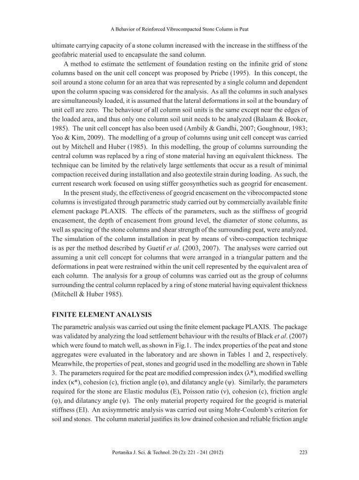
The parametric analysis was carried out using the finite element package PLAXIS. The package was validated by analyzing the load settlement behaviour with the results of Black et al. (2007) which were found to match well, as shown in Fig.1. The index properties of the peat and stone aggregates were evaluated in the laboratory and are shown in Tables 1 and 2, respectively. Meanwhile, the properties of peat, stones and geogrid used in the modelling are shown in Table 3. The parameters required for the peat are modified compression index (λ*), modified swelling index (κ*), cohesion (c), friction angle (φ), and dilatancy angle (ψ). Similarly, the parameters required for the stone are Elastic modulus (E), Poisson ratio (ν), cohesion (c), friction angle (φ), and dilatancy angle (ψ). The only material property required for the geogrid is material stiffness (EI). An axisymmetric analysis was carried out using Mohr-Coulomb’s criterion for soil and stones. The column material justifies its low drained cohesion and reliable friction angle
Arun Prasad, Sina Kazemian, Behzad Kalantari and Bujang B. K. Huat
224 Pertanika J. Sci. & Technol. 20 (2): 221 - 241 (2012)
value as the choice is for well-graded gravel. As recommended in Brinkgreve and Vermeer (1998), the angle of dilatancy is taken null for peat, this being extremely soft. An undrained condition is assumed for peat and drained for columns. This condition is justified in the peat as large consolidation settlement takes place after the application of the load.
The stone columns are usually installed in a triangular plan pattern in the field; for design and analysis purposes, a cylindrical unit cell considered consists of stone column and soil from the affected area. The concept of the composite cell model has been considered by many
(a) Black et al. (2007)
(b) Narasimha Rao et al. (1992)
Fig.1: Validation of Plaxis by the results of (a) Black et al., 2007, and (b) Narasimha Rao et al., 1992.

A Behavior of Reinforced Vibrocompacted Stone Column in Peat
225Pertanika J. Sci. & Technol. 20 (2): 221 - 241 (2012)
researchers for investigating several aspects of reinforced soils by columns, such as increase of bearing capacity, prediction of settlement, and reduction of soil consolidation (Bouassida et al., 1995; Guetif et al., 2003, 2007). The influenced areas for stone columns installed in triangular plan patterns were calculated from that of an equivalent hexagonal area. Barron (1948) suggested a method to calculate the radius of the circular influenced area as 0.525s for the triangular pattern, where ‘s’ is the centre to centre spacing between the stone columns. The cylindrical unit cell has been idealized in the finite element model, using axisymetric model with the radial symmetry around the vertical axis that passes through the centre of the stone column.
Drainage was permitted from the top as in the oedometric test, as the soil profile was assumed to be 5.0 m thick peat underlain by a hard stratum. As the columns are installed by vibro-compaction, the interface between the column and soft clay is assumed to be perfectly rigid. This implies that the shear stresses can occur at the contact between the column and the peat. The contact between the column and the peat is assumed pervious, while the borders of the composite cell model are kept impervious, except for the top level since the stone columns are installed in a short period of time, and the expansion process is considered to occur in undrained conditions. The simulation of the vibrocompacted stone column was carried out following the procedure discussed by Guetif et al. (2007). It consisted of modelling the cylindrical hole occupied by the vibroprobe with a radius of 0.25 m by a fictitious purely elastic material having a weakest Young’s modulus equivalent to 25 kPa [see Fig.2(a)]. Then, along the border of the cylindrical hole, the peat was subjected to the radial displacement that simulated the vibro-compaction installation until the horizontal expansion reached the column radius of 0.3 m or 0.5 m, as shown in Fig.2(b). Finally, the real parameters of the column material (Table 3) were introduced for further calculation using the PLAXIS.
This numerical study was carried out using the PLAXIS software as an axisymmetric model and the results were found to have matched well with the composite cell model. The typical finite element mesh consisted of 1750 nodes and 550 15-node triangular elements. Since the lateral expansion generates large strains in the soft soil in the neighbourhood of column, the updated mesh option provided by the Plaxis software was adopted to take care of this (Guetif et al., 2007). In order to incorporate the reinforcing effect during the column installation and the consolidation occurring in peat, a two stage modelling was performed; firstly, the undrained expansion of the column within peat, and secondly, the consolidation of the improved peat till the excess pore water pressure was reduced to the minimum (Debats et al., 2003).
Nonetheless, the creep effects of the geogrid were not considered in this study by assuming that the hoop tension force developed in the encasement was much smaller than the tensile capacity of the geogrid (Murugesan & Rajagopal, 2006). The radial deformation was restricted along the periphery of the tank but settlement was allowed, and along the bottom of the tank, both the radial deformation and settlement were also restricted. It is crucial to note that no interface element was used at the interface between the stone column and the peat, as the deformation of the column was mainly by radial bulging and no significant shear was possible (Mitchell & Huber, 1985). The external loading was applied in the form of a displacement equivalent to 20% of the column diameter.

Arun Prasad, Sina Kazemian, Behzad Kalantari and Bujang B. K. Huat
226 Pertanika J. Sci. & Technol. 20 (2): 221 - 241 (2012)
RESULTS AND DISCUSSION
In order to evaluate the improvement achieved due to the geogrid encasement, two cases were analyzed, namely, the stone columns without geogrid encasement (SC) and the stone columns encased with geogrid (GC). In order to directly assess the influence of the confinement effects due to encasement, the analyses were performed by applying uniform pressure on the stone column portion alone. Meanwhile, the analysis was also performed by applying load on the entire area of the unit cell and finally loading was applied to group of columns having seven columns arranged in a triangular pattern.
As mentioned earlier, the model was validated by analyzing the load settlement’s behaviour with the results of Black et al. (2007) and Narsimha Rao et al. (1992). These results are
(a) Model of the stone column with a dummy column
(b) Stone column modelled (column expansion)
Fig.2: Stone column installations by simulating column expansion
A Behavior of Reinforced Vibrocompacted Stone Column in Peat
227Pertanika J. Sci. & Technol. 20 (2): 221 - 241 (2012)
presented in Fig.1. Three cases were investigated, namely; no column, granular column, and jacketed granular column. The results of PLAXIS showed some deviations with the results of Black et al. (2007) for the case with no column, which was probably due to the fact that the peat used in the present analysis was more compressible as compared with clay used by Black et al. (2007). As for all the other cases, a reasonable matching was shown. Similarly, the results of PLAXIS also revealed a very small deviation with the results of Narsimha Rao et al. (1992), as shown in Fig.1(b), and this could be attributed to the different nature of soils used in the analyses.
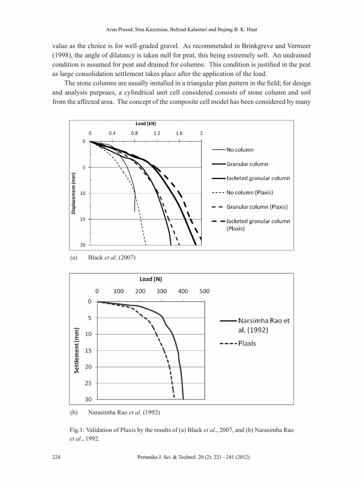
(a) Deformed mesh for column area alone loaded for SC
(b) Deformed mesh for column area alone loaded for GC
Fig.3: Deformed mesh for SC and GC, s/d = 3, c = 6 kPa, diameter = 1.0m, geogrid upto 3d

Arun Prasad, Sina Kazemian, Behzad Kalantari and Bujang B. K. Huat
228 Pertanika J. Sci. & Technol. 20 (2): 221 - 241 (2012)
All the analyses for column diameters (0.6 m and 1.0 m) and the group of seven columns were carried out by varying s/d from 2 to 4, geogrid stiffness from 50 to 5000 kN/m, the length of encasement from 1d to 4d from the top (d is the diameter and s is the centre to centre spacing of the columns). Also, three different combinations of shear strength parameters, cohesion and angle of internal friction of the peat were used: 4 kPa & 16°, 6 kPa & 18° and 8 kPa & 20°, respectively. The loading was applied in terms of the prescribed displacement equivalent to 20% of the column diameter. All the cases were idealized through axisymmetric modelling, whereas the improved performance was evaluated based on the reduced settlement and the lateral bulging of the stone column.
Fig.3 show the typical deformed mesh, at a prescribed displacement, for the case of column alone loaded for SC and GC for s/d = 3 and c = 6 kPa. It was observed that failure was caused by the bulging of the column at a depth about 0.5 to 2.0 times the diameter of the column [Fig.3(a)]. The bulging disappeared when the column was encased with geogrid, as illustrated in Fig.3(b).
Fig.4 shows a typical deformed mesh for SC, when the entire area was loaded for s/d = 3 and c = 6 kPa. Nevertheless, no bulging of the column was observed. The analysis was also carried out for a group of seven columns using the axisymmetric model with surrounding six columns that were replaced by a ring of stones having equivalent thickness and material properties of stone, as adopted by Mitchell and Huber (1985).
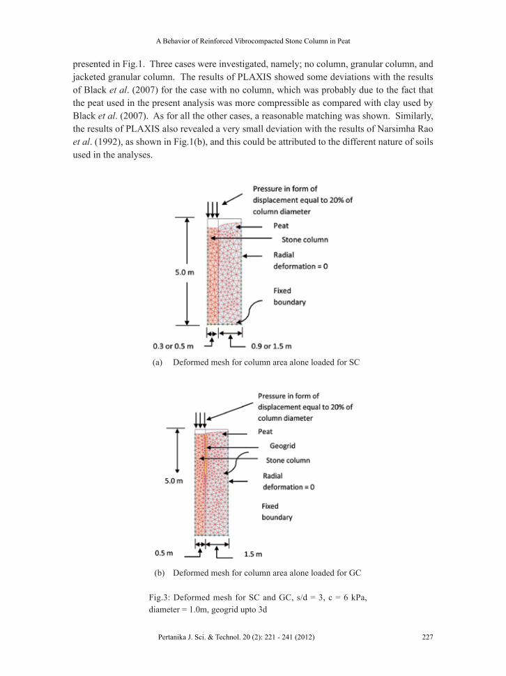
A typical deformed mesh for the group of seven columns is shown in Fig.5. For this study, s/d was varied from 2 to 4 and c ranged from 4 to 8 kPa.
Effect of the Shear Strength
The impact of the strength of the foundation soil was studied by performing some analyses and the pressure-settlement responses observed are shown in Fig.6 for s/d = 3. The pressure
Fig.4: Deformed mesh, entire area loaded, single column ( SC), s/d = 3, c = 6 kPa, diameter = 1.0m
A Behavior of Reinforced Vibrocompacted Stone Column in Peat
229Pertanika J. Sci. & Technol. 20 (2): 221 - 241 (2012)
at a displacement equivalent to 20% of the column diameter is 150.6 kPa for the peat with a cohesion equivalent to 4 kN/m2. This increased to 245.4 kPa for the peat with a cohesion equivalent to 8 kN/m2. A similar behaviour was also observed for the other s/d values.
It was observed that the load capacity of the SC was dependent on the cohesive strength of the surrounding clay soil. On the other hand, the effect of the strength of the surrounding soil on the load capacity of the GC gradually decreased as the stiffness of the geogrid was increased. When the encasement stiffness was increased from 50 to 5000 kN/m, the pressure–settlement response of GC was practically independent of the strength of the surrounding clay soil, as shown in Fig.7.
As the stiffness of the encasement increases, the lateral bulging of the stone column reduces, thereby reducing the stresses transferred into the surrounding soil. Hence, it can be said that the contribution of the surrounding soil to the stability of the encased stone column reduces as the stiffness of the encasement increases. This implies that the capacity of the encased
(a)
(b)
Fig.5: (a) Deformed mesh, entire area loaded, a group of seven columns (SC), s/d = 3, c = 6 kPa, diameter = 1.0 m; (b) plan view of the group layout

Arun Prasad, Sina Kazemian, Behzad Kalantari and Bujang B. K. Huat
230 Pertanika J. Sci. & Technol. 20 (2): 221 - 241 (2012)
columns is almost independent of the strength of the surrounding soil for tje extremely stiff geogrid encasement. Murugesan and Rajagopal (2006, 2010) also observed that the stiffness of the encasement plays an important role in reducing the bulging of the columns, and thus leading to a higher bearing capacity of the columns.
Fig.6: Pressure vs. settlement curves for different shear strengths; s/d = 3, diameter = 0.6 m, encasement up to 2d
Fig.7: Pressure vs. settlement curves; different shear strengths and different geogrid encasement stiffness; column diameter = 0.5 m, s/d =3 (NE = No encasement)
A Behavior of Reinforced Vibrocompacted Stone Column in Peat
231Pertanika J. Sci. & Technol. 20 (2): 221 - 241 (2012)
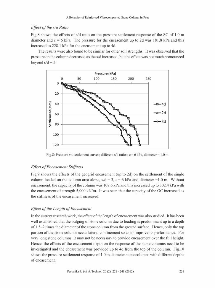
Effect of the s/d Ratio
Fig.8 shows the effects of s/d ratio on the pressure-settlement response of the SC of 1.0 m diameter and c = 6 kPa. The pressure for the encasement up to 2d was 181.8 kPa and this increased to 228.1 kPa for the encasement up to 4d.
The results were also found to be similar for other soil strengths. It was observed that the pressure on the column decreased as the s/d increased, but the effect was not much pronounced beyond s/d = 3.
Fig.8: Pressure vs. settlement curves; different s/d ratios; c = 6 kPa, diameter = 1.0 m
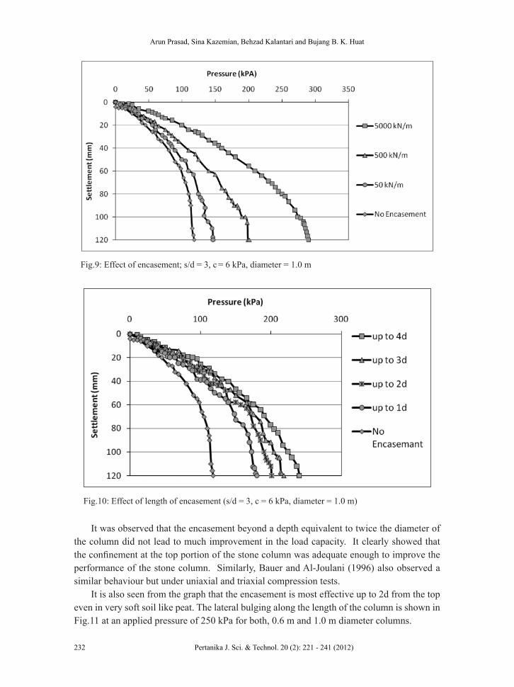
Effect of Encasement Stiffness
Fig.9 shows the effects of the geogrid encasement (up to 2d) on the settlement of the single column loaded on the column area alone, s/d = 3, c = 6 kPa and diameter =1.0 m. Without encasement, the capacity of the column was 108.6 kPa and this increased up to 302.4 kPa with the encasement of strength 5,000 kN/m. It was seen that the capacity of the GC increased as the stiffness of the encasement increased.
Effect of the Length of Encasement
In the current research work, the effect of the length of encasement was also studied. It has been well established that the bulging of stone column due to loading is predominant up to a depth of 1.5–2 times the diameter of the stone column from the ground surface. Hence, only the top portion of the stone column needs lateral confinement so as to improve its performance. For very long stone columns, it may not be necessary to provide encasement over the full height. Hence, the effects of the encasement depth on the response of the stone columns need to be investigated and the encasement was provided up to 4d from the top of the column. Fig.10 shows the pressure-settlement response of 1.0 m diameter stone columns with different depths of encasement.
Arun Prasad, Sina Kazemian, Behzad Kalantari and Bujang B. K. Huat
232 Pertanika J. Sci. & Technol. 20 (2): 221 - 241 (2012)
It was observed that the encasement beyond a depth equivalent to twice the diameter of the column did not lead to much improvement in the load capacity. It clearly showed that the confinement at the top portion of the stone column was adequate enough to improve the performance of the stone column. Similarly, Bauer and Al-Joulani (1996) also observed a similar behaviour but under uniaxial and triaxial compression tests.
It is also seen from the graph that the encasement is most effective up to 2d from the top even in very soft soil like peat. The lateral bulging along the length of the column is shown in Fig.11 at an applied pressure of 250 kPa for both, 0.6 m and 1.0 m diameter columns.
Fig.9: Effect of encasement; s/d = 3, c = 6 kPa, diameter = 1.0 m
Fig.10: Effect of length of encasement (s/d = 3, c = 6 kPa, diameter = 1.0 m)
A Behavior of Reinforced Vibrocompacted Stone Column in Peat
233Pertanika J. Sci. & Technol. 20 (2): 221 - 241 (2012)
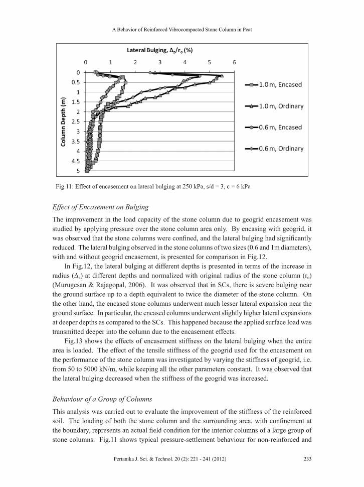
Fig.11: Effect of encasement on lateral bulging at 250 kPa, s/d = 3, c = 6 kPa
Effect of Encasement on Bulging
The improvement in the load capacity of the stone column due to geogrid encasement was studied by applying pressure over the stone column area only. By encasing with geogrid, it was observed that the stone columns were confined, and the lateral bulging had significantly reduced. The lateral bulging observed in the stone columns of two sizes (0.6 and 1m diameters), with and without geogrid encasement, is presented for comparison in Fig.12.
In Fig.12, the lateral bulging at different depths is presented in terms of the increase in radius (Δz) at different depths and normalized with original radius of the stone column (ro) (Murugesan & Rajagopal, 2006). It was observed that in SCs, there is severe bulging near the ground surface up to a depth equivalent to twice the diameter of the stone column. On the other hand, the encased stone columns underwent much lesser lateral expansion near the ground surface. In particular, the encased columns underwent slightly higher lateral expansions at deeper depths as compared to the SCs. This happened because the applied surface load was transmitted deeper into the column due to the encasement effects.
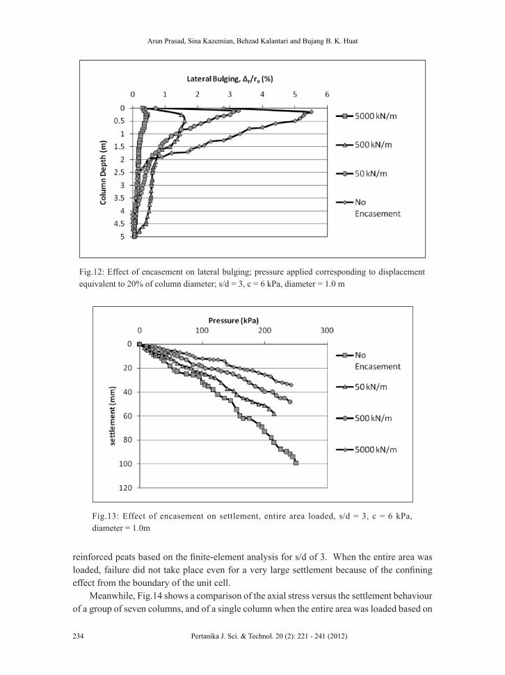
Fig.13 shows the effects of encasement stiffness on the lateral bulging when the entire area is loaded. The effect of the tensile stiffness of the geogrid used for the encasement on the performance of the stone column was investigated by varying the stiffness of geogrid, i.e. from 50 to 5000 kN/m, while keeping all the other parameters constant. It was observed that the lateral bulging decreased when the stiffness of the geogrid was increased.
Behaviour of a Group of Columns
This analysis was carried out to evaluate the improvement of the stiffness of the reinforced soil. The loading of both the stone column and the surrounding area, with confinement at the boundary, represents an actual field condition for the interior columns of a large group of stone columns. Fig.11 shows typical pressure-settlement behaviour for non-reinforced and
Arun Prasad, Sina Kazemian, Behzad Kalantari and Bujang B. K. Huat
234 Pertanika J. Sci. & Technol. 20 (2): 221 - 241 (2012)
reinforced peats based on the finite-element analysis for s/d of 3. When the entire area was loaded, failure did not take place even for a very large settlement because of the confining effect from the boundary of the unit cell.
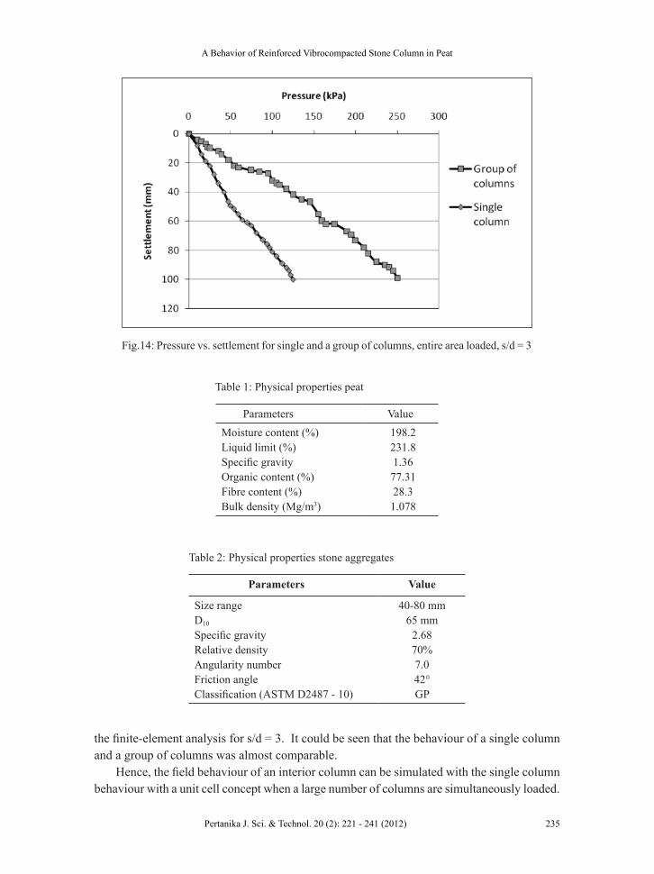
Meanwhile, Fig.14 shows a comparison of the axial stress versus the settlement behaviour of a group of seven columns, and of a single column when the entire area was loaded based on
Fig.12: Effect of encasement on lateral bulging; pressure applied corresponding to displacement equivalent to 20% of column diameter; s/d = 3, c = 6 kPa, diameter = 1.0 m
Fig.13: Effect of encasement on settlement, entire area loaded, s/d = 3, c = 6 kPa, diameter = 1.0m
A Behavior of Reinforced Vibrocompacted Stone Column in Peat
235Pertanika J. Sci. & Technol. 20 (2): 221 - 241 (2012)
the finite-element analysis for s/d = 3. It could be seen that the behaviour of a single column and a group of columns was almost comparable.
Hence, the field behaviour of an interior column can be simulated with the single column behaviour with a unit cell concept when a large number of columns are simultaneously loaded.
Table 1: Physical properties peat
Parameters ValueMoisture content (%) 198.2Liquid limit (%) 231.8Specific gravity 1.36Organic content (%) 77.31Fibre content (%) 28.3Bulk density (Mg/m3) 1.078
Table 2: Physical properties stone aggregates
Parameters Value
Size range 40-80 mmD10 65 mmSpecific gravity 2.68Relative density 70%Angularity number 7.0Friction angle 42°Classification (ASTM D2487 - 10) GP
Fig.14: Pressure vs. settlement for single and a group of columns, entire area loaded, s/d = 3

Arun Prasad, Sina Kazemian, Behzad Kalantari and Bujang B. K. Huat
236 Pertanika J. Sci. & Technol. 20 (2): 221 - 241 (2012)
Table 3: Material properties used in modelling
Materials Peat Stone GeogridMaterial model Soft soil Mohr-Coulomb ElasticType of behaviour Undrained Drained --Bulk density (Mg/m3) -- 2.0 --Elastic modulus, E (kPa) -- 3.0x10⁴ --Poisson’s ratio, ν -- 0.3 --Modified compression index, λ* 0.2 -- --Modified swelling index, κ* 0.01 -- --Cohesion, c (kPa) 4, 6, 8 0.01 --Friction angle, φ (°) 16, 18, 20 42 --Dilatancy angle, ψ (°) 0 10 --Hydraulic conductivity, k (m/day) -- 100 --Stiffness, EI (kN/m) -- -- 50, 500, 5000
A similar behaviour of a group of columns has also been reported by Dhouib and Blondeau (2005), as well as Maurya et al. (2005).
Further, the pressure at a prescribed settlement equivalent to 20% of the column diameter was evaluated for all the cases (column area alone loaded) and is presented in Table 4. In addition, the settlement at a specified pressure (group of columns) for the entire area loaded was calculated and the results are presented in Table 5.
CONCLUSIONS
The performance of the stone columns encased with geogrid reinforcement was studied in this research work. The results from the parametric studies have been presented to show the effects of confinement for improvement in the load capacity of the stone column due to geogrid encasement. The installation of the stone column in peat was simulated by adopting the composite cell model. Meanwhile, the numerical analyses were carried out by using the finite element software PLAXIS. The simulation shows a significant improvement in the characteristics of the peat subjected to vibro-compacted column encased with geogrid.
Based on the results obtained in this study, the following conclusions were made:
● The load carrying capacity and the stiffness of the stone column in peat can be increased by encasing the stone column by geogrid. The lateral bulging is minimized by geogrid encasement as the stone columns are confined.
● The stiffness of the geogrid encasement is very important in increasing the load capacity and the stiffness of the geogrid encased stone columns.
● The performance of the geogrid encased stone columns of smaller diameters (0.6 m) is better than that of stone columns with larger diameter (1.0 m) in peat due to the mobilization of higher confining stresses in a larger stone column.

A Behavior of Reinforced Vibrocompacted Stone Column in Peat
237Pertanika J. Sci. & Technol. 20 (2): 221 - 241 (2012)
Tabl
e 4:
Pre
ssur
e at
20%
settl
emen
t (co
lum
n ar
ea a
lone
load
ed)
Col
umn
diam
eter
(m
)Sh
ear s
treng
th
(kN
/m2 )
Spac
ing
of
colu
mns
No
enca
sem
ent
Leng
th o
f enc
asem
ent
1d2d
3d4d
Geo
grid
tens
ile st
iffne
ss (k
N/m
)50
500
5000
5050
050
0050
500
5000
5050
050
000.
64
2d10
585
170
248
140
191
294
147
204
317
154
229
340
3d10
011
215
121
311
716
826
312
018
328
212
420
129
64d
8210
414
721
011
016
526
011
518
127
911
519
629
06
2d13
715
520
027
017
322
532
018
224
034
519
127
037
03d
118
140
180
235
147
201
290
151
218
310
151
240
325
4d11
213
217
122
614
019
228
014
621
130
114
623
031
38
2d16
417
622
429
419
725
234
820
726
937
620
630
240
33d
143
161
200
254
169
223
314
173
241
336
178
266
353
4d13
415
219
324
816
121
630
816
823
833
116
825
934
41.
04
2d19
222
819
222
824
735
755
225
838
760
327
541
362
43d
161
201
161
201
219
338
505
233
340
540
239
365
560
4d15
519
115
519
121
033
049
322
333
553
522
935
855
16
2d25
328
237
049
030
542
060
031
845
565
532
948
667
83d
220
251
338
441
274
397
555
292
405
590
299
430
610
4d21
024
232
932
126
738
854
228
339
457
829
042
059
88
2d30
332
130
332
134
747
065
436
251
071
437
554
473
93d
268
288
268
288
315
441
602
338
450
640
344
477
662
4d25
127
925
124
230
843
159
632
744
463
532
346
865
7

Arun Prasad, Sina Kazemian, Behzad Kalantari and Bujang B. K. Huat
238 Pertanika J. Sci. & Technol. 20 (2): 221 - 241 (2012)
Tabl
e 5:
Set
tlem
ent a
t the
spec
ified
pre
ssur
e (a
gro
up o
f col
umns
)
Col
umn
diam
eter
(m
)Sh
ear s
treng
th
(kN
/m2 )
Spac
ing
of
colu
mns
No
enca
sem
ent
Leng
th o
f enc
asem
ent
1d2d
3d4d
Geo
grid
tens
ile st
iffne
ss (k
N/m
)50
500
5000
5050
050
0050
500
5000
5050
050
000.
64
2d50
3934
2733
2519
2920
1424
1612
3d65
5245
3544
3126
3824
2233
2119
4d80
6254
4452
4233
4634
3239
2826
62d
4234
3024
2922
1725
1813
2114
113d
5345
4032
3828
2433
2120
2919
174d
6754
4840
4538
3040
3029
3425
248
2d32
2826
2224
1915
2015
1117
1110
3d39
3634
2830
2321
2523
1822
1615
4d49
4341
3636
3227
2725
3227
2121
1.0
42d
107
8271
4474
4833
6341
2854
3624
3d12
192
7849
8158
3971
50
3559
4430
4d13
410
391
5792
7045
7958
4166
5334
62d
9072
6340
6543
3055
3726
4832
223d
9980
7045
7152
3662
4532
5240
274d
112
8981
5280
6241
6953
3758
4831
82d
6858
5436
5337
2744
3023
3827
193d
7264
5948
5644
3249
3529
4132
244d
8370
6048
6353
3855
4231
4638
28

A Behavior of Reinforced Vibrocompacted Stone Column in Peat
239Pertanika J. Sci. & Technol. 20 (2): 221 - 241 (2012)
● The encasement of the stone column up to a depth equivalent to two times the diameter of the stone column can substantially increase its load carrying capacity as the maximum bulging is at a depth of about 1.5 times of the diameter of the column.
● The load capacity of the stone column decreases as the spacing increases up to s/d of 3, beyond which, there is very small change.
● The field behaviour of an interior column when a large number of columns are simultaneously loaded can be simulated with a single column test using a unit cell concept.
REfERENCESAboshi, H., Ichimoto, E., Harada, K., & Emoki, M. (1979). The composer - A method to improve the
characteristics of soft clays by inclusion of large diameter sand columns. Proc., Int. Conf. on Soil Reinforcement., E.N.P.C., 1, Paris, 211-216.
Alexiew, D., Brokemper, D., & Lothspeich, S. (2005). Geotextile encased columns (gec): load capacity, geotextile selection and pre-design graphs. Proceedings of Geo- Frontiers 2005, Austin, Texas, US, 497-510.
Al-Homud, A., & Degen, W. (2006). Marine stone columns to prevent earthquake induced soil liquefaction. Geotech. Geol. Eng., 24(3), 775-790.
Ambily, A. P., & Gandhi, S. R. (2007). Behavior of stone columns based on experimental and FEM analysis. Journal of Geotech. and Geoenviron. Engg., 133(4), 405-415.
ASTM D2487-10. (2010). Standard Practice for Classification of Soils for Engineering Purposes (Unified Soil Classification System) (p. 1-11). PA, USA: ASTM International, West Conshohocken.
Ayadat, T., & Hanna, A. M. (2005). Encapsulated stone columns as a soil improvement technique for collapsible soil. Ground Improvement, 9(4), 137-147.
Balaam, N. P., & Booker, J. R. (1985). Effect of stone columns yield on settlement of rigid foundations in stabilized clay. Int. J. Numer. Anal. Meth. Geomech., 9(4), 351-81.
Barron, R. A. (1948). Consolidation of soil using vertical drain wells. Géotechnique, 31, 718-742.
Bauer, G. E., & Al-Joulani, N. (2005). Laboratory and analytical investigation of sleeve reinforced stone columns. Geosynthetics: Application, Design and Construction, 463-466.
Black, J. A., Sivakumar, V., Madhav, M. R., & Hamill, G. A. (2007). Reinforced stone columns in weak deposits: Laboratory model study. J. Geotech. Geoenviron. Eng., 133(9), 1154-1161.
Bouassida, M., de Buhan, P., & Dormieux, L. (1995). Bearing capacity of a foundation resting on a soil reinforced by a group of columns. Géotechnique, 45(1), 25-34.
Brinkgreve, R. B., & Vermeer, P. A. (1998). Plaxis-finite element code for soil and rocks analysis. Version 8. AA Balkema, Netherlands: Rotterdam Brookfield.
Chen, Y. M., Cao, W. P., & Chen, R. P. (2008). An experimental investigation of soil arching within basal reinforced and unreinforced piled embankments. Geotextiles and Geomembranes, 26(2), 164-174.
Christoulas, S., Giannaros, C., & Tsiambaos, G. (1997). Stabilization of embankment foundations by using stone columns. Geotechnical and Geological Engineering, 15(3), 247-258.

Arun Prasad, Sina Kazemian, Behzad Kalantari and Bujang B. K. Huat
240 Pertanika J. Sci. & Technol. 20 (2): 221 - 241 (2012)
de Mello, L. G., Mondolfo, M., Montez, F., Tsukahara, C. N., & Bilfinger, W. (2008). First use of geosynthetic encased sand columns in South America. Proceedings of 1st Pan-American Geosynthetics Conference, Cancun, 1332-1341.
Dhouib, A., & Blondeau, F. (2005). Colonnes Ballastées. Edition Presses de l′école nationale des ponts et chaussées, Paris.
Elshazly, H. A., Elkasabgy, P., & Elleboudy, A. (2007). Effect of inter-column spacing on soil stresses due to vibro-installed stone columns: interesting findings. Geotechnical and Geological Engineering, 26(2), 225-236.
Elshazly, H. A., Hafez, D. H., & Mossaad, M. E. (2008). Reliability of conventional settlement evaluation for circular foundations on stone columns. Geotech. Geol. Eng., 26, 323-334.
Gniel, J., & Bouazza, A. (2009). Improvement of soft soils using geogrid encased stone columns. Geotextiles and Geomembranes, 27(3), 167-175.
Goughnour, R. R. (1983). Settlement of vertically loaded stone columns in soft ground. Proc., 8th European Conf. on Soil Mechanics, and Foundations Engineering, Helsinki, Finland, 1, 235-240.
Goughnour, R. R., & Bayuk, A. A. (1979). A field study of long-term settlements of loads supported by stone columns in soft ground. Proc., Int. Conf. on Soil Reinforcement, Paris, 279-285.
Guetif, Z., Bouassida, M., & Debats, J. M. (2003a). Parametric study of the improvement due to vibrocompacted columns installation in soft soils. Proceedings, 13th African Regional Conference of Soil Mech. and Geotech. Eng., Marrakech (Morocco), December 8–11th, 463-466.
Guetif, Z., Bouassida, M., & Debats, J. M. (2003b). Soft soil improvement due to vibro-compacted columns installation. In Vermeer et al. (Eds). Proceedings of Workshop Geotechnics of Soft Soils. Theory and Practice. The Netherlands, September 17–19th, 551-557.
Guetif, Z., Bouassida, M., & Debats, J. M. (2007). Improved soft clay characteristics due to stone column installation. Computers and Geotechnics, 34, 104-111.
Han, J., & Gabr, M. A. (2002). Numerical analysis of geosynthetic-reinforced and pile-supported earth platforms over soft soil. Journal of Geotechnical and Geoenvironmental Engineering, 128(1), 44-53.
Huang, J., & Han, J. (2009). 3D coupled mechanical and hydraulic modeling of a geosynthetic-reinforced deep mixed column-supported embankment. Geotextiles and Geomembranes, 27, 272-280.
Juran, I., & Guermazi, A. (1988). Settlement response of soft soils reinforced by compacted sand columns. J. Geotech. Geoenviron. Eng., 114(8), 903-943.
Kempfert, H. -G. (2003). Ground improvement methods with special emphasis on column-type techniques. Keynote lecture. Proceedings of the Intern. Workshop on Geotechnics of Soft Soils –Theory and Practice. Netherlands, Verlag Glückauf, 101 – 112.
Li, A. L., & Rowe, R. K. (2008). Effects of viscous behaviour of geosynthetic reinforcement and foundation soils on embankment performance. Geotextiles and Geomembranes, 26(4), 317-334.
Maurya, R. R., Sharma, B. V. R., & Naresh, D. N. (2005). Footing load tests on single and group of stone columns. Proceedings of the 16th International Conference on Soil Mechanics and Geotechnical Engineering, Osaka, Japan, 3, 1385-1388.
Mitchell, J. K., & Huber, T. R. (1985). Performance of a stone column foundation. J. Geotech. Engrg., 111(2), 205-223.

A Behavior of Reinforced Vibrocompacted Stone Column in Peat
241Pertanika J. Sci. & Technol. 20 (2): 221 - 241 (2012)
Murugesan, S., & Rajagopal, K. (2006). Geosynthetic-encased stone columns: Numerical evaluation. Geotextiles and Geomembranes, 24, 349-358.
Murugesan, S., & Rajagopal, K. (2009). Shear load tests on stone columns with and without geosynthetic encasement. Geotech. Testing Journal, 32(1), 35-44.
Murugesan, S., & Rajagopal, K. (2010). Studies on the behavior of single and group of geosynthetic encased stone columns. J. of Geotech. and Geoenvironmental Eng., 136(1), 129-139.
Narasimha Rao, S., Madhiyan, M., & Prasad, Y. V. S. N. (1992). Influence of bearing area on the behavior of stone columns. Proceedings of Indian Geotechnical Confererence, Calcutta, India, 235-237.
Priebe, H. J. (1995). The design of vibro replacement. Ground Eng., 28(12), 31-37.
Raithel, M., & Kempfert, H. G. (2000). Calculation models for dam foundations with geotextile coated sand columns. Proceedings of the International Conference on Geotechnical & Geological Engineering, GeoEngg, Melbourne.
Raithel, M., Kempfert, H. G., & Kirchner, A. (2002). Geotextile-encased columns (GEC) for foundation of a dike on very soft soils. Proceedings of the Seventh International Conference on Geosynthetics, Nice, France, 1025-1028.
Yoo, C., & Kim, S. B. (2009). Numerical modeling of geosynthetic-encased stone column- reinforced ground. Geosynthetics International, 16(3), 116-126.