personal process management: design and - researchgate
TRANSCRIPT

Personal Process Management: Design andExecution for End-Users
Ingo Weber, Hye-Young Paik, Boualem Benatallah, Corren Vorwerk,Liangliang Zheng, and Sungwook Kim
School of Computer Science and EngineeringUniversity of New South WalesSydney, NSW, Australia, 2052
{ingo.weber | hpaik | boualem}@cse.unsw.edu.au
Abstract. In many cases, it is not cost effective to automate given busi-ness processes. Those business processes often affect a small number ofpeople and/or change frequently. In this paper, we present a novel ap-proach for enabling end-users to model and deploy processes they en-counter in their daily work. The processes are modelled exclusively fromthe viewpoint of a single user, and hence avoid many complicated con-structs. Therefore, the modelling can rely on a simple textual processrepresentation, which can be as easily understood as a cooking recipe.The simplicity is achieved by allowing only few activity types in the pro-cess: filling forms, sending pre-formatted emails, and filling HTML tem-plates. The process models can be translated to an executable formatand be deployed, including an automatically generated Web interface foruser interaction.
1 Introduction
A business process is “a set of logically related tasks performed to achieve adefined business outcome for a particular customer or market” [1]. Examples ofbusiness processes are hiring a new employee or ordering goods from a supplier.Business process management (BPM) refers to a management discipline as wellas a broad category of software suites that automate, improve, and optimizebusiness processes across the full range of process activity [2]. Business processeswith a well-defined structure and high degree of repetition provide the highestpotential gains from full automation [3] using BPM.
Despite the success in this area, the reality is that today many processesare in fact not automated. First, among other reasons, BPM products are notsuitably equipped to deal with processes that are ad-hoc and dependent onheavy human interactions [4]. Second, there are costs and high skills involvedin implementing automated processes. This affects primarily the “long tail ofprocesses” [5], i.e. processes that are less structured, or that do not affect manypeople uniformly, or that are not considered critical to an organization: thoseare rarely automated. In addition, according to [6], among the organisations whouse BPM software suites only 12% choose to use BPM automation components.

One of the consequences of this state is that still today organisations rely ontemplates and paper-based forms to manage the long tail processes.
This work is focused on personal processes, i.e., business processes as expe-rienced and described by a single person. By restricting the scope of our work,we can provide meaningful support while reducing the primitives to model theseprocesses. For example, one person hardly ever pursues multiple tasks in parallel.Another area that addresses long-tail demands in service composition is centredaround mashups. However, the focus of current mashups is different: data har-vesting and visualization, composition of existing data and user interfaces (UIs),and altered views or UIs for existing services are common patterns in (popular)mashups [7, 8]. While this may facilitate certain processes, we believe it doesnot straight-forwardly apply to personal process modelling and execution: thepredominant composition paradigm in mashups are event-based synchronization[9], not process flow.
In manual personal processes, end users often fill the same information intomultiple forms, emails, and templates redundantly. This is where our approachcomes into play: with our tool, end-users can automate the processes aroundsome of their daily tasks themselves. The starting point is a set of artefacts likeforms, templates and emails. By using some of our earlier work [10], we canautomatically create Web services from these artefacts. These Web services thencan be used as activities in our personal process management approach. Theprototypical part of the solution presented in this paper is a light-weight Web-based tool where end users can manage their personal processes. In fact, ourprototype is a specialized and radically simplified version of a process modellingenvironment: the processes are modelled in a simple textual process represen-tation, and subsequently translated to BPEL1 for deployment and execution.Naturally, by way of specialization, we restrict the set of processes that can bemodelled. The exact restrictions and their ramifications are discussed in detailin the body of this paper. After evaluating the approach with a number of usecases, we believe this trade-off is valid: it allows the simplification that makesthe approach applicable for end users, while not being overly restrictive in termsof expressivity.
The contributions of this paper are the following:
– an approach and architecture for enabling end user design and execution ofpersonal processes.
– a conceptual solution comprising: a language for representing personal pro-cesses; an approach for determining the required input and the producedoutput for a given personal process; and a dynamically generated data storeto re-use available static data about a user.
– a tool implementing the above, and an evaluation based on numerous usecases.
1 While any execution language with the appropriate expressive power could be used,we chose BPEL here for two reasons: (i) it is a widely accepted format to expressWeb service orchestrations, and (ii) the availability of a mature tool with an enduser runtime front-end.
–
The paper is structured as follows: We present our approach in Section 2.Then we discuss our technique for process flow modelling and data handling inSection 3. This is followed by the architecture and implementation in Section 4and the evaluation in Section 5. Finally, we discuss related work in Section 6,before concluding the paper with Section 7.
2 Approach to Personal Process Management
We aim at enabling end users to capture every-day processes which are so farnot automated from their personal perspective. The goal is to achieve a partialautomation of these personal processes, such that ideally the same data neverhas to be entered more than once. However, the automation is only from theuser’s perspective, using the same artefacts the user usually handles manually.As such, the goal is by no means to achieve heavy-weight integration of large-scale information systems. The assumption is that the end user does not havedeep technical knowledge.
In order to achieve this goal, we limit the modelling primitives from which theuser can choose. Firstly, the control flow is limited to sequential processes andconditional execution of subprocesses, concepts with which non-IT-professionalsare familiar. Secondly, the available activities are limited to manual tasks2 anda set of tasks that can be executed automatically. The latter set is extensible,and currently covers sending emails and filling PDF forms. The artefacts used inthese activities (i.e., PDF forms and email templates) have to be provided to thetool before or during process modelling. Once the process has been designed, theuser can specify data mappings, i.e., which of the data fields used in the activitieswill have the same content. Finally, the process can be converted to an executablenotation and deployed to an execution environment.
We now go into more detail on each of these aspects.
2.1 Automating Form and Template Handling with FormSys
In earlier work [10], we investigated how to make PDF forms programmaticallyaccessible. By PDF forms we refer to Adobe PDF’s sub-standard AcroForm,which features editable fields [11]. This resulted in the tool FormSys, whichhas one feature of high relevance for the work here: an end-user can upload aPDF form, specify and rename the fields, and create a Web service for fillingthe fields. The input message of this service accepts data for the fields, andwhen invoked the service creates an instance of the template where the fieldsare filled with the data provided in the message. For instance, the standardform for requesting a driver license in Queensland, Australia, has fields for given
2 We here refer to a manual task as a reminder for the user to perform a certain task,and inform the system once it has been completed. Only then system continues toexecute the process.
names, family name, postal address, residential address, etc. As an AcroForm,these fields have internal names. Our tool uses these names to construct anXML schema for all fields in the forms, as well as a WSDL document wherethis schema type is the input of the fillForm operation. The tool then createsa Web service implementation for this WSDL document. An invocation of theWeb service returns the URL to a copy of the original PDF form, where the fieldshave the values given by the input message from the Web service invocation.
Hence, end users can actually create Web services handling some types oftheir every-day-artefacts themselves, using tools they are familiar with (suchas word processors and Adobe Acrobat), in addition to our Web application.However, in this prior work we found that consuming these Web services is stilla job for a developer. That is, once the Web service is deployed, the end userusually is not skilled to consume it: the interface then is given by a WSDLdocument. With the work presented here, the end users can in contrast designthe processes themselves and deploy them for execution.
2.2 End-user Process Modelling
From analysing a number of use cases for personal processes, and from imple-menting these processes in a traditional way, we derived the following mainrequirement: the process modelling language needs to be simple enough that itcan be understood by non-technical users. We found that expressing sequences ofactivities plus conditional execution are sufficient in terms of expressing controlflow. Based on this observation, we designed a conceptual language for personalprocess modelling, as well as two representations of it. These are described below;the exact limitations of the control flow aspect are discussed in Section 3.2.
On the one hand, we propose a text-based process representation similar tothe snippet shown in Fig. 1, as well as a visual representation, discussed in thenext section. Be should be sufficient and easier to understand for end users thantraditional modelling techniques. To support our argument, compare the processin Fig. 1 with the BPMN diagram for the same process, shown in Fig. 2. ThisBPMN diagram is in fact the basis for an implementation of this process in theIntalio BPM suite. More details are discussed in the next section.
2.3 Data Classification
From the use cases we concluded that data in forms and templates falls into oneof three categories, with respect to personal processes: user-static, process-static,and process-instance-specific data.
– user-static: this is the type of information in a form or template that rarelychanges (i.e., is usually stable) between process instances for the same person.For example, in a travel approval and reimbursement process, the name, titleand address of ’John Smith’, the traveller, are not likely to change from onetrip (i.e., an instance) to the next.In our approach, we want to support this kind of information by providing

Fill in form F3000 (Driver Licence Application / Renewal).
If the driver has a medical condition, then
fill in form F4355 (Medical Condition Notification) andfill in form F3195 (Private and Commercial Vehicle Driver’s Health
Assessment) and
fill in form F3712 (Medical Certificate for Motor Vehicle Driver).
If a statement of residence is required, then
fill in form F4208 (Queensland Residency Declaration).
If a Multi-Class Combination license is requested, then
fill in form F3272 (Multi-Combination Driving Experience
Declaration).
Fig. 1. Targeted textual process representation: requesting a driver licence in Queens-land. The applicant always has to fill in form F3000, and up to five more forms de-pending on whether certain conditions apply to him/her.
a transparent data store. That is, when the information is entered the firsttime, it is stored in a database. For subsequent process executions, the datais retrieved from the database and reviewed by the user. If any changes aremade, the data store is updated. If applied correctly, this transparent datastore achieves that the user does not have to enter the same data more thanonce.
– process-static: this type of information rarely changes between instances ofthe process, regardless of person executing them. For example, in a travelapproval and reimbursement process for a certain department, the head ofthe department rarely changes, while certain fields must be left blank.This kind of information is supported by allowing the process designer toassign static values to data fields. Hence, the user starting an instance of theprocess is never asked to enter this data.
– process-instance-specific: this is the type of information that changes fromone instance to another, even for the same person. For example, the desti-nation and dates of the trip are specific to the instance of a travel process,but change from one instance to the next.In our approach, this information is usually entered at the beginning of theprocess by the user. One possible extension to our current approach wouldbe to allow some of the information to be entered only when needed. We didnot investigate how this can be done in a user-friendly way yet.A specific subtype of information is process-step-specific, i.e., informationwhich is only required in a single step of a process, as opposed to being usedby multiple steps of the process. For example, bank details are only requiredfor the reimbursement step in a travel process. In contrast, the travel datesare carried over throughout each travel approval and reimbursement processinstance. However, no specific handling of this type of data is required in ouruse cases.

Fig. 2. The same process as in Fig. 1 represented in BPMN (in the Intalio processmodeling tool).
Data fields that are required for more than one process step can be mappedto one another in our approach. For instance, the surname in travel approvalis the same as last name in travel reimbursement. In order to determine thenecessary input for the process, our solution combines all inputs for the varioussteps and provides a consolidated input format to the process. That is, the inputmessage that triggers an instance of the travel process will only ask for surnameor last name, but not both. To allow end users to provide this input and starta process instance, a Web interface can be created automatically. More detailsare given in the next section.
3 Modelling Personal Processes
Our goal to produce automatically executable processes will yield the followingbenefits: (i) end-users without knowledge of the process can just use the imple-mentation, rather than having to learn the process and surrounding policies; (ii)user-static data can be kept in the transparent data store, so it has only to beentered when it is first used; and (iii) process-instance-specific data that is usedin multiple process steps has to be provided only once to the instance, ratherthan at each step where it is used.
In this section we describe our conceptual solution in more detail. This solu-tion achieves the above benefits with personal process modelling and execution,and is to be operated by end users throughout.

3.1 Control Flow
As stated, our approach targets creating a simple language to capture per-sonal process models, alongside two representations: a textual one similar tothat shown in Fig. 1, and a visual representation, shown in Section 4.2. Ourmodelling method is set up to handle an easily extensible set of activity types.Currently, the following activity types are supported:
– Manual task: a named activity with a description, that will block theexecution of a process until the user signals its completion.
– Filling in a PDF form (via FormSys, cf. Section 2.1): the data fields in aPDF form can be filled from the process; the resulting PDF can be emailedto a given set of addresses, or is made available at some URL.
The control flow primitives available to the user, as derived from our use caseinvestigation, are: sequential ordering, and conditional execution of a sequenceof steps. Sequential ordering is simply expressed by the order of the activities inthe process’ textual model. Conditional execution is expressed as “if conditionthen . . . ”. Conditions can be entered as free text, in which case they becomeboolean inputs to the process, or as a statement over the values of fields ofartefacts used elsewhere in the process.
3.2 Discussion of the Control Flow Expressiveness
The expressive power of process modelling approaches is often investigated,which can be done by measuring the degree to which workflow patterns are sup-ported in a given approach [12]. Generally, stronger expressive power is regardedas a positive feature of a modelling approach. However, already in their seminalpaper [12], van der Aalst et al. discuss the issue of suitability, i.e., that the mod-elling approach needs to be well suited for the problem to which it is applied.The trade-off chosen here is the attempt to achieve this suitability: achieving thesimplicity required for end user process modelling, without sacrificing necessaryexpressive power. In the following we discuss which patterns are supported byour approach, and which patterns are less relevant given the scope and target ofour approach.
Out of the basic workflow patterns we do not support parallel split andsynchronization. This is not necessary for two reasons: (i) users rarely do anytwo tasks concurrently; and (ii) the automated activities listed above execute insplit-seconds, and parallel execution would yield very little measurable advan-tage. Exclusive split is supported only to a degree, in that process branches canbe executed or skipped. That means that executing A or B needs to be han-dled with two separate conditional branches. However, this construct is in ouropinion more naturally suited to the use cases, and easier to understand. Sincethe conditions are by default interpreted as independent, this implements themulti-choice pattern. The more complicated split/join patterns are even hardto understand at first for IT professionals, and are clearly out of scope for outpurposes.

Our execution semantics assume implicit termination (pattern 12 in [12], i.e.,once all activities are completed, the process instance terminates.
Loops or multiple instantiation are rarely needed in the scenarios we con-sider: activities don’t fail, manual tasks can be repeated until successful com-pletion without the process engine asking the user to do so, emails can be sentto multiple receivers at the same time, there are rarely personal processes thatrelate to multiple instances of some object, e.g., performing an activity for eachline item in a purchase order, going back in a process instance to correct some-thing and then execute a number of steps is interesting, but left for future work(cf. Section 7). Interleaving sequences (pattern 17) can only occur within paral-lel execution. Deferred choice (pattern 18) requires events, which we see as tooadvanced for end users at this point.
Interleaved parallel routing (pattern 19), i.e., the execution of a set of ac-tivities in an arbitrary order, could be relevant for some scenarios with a largernumber of manual tasks. However, this is usually not where our approach addsvalue: a person is usually well capable to schedule tasks in this manner by her-self; a simple checklist appears to be more appropriate such situations than aworkflow execution environment. Including interactive checklists in our approachcould be done in the future; meanwhile this can be done in manual tasks whichstate a list of subtasks, and where the user signals completion only to all of thesubtasks by marking the whole task as completed.
Cancellation of a process instance can be handled by the underlying workflowsystem. In our implementation (cf. Section 4) we rely on Intalio’s process server,which supports cancellation through an administration console.
Inter-workflow synchronization (patterns 23-26) is obviously not required forpersonal processes with stateless activities.
In [13], zur Muehlen and Recker investigated the usage of the BPMN mod-elling elements in 120 BPMN models. Among their analyses is the occurrencefrequency of BPMN constructs in these models. In the ranking of occurrencefrequency, the first construct that could be supported3 by our approach but isnot, is “Parallel Fork/Join” on rank 10; it is used in less than 40% of the mod-els. In comparison, data-based exclusive split/join is used in between 20% to80% of the models, depending on the source of the diagram. Although BPMNis used for many purposes, we see the fact that most of the commonly used con-structs in general-purpose process modelling are supported in our approach asan indication that the expressive power is likely to be sufficient for our limitedpurposes.
Finally, we note that the PICTURE approach [14, 15], discussed in Section 6,has been successful in practice, in a related setting with an expressive powerslightly below ours, from the viewpoint of the single process participant.
3 Pools are of limited use in personal process models, and message flow is implicit inour approach.

3.3 Data Flow
The above form-filling services all have defined input data, in contrast to manualtasks which have only a process-static description. For the form-filling services,the process model needs to express which information is user-static, process-static, and which data is entered at the start of the process. For the latter part,the model needs to specify which of the data fields for different process stepswill contain the same information (cf. Section 2.3). The latter information iscalled data mapping (or just mapping) in our approach. Note that, in contrastto many other BPM systems, we here only deal with the mapping of the inputs ofone service to the inputs of other services. This is due to the fact that the form-filling services considered here only require input from the user or the transparentdata store, since the output of the form-filling services is only the URL to thefilled form. When relaxing the assumption that all services are “input-only” tomore general classes of inputs, the approach also needs to be able to handleoutput-input data mappings, i.e., the output of one service becoming the inputto another.
The data mapping facilities in our approach can express simple equality (e.g.,last name = surname), fixed assignment (employer = "UNSW" or funding agency = "")and concatenation (given names + surname = full name). It could be extendedto support various types of complex mapping rules (e.g., if X is empty, then
Y = X). However, in order to retain the focus of this work on simplicity, wedecided against more complicated cases.
There are several ways to make this knowledge available to the process model:the information can be provided manually by the user; the mapping of fields toother fields can be supported by tools [16, 17]; or the information about thenature of the data could be derived from analysis of other processes or from aknowledge base. We acknowledge that end users will not find it easy to specifythe data mapping manually, and that there may be significant value in addi-tional support, e.g., by automatically suggesting a mapping, but leave the de-tailed investigation of this topic for future work. Here we assume the mappingsare given, and our implementation (cf. Section 4.2) currently only supports themanual mapping.
The input data that should be provided to each process instance is given bythe data required by its activities. That is, the union of all data fields of theinput messages to the steps minus the fields which are given by the mappings.In our approach, this data set is determined automatically:
– Fixed assignment to a set of fields means those fields are fully specified.– Equality of two or more fields leads to only one of the fields being required
as input.– Concatenation of a set of fields equalling another set of fields means that
only the former set is required.
Similarly, the output of the process is simply the union of all the informationprovided by the activities – i.e., the URLs of all PDFs, filled by the processinstance calling (a subset of) the form-filling services. Implementing this strategyfor input and output derivation is straight-forward, given the process model.

3.4 PPML – a Language for Personal Process Models
As part of our approach, we suggest the Personal Process Modelling Language(PPML). We represent this language with a human-readable syntax, which canbe read by end-users. The grammar for it is shown in Fig.3. For certain im-plementation purposes, we also created an XML representation , which closelycorresponds to the human-readable representation. The XML representation ise.g., better suited for translations from or to other XML-based languages suchas BPEL.
process ::= PROCESS name START processsteps MAPPINGS mappings
DATACONFIGURATION dataconfiguration END
name ::= letter | letter characters
letter ::= A | B | C | ... | Z | ’a’ | ’b’ | ’c’ | ... | ’z’
characters ::= characters character | /* empty */
character ::= letter | number | ’_’
number ::= 0 | 1 | 2 | 3 | 4 | 5 | 6 | 7 | 8 | 9
processsteps ::= processsteps processstep | /* empty */
processstep ::= activity | ifthen
activities ::= activities activity | /* empty */
activity ::= fillform | fillhtml | sendemail | manualtask
fillform ::= FILLFORM object
manualtask ::= MANUALTASK name DESCRIPTION characters
ifthen ::= IF key operator value THEN activities FI
object ::= name
group ::= name
operator ::= ’eq’ | ’ne’ | ’gt’ | ’lt’
key ::= name
value ::= characters
mappings ::= mappings mapping SEMICOLON | /* empty */
mapping ::= parts
parts ::= ’(’ concatparts ’)’ ’==’ parts | parts ’==’ part | part
concatparts ::= concatparts AND part | part
part ::= key | object ’.’ key | object ’.’ group ’.’ key
dataconfiguration ::= STATICDATA datalist IGNOREDATA datalist
datalist ::= datalist data | /* empty */
data ::= key | object | object ’.’ key | object ’.’ group
| object ’.’ group ’.’ key
Fig. 3. PPML grammar in Backus-Naur Form
A process in PPML has a name, a sequence of process steps, a number ofdata mappings and a data configuration. A process step can be an activity or

an if-then construct. The then-part of an if-then can, in turn, contain a set ofactivities. The available activities are the ones mentioned in Section 3.1: manualtask and filling a PDF form. At this point, the language can be easily extendedwith other activities. The order of the process steps and activities expresses thecontrol flow order in the process.
The data mappings are stored as a set of mapping rows, which each specifythat a set of parts is equal to one another. A part may just refer simply to datafield’s name (in the language called a key), or to an object (like a whole PDFform), or a group of an object (e.g., all fields in the group “personal details”).There may be one concat-part per row, i.e., where the values of multiple fieldsare concatenated in a mapping. Since the activities all only consume data andproduce status output, there is no need to specify source or target of a mapping:the source for all mapped fields is user input, and all the parts set to be equal arethe targets. The mappings reduce the number of required input fields. While aricher set of mapping techniques may be desired in some scenarios, we do believethat the simplicity here is the key to achieve end-user engagement.
Finally, some data fields or sets of fields may be marked as being static orto be ignored altogether. This is done by listing the fields in the respective dataconfiguration parts. The configuration is interpreted hierarchically, i.e., a settingof a higher-level element is applied to a lower-level element unless specified oth-erwise. The default setting that applies if a field is not listed in either of thecategories is process-instance-specific. Static fields, in contrast, are added to thetransparent database.
4 Architecture and Implementation
In order to demonstrate the feasibility of our approach, we specified an archi-tecture and implemented a proof-of-concept tool. The prototype is a signifi-cant extension to our earlier tool [10], hence called FormSys Process Designer.A screencast video is available4. The architecture and implementation are de-scribed in this section. We evaluated our work based on this tool, as discussedin the next section.
4.1 Architecture
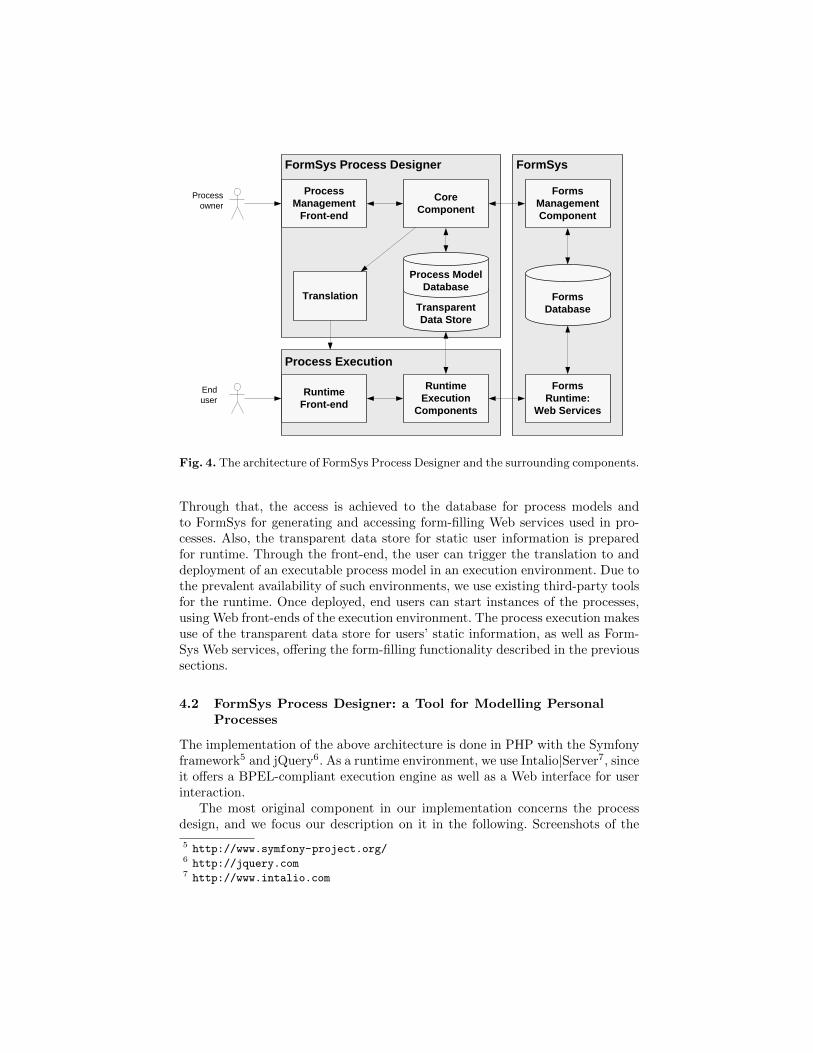
The architecture design for our solution is shown in Fig. 4. There are two userroles: process owner and end user. In terms of skills required, our goal is that theprocess owner can be a non-technical end user as well. However, he can sharethe deployed processes with peers or other users, so that they can make use ofthe implementation as well (role: End user).
The process owner designs the process model textually in a Web front-end. This front-end interacts with FormSys Process Designer’s core component.
4 https://www.cse.unsw.edu.au/~FormSys/process/, username ‘crc’ and password‘sdf2010’.
FormSysFormSys Process Designer
Core
Component
Forms
Management
Component
Translation
Process
Management
Front-end
Forms
Runtime:
Web Services
Process
owner
End
user
Forms
Database
Process Execution
Runtime
Front-end
Runtime
Execution
Components
Transparent
Data Store
Process Model
Database
Fig. 4. The architecture of FormSys Process Designer and the surrounding components.
Through that, the access is achieved to the database for process models andto FormSys for generating and accessing form-filling Web services used in pro-cesses. Also, the transparent data store for static user information is preparedfor runtime. Through the front-end, the user can trigger the translation to anddeployment of an executable process model in an execution environment. Due tothe prevalent availability of such environments, we use existing third-party toolsfor the runtime. Once deployed, end users can start instances of the processes,using Web front-ends of the execution environment. The process execution makesuse of the transparent data store for users’ static information, as well as Form-Sys Web services, offering the form-filling functionality described in the previoussections.
4.2 FormSys Process Designer: a Tool for Modelling PersonalProcesses
The implementation of the above architecture is done in PHP with the Symfonyframework5 and jQuery6. As a runtime environment, we use Intalio|Server7, sinceit offers a BPEL-compliant execution engine as well as a Web interface for userinteraction.
The most original component in our implementation concerns the processdesign, and we focus our description on it in the following. Screenshots of the
5 http://www.symfony-project.org/6 http://jquery.com7 http://www.intalio.com

Fig. 5. Textual process modelling in the FormSys Process Designer.
graphical user interface (GUI) can be seen in Figures 5-7. This Web-based GUIallows the user to specify valid PPML processes using a dynamic text-based(Fig. 5) or a visual (Fig. 6) modelling methodology.
In the textual editing mode (Fig. 5), a process model’s steps offer a fewfunctions by hovering with the mouse over the “+” symbol on the right-handside of a line. This opens a context menu where the chosen step can be removedor new steps can be added before or after it. The settings and values detailingprocess steps can be edited by clicking on the respective value. That opens upa drop-down box or a text field, depending on the field type. The mappings canbe edited in a similar fashion. Through the context menus, the user’s choices arelimited to valid changes in PPML, i.e., a valid model can only be changed sothat the resulting model is valid again.
In the visual editing mode (Fig. 6), all activities are represented with a thumb-nail image or an icon. Form-filling services are represented by a thumbnail of theform’s first page. The list of available activities is presented in a content flow (theblack area in Fig. 6), similar to cover flows in popular music library programs.The process designer can drag-and-drop activities from the content flow to theProcess Steps Workspace (the grey area in Fig. 6). Here the control flow of theprocess is expressed with arrows for sequencing (left to right, top to bottom);and dark-grey boxes for conditional execution, e.g., “if a residence statement isrequired”, the form contained in the respective box will be executed. Re-orderingsteps can be done by dragging-and-dropping them to a new position, includinginto and out of boxes with conditions.
Besides specifying the control flow, the process designer needs define the dataflow. As explained in the previous section, this means mapping input fields fromdifferent forms to each other (equality or concatenation), declaring static values

Fig. 6. Visual process modelling in the FormSys Process Designer.
for fields, or declaring fields as user-static. While the latter two features are notimplemented in the prototype yet, the former can be done textually, via drop-down menu selections (not shown), or visually (cf. Fig. 7). The user can definemappings between individual fields of forms by first dragging two forms fromthe Process Steps Workspace to the Mapping Workspace (in Fig. 7 this has beendone for Form 3000 and 4355 from the Queensland Driver License process), thenselecting “Add new mapping”, and then clicking on the fields in the forms thatare mapped to one another. This will colour the borders around those fields withthe colour of the mapping.
The list of declared mappings is shown as a list of squares in their coloursbelow the Add and Delete buttons on the top of the Mapping Workspace, and thesquare of the currently active mapping has a white fill. This list remains stablewhen replacing one or both of the forms in the Mapping Workspace. Hence, theuser can specify mappings of, e.g., the last name fields of more than two forms.When selecting more than one field for a mapping within one form (shown forthe dark purple mapping in Fig. 7), this is interpreted as concatenation of those

Fig. 7. Visual data mapping in the FormSys Process Designer.
two fields. This is indicated by the numbers shown inside the fields: the fieldslabelled “1” and “2” in the left-hand form are concatenated to a field labelled“1+2” in the right-hand form.
In addition to the model editor, there are overview pages for listing all avail-able processes, as well as allowing user administration and role assignment. Pro-cesses can also be viewed, instead of edited. This way, a process is presentedwithout the editing symbols, which results in a view that resembles Fig. 1 ratherclosely.
Process translation to BPEL can be triggered from the overview list. Thiscreates both a BPEL file and WSDL file containing the consolidated input andoutput message types, as described in Section 3.3. For process execution we usethe above-mentioned Intalio|Server. Hence, in addition to the BPEL and WSDLfiles, further artefacts are required: a deployment descriptor, an SVG graph of theprocess model in BPMN, and user interface pages (AJAX Web forms) for input(triggering a process instance) and output (viewing the results of the instance),and more. All these artifacts are automatically created when the translation isrequested. The result is a deployable package of the files, which can be uploadedto an Intalio|Server. A screenshot of an automatically created input Web formis shown in Fig. 8. It should be noted that, while usable as such, in real-worldusages most likely this form would most likely only form a starting point, andthe process designer would be allowed to change its design. Since the focus of this

work is not on UI generation, we only implemented this as a proof-of-conceptsolution.
5 Evaluation
After our analysis and implementation in the previous sections we provide afirst, small evaluation our work in this section with two case studies. The first isthe running example about applying a drivers license in Queensland. The secondis the travel and reimbursement process of the School of Computer Science andEngineering (CSE) of the University of New South Wales (UNSW). Both casestudies are real-world scenarios from large organizations. Nevertheless, they arestill form-based and to date no automation is offered to end users that areinvolved in these processes. In the following, we explain the processes, and howtheir implementation with FormSys and the FormSys Process Designer helps ineasing the burden for the end user. Subsequently we discuss our findings.
5.1 Case study 1: Queensland Drivers License Application
The license request or renewal process involves up to six forms an applicant hasto fill in. Which forms she has to fill in is described in a number of Web pages andhas to be understood before filling any form. As an example, an additional formhas to be filled if the the applicant has a medical condition. Furthermore, allforms request – among other things – the same personal information like name,address, date of birth and more. We analysed the process starting from the mainguideline8 and collected all forms. We upload the forms to FormSys and deploycorresponding Web Services for each of them. In the FormSys Process Designer,we then modelled the process (cf. Figures 5 and 6), mapped the data fields (cf.Fig. 7) and deployed the resulting process in Intalio|Server. The end user (citizen)can start the process through a Web page (cf. Fig. 8), where she enters therepetitive fields only once before starting an instance of the process. Additionallyshe answers the questions derived from the conditions of the process, accordingto which it will be determined which forms have to be filled. Depending on thisinformation, the process instance fills all forms or a just a subset of them, andreturns a message linking to the URLs where these forms are available. The usercan then print the forms and follow their instructions on where to submit them.
Specifying the control flow of this process was simple, once the instructionson the website were understood. The data flow mapping is not hard to do, asthe forms largely follow a common naming scheme. However, quite a few fieldshad to be mapped, where automatic mapping would have likely provided goodresults.
8 http://www.transport.qld.gov.au/Home/Licensing/Driver_licence/Getting_
a_licence/Car/Open_licence/

Fig. 8. Part of the input Web form to start the Queensland Driver Licence process.
5.2 Case study 2: CSE (UNSW) Travel Request and ReimbursementProcess
This case study is about the travel request and reimbursement of CSE, UNSW.Ignoring for this study the special cases of using a private car, getting a cash inadvance etc., a traveler has to fill three forms for each trip he wants to make:
– a request for a trip and total cost estimate;– a travel diary, listing the activities during the trip; and– a reimbursement request after the trip is finished.
We modelled the process using FormSys Process Designer, as shown in Fig. 9.In contrast to the other case study, this process is split in two parts. The requestis done before the trip and can lead to an early termination of the process whendenied. The second part is executed after the trip, and handles the reimburse-ment and travel dairy. After the approval, the process instance stops and waitsfor the manual task to be marked as completed. When the trip is finished, thetraveler confirms his return by marking the manual task as completed, and getsthe pre-filled reimbursement form and, depending on the nature of the trip (“if

Fig. 9. Textual process model of the UNSW travel process.
the trip is to a destination more than 100kms from the school”), also the dairyform. The data mapping for this process is partly shown in Fig. 10; its creationrequired less effort than for the first case study, mainly because only three formswere involved. However, the mapping was not as straight-forward.
5.3 Findings
We now discuss our findings regarding the prototype and our case studies. Weimplemented these real-world cases with our tool, to evaluate its suitability forsupporting personal processes. Each process’ control flow was created within afew minutes after the form-filling Web services were deployed through FormSys.From the tool side, a user familiar with assembling a music play-list should beable to design the control flow of a personal process in our tool. However, the userstill needs to have an understanding of how process models relate to instances.
The more effort-intensive part is the mapping: for forms with many fields orprocesses with many forms, the mapping consumes a significantly larger shareof time than the control flow modelling. Besides that, we think the concept ofbehind the data mapping may be confusing to non-technical users who are notfamiliar with process modelling methodologies in the first place, and may requiregood explanation.
After finishing a process model, deployment can be done automatically. In-talio executed all processes without problems. However, the presented Web in-terface for end user input to the processes is somewhat simplistic and offerspotential for improvement.

Fig. 10. Textual data mapping for the UNSW travel process.
6 Related Work
The introduction discussed the relation of this work to works on mash-upsand traditional business process execution or Web service orchestration. To ourknowledge, all related end-user process modelling tools do not feature the cre-ation of executable processes. We will discuss a number of these below.
Very recently, collaborative business process modelling for various types ofusers gained attention, e.g., [18, 19]. The relation to this work is that most ofthese approaches aim at collaborative discovery and re-design of processes, wherenon-IT-professionals and users without heavy training in process modelling arepart of the collaboration. We will discuss these approaches below.
Software AG offers the social networking BPM tool ARISalign9 [19]. Thefocus of this tool is to involve stakeholders and experts from within an organi-zation as well as outside in the process design. When the process design phaseis completed, the processes can be executed . SAP’s tool, Gravity [18], is a real-time collaborative process modelling environment and embedded in Google Waveand SAP 12sprint. There is a high-level modelling perspective (BPMN) and anexecutable level (proprietary notation, similar to Yahoo pipes). From the infor-mation available about the tool, the latter is primarily focused on widget-likeuser interfaces, but the tool also has a facility to send emails.
The company Lombardi10 has a tool called Blueprint, in which users cancollaboratively discover process models. The user, or group of users, starts bycreating a “process map”, which resembles Porter’s value chains. The map con-sists of a sequence of high-level steps, where more detailed process steps can beadded below each high-level step. The precise control flow can be designed inBPMN, and exported for further refinement to execution in Lombardi’s otherBPM tool, Teamworks 7. A strong feature of Blueprint is collaboration: userscan share, comment, update, and be notified about changes in process models.The focus is, however, again on BPM professionals discovering or improving coreprocesses.
A recent startup, Signavio11, offers a browser-based BPMN and value chainediting tool. The basis of this was the tool Oryx [20]. Again, a focus is oncollaboration, commenting, and sharing process models with others. Anotherfeature is a user-defined dictionary, to encourage similar naming of activities,documents, and other labels. The open-source project Activiti12 makes use ofSignavio’s modelling tool, so that BPMN models can be executed in the Activitienvironment. In relation to our solution, the Signavio Process Editor is quitesimilar to Lombardi’s Blueprint.
PICTURE is a domain-specific, building block-based modelling method andnotation [14, 15] for public administration. Out of a research project the com-pany PICTURE GmbH13 has been founded. The approach is based on a fixed,domain-specific set of modeling constructs: the building blocks. Example build-ing blocks are “receiving a document / information”, “coordinate / consult withother party”, or “execute formal check”. These can be named and further spec-ified, e.g., by stating the channels through which information is retrieved orwhich document is checked. Building blocks are arranged in sequences to formlocal subprocesses, and different subprocesses can be linked via so-called an-chors. Conditional execution can be expressed as different possible subprocessvariants. The argument for pure sequences in subprocesses is the same as inthis work: a single knowledge worker is expected to perform only one task atany given time[15]. In a real-world process consulting project, the PICTURE
9 http://www.arisalign.com/10 http://www.lombardisoftware.com/11 http://www.signavio.com/12 http://www.activiti.org13 http://www.picture-gmbh.de

method has been shown to offer significant higher efficiency in process discovery,e.g., a factor of five less time required in the two projects (one using eEPCs, theother PICTURE) compared in [15]. The reasons for the increasing efficiency area fixed level of abstraction, a terminology with which the process participantsare familiar, and the simplicity of the notation, according to the same source.PICTURE is a tool for discovering complete process landscapes in organizations,and not meant to design executable process models. However, we believe thatwe implemented the key features making process modelling simple and efficientin our approach as well, and thus hope to achieve the same advantages. The keydifference to our work is that PICTURE targets capturing the processes, anddoes not have any features to create executable processes.
Finally, there is the tool CoScripter (formerly called Koala) [21, 22]. Theprimary focus is on personal processes in the scope of browsing and using Webapplications. The user can record such browser processes, play them back, andsave them on a public Wiki. Other users can then make use of saved processes.The processes are stored in a simple end-user understandable language, usingnatural language keywords such as “ * go to <URL>” and “ * click on <link>”.Personal user information is stored in a personal database on the user’s machine.In the scenarios covered by this approach, the usefulness has been demonstratedby real users in their day-to-day work lives [21]. In contrast to our approachaiming at forms, the scope of CoScripter is limited to the browser: all steps in ascript need to be standard operations in a browser window. While closely relatedto our work in terms of the textual process representation and the end user focus,it does not support Web service invocation or conditional execution. We plan onintegrating CoScripter scripts as another type of activity in our personal processmodelling environment in our future work.
7 Conclusion
In this report we present the current status of our research and prototype de-velopment on personal process management. With the solution discussed, endusers can assemble executable counterparts of their form-based processes, whichcan significantly reduce the amount of redundant data entry required for thoseprocesses. The current status poses a first milestone, and has been shortly eval-uated with two case studies. These case studies uncovered some weaknesses,which we will work on in the mid-term future, first and foremost support forsemi-automatic data mapping.
More long-term future work will focus on the following: (i) including othertypes of services, including WSDL/SOAP, RESTful Web services, etc., at thecost of requiring a more complete solution for data flow; and (ii) more flexibleexecution, so that users can roll-back process instances, e.g., to change someinput values, and re-execute selected steps.

References
1. Davenport, T.H., Short, J.E.: The New Industrial Engineering: Information Tech-nology and Business Process Redesign. MIT Sloan Management Review 31(4)(1990) 11–27
2. Richardson, C., Vollmer, K., Clair, C.L., Moore, C., Vitti, R.: Business ProcessManagement Suites, Q3 2009 – The Need For Increased Business Agility DrivesBPM Adoption. Forrester TechRadar For BP&A Pros (13 August 2009)
3. Leymann, F., Roller, D.: Production Workflow - Concepts and Techniques. PrenticeHall (2000)
4. Schurter, T.: BPM state of the nation 2009. bpm.com, http://www.bpm.com/
bpm-state-of-the-nation-2009.html (2009) Accessed 25/11/2009.5. Oracle White Paper: State of the business process management
market 2008. http://www.oracle.com/technologies/bpm/docs/
state-of-bpm-market-whitepaper.pdf, accessed 20/11/2009 (August 2008)6. Wolf, C., Harmon, P.: The state of business process management. Technical report,
BPTrends (June 2006) http://www.bptrends.com/.7. Ogrinz, M.: Mashup Patterns: Designs and Examples for the Modern Enterprise.
Addison-Wesley Professional (March 2009)8. Wong, J., Hong, J.: What do we ”mashup” when we make mashups? In:
WEUSE’08: 4th International Workshop on End-user Software Engineering atICSE’08, Leipzig, Germany. (May 2008)
9. Yu, J., Benatallah, B., Casati, F., Daniel, F.: Understanding mashup development.IEEE Internet Computing 12(5) (2008) 44–52
10. Weber, I., Paik, H., Benatallah, B., Gong, Z., Zheng, L., Vorwerk, C.: FormSys:Form-processing web services. In: WWW’10: Proceedings of the 19th InternationalWorld Wide Web Conference, Demo Track. (2010) http://imweber.de/texte/
FormSys-Form-processingWebServices--WWW2010--authors_copy.pdf.11. Adobe Systems Incorporated: Acrobat Forms API Reference (2003) Technical Note
No. 5181.12. van der Aalst, W., ter Hofstede, A.H.M., Kiepuszewski, B., Barros, A.P.: Workflow
patterns. Distributed and Parallel Databases 14(1) (2003) 5–5113. zur Muehlen, M., Recker, J.: How much language is enough? theoretical and prac-
tical use of the business process modeling notation. In: CAiSE’08: 20th Inter-national Conference on Advanced Information Systems Engineering, Montpellier,France (June 2008)
14. Becker, J., Pfeiffer, D., Rackers, M.: PICTURE - a new approach for domain-specific process modelling. In: CAiSE Forum. (2007)
15. Becker, J., Algermissen, L., Pfeiffer, D., Rackers, M.: Bausteinbasierte Model-lierung von Prozesslandschaften mit der PICTURE-Methode am Beispiel der Uni-versitatsverwaltung Munster. Wirtschaftsinformatik 49 (2007) 267–279
16. Do, H.H., Rahm, E.: COMA – a system for flexible combination of schema match-ing approaches. In: VLDB’02: 28th Intl. Conference on Very Large Databases.(2002)
17. Drumm, C., Schmitt, M., Do, H.H., Rahm, E.: Quickmig - automatic schemamatching for data migration projects. In: CIKM’07: 16th ACM Conference onInformation and Knowledge Management. (2007)
18. Balko, S., Dreiling, A., Fleischmann, K., Hettel, T.: Gravity – collaborative busi-ness process modelling and application development. SAP Community Network,http://www.sdn.sap.com/irj/scn/weblogs?blog=/pub/wlg/17826 (23 February2010)

19. Sayer, P.: Software ag opens bpm social networking beta test. PCWorld BusinessCenter, http://www.pcworld.com/businesscenter/article/190592/software_
ag_opens_bpm_social_networking_beta_test.html (2 March 2010)20. Decker, G., Overdick, H., Weske, M.: Oryx – an open modeling platform for the
BPM community. In: Demonstrations at BPM’08: 6th International Conferenceon Business Process Management. (2008)
21. Leshed, G., Haber, E., Matthews, T., Lau, T.: Coscripter: Automating & sharinghow-to knowledge in the enterprise. CHI Letters: Human Factors in ComputingSystems 10(1) (2008) 1719–1728
22. Little, G., Lau, T., Cypher, A., Lin, J., Haber, E., Kandogan, E.: Koala: Capture,share, automate, personalize business processes on the web. CHI Letters: HumanFactors in Computing Systems 9(1) (2007) 943–946