personal full electric vehicle picav: non linear dynamic ... · pdf filecars and...
TRANSCRIPT

Abstract— Request of sustainable personalized transport is
growing in different areas of service robotics, for aid to mobility of
elderly and motion disabled people, for freight delivery in urban
environment, for passengers transport in restricted zones as airports
and greens because of the small dimensions, tiny footprint, on-board
intelligence, friendly human car interface and zero environmental
impact. The paper studies the feasibility of an electric vehicle with
four non steering wheels considering as driving principle the skid
steering that has been mainly used for tracked vehicles.The vehicle is
a complex nonlinear multi body system with numerous mobilities
either in stiff and in elastic motion. For evaluating the vehicle
performances, the maneuverability and stability behavior it is needed
the availability of a model able to describe all the significant motion
modes in different operative conditions. The paper presents the
PICAV model and some results of the simulation campaign that
demonstrated its soundness and reliability.
Keywords— Full electric vehicle, Dynamic model,
Manouvrability behavior, Simulation.
I. INTRODUCTION
OBILITY and communication are markers of civilised
society level: the restrictions on people or ideas always
mean dark seasons. Sustainable development, however,
requires today compatibility checks, with emphasis for highly
pedestrianized areas. Many technical developments ought to
be reconsidered, possibly, rethinking solutions accepted as
obvious, that actually lay within the range of habits [1]. City-
cars and personal-movers are example case, where innovations
and non-conventional ideas have to be weighed to look after
effectiveness. The paper refers to a new mobility concept for
passengers ensuring accessibility for all in urban pedestrian
environments and proposes a detailed dynamic model and
simulation used for the vehicle design and control. The
concept addresses a new Personal Intelligent City Accessible
Vehicle (PICAV) and a new transport system that integrates a
fleet of PICAV units. The transport system will ensure safe
and secure accessibility for everybody [2], [3] and some of its
This work was supported in part by the European Commission through the
PICAV project funded under the Seventh Framework Program (Collaborative
Project SCPS-GA -2009-233776).
F. Cepolina was with DIME University of Genoa, Italy ( e-mail:
fcepolina@ hotmail.com).
E:M:. Cepolina is with the Department of DICI, University of Pisa, Pisa,
Italy (e-mail: [email protected]).
features are specifically designed for people whose mobility is
restricted for different reasons, particularly (but not only)
elderly and disabled people. Ergonomics, comfort, stability,
assisted driving, eco-sustainability, parking and mobility
dexterity as well as vehicle/infrastructures intelligent
networking are the main drivers of PICAV design. The
innovative electrical vehicle will present new frame-
suspension structure, new seating sub-assembly, new efficient
power supply module.
The PICAV transport system will provide an efficient and
rational service to citizens within urban areas where traffic is
restricted: the application fields of PICAV are pedestrianised
areas, ‘shared space’ areas (where vehicles are allowed, but
where the same space is shared between vehicles and
pedestrians), pedestrian environments where conventional
public transport services cannot operate because of the width
and slope of the infrastructures, uneven pavements and the
interactions with high pedestrian flows and indoor pedestrian
areas (e.g. shopping malls). The vehicle because of its small
size, tiny footprint, on-board intelligence and zero
environmental impact is suitable for moving in these areas and
it behaves almost as a pedestrian, disturbing other pedestrians
as little as possible. Therefore the PICAV system usefully
integrates the existing public transport system to help it
become more accessible for older and disabled people by
acting as a smooth link between walking, bicycle and
conventional public transport and thus extending the
availability of a public motorised transport service to cover the
entire urban area.
These vehicles are developed for local traffic duty, worth
for low speed and bounded autonomy; several auto-makers are
becoming aware of the challenge [4], still the offers do not
turn out from to many conventional technicalities. PICAV, Fig.
1, is a small electric motorised vehicle, able to follow paths
and slopes, with given performance (payload, speed,
acceleration, autonomy, etc.). Transport systems for pedestrian
areas, based on a fleet of semiautonomous or fully-automated
PICAVs have been proposed in [5], [6] and [7]. The paper
reconsiders the driving and manoeuvrability operations,
assuming four independently powered wheels [8], [9], [10].
The investigation builds up the vehicle dynamics moving from
the behaviour of a driving wheel (with compliant tyre);
R. Molfino is with Department of Department of Mechanical, Energetics,
Management and Transport Engineering , University of Genoa, Italy (phone:
+390103532842; fax: +390103532298; e-mail: [email protected]).
Personal full electric vehicle PICAV: non linear
dynamic model and simulation
F. Cepolina, E.M. Cepolina, R.M. Molfino
M
INTERNATIONAL JOURNAL OF MATHEMATICAL MODELS AND METHODS IN APPLIED SCIENCES Volume 9, 2015
ISSN: 1998-0140 518

modelling the group motor wheel suspension and then
assembling the four groups to the chassis to find out the
motion of the centroid and around it when the four actuators
operate while the vehicle moves on varying soil surfaces.
The dynamic model written in the general case of six degrees
of freedom vehicle with four motorized steering wheels has
been presented [11]. Here the dynamic model of PICAV with
no steering wheels is proposed.
Legenda Symbol Value
Total mass M 400 kg
Height of the center of gravity rGz 0.58 m
Wheel rolling radius R 0.2 m
Wheel moment of inertia I 0.1kgm2
Fig. 1 PICAV FIRST digital mock-up (courtesy Aazir Khan) and
main parameters
The actuation redundancy makes these models complex,
but, at the same time, opens new opportunities, on condition
that proper information is exploited. An interesting
opportunity is to exploit the actuation torque supplied by each
motor and the speed of the individual wheels, to reckon the
useful traction force required at soil-tyre interfaces, once the
adherence and creeping condition are assessed [12]. From the
analysis performed by researchers in the field, has been shown
that a four independent motor wheels vehicle can be driven
along any path by simply controlling the slip, without
necessarily impressing a turning angle to the wheels. On these
premises, the manoeuvre dexterity and stability are considered
the main performances for all the tasks a city vehicle is
required to perform at low speed over urban roads [10].
II. DYNAMIC MODEL OF PICAV
The study deals with electrically powered personal vehicles,
used to transport one person with limited autonomy range
(some 60 km), at low speed (max 25 km/h), assuming proper
soil upkeep. The four wheels are individually actuated, but the
driver, as usual, acts on two commands: steering and
acceleration, while the controller needs modify the torque and
the speed, so that the (four) soil/tyre interfaces grant the
required manoeuvrability and stability [13]. The problem is
consistent, by itself, with several issues, on condition that the
vehicle dynamics is modelled with account of the pertinent
degrees of freedom [14].
Quite often, indeed, the reference models are limited to
‘quarter car’ or to ‘bicycle’ cases, totally or partially
neglecting roll and pitch motion. In this case, due to the
PICAV special aim to guarantee the accessibility to city
centers to all, including elders and mobility impaired people,
stability and manoeuvrability are the main issues [15], [16]. So
detailed reliable models are needed as a base for the vehicle
mechatronic design and real time control system set-up.
The vehicle is modelled as a multi bodies system: the
chassis connected, through viscous-elastic joints, to four
masses including suspensions and motorised wheels, each one
coupled with the road.
The basic modules involved in the analysis are indicated in
the Fig. 2. Due to the low speed and the comparatively smooth
soil, finally, a 14-degrees-of-freedom model is obtained: 6 for
the car body (3 of the centroid and 3 around it); 2 for each of
the four suspended masses (the linear motion at joints and the
rotation of the wheels); namely, in body-axes and assuming
small angular deflections, the reference dynamics is set, as in
the following sections.
23
Chassis dynamicseq.(3)-(4)
Wheel
Tyre-soilcontacteq.(10)-(14)
Motor-wheelmodeleq.(7)-(8)-(9)
Elastic suspen-sion modeleq.(5)-(6)
Chassisforcesonwheel
1Wheel
Tyre-soilcontacteq.(10)-(14)
Motor-wheelmodeleq.(7)-(8)-(9)
Elastic suspen-sion modeleq.(5)-(6)
Chassisforcesonwheel
4Wheel
Wheel
Fig. 2 Modular view of the 4 wheels vehicle model.
The basic reference frames are shown in Fig. 3a
i'
i'' i'''
j'''
k'''
j' j''
e3 k'
k''
e2
e1
i wh
i ch
jwh
jch
e2
e1
(a)
iO
G
x
y
FxiFyi
rxiryiri
e1
e2
(b) Fig.3 (a) Co-ordinate frames, (b) Wheel chassis outline.
INTERNATIONAL JOURNAL OF MATHEMATICAL MODELS AND METHODS IN APPLIED SCIENCES Volume 9, 2015
ISSN: 1998-0140 519

The symbols in Fig. 3 refer to: roll (), pitch (), yaw () and
steering () angles for basic rotations; the subscript ch refers to the
chassis, wh refers to the wheel, {e1, e2, e3} is the fixed frame. These
frames and angles refer to the general vehicle model. In the case of
PICAV (no steering wheels) = and {i’ j’ k’}ch≡{i’ j’ k’}wh,
The rotation transformation from the fixed to the mobile reference
is:
rollpitchyawypr RRRR (1)
The angular acceleration on the mobile reference frame, attached
to the chassis,is:
(2)
A. The chassis model
The chassis is considered as a rigid body with 6 degrees of
freedom. The reference frames are shown in Fig. 3.
The dynamic model of the chassis has been written in [11]
in the chassis reference frame, in the case of wheels null
camber and chassis inertia diagonal matrix. This model is
hyper static and difficult to solve in the general case. In the
case of PICAV it is admitted that the suspension stiffness is
very high so that roll and pitch motions can be neglected
((. Further, considering that PICAV has no steering
wheels, = the simplified model is: 4
1
4
1
4
1
0
xi
i
Gx Gy
yi ch Gy ch Gx
i
Gz
zi ch
i
F
a v
F m a m v
a
F m g
(3)
4
1 1 1 1 2 2 2 2 3 3 3 3 4 4 4 4
1
4
1 1 1 1 2 2 2 2 3 3 3 3 4 4 4 4
1
4
1 1 1 1 2 2 2 2 3 3 3 3 4 4 4 4
1
y z z y y z z y y z z y y z z y xi
i
z x x z z x x z z x x z z x x z yi
i
x y y x x y y x x y y x x y y x zi
i
r F r F r F r F r F r F r F r F M
r F r F r F r F r F r F r F r F M
r F r F r F r F r F r F r F r F M
0
0
zchI
(4)
Where Izch is the inertia of the chassis about z axis; mch is
the chassis mass; [rx, ry, rz]Tk is the arm vector of the force
Fk= [Fx, Fy, Fz]Tk applied to the chassis from the group
suspension motor wheel k. Mi= [Mx, My, Mz]Ti is the vector
moment applied to the chassis from the ith
suspension motor
wheel group.
B. Motor-wheel-suspension group
The schema of the suspensions and terminology are given in
Fig.4.
Fig.4 Schema of the visco-elastic elements between the road and
the vehicle body (chassis); 1 and 3 indicate the left side wheels, 2 and
4 indicate the right side wheels, 1 and 2 are front wheels
The proposed dynamic model of the individual suspension
is:
2
2
whx x Gx GSy GSx
why y susp Gy GSx GSy
whz z susp s susp s s
F F a r r
F F m a r r
F F c z k z z
(5
suspwhzz
ywhxs
whxxwhys
IMM
MFz
MMFz
0
0
(6)
where is the yaw angle, Fwh and Mwh are force and
moment due to the motor wheel; msusp and Isusp are the mass
properties of the suspension, ksusp and csusp are the elastic
and damping parameters of the suspensions; zs is the quote of
the suspension mass msusp considered concentrated; r’GS is
the vector between the chassis center of mass G and the
suspension contact point S where the suspension is linked to
the chassis; aG is the G acceleration; the superscript indicates
the reference frame {i’, j’, k’}. A detailed model and Simulink
scheme of suspensions is given in [17]
In the case of stiff suspensions the vertical acceleration is
zero: 0sz .
The motor wheel dynamic model considers all the degrees
of freedom supplied from the rotations around three non
orthogonal axes: spin around the current y axis (j),
corresponding to spinning torque Ms, steering around the z
fixed axis (e3), corresponding to steering torque Mst, camber
around the current x axis (i), corresponding to camber torque
Mc, see Fig. 5. R= [Rx, Ry, Rz]T is the road reaction on the
tyre and Fwh is the force applied by the chassis suspension to
the wheel.
Mc
k' e3
i '
Fx
Fy
j '
k
j
i
Fz
Ms Ms
Ms
Ms
Fig.5 Motor-wheel sketch
The motor wheel dynamic model is derived in the
general case in [11].
s c
c s c s s s c c
c c s c c s s c
INTERNATIONAL JOURNAL OF MATHEMATICAL MODELS AND METHODS IN APPLIED SCIENCES Volume 9, 2015
ISSN: 1998-0140 520
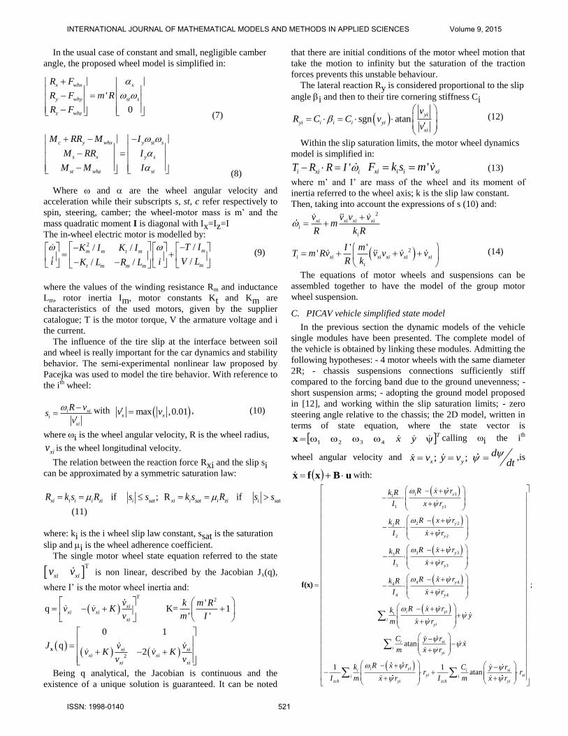
In the usual case of constant and small, negligible camber
angle, the proposed wheel model is simplified in:
'
0
x whx s
y why st s
z whz
R F
R F m R
R F
(7)
c y whx y st s
s x y s
st whz st
M RR M I
M RR I
M M I
(8)
Where and are the wheel angular velocity and
acceleration while their subscripts s, st, c refer respectively to
spin, steering, camber; the wheel-motor mass is m’ and the
mass quadratic moment I is diagonal with Ix=Iz=I
The in-wheel electric motor is modelled by: 2 // /
// /
mm m t m
mt m m m
T IK I K I
V Li iK L R L
(9)
where the values of the winding resistance Rm and inductance
Lm, rotor inertia Im, motor constants Kt and Km are
characteristics of the used motors, given by the supplier
catalogue; T is the motor torque, V the armature voltage and i
the current.
The influence of the tire slip at the interface between soil
and wheel is really important for the car dynamics and stability
behavior. The semi-experimental nonlinear law proposed by
Pacejka was used to model the tire behavior. With reference to
the ith
wheel:
i xii
xi
R vs
v
with max ,0.01x xv v ,
(10)
whereiis the wheel angular velocity, R is the wheel radius,
xiv is the wheel longitudinal velocity.
The relation between the reaction force Rxi and the slip si
can be approximated by a symmetric saturation law:
if ; R if xi i i i zi i sat xi i sat i zi i satR k s R s s k s R s s
(11)
where: ki is the i wheel slip law constant, ssat is the saturation
slip and i is the wheel adherence coefficient.
The single motor wheel state equation referred to the state
T
xi xiv v is non linear, described by the Jacobian Jx(q),
where I’ is the motor wheel inertia and:
2
2
'q K= 1
' '
0 1
q2
T
xixi xi
xi
xi xixi xi
xi xi
v k m Rv v K
v m I
J v vv K v K
v v
x
Being q analytical, the Jacobian is continuous and the
existence of a unique solution is guaranteed. It can be noted
that there are initial conditions of the motor wheel motion that
take the motion to infinity but the saturation of the traction
forces prevents this unstable behaviour.
The lateral reaction Ry is considered proportional to the slip
angle i and then to their tire cornering stiffness Ci
sgn atanyi
yi i i i yi
xi
vR C C v
v
(12)
Within the slip saturation limits, the motor wheel dynamics
model is simplified in:
'i xi iT R R I ' xi i i xiF k s m v (13)
where m’ and I’ are mass of the wheel and its moment of
inertia referred to the wheel axis; k is the slip law constant.
Then, taking into account the expressions of s (10) and: 2
xi xi xi xii
i
v v v vm
R k R
2' ''i xi xi xi xi xi
i
I mT m Rv v v v v
R k
(14)
The equations of motor wheels and suspensions can be
assembled together to have the model of the group motor
wheel suspension.
C. PICAV vehicle simplified state model
In the previous section the dynamic models of the vehicle
single modules have been presented. The complete model of
the vehicle is obtained by linking these modules. Admitting the
following hypotheses: - 4 motor wheels with the same diameter
2R; - chassis suspensions connections sufficiently stiff
compared to the forcing band due to the ground unevenness; -
short suspension arms; - adopting the ground model proposed
in [12], and working within the slip saturation limits; - zero
steering angle relative to the chassis; the 2D model, written in
terms of state equation, where the state vector is
Tyx 4321x calling i the i
th
wheel angular velocity and ; ; x y
dx v y vdt
,is
uBxfx with:
1 11
1 1
2 22
2 2
3 33
3 3
4 44
4 4
atan
y
y
y
y
y
y
y
y
i yii
iyi
i xi
R x rk R
I x r
R x rk R
I x r
R x rk R
I x r
R x rk R
I x r
R x rky
m x r
C y r
m
f(x)
;
1 1atan
iyi
i yii i xiyi xii i
zch yi zch yi
xx r
R x rk C y rr r
I m x r I m x r
INTERNATIONAL JOURNAL OF MATHEMATICAL MODELS AND METHODS IN APPLIED SCIENCES Volume 9, 2015
ISSN: 1998-0140 521

1
2
1
2
3
3
44
10 0 0
10 0 0
10 0 0
= ; =
10 0 0
0 0 0 0
0 0 0 0
0 0 0 0
I
IT
TI
T
TI
B u
(15)
As derived in [11] where: Tj, is the actuation torque reduced
at each wheel axis and subscripts 1÷4 refer to the wheels. The
model is non-linear and includes dynamic couplings in f(x).
This state model can be used in model based PICAV control
systems [16] while it is too simplified to represent the dynamic
behaviour of the vehicle in real operative conditions.
To check the feasibility of practical manoeuvres the
equations of the modelled dynamics have to be solved and a
suitable simulator has been written using Matlab/Simulink, and
resorting to a library purposely written for vehicle dynamics,
by fully exploiting the modelling modular approach. In the
PICAV dynamics simulation the external aerodynamic forces
were neglected due to the PICAV low velocity.
III. SIMULATION RESULTS
The models of the single bodies of the vehicle have been
codified in Simulink modules, that suitably linked as in Fig.6
give the virtual dynamic mock-up of the PICAV
vehicle.
Fig. 6 Sketch of the PICAV dynamic model in Simulink
The vehicle PICAV is designed with not standard
architecture suitably thought for weak, elderly and motion
impaired people to move even in difficult city centers grounds,
so the detailed dynamic model is considered a knowledge base
necessary for the analysis of the motion behaviour and for the
safety measure in terms of the manoeuvrability and stability
that represent the main concern for this kind of vehicle.
The models derived in the previous section can be used for
knowing the direct dynamic behaviour of the vehicle for
manoeuvring, stability checks and design purposes as
presented in Fig. 7. In case of vehicle semi-automatic open
loop (driving assistant) [10], [17] or closed loop autonomous
[15], [19] use the derived models can be used as described in
the same Fig. 7.
Fig. 7 Main I/O in the vehicle dynamics
The PICAV model and simulator were validated stand alone
in different operative and environmental conditions. The most
critical module is the motor wheel module: tests with braking
and accelerating torques with different adherence conditions,
with transversal force application, helped to be confident in the
model describing the interaction of the motor wheel and the
environment. Some results of the recalled simulation
experiments are shown in [7].
A. PICAV on circular trajectory
The motion along a circular path is characterized by
constant yaw velocity and therefore zero acceleration due to
the equilibrium between the torques generated by the
transversal and longitudinal reactions.
In Fig. 8 are shown the results obtained applying on the
outer train 20 Nm torques and on the inner one 1.2 Nm
torques, the reference trajectory is a 64 m radius circle. During
this trajectory the chassis yaw is decreasing with constant
speed and zero acceleration. Fig.9 and Fig.10 depict the trends
of significant variables during this manoeuvre: the forces
exchanged between soil and wheels, the forces applied from
the wheels to the chassis. The results highlighted that the slip
angles on the front wheels are inferior to the rear wheels slip
angles resulting in a lightly oversteering behaviour. This is
understandable because each wheel velocity is determined by
the sum of the velocity of the vehicle center of mass plus the
velocity due to the vehicle rotation.
INTERNATIONAL JOURNAL OF MATHEMATICAL MODELS AND METHODS IN APPLIED SCIENCES Volume 9, 2015
ISSN: 1998-0140 522
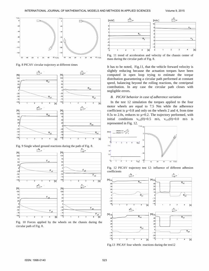
Fig. 8 PICAV circular trajectory at different times
Fig. 9 Single wheel ground reactions during the path of Fig. 8.
Fig. 10 Forces applied by the wheels on the chassis during the
circular path of Fig. 8.
Fig. 11 trend of acceleration and velocity of the chassis center of
mass during the circular path of Fig. 8.
It has to be noted, Fig.11, that the vehicle forward velocity is
slightly reducing because the actuation torques have been
computed in open loop trying to estimate the torque
distribution guaranteeing a circular path performed at constant
speed, balancing beyond the rolling reactions, the centripetal
contribution. In any case the circular path closes with
negligible errors.
B. PICAV behavior in case of adherence variation
In the test 12 simulation the torques applied to the four
motor wheels are equal to 7.5 Nm while the adherence
coefficient is µ=0.8 and only on the wheels 2 and 4, from time
0.5s to 2.0s, reduces to µ=0.2. The trajectory performed, with
initial conditions vGx(0)=0.5 m/s, vGY(0)=0.0 m/s is
represented in Fig. 12.
Fig. 12 PICAV trajectory test 12: influence of different adhesion
coefficients
Fig.13 PICAV four wheels reactions during the test12
INTERNATIONAL JOURNAL OF MATHEMATICAL MODELS AND METHODS IN APPLIED SCIENCES Volume 9, 2015
ISSN: 1998-0140 523
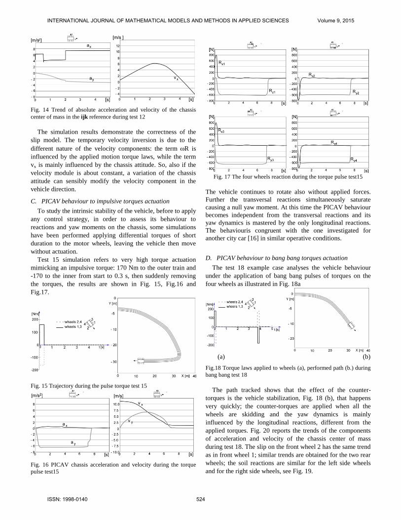
Fig. 14 Trend of absolute acceleration and velocity of the chassis
center of mass in the ijk reference during test 12
The simulation results demonstrate the correctness of the
slip model. The temporary velocity inversion is due to the
different nature of the velocity components: the term R is
influenced by the applied motion torque laws, while the term
vx is mainly influenced by the chassis attitude. So, also if the
velocity module is about constant, a variation of the chassis
attitude can sensibly modify the velocity component in the
vehicle direction.
C. PICAV behaviour to impulsive torques actuation
To study the intrinsic stability of the vehicle, before to apply
any control strategy, in order to assess its behaviour to
reactions and yaw moments on the chassis, some simulations
have been performed applying differential torques of short
duration to the motor wheels, leaving the vehicle then move
without actuation.
Test 15 simulation refers to very high torque actuation
mimicking an impulsive torque: 170 Nm to the outer train and
-170 to the inner from start to 0.3 s, then suddenly removing
the torques, the results are shown in Fig. 15, Fig.16 and
Fig.17.
Fig. 15 Trajectory during the pulse torque test 15
Fig. 16 PICAV chassis acceleration and velocity during the torque
pulse test15
Fig. 17 The four wheels reaction during the torque pulse test15
The vehicle continues to rotate also without applied forces.
Further the transversal reactions simultaneously saturate
causing a null yaw moment. At this time the PICAV behaviour
becomes independent from the transversal reactions and its
yaw dynamics is mastered by the only longitudinal reactions.
The behaviouris congruent with the one investigated for
another city car [16] in similar operative conditions.
D. PICAV behaviour to bang bang torques actuation
The test 18 example case analyses the vehicle behaviour
under the application of bang bang pulses of torques on the
four wheels as illustrated in Fig. 18a
(a) (b)
Fig.18 Torque laws applied to wheels (a), performed path (b.) during
bang bang test 18
The path tracked shows that the effect of the counter-
torques is the vehicle stabilization, Fig. 18 (b), that happens
very quickly; the counter-torques are applied when all the
wheels are skidding and the yaw dynamics is mainly
influenced by the longitudinal reactions, different from the
applied torques. Fig. 20 reports the trends of the components
of acceleration and velocity of the chassis center of mass
during test 18. The slip on the front wheel 2 has the same trend
as in front wheel 1; similar trends are obtained for the two rear
wheels; the soil reactions are similar for the left side wheels
and for the right side wheels, see Fig. 19.
INTERNATIONAL JOURNAL OF MATHEMATICAL MODELS AND METHODS IN APPLIED SCIENCES Volume 9, 2015
ISSN: 1998-0140 524
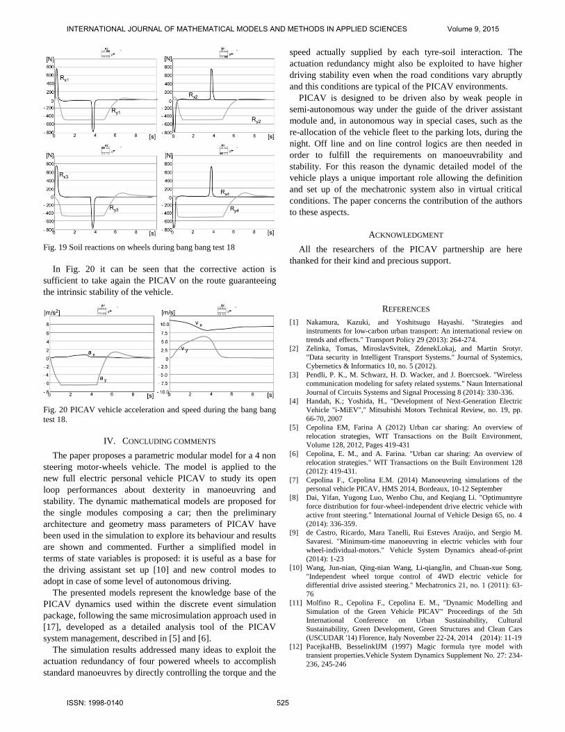
Fig. 19 Soil reactions on wheels during bang bang test 18
In Fig. 20 it can be seen that the corrective action is
sufficient to take again the PICAV on the route guaranteeing
the intrinsic stability of the vehicle.
Fig. 20 PICAV vehicle acceleration and speed during the bang bang
test 18.
IV. CONCLUDING COMMENTS
The paper proposes a parametric modular model for a 4 non
steering motor-wheels vehicle. The model is applied to the
new full electric personal vehicle PICAV to study its open
loop performances about dexterity in manoeuvring and
stability. The dynamic mathematical models are proposed for
the single modules composing a car; then the preliminary
architecture and geometry mass parameters of PICAV have
been used in the simulation to explore its behaviour and results
are shown and commented. Further a simplified model in
terms of state variables is proposed: it is useful as a base for
the driving assistant set up [10] and new control modes to
adopt in case of some level of autonomous driving.
The presented models represent the knowledge base of the
PICAV dynamics used within the discrete event simulation
package, following the same microsimulation approach used in
[17], developed as a detailed analysis tool of the PICAV
system management, described in [5] and [6].
The simulation results addressed many ideas to exploit the
actuation redundancy of four powered wheels to accomplish
standard manoeuvres by directly controlling the torque and the
speed actually supplied by each tyre-soil interaction. The
actuation redundancy might also be exploited to have higher
driving stability even when the road conditions vary abruptly
and this conditions are typical of the PICAV environments.
PICAV is designed to be driven also by weak people in
semi-autonomous way under the guide of the driver assistant
module and, in autonomous way in special cases, such as the
re-allocation of the vehicle fleet to the parking lots, during the
night. Off line and on line control logics are then needed in
order to fulfill the requirements on manoeuvrability and
stability. For this reason the dynamic detailed model of the
vehicle plays a unique important role allowing the definition
and set up of the mechatronic system also in virtual critical
conditions. The paper concerns the contribution of the authors
to these aspects.
ACKNOWLEDGMENT
All the researchers of the PICAV partnership are here
thanked for their kind and precious support.
REFERENCES
[1] Nakamura, Kazuki, and Yoshitsugu Hayashi. "Strategies and
instruments for low-carbon urban transport: An international review on
trends and effects." Transport Policy 29 (2013): 264-274.
[2] Zelinka, Tomas, MiroslavSvitek, ZdenekLokaj, and Martin Srotyr.
"Data security in Intelligent Transport Systems." Journal of Systemics,
Cybernetics & Informatics 10, no. 5 (2012).
[3] Pendli, P. K., M. Schwarz, H. D. Wacker, and J. Boercsoek. "Wireless
communication modeling for safety related systems." Naun International
Journal of Circuits Systems and Signal Processing 8 (2014): 330-336.
[4] Handah, K.; Yoshida, H., "Development of Next-Generation Electric
Vehicle "i-MiEV"," Mitsubishi Motors Technical Review, no. 19, pp.
66-70, 2007
[5] Cepolina EM, Farina A (2012) Urban car sharing: An overview of
relocation strategies, WIT Transactions on the Built Environment,
Volume 128, 2012, Pages 419-431
[6] Cepolina, E. M., and A. Farina. "Urban car sharing: An overview of
relocation strategies." WIT Transactions on the Built Environment 128
(2012): 419-431.
[7] Cepolina F., Cepolina E.M. (2014) Manoeuvring simulations of the
personal vehicle PICAV, HMS 2014, Bordeaux, 10-12 September
[8] Dai, Yifan, Yugong Luo, Wenbo Chu, and Keqiang Li. "Optimumtyre
force distribution for four-wheel-independent drive electric vehicle with
active front steering." International Journal of Vehicle Design 65, no. 4
(2014): 336-359.
[9] de Castro, Ricardo, Mara Tanelli, Rui Esteves Araújo, and Sergio M.
Savaresi. "Minimum-time manoeuvring in electric vehicles with four
wheel-individual-motors." Vehicle System Dynamics ahead-of-print
(2014): 1-23
[10] Wang, Jun-nian, Qing-nian Wang, Li-qiangJin, and Chuan-xue Song.
"Independent wheel torque control of 4WD electric vehicle for
differential drive assisted steering." Mechatronics 21, no. 1 (2011): 63-
76
[11] Molfino R., Cepolina F., Cepolina E. M., "Dynamic Modelling and
Simulation of the Green Vehicle PICAV" Proceedings of the 5th
International Conference on Urban Sustainability, Cultural
Sustainability, Green Development, Green Structures and Clean Cars
(USCUDAR '14) Florence, Italy November 22-24, 2014 (2014): 11-19
[12] PacejkaHB, BesselinkIJM (1997) Magic formula tyre model with
transient properties.Vehicle System Dynamics Supplement No. 27: 234-
236, 245-246
INTERNATIONAL JOURNAL OF MATHEMATICAL MODELS AND METHODS IN APPLIED SCIENCES Volume 9, 2015
ISSN: 1998-0140 525

[13] Scott, Ryan. "The Dynamics and Control of Independent Wheel Drive
Electric Vehicles." PhD diss., 2014
[14] Will AB, Zak SH (1997) Modelling and control of an automated
vehicle. Vehicle System Dynamics No. 27: 131-155
[15] Gasbaoui, Brahim, Abdelfatah NASRI, Moustapha RAHLI, and
Abdelkader CHAKER. "An Intelligent PI Speed Controller for 4WD
Urban Electric Vehicle." Electrotehnica, Electronica, Automatica 62,
no. 2 (2014).
[16] Michelini R.C., Molfino R.M., Ghigliazza R., Callegari M., The Tyre-
Soil Effects on the Manoeuvrability of a City-Car, 2001 IEEE/ASME
Int. Conf. on Advanced Intelligent Mechatronics, 8-12 July 2001,
Como, Italy
[17] Popescu Marius-Constantin, Mastorakis Nikos E. « Testing and
Simulation of a Motor Vehicle Suspension » International Journal of
Systems Applications, Engineering & Development, Issue 2, Volume 3,
2009
[18] Cepolina, Elvezia M., and Nick Tyler. "Microscopic simulation of
pedestrians in accessibility evaluation." Transportation planning and
technology 27, no. 3 (2004): 145-180.
[19] Zhong, Guoliang, et al. "Optimal control of the dynamic stability for
robotic vehicles in rough terrain." Nonlinear Dynamics 73.1-2 (2013):
981-992.pub/journals/21ps03-vidmar
INTERNATIONAL JOURNAL OF MATHEMATICAL MODELS AND METHODS IN APPLIED SCIENCES Volume 9, 2015
ISSN: 1998-0140 526