permanent magnet synchronous motor drive using hybrid pi ... · pi controller to make it a hybrid...
TRANSCRIPT

4088 IEEE TRANSACTIONS ON MAGNETICS, VOL. 47, NO. 10, OCTOBER 2011
Permanent Magnet Synchronous Motor Drive Using Hybrid PI SpeedController With Inherent and Noninherent Switching Functions
Amit Vilas Sant , K. R. Rajagopal , and Nimit K. Sheth
Indian Institute of Technology Delhi, New Delhi 110016, IndiaMagnequench Neo Powders Pte. Ltd., Singapore, 534416
The performance of the fuzzy logic controller (FLC) is better under transient conditions, while that of the proportional plus inte-gral (PI) controller is superior near the steady-state condition. The combined advantages of these two controllers can be obtained withhybrid fuzzy-PI speed controller. The computations involved with the FLC are much higher as compared to that of the PI controller.Generally, the FLC output is near the maximum permissible value at the beginning of a transient condition but reducing with the re-duction in the speed error. In this paper, instead of the FLC, a fuzzy equivalent proportional (FEP) controller is used along with thePI controller to make it a hybrid PI (HPI) controller which eventually is much faster and less computation intensive. The performanceof the vector-controlled permanent magnet synchronous motor drive with this HPI controller is obtained with six switching functions,namely: 1) saturation; 2) hyperbolic tangent; 3) polynomial S function; 4) output of FEP controller only; 5) output of PI controller only;and 6) combination of the outputs of both the PI and FEP controllers. From the results, it is observed that the polynomial S switchingfunction based HPI controller is better in general for most of the performances.
Index Terms—Fuzzy controller, hybrid fuzzy-PI (HFPI) controller, hybrid PI (HPI) controller, motor, motor control, permanentmagnet motor, PI controller, permanent magnet synchronous motor (PMSM), vector control.
I. INTRODUCTION
I N the vector-controlled permanent magnet synchronousmotor (PMSM) drive, the outer speed loop provides the
reference value of the current for the inner current loop andany disturbance in the speed controller output would causeerroneous currents, thus degrading the system performance.Hence, proper operation of the speed controller is of greatimportance for the appropriate drive performance. The useof proportional plus integral (PI) controller suffers from per-formance degradation under system disturbances due to thefixed proportional gain and integral time constant [1],[2]. This problem can be overcome with fuzzy logic controller(FLC) [1], [2]. An FLC is free form mathematical modelingand is based on the linguistic rules formed from the experiencewith the system [1]. But as compared to the PI controller, theFLC involves approximations, increased complexity, morecomputations and higher memory requirements. The perfor-mance of the FLC is superior only under transient conditionswhile the performance of the PI controller is superior under thesteady-state condition [3]. Gain scheduled PI speed controllershave been reported but suffer from the need of apt selectionof the limits for controller gains and the rate at which theywould change [4]. Sliding-mode controllers [5]–[7] have fastdynamic response and insensitivity to parameter variations andsystem disturbances, but necessitate compensation to eliminatechattering. Artificial neural network-based speed controllersare computationally intensive and require on-line or off-linelearning with the help of training algorithms and a predefineddataset [8].The merits of FLC and PI controller can be obtained with
a hybrid fuzzy-PI (HFPI) controller [9]–[12]. Generally, in
Manuscript received February 21, 2011; revisedMay 11, 2011; accepted May12, 2011. Date of current version September 23, 2011. Corresponding author:K. R. Rajagopal (e-mail: [email protected]).Color versions of one or more of the figures in this paper are available online
at http://ieeexplore.ieee.org.Digital Object Identifier 10.1109/TMAG.2011.2159831
HFPI speed controllers, the output of the PI controller hasmore prominent effect on the HFPI controller output, whilethe FLC has more prominent effect on the controller outputunder the transient conditions. One of the major components ofthe HFPI controller algorithm is the switching function whichdecides the prominence of the FLC and PI controller under theoperating conditions. Usually, in the HFPI controller, a set ofrules or a separate FLC is used to determine the prominence ofthe output of the two controllers [3], [9], [10]. The activationof the FLC in HFPI controller is based on the detection of theovershoots, undershoots, and oscillations which requires con-tinuous monitoring [9], [10]. The use of FLC to determine theweights of the HFPI speed controller for PMSM control [11]needs an additional FLC which demands a larger computationaltime as two FLC algorithms need to be executed and more gainconstants need to be tuned. The increased computations reducethe switching frequency and result in higher torque ripples.To reduce the computational burden and execution time inHFPI speed controllers, the inherent and noninherent switchingfunctions are implemented [3], [12]. The major portions ofcomputations in HFPI controller are associated with the FLC.To further reduce the computations and complexity in thetuning needs, a hybrid PI (HPI) controller with noninherentand inherent switching functions in which FLC is replaced bya fuzzy equivalent proportional (FEP) controller is proposedin this paper. An FEP controller is a simple proportional (P)controller with a large gain constant; and it replicates the per-formance of the FLC under transient conditions and becomesinactive during the steady state.
II. HPI SPEED CONTROLLER
In spite of the use of noninherent and inherent switching func-tions, the execution time for the HFPI speed controller is farhigher as compared to the PI controller. Also as the performanceof the PI controller is superior under the steady-state condition,the operation of the FLC is of least prominence at steady state, inspite of the high execution time associated with it. With a viewof reducing the computations without sacrificing the controller
0018-9464/$26.00 © 2011 IEEE
SANT et al.: PERMANENT MAGNET SYNCHRONOUS MOTOR DRIVE USING HYBRID PI SPEED CONTROLLER 4089
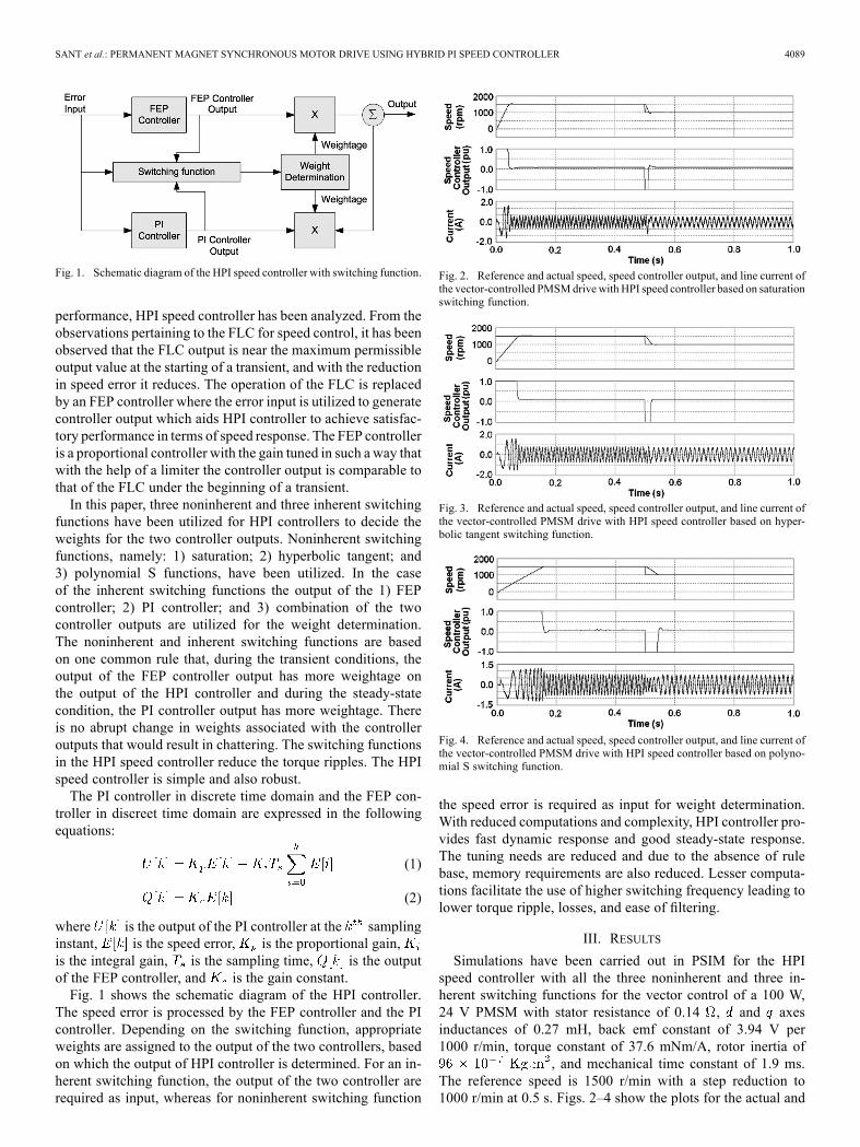
Fig. 1. Schematic diagram of the HPI speed controller with switching function.
performance, HPI speed controller has been analyzed. From theobservations pertaining to the FLC for speed control, it has beenobserved that the FLC output is near the maximum permissibleoutput value at the starting of a transient, and with the reductionin speed error it reduces. The operation of the FLC is replacedby an FEP controller where the error input is utilized to generatecontroller output which aids HPI controller to achieve satisfac-tory performance in terms of speed response. The FEP controlleris a proportional controller with the gain tuned in such a way thatwith the help of a limiter the controller output is comparable tothat of the FLC under the beginning of a transient.In this paper, three noninherent and three inherent switching
functions have been utilized for HPI controllers to decide theweights for the two controller outputs. Noninherent switchingfunctions, namely: 1) saturation; 2) hyperbolic tangent; and3) polynomial S functions, have been utilized. In the caseof the inherent switching functions the output of the 1) FEPcontroller; 2) PI controller; and 3) combination of the twocontroller outputs are utilized for the weight determination.The noninherent and inherent switching functions are basedon one common rule that, during the transient conditions, theoutput of the FEP controller output has more weightage onthe output of the HPI controller and during the steady-statecondition, the PI controller output has more weightage. Thereis no abrupt change in weights associated with the controlleroutputs that would result in chattering. The switching functionsin the HPI speed controller reduce the torque ripples. The HPIspeed controller is simple and also robust.The PI controller in discrete time domain and the FEP con-
troller in discreet time domain are expressed in the followingequations:
(1)
(2)
where is the output of the PI controller at the samplinginstant, is the speed error, is the proportional gain,is the integral gain, is the sampling time, is the outputof the FEP controller, and is the gain constant.Fig. 1 shows the schematic diagram of the HPI controller.
The speed error is processed by the FEP controller and the PIcontroller. Depending on the switching function, appropriateweights are assigned to the output of the two controllers, basedon which the output of HPI controller is determined. For an in-herent switching function, the output of the two controller arerequired as input, whereas for noninherent switching function
Fig. 2. Reference and actual speed, speed controller output, and line current ofthe vector-controlled PMSMdrive with HPI speed controller based on saturationswitching function.
Fig. 3. Reference and actual speed, speed controller output, and line current ofthe vector-controlled PMSM drive with HPI speed controller based on hyper-bolic tangent switching function.
Fig. 4. Reference and actual speed, speed controller output, and line current ofthe vector-controlled PMSM drive with HPI speed controller based on polyno-mial S switching function.
the speed error is required as input for weight determination.With reduced computations and complexity, HPI controller pro-vides fast dynamic response and good steady-state response.The tuning needs are reduced and due to the absence of rulebase, memory requirements are also reduced. Lesser computa-tions facilitate the use of higher switching frequency leading tolower torque ripple, losses, and ease of filtering.
III. RESULTS
Simulations have been carried out in PSIM for the HPIspeed controller with all the three noninherent and three in-herent switching functions for the vector control of a 100 W,24 V PMSM with stator resistance of 0.14 , and axesinductances of 0.27 mH, back emf constant of 3.94 V per1000 r/min, torque constant of 37.6 mNm/A, rotor inertia of
, and mechanical time constant of 1.9 ms.The reference speed is 1500 r/min with a step reduction to1000 r/min at 0.5 s. Figs. 2–4 show the plots for the actual and

4090 IEEE TRANSACTIONS ON MAGNETICS, VOL. 47, NO. 10, OCTOBER 2011
Fig. 5. Reference and actual speed, speed controller output and line currentof the vector-controlled PMSM drive with HPI speed controller with switchingfunction based on the output of FEP controller only.
Fig. 6. Reference and actual speed, speed controller output and line currentof the vector-controlled PMSM drive with HPI speed controller with switchingfunction based on the output of PI controller only.
Fig. 7. Reference and actual speed, speed controller output, and line currentof the vector-controlled PMSM drive with HPI speed controller with switchingfunction based on the average of output of both the FEP and PI controllers.
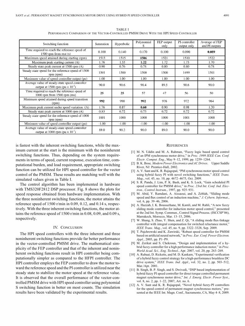
reference speeds, speed controller output, and line current ofthe vector-controlled PMSM with HPI based on noninherentswitching functions. On comparing the drive performance ofthe HPI speed controllers for the vector-controlled PMSM, it isobserved that among noninherent switching functions, the sat-uration-based switching function yields fastest speed responsewith maximum value of the peak starting current among thethree cases. On the other hand, with the polynomial S-basedswitching function, the peak overshoot is the least, 6 r/min, butwith the slowest response and minimum value of peak currentat the starting. The performance with the hyperbolic tangentbased switching function is between the ones obtained with theother two noninherent switching functions. Also with the stepreduction in the reference speed at 0.5 s, the time required toreach the reference speed of 1000 r/min is least in this case.Figs. 5–7 show the plots for the actual and reference speeds,
speed controller output, and line current of the vector-controlledPMSM with HPI based on inherent switching functions. With
Fig. 8. Experimentally measured speed of the vector-controlled PMSM drivewith HPI speed controller with noninherent and inherent switching functions.
inherent switching functions, the speed response is marginallybetter with the combination of the two controllers over the othertwo inherent switching functions, where the output of only onecontroller has been utilized for the derivation of weights. Themaximum current at starting is the minimum in the case of in-herent function with the FEP controller.The details of the simulated drive performance with the HPI
speed controller with the six different switching functions havebeen tabulated in Table I. From the tabulated values, it is ob-served that the performance of the vector-controlled PMSMwith HPI speed controller based on polynomial S switchingfunction is better in general. The reason for the nearly linearspeed response during the transient period is due to the fact thatthe FEP controller output has a prominent weightage during thetransient period. With a high gain, it drives the motor speed to-ward the reference value with the absolute maximum speed con-troller output.A comparison of the drive performance with inherent and
noninherent switching functions results that the speed response
SANT et al.: PERMANENT MAGNET SYNCHRONOUS MOTOR DRIVE USING HYBRID PI SPEED CONTROLLER 4091
TABLE IPERFORMANCE COMPARISON OF THE VECTOR-CONTROLLED PMSM DRIVE WITH THE HPI SPEED CONTROLLER
is fastest with the inherent switching functions, while the max-imum current at the start is the minimum with the noninherentswitching functions. Thus, depending on the system require-ments in terms of speed, current response, execution time, com-putational burden, and load requirement, appropriate switchingfunction can be utilized for HPI speed controller for the vectorcontrol of the PMSM. These results are matching well with thesimulated values given in Table I.The control algorithm has been implemented in hardware
with TMS320F2812 DSP processor. Fig. 8 shows the plots forspeed response obtained from hardware implementation. Withthe three noninherent switching functions, the motor attains thereference speed of 1500 r/min in 0.09, 0.12, and 0.14 s, respec-tively. With the three inherent switching functions, the motor at-tains the reference speed of 1500 r/min in 0.08, 0.09, and 0.09 s,respectively.
IV. CONCLUSION
The HPI speed controllers with the three inherent and threenoninherent switching functions provide far better performancein the vector-controlled PMSM drive. The mathematical sim-plicity of the FEP controller and that of the inherent and nonin-herent switching functions result in HPI controller being com-putationally simpler as compared to the HFPI controller. TheHPI controller employs the FEP controller to draw the motor to-ward the reference speed and the PI controller is utilized near thesteady state to stabilize the motor speed at the reference value.It is observed that the overall performance of the vector-con-trolled PMSMdrive with HPI speed controller using polynomialS switching function in better on most counts. The simulationresults have been validated by the experimental results.
REFERENCES
[1] M. N. Uddin and M. A. Rahman, “Fuzzy logic based speed controlof an IPM synchronous motor drive,” in Proc. 1999 IEEE Can. Conf.Electr. Comput. Eng., May 9–12, 1999, pp. 1259–1264.
[2] B. K. Bose, Modern Power Electronics and ACDrives. Upper SaddleRiver, NJ: Prentice-Hall, 2002.
[3] A. V. Sant and K. R. Rajagopal, “PM synchronous motor speed controlusing hybrid fuzzy PI with novel switching functions,” IEEE Trans.Mag., vol. 45, no. 10, pp. 4672–4675, Oct. 2009.
[4] S. R. Panda, J. Lim, P. K. Bash, and K. S. Lock, “Gain scheduled PIspeed controller for PMSM drive,” in Proc. 23rd Int. Conf. Ind. Elec-tron., Control Instrum., 1997, pp. 925–931.
[5] M. Abid, Y. Ramdani, A. Aissaoui, and A. Zeblah, “Sliding modespeed and flux control of an induction machine,” J. Cybern. Informat.,vol. 6, pp. 39–46, 2006.
[6] A. Hazzab, I. K. Bousserhane, M. Kamli, and M. Rahli, “A new fuzzysliding mode controller for induction motor speed control,” presentedat the 2nd Int. Symp. Commun., Control Signal Process. (ISCCSP’06),Marrakech, Morocco, Mar. 13–15, 2006.
[7] W. Shang, S. Zhao, Y. Shen, and Z. Qi, “A sliding mode flux-linkagecontroller with integral compensation for switched reluctance motor,”IEEE Trans. Mag., vol. 45, no. 9, pp. 3322–3328, Sep. 2009.
[8] T. Pajchrowski and K. Zawirski, “Robust speed controller for PMSMbased on artificial neural network,” in Proc. Eur. Conf. Power Electron.Appl., 2005, pp. P1–P9.
[9] M. Zerikat and S. Chekroun, “Design and implementation of a hy-brid fuzzy controller for a high performance induction motor,” in Proc.World Acad. Sci., Eng. Technol., Apr. 2007, vol. 20, pp. 263–269.
[10] A. Rubaai, D. Ricketts, and M. D. Kankam, “Experimental verificationof a hybrid fuzzy control strategy for a high-performance brushless DCdrive system,” IEEE Trans. Ind. Appl., vol. 32, no. 2, pp. 503–512,Mar./Apr. 2001.
[11] B. Singh, B. P. Singh, and S. Dwivedi, “DSP based implementation ofhybrid fuzzy PI speed controller for direct torque controlled permanentmagnet synchronous motor drive,” Int. J. Emerg. Electr. Power Syst.,vol. 8, no. 2, pp. 1–22, 2007, Art. no. 6.
[12] A. V. Sant and K. R. Rajagopal, “Novel hybrid fuzzy-PI controllersfor the speed control of permanent magnet synchronous motors,” pre-sented at the IEEE Int. Magn. Conf., Sacramento, CA, May 4–8, 2009.