performance studies on coir geotextiles in pavements having soft
TRANSCRIPT
Performance study on Coir Geotextiles in pavements having soft soil subgrade | 1
Performance studies on Coir Geotextiles in Pavements
having Soft Soil Subgrade
Department of Civil Engineering
College of Engineering Trivandrum
Trivandrum- 695016
July 2013
Department of Civil Engineering
College of Engineering Trivandrum
Trivandrum- 695016
January 2015

Performance study on Coir Geotextiles in pavements having soft soil subgrade | 2
CONTENT
SL
No.
Index
Page No
1 Introduction 3
2 Objective of the project 5
3 Literature Review 6
4 Laboratory Experimental Study 17
5 Field Application 32
6 Performance Evaluation 41
7 Conclusion 43
8 Annexure (Photographs) 46
Performance study on Coir Geotextiles in pavements having soft soil subgrade | 3
CHAPTER 1
INTRODUCTION
India has one of the largest road networks in the world, aggregating to about 33 lakh
km at present. However many of the existing roads are becoming structurally inadequate
because of the rapid growth in traffic volume and axle loading. At locations with adequate
subgrade bearing capacity/CBR value, a layer of suitable granular material can improve the
bearing capacity to carry the expected traffic load. But at sites with CBR less than 2%
problems of shear failure and excessive rutting are often encountered. The ground
improvement alternatives such as excavation and replacement of unsuitable material, deep
compaction, chemical stabilization, pre loading and polymeric geosynthetics etc are often
used at such sites. The cost of these processes as well as virgin material involved is usually
high and as such they are yet to be commonly used in developing nations like India. In this
context natural fiber products hold promise for rural road construction over soft clay.
India is the first largest country, producing coir fiber from the husk of coconut fruit.
The coir fiber (50 to 150 mm long and 0.2 to 0.6 mm diameter) till recently were spun into
coir yarn and then woven to obtain woven nettings. The fibers are now a days being needle
punched or adhesive bonded to obtain non woven products or blankets. Geotextiles are
proving to be cost effective alternative to traditional road construction method. Studies have
indicated that the biodegradability of coir can be used to advantage and the coir based
geotextile have the potential of being used for rural road construction over soft clay. In
paved and unpaved road construction, geosynthetic reinforcement has been applied to
improve their overall strength and service life. The stabilization of pavements on soft
ground with geotextiles is primarily attributed to the basic functions of separation of base
course layer from subgrade soil, reinforcement of composite system etc. But these synthetic
products are biodegradable and cause environment problems, whereas natural geotextile
like coir is biodegradable.
Performance study on Coir Geotextiles in pavements having soft soil subgrade | 4
In paved and unpaved road construction, geosynthetic reinforcement has been
applied to improve their overall strength and service life. The stabilization of pavements on
soft ground with geotextiles or geogrid is primarily attributed to basic functions of
separation of base course layer from subgrade soil, reinforcement of composite system etc.
The report presents the results of CBR and plate load test carried in a model test tank
simulating rural roads with coir geotextiles. The results of the test in the laboratory and the
construction of road stretches at 3 locations, with each 100m length are encouraging for use
in developing countries (like India) in rural roads that are yet to be developed to connect as
many as 0.2 million villages as most of these roads happen to be on soft clay. The coir
board has sanctioned the project titled “Performance study on Coir Geotextiles in
pavements having soft soil subgrade” to the department of Civil Engineering, College of
Engineering Trivandrum. The main objective of the project is to construct 100m stretches of
Coir geotextile reinforced road and evaluate the performance. These details of the test
stretches and the results of tests conducted in the laboratory are described in this report.
The details of project are as follows.
Project title: “Performance study on Coir Geotextiles in pavements having soft soil
subgrade”
Name of Investigators:
Principal Investigator of the project : - Dr. Mariamma Joseph,
Professor, Dept. of Civil Engg.,
College of Engg., TVM
Co-Investigators :- Dr. Sheela Evangeline Y.
Associate Professor, Dept. of Civil Engg.,
College of Engg., TVM
Performance study on Coir Geotextiles in pavements having soft soil subgrade | 5
OBJECTIVES OF PROJECT
The main objective of the project is to reduce maintenance cost and increase
pavement longevity of roads in rural roads using Coir Geotextiles. The precise objectives
are the following.
To review the literature on coir geotextile reinforced rural roads.
To study the load settlement behaviour of Coir Geotextile reinforced and unreinforced
subgrade in the laboratory.
To construct 300 m road at 3 location of each 100 m length, rural roads reinforced with
coir geotextiles and study its performances.
Project Sanction date: 15/11/2007
Coir Board order no CCRI/Res/C.Proj/2007
STUDY AREA
Three roads were selected for the study. The 3 roads are selected such that the
subgrade CBR is very low. They are
1. Chirakkad- Kumbakkad Road in Varkala Block [Trivandrum Dist]
2. Mangala Bharathi- SN Kadavu Road in Harippad Block [Alleppy Dist]
3. Kozhimada -Murukkampuzha Road in Kazhakoottom Block [Trivandrum Dist]
All the three roads selected come under PMGSY Scheme.
Performance study on Coir Geotextiles in pavements having soft soil subgrade | 6
CHAPTER 2
LITERATURE REVIEW
2.1 GEOSYNTHETICS
Geosynthetics are Synthesized Polymeric or natural materials used to solve Coir
Engineering problem. The problem of rural roads on soft soil can be solved to some extent
using Geosynthetics. Polymeric materials are polypropylene, polyethylene, nylon, polyester
etc. Natural geosynthetics are produced from natural materials like coir, jute, sisal etc. The
manufacturing process of geotextiles defines two key terms, the machine direction (MD)
and the cross-machine direction (XD). The MD is parallel to the longitudinal (unrolled roll
length) direction, likewise XD corresponds to the shorter length and transverse direction.
A geotextile is similar to a fabric. It is manufactured by interweaving together
numerous yarns in a close-knit pattern. The pattern is tight enough to filter sand/aggregate
particles, thus an apparent opening size (AOS) typically characterizes the openings of a
geotextile
A geosynthetic is affected by its surroundings or Environment. Environmental factors
that contribute to the degradation of geosynthetics include UV radiation (sunlight),
mechanical/physical wear, long duration loads, and temperature. For instance a
polypropylene textile or grid, will creep when exposed to tensile loads. Creep is also
enhanced by an increase in temperature and additionally, UV radiation in sunlight can cause
serious degradation and weakening of polymer bonds.
2.2 HIGHWAY APPLICATIONS
There are many applications of geosynthetics. Even within the highway application
of geosynthetics, further division is necessary for clarity. Geosynthetic highway
applications can be split into two areas, which are unpaved and paved roads. It is important
Performance study on Coir Geotextiles in pavements having soft soil subgrade | 7
to distinguish between the two, since different theories, physical mechanisms, design
methodologies and failure criteria are utilized for each.
2.2.1 Unpaved Road
An unpaved road haul loads across undeveloped terrain. Typically, such grades are
crossed with a minimum amount of preparation that allows for an efficient movement of
relatively few, but heavy, load repetitions. Rutting in the wheel paths is allowed but
typically desired to be four inches or less in depth. Regrading or leveling of the ruts can be
performed but is not typically, considered for an initial design of a layer of select granular
material, which is placed upon the subgrade as a surface course. The purpose of this surface
course is to transfer the surface load to the subgrade while spreading out the load to the
subgrade, which effectively reduces the intensity of pressure on the subgrade (Steward et al.
1977).
A geosynthetic placed properly does improve an unpaved road. The most effective
location of the geosynthetic is below the select granular material and on the subgrade
surface (Das et al. 1998). In this location the geosynthetic provides separation, lateral
restraint of the upper granular course and a tensioned membrane effect when strained
extensively. A geotextile separates a granular course from a fine-grained subgrade, due to
its relatively small apertures or apparent opening size (AOS). However, a geogrid also
provides separation due to its less than 100 percent open area and better lateral restraint of
upper granular particles. Due to interface friction and interlock with many individual ribs, a
geogrid provides superior lateral restraint of the upper granular course, whereas the
geotextile relies exclusively on interface friction for lateral restraint (Steward et al. 1977).
The tensioned membrane effect requires that the geosynthetic be extensively strained (i.e.,
deeply rutted) for this mechanism to contribute a significant benefit.
2.2.2 Paved Road
Performance study on Coir Geotextiles in pavements having soft soil subgrade | 8
The other application is the paved road. This application also encompasses the
unpaved application since during construction of a paved road relatively few repetitions of
trucks heavily loaded with construction materials traverse the partially completed (unpaved)
highway grade. This often leads the road to critical stage. Then, construction is completed
with placement of an asphalt surface course, thus the highway is paved and open to the
public. The opened highway is exposed to many repetitions from loaded truck traffic;
however the intensity of subgrade load is considerably less due to the greater stiffness of the
surface course. Benefits of an underlying geosynthetic during construction are apparent, but
as time and greater numbers of load cycles pass, the benefits are not as clear for the paved
road (Barksdale et al. 1989).
Geogrids and geotextiles are the two types of geosynthetics most widely used in
pavement systems at aggregate subgrade interface to reinforce or stabilize pavements. Field
evidences suggest that both geogrid and geotextile could improve the performance of
pavement sections constructed on weak soil.
Several investigators have reported significant effects of pavement stabilization
using geotextile reinforcement to improve the bearing capacity of subgrade soil.
Steve et al. (2005) conducted a field demonstration to study how the performance of
highway pavements is improved with geotextiles. In his research a field demonstration was
conducted using a 21-m section along a Wisconsin highway (USH 45) near Antigo,
Wisconsin, that incorporated three test sub-sections. Three different geosynthetics including
a woven geotextile and two different types of geogrids had been used for stabilization.
Observations made during and after construction indicate that all sections provided
adequate support for the construction equipment and that no distress seems to be evident in
any part of the highway. Large-scale experiments conducted on working platforms of
crushed rock (breaker run stone or Grade 2 gravel) overlying a simulated soft subgrade. The
tests were intended to simulate conditions during highway construction on soft subgrades
Performance study on Coir Geotextiles in pavements having soft soil subgrade | 9
where the working platform is used to limit total deflections due to repetitive loads applied
by construction traffic. Tests were conducted with and without geosynthetic reinforcement
to evaluate how the required thickness of the working platform is affected by the presence
of reinforcement. Working platforms reinforced by geosynthetics accumulated deformation
at a slower rate than unreinforced working platforms, and in most cases deformation of the
geosynthetic reinforced working platforms nearly ceased after 200 loading cycles. As a
result, total deflections were always smaller (about a factor of two) for reinforced working
platforms relative to unreinforced working platforms.
Hans and Andrew (2001) investigated the reinforcement function of geosynthetics
for a typical Minnesota low volume roadways. From the study it was observed that the
addition of a geosynthetic does provide reinforcement to the roadway as long as the
geosynthetic is stiffer than the subgrade material. The service life of a roadway may also be
increased with the addition of geosynthetic reinforcement. It was also observed that the
deflection response of roadway is governed by the Young’s modulus of the geosynthetic
used. Since the deflections were controlled by the Young’s modulus of the geosynthetic; the
largest modulus geosynthetic produced the largest increase in service life.
Schriver at al. (2002) conducted experimental study on geogrid reinforced
lightweight aggregate beds to determine their subgrade modulus and increase in the bearing
capacity ratio. From study it was observed that the geogrid reinforcement placed at sub
base/aggregate interface effectively increases the service life of paved roads. Geogrid
reinforcement provides a more uniform load distribution and a deduction in maximum
settlement more at the asphalt-aggregate and aggregate-subgrade interface.
Ranadive (2003) investigated the performance of geotextiles reinforcement in soil
other than sand. In this study, model strip footing load tests are conducted on soil with and
without single and multi-layers of geotextile at different depths below the footing. Testing
was carried out on Universal Testing Machine. From the study it was observed that bearing
Performance study on Coir Geotextiles in pavements having soft soil subgrade | 10
capacity improved considerably for reinforced soil over unreinforced soil. It was observed
that for a single layer system, BCR (Bearing Capacity Ratio) for depth of layer below
footing equal to 0.25B is maximum where B is the width of the footing and BCR decreases
as the depth of layer increases and for multilayer system, BCR for a constant d/B ratio and
S/B ratio, (where d is the depth of single reinforcing layer below footing and S is spacing
between subsequent geotextile reinforcing layers when depth of top layer below footing was
kept constant equal to 0.25B). The BCR is maximum for N=4 but the percentage increase in
BCR for N=4 over BCR for N=3 is very low. Thus N=3 is recommended as optimum value.
Gitty and Ajitha (2008) conducted plate load test to study the variation of load
carrying capacity for both reinforced and unreinforced pavements. It was observed that the
bearing capacity improved by providing coir geotextiles as reinforcement. She reported an
increase in bearing capacity by 1.83 times for reinforced pavement compared to
unreinforced pavement.
Venkatappa and Dutta (2005) conducted monotonic and cyclic load test on Kaolinite
with geotextile placed at the interface of the two soils. It was found bearing pressure of the
soil improved by about 33% when reinforced with coir geotextiles.
Indian Roads Congress also suggest in its Rural Road Manual (IRC: SP: 59-2002)
the use of coir geotextile but no design methodology, construction guidelines and product
specifications are mentioned.
COIR GEOTEXTILES
2.3 PERFORMANCE EVALUATION
Performance evaluation of pavement can be classified as functional Performance
and Structural performance.
2.3.1 Functional Performance
Functional Performance can be evaluated by Visual examination, Merlin test and
bump indicator.
Performance study on Coir Geotextiles in pavements having soft soil subgrade | 11
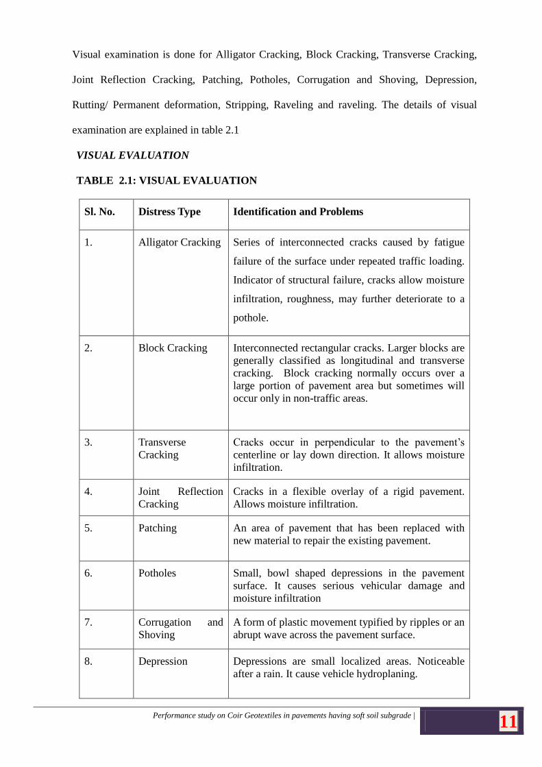
Visual examination is done for Alligator Cracking, Block Cracking, Transverse Cracking,
Joint Reflection Cracking, Patching, Potholes, Corrugation and Shoving, Depression,
Rutting/ Permanent deformation, Stripping, Raveling and raveling. The details of visual
examination are explained in table 2.1
VISUAL EVALUATION
TABLE 2.1: VISUAL EVALUATION
Sl. No. Distress Type Identification and Problems
1. Alligator Cracking Series of interconnected cracks caused by fatigue
failure of the surface under repeated traffic loading.
Indicator of structural failure, cracks allow moisture
infiltration, roughness, may further deteriorate to a
pothole.
2. Block Cracking Interconnected rectangular cracks. Larger blocks are
generally classified as longitudinal and transverse
cracking. Block cracking normally occurs over a
large portion of pavement area but sometimes will
occur only in non-traffic areas.
3. Transverse
Cracking
Cracks occur in perpendicular to the pavement’s
centerline or lay down direction. It allows moisture
infiltration.
4. Joint Reflection
Cracking
Cracks in a flexible overlay of a rigid pavement.
Allows moisture infiltration.
5. Patching An area of pavement that has been replaced with
new material to repair the existing pavement.
6. Potholes Small, bowl shaped depressions in the pavement
surface. It causes serious vehicular damage and
moisture infiltration
7. Corrugation and
Shoving
A form of plastic movement typified by ripples or an
abrupt wave across the pavement surface.
8. Depression Depressions are small localized areas. Noticeable
after a rain. It cause vehicle hydroplaning.
Performance study on Coir Geotextiles in pavements having soft soil subgrade | 12
9. Rutting/
Permanent
deformation
Surface depression along the wheel path. Ruts filled
with water can cause vehicle hydroplaning, can be
hazardous because ruts tend to pull a vehicle
towards the rut path as it is steered across the rut.
10. Stripping The loss of bond between aggregates & asphalt
binder. It causes decrease in structural support,
rutting, shoving/corrugations raveling or cracking.
11. Raveling The progressive disintegration of an layer from the
surface downward as a result of the dislodgement of
aggregate particles. It causes loose debris on the
pavement, roughness, water collecting in the raveled
locations resulting in vehicle hydroplaning, loss of
skid resistance.
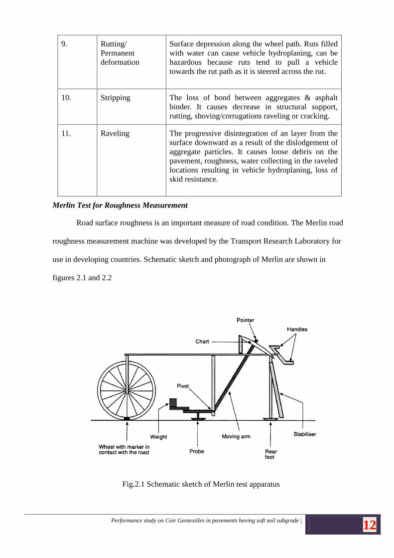
Merlin Test for Roughness Measurement
Road surface roughness is an important measure of road condition. The Merlin road
roughness measurement machine was developed by the Transport Research Laboratory for
use in developing countries. Schematic sketch and photograph of Merlin are shown in
figures 2.1 and 2.2
Fig.2.1 Schematic sketch of Merlin test apparatus
Performance study on Coir Geotextiles in pavements having soft soil subgrade | 13
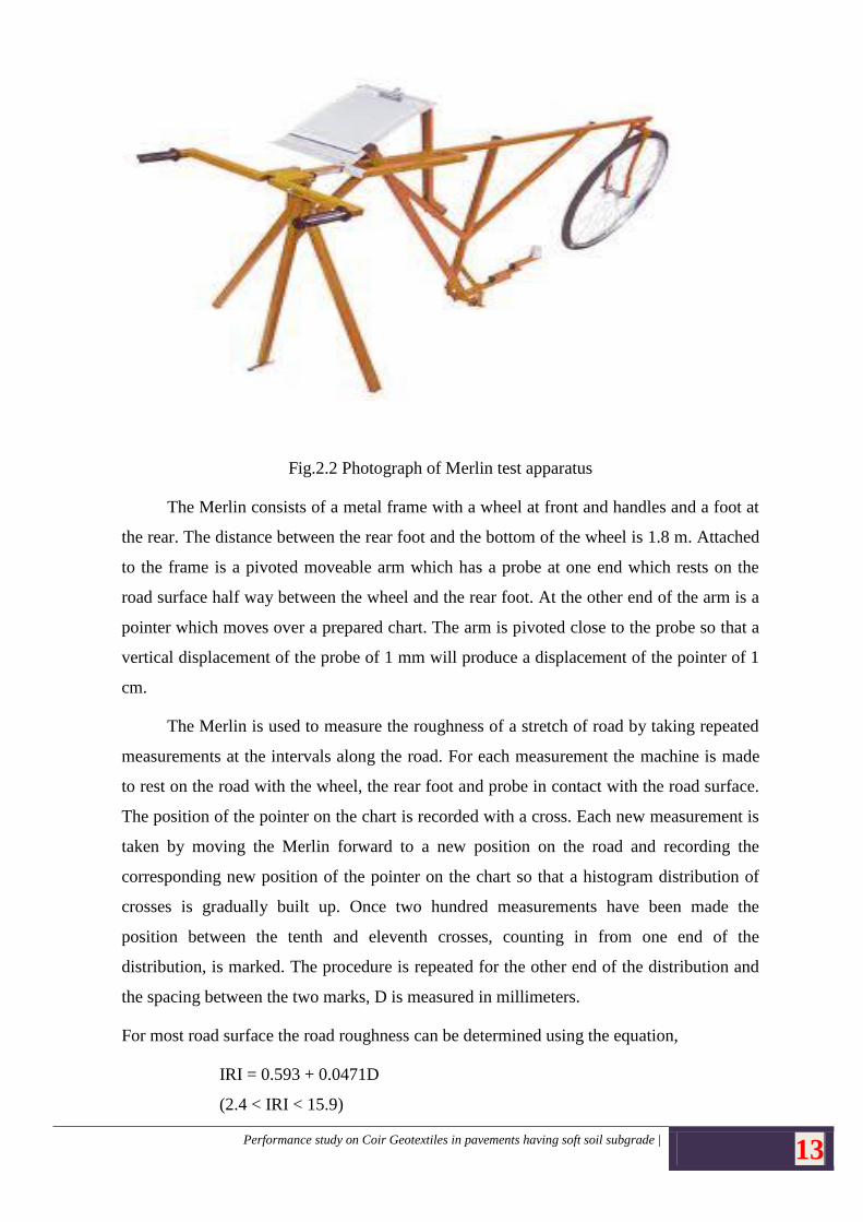
Fig.2.2 Photograph of Merlin test apparatus
The Merlin consists of a metal frame with a wheel at front and handles and a foot at
the rear. The distance between the rear foot and the bottom of the wheel is 1.8 m. Attached
to the frame is a pivoted moveable arm which has a probe at one end which rests on the
road surface half way between the wheel and the rear foot. At the other end of the arm is a
pointer which moves over a prepared chart. The arm is pivoted close to the probe so that a
vertical displacement of the probe of 1 mm will produce a displacement of the pointer of 1
cm.
The Merlin is used to measure the roughness of a stretch of road by taking repeated
measurements at the intervals along the road. For each measurement the machine is made
to rest on the road with the wheel, the rear foot and probe in contact with the road surface.
The position of the pointer on the chart is recorded with a cross. Each new measurement is
taken by moving the Merlin forward to a new position on the road and recording the
corresponding new position of the pointer on the chart so that a histogram distribution of
crosses is gradually built up. Once two hundred measurements have been made the
position between the tenth and eleventh crosses, counting in from one end of the
distribution, is marked. The procedure is repeated for the other end of the distribution and
the spacing between the two marks, D is measured in millimeters.
For most road surface the road roughness can be determined using the equation,
IRI = 0.593 + 0.0471D
(2.4 < IRI < 15.9)
Performance study on Coir Geotextiles in pavements having soft soil subgrade | 14
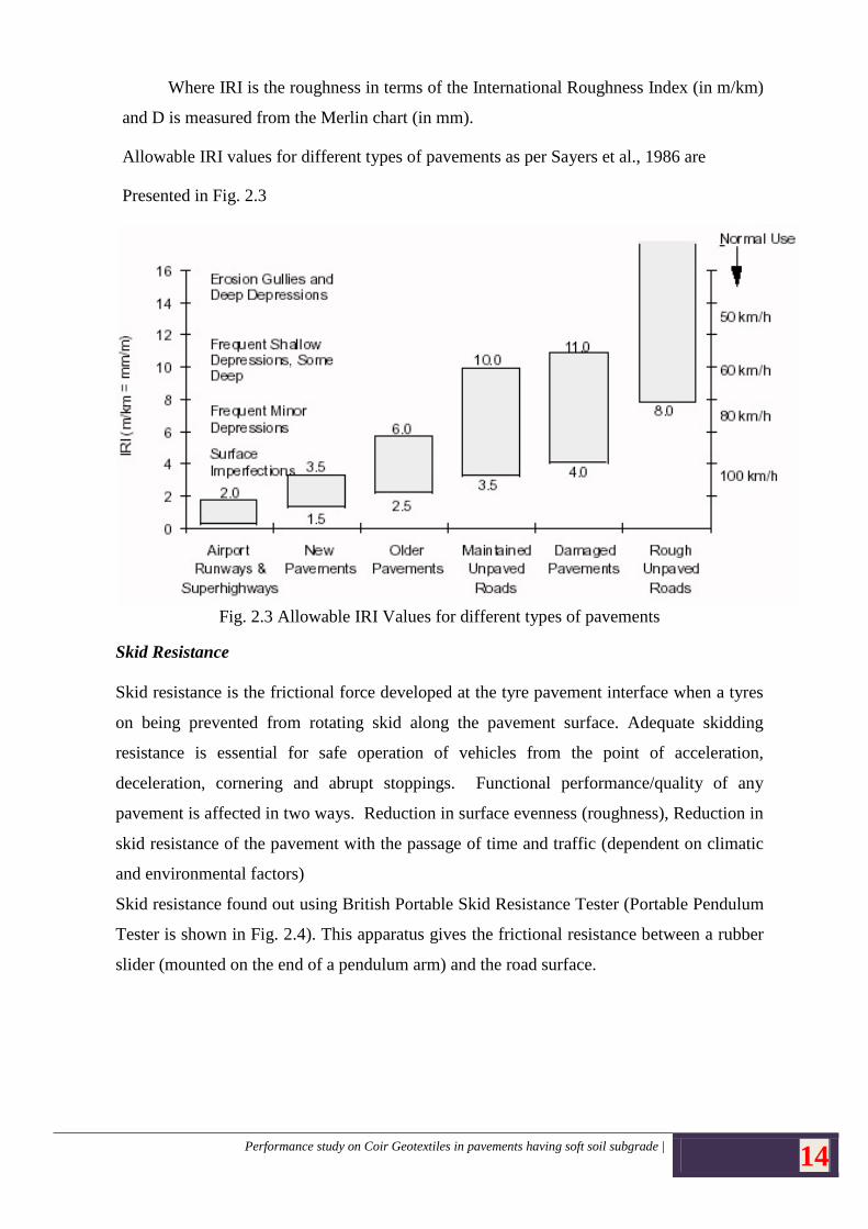
Where IRI is the roughness in terms of the International Roughness Index (in m/km)
and D is measured from the Merlin chart (in mm).
Allowable IRI values for different types of pavements as per Sayers et al., 1986 are
Presented in Fig. 2.3
Fig. 2.3 Allowable IRI Values for different types of pavements
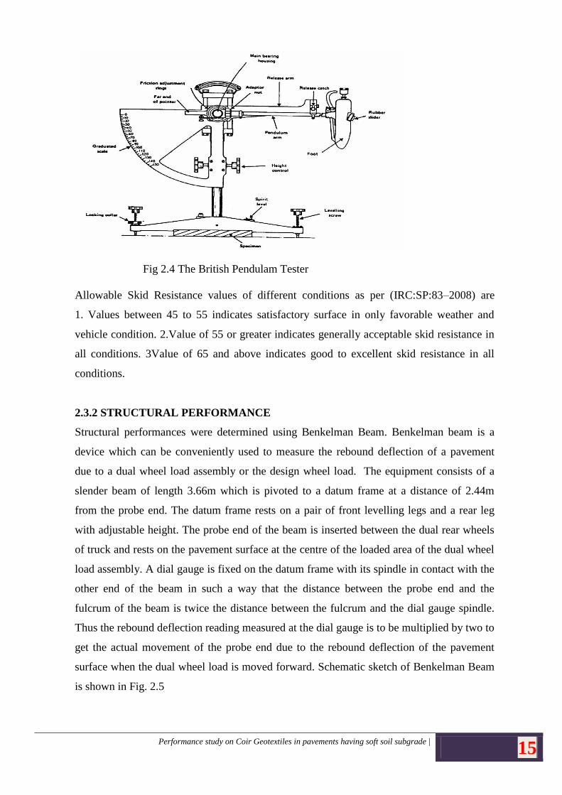
Skid Resistance
Skid resistance is the frictional force developed at the tyre pavement interface when a tyres
on being prevented from rotating skid along the pavement surface. Adequate skidding
resistance is essential for safe operation of vehicles from the point of acceleration,
deceleration, cornering and abrupt stoppings. Functional performance/quality of any
pavement is affected in two ways. Reduction in surface evenness (roughness), Reduction in
skid resistance of the pavement with the passage of time and traffic (dependent on climatic
and environmental factors)
Skid resistance found out using British Portable Skid Resistance Tester (Portable Pendulum
Tester is shown in Fig. 2.4). This apparatus gives the frictional resistance between a rubber
slider (mounted on the end of a pendulum arm) and the road surface.
Performance study on Coir Geotextiles in pavements having soft soil subgrade | 15
Fig 2.4 The British Pendulam Tester
Allowable Skid Resistance values of different conditions as per (IRC:SP:83–2008) are
1. Values between 45 to 55 indicates satisfactory surface in only favorable weather and
vehicle condition. 2.Value of 55 or greater indicates generally acceptable skid resistance in
all conditions. 3Value of 65 and above indicates good to excellent skid resistance in all
conditions.
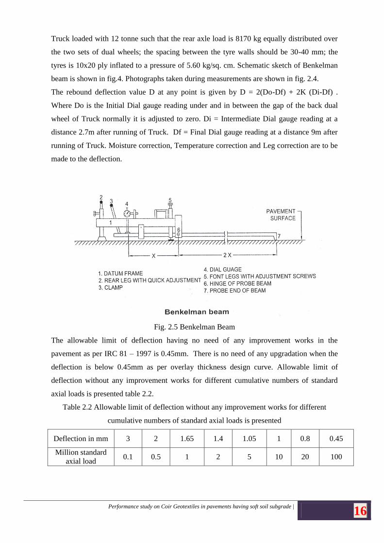
2.3.2 STRUCTURAL PERFORMANCE
Structural performances were determined using Benkelman Beam. Benkelman beam is a
device which can be conveniently used to measure the rebound deflection of a pavement
due to a dual wheel load assembly or the design wheel load. The equipment consists of a
slender beam of length 3.66m which is pivoted to a datum frame at a distance of 2.44m
from the probe end. The datum frame rests on a pair of front levelling legs and a rear leg
with adjustable height. The probe end of the beam is inserted between the dual rear wheels
of truck and rests on the pavement surface at the centre of the loaded area of the dual wheel
load assembly. A dial gauge is fixed on the datum frame with its spindle in contact with the
other end of the beam in such a way that the distance between the probe end and the
fulcrum of the beam is twice the distance between the fulcrum and the dial gauge spindle.
Thus the rebound deflection reading measured at the dial gauge is to be multiplied by two to
get the actual movement of the probe end due to the rebound deflection of the pavement
surface when the dual wheel load is moved forward. Schematic sketch of Benkelman Beam
is shown in Fig. 2.5
Performance study on Coir Geotextiles in pavements having soft soil subgrade | 16
Truck loaded with 12 tonne such that the rear axle load is 8170 kg equally distributed over
the two sets of dual wheels; the spacing between the tyre walls should be 30-40 mm; the
tyres is 10x20 ply inflated to a pressure of 5.60 kg/sq. cm. Schematic sketch of Benkelman
beam is shown in fig.4. Photographs taken during measurements are shown in fig. 2.4.
The rebound deflection value D at any point is given by D = 2(Do-Df) + 2K (Di-Df) .
Where Do is the Initial Dial gauge reading under and in between the gap of the back dual
wheel of Truck normally it is adjusted to zero. Di = Intermediate Dial gauge reading at a
distance 2.7m after running of Truck. Df = Final Dial gauge reading at a distance 9m after
running of Truck. Moisture correction, Temperature correction and Leg correction are to be
made to the deflection.
Fig. 2.5 Benkelman Beam
The allowable limit of deflection having no need of any improvement works in the
pavement as per IRC 81 – 1997 is 0.45mm. There is no need of any upgradation when the
deflection is below 0.45mm as per overlay thickness design curve. Allowable limit of
deflection without any improvement works for different cumulative numbers of standard
axial loads is presented table 2.2.
Table 2.2 Allowable limit of deflection without any improvement works for different
cumulative numbers of standard axial loads is presented
Deflection in mm 3 2 1.65 1.4 1.05 1 0.8 0.45
Million standard
axial load 0.1 0.5 1 2 5 10 20 100
Performance study on Coir Geotextiles in pavements having soft soil subgrade | 17
CHAPTER 3
LABORATORY EXPERIMENTAL STUDY
3.1 MATERIALS USED
The materials used for the study are soil and geotextile. The soils were collected
from the three different locations selected for field study. They are Haripad, Varkala and
Kozhinada. Local as well as fill soil were collected and tested in the laboratory. The
geotextiles used for the study were H2M6, H2M8 and non woven geotextiles.
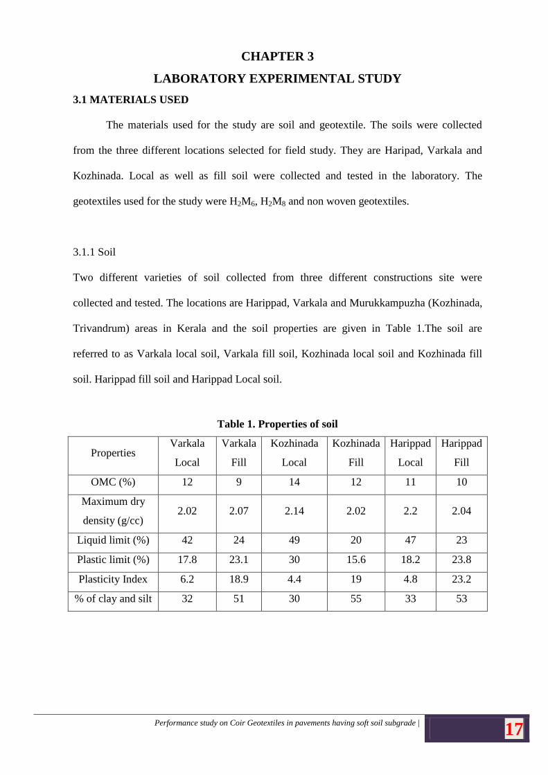
3.1.1 Soil
Two different varieties of soil collected from three different constructions site were
collected and tested. The locations are Harippad, Varkala and Murukkampuzha (Kozhinada,
Trivandrum) areas in Kerala and the soil properties are given in Table 1.The soil are
referred to as Varkala local soil, Varkala fill soil, Kozhinada local soil and Kozhinada fill
soil. Harippad fill soil and Harippad Local soil.
Table 1. Properties of soil
Properties Varkala
Local
Varkala
Fill
Kozhinada
Local
Kozhinada
Fill
Harippad
Local
Harippad
Fill
OMC (%) 12 9 14 12 11 10
Maximum dry
density (g/cc) 2.02 2.07 2.14 2.02 2.2 2.04
Liquid limit (%) 42 24 49 20 47 23
Plastic limit (%) 17.8 23.1 30 15.6 18.2 23.8
Plasticity Index 6.2 18.9 4.4 19 4.8 23.2
% of clay and silt 32 51 30 55 33 53
Performance study on Coir Geotextiles in pavements having soft soil subgrade | 18
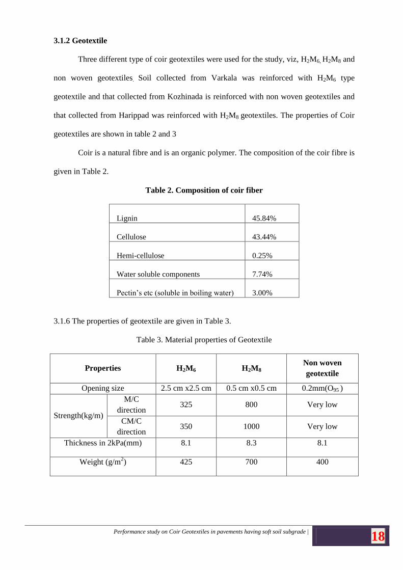
3.1.2 Geotextile
Three different type of coir geotextiles were used for the study, viz, H2M6, H2M8 and
non woven geotextiles. Soil collected from Varkala was reinforced with H2M6 type
geotextile and that collected from Kozhinada is reinforced with non woven geotextiles and
that collected from Harippad was reinforced with H2M8 geotextiles. The properties of Coir
geotextiles are shown in table 2 and 3
Coir is a natural fibre and is an organic polymer. The composition of the coir fibre is
given in Table 2.
Table 2. Composition of coir fiber
Lignin
45.84%
Cellulose
43.44%
Hemi-cellulose
0.25%
Water soluble components
7.74%
Pectin’s etc (soluble in boiling water)
3.00%
3.1.6 The properties of geotextile are given in Table 3.
Table 3. Material properties of Geotextile
Properties H2M6 H2M8 Non woven
geotextile
Opening size 2.5 cm x2.5 cm 0.5 cm x0.5 cm 0.2mm(O95 )
Strength(kg/m)
M/C
direction 325 800 Very low
CM/C
direction 350 1000 Very low
Thickness in 2kPa(mm) 8.1 8.3 8.1
Weight (g/m2) 425 700 400
Performance study on Coir Geotextiles in pavements having soft soil subgrade | 19
3.2 LABORATORY STUDY
a) CBR Tests
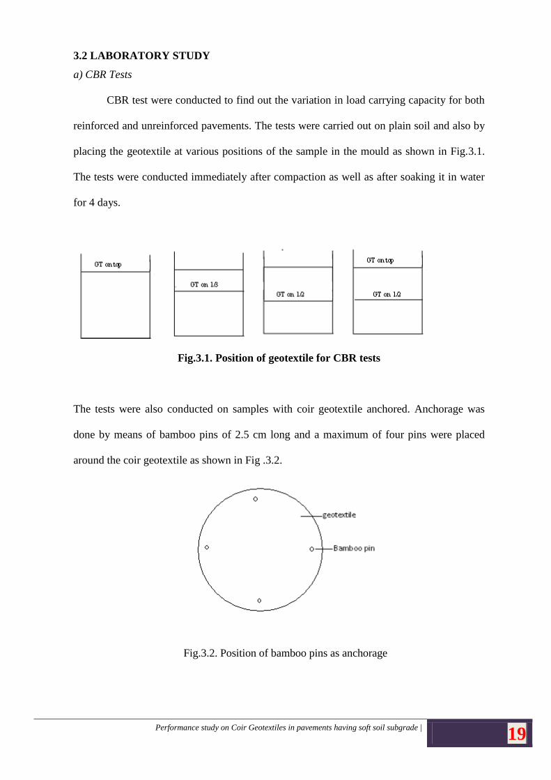
CBR test were conducted to find out the variation in load carrying capacity for both
reinforced and unreinforced pavements. The tests were carried out on plain soil and also by
placing the geotextile at various positions of the sample in the mould as shown in Fig.3.1.
The tests were conducted immediately after compaction as well as after soaking it in water
for 4 days.
Fig.3.1. Position of geotextile for CBR tests
The tests were also conducted on samples with coir geotextile anchored. Anchorage was
done by means of bamboo pins of 2.5 cm long and a maximum of four pins were placed
around the coir geotextile as shown in Fig .3.2.
Fig.3.2. Position of bamboo pins as anchorage
Performance study on Coir Geotextiles in pavements having soft soil subgrade | 20
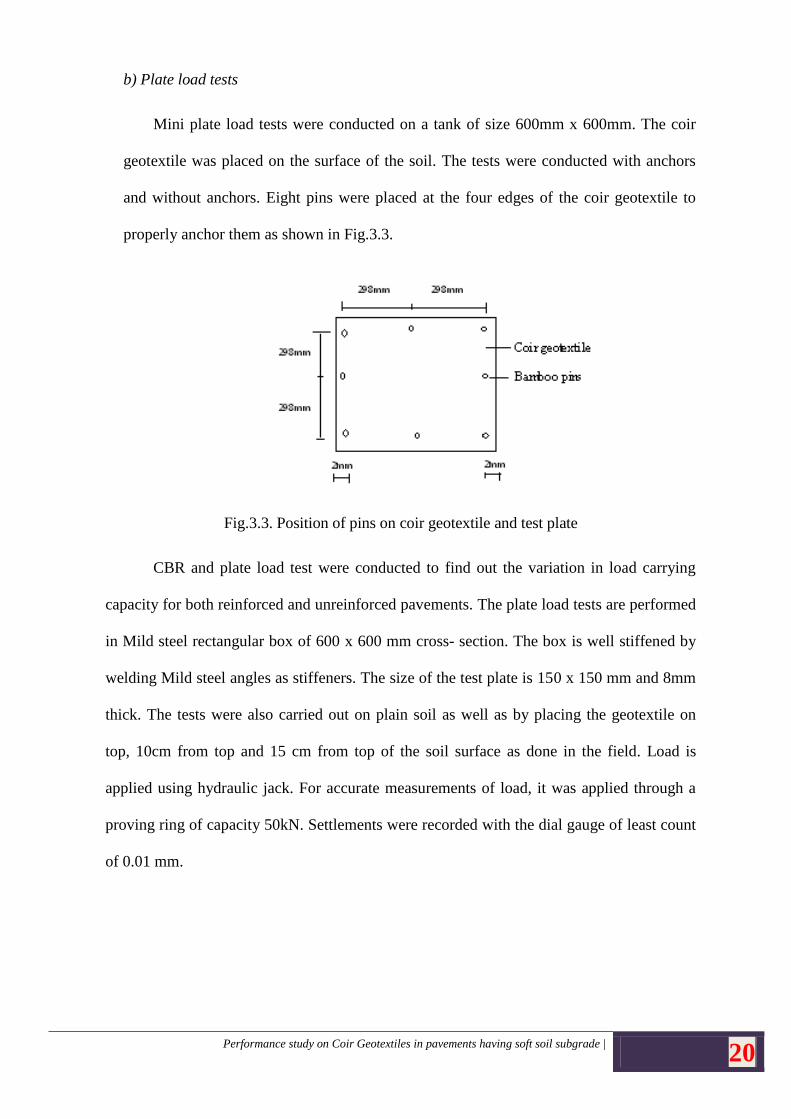
b) Plate load tests
Mini plate load tests were conducted on a tank of size 600mm x 600mm. The coir
geotextile was placed on the surface of the soil. The tests were conducted with anchors
and without anchors. Eight pins were placed at the four edges of the coir geotextile to
properly anchor them as shown in Fig.3.3.
Fig.3.3. Position of pins on coir geotextile and test plate
CBR and plate load test were conducted to find out the variation in load carrying
capacity for both reinforced and unreinforced pavements. The plate load tests are performed
in Mild steel rectangular box of 600 x 600 mm cross- section. The box is well stiffened by
welding Mild steel angles as stiffeners. The size of the test plate is 150 x 150 mm and 8mm
thick. The tests were also carried out on plain soil as well as by placing the geotextile on
top, 10cm from top and 15 cm from top of the soil surface as done in the field. Load is
applied using hydraulic jack. For accurate measurements of load, it was applied through a
proving ring of capacity 50kN. Settlements were recorded with the dial gauge of least count
of 0.01 mm.
Performance study on Coir Geotextiles in pavements having soft soil subgrade | 21
3.3 RESULTS AND DISCUSSION
Results of tests done in the laboratory are discussed below.
3.3.1 VARKALA LOCAL SOIL
3.3.1 CBR test Results
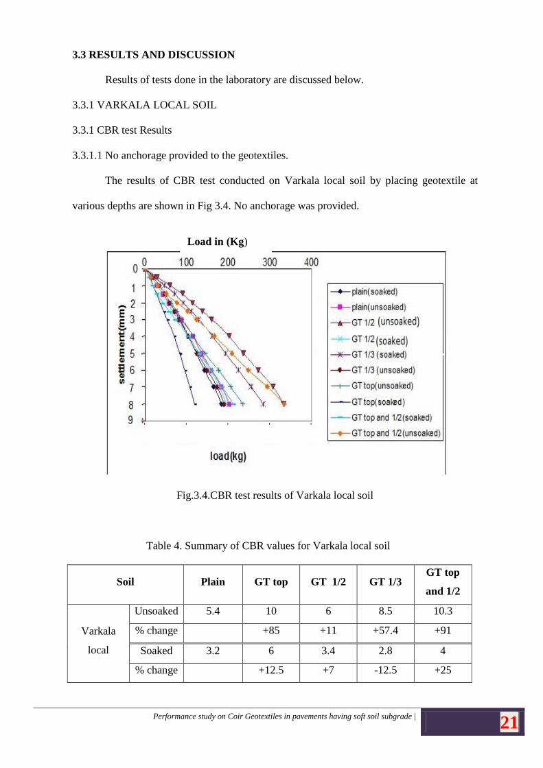
3.3.1.1 No anchorage provided to the geotextiles.
The results of CBR test conducted on Varkala local soil by placing geotextile at
various depths are shown in Fig 3.4. No anchorage was provided.
Fig.3.4.CBR test results of Varkala local soil
Table 4. Summary of CBR values for Varkala local soil
Soil Plain GT top GT 1/2 GT 1/3 GT top
and 1/2
Varkala
local
Unsoaked 5.4 10 6 8.5 10.3
% change +85 +11 +57.4 +91
Soaked 3.2 6 3.4 2.8 4
% change +12.5 +7 -12.5 +25
Load in (Kg)
Performance study on Coir Geotextiles in pavements having soft soil subgrade | 22
From Table 4 it can be observed that the CBR values for soil reinforced with
geotextiles shows a lower CBR value than that obtained for reinforced case in case of
soaked soil. This decrease may be attributed to the slippage of the geotextile that takes place
between the soil layers. In the field layer slippage doesn’t happen. Hence anchors were
provided and the CBR test was repeated.
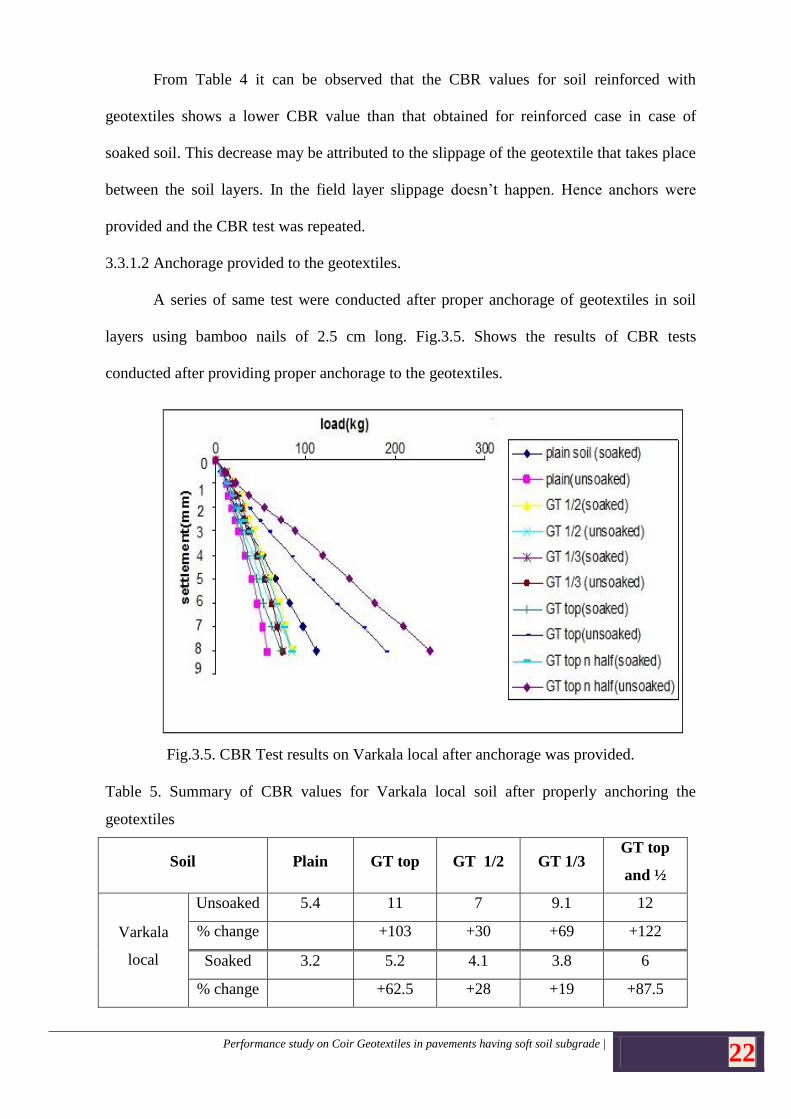
3.3.1.2 Anchorage provided to the geotextiles.
A series of same test were conducted after proper anchorage of geotextiles in soil
layers using bamboo nails of 2.5 cm long. Fig.3.5. Shows the results of CBR tests
conducted after providing proper anchorage to the geotextiles.
Fig.3.5. CBR Test results on Varkala local after anchorage was provided.
Table 5. Summary of CBR values for Varkala local soil after properly anchoring the
geotextiles
Soil Plain GT top GT 1/2 GT 1/3 GT top
and ½
Varkala
local
Unsoaked 5.4 11 7 9.1 12
% change +103 +30 +69 +122
Soaked 3.2 5.2 4.1 3.8 6
% change +62.5 +28 +19 +87.5
Performance study on Coir Geotextiles in pavements having soft soil subgrade | 23
From Table 5 it was observed that a percentage increase of 122% was seen when
two layers of geotextiles was placed at top and half the depth from top of the subgrade.
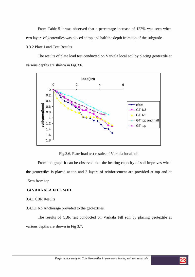
3.3.2 Plate Load Test Results
The results of plate load test conducted on Varkala local soil by placing geotextile at
various depths are shown in Fig.3.6.
Fig.3.6. Plate load test results of Varkala local soil
From the graph it can be observed that the bearing capacity of soil improves when
the geotextiles is placed at top and 2 layers of reinforcement are provided at top and at
15cm from top
3.4 VARKALA FILL SOIL
3.4.1 CBR Results
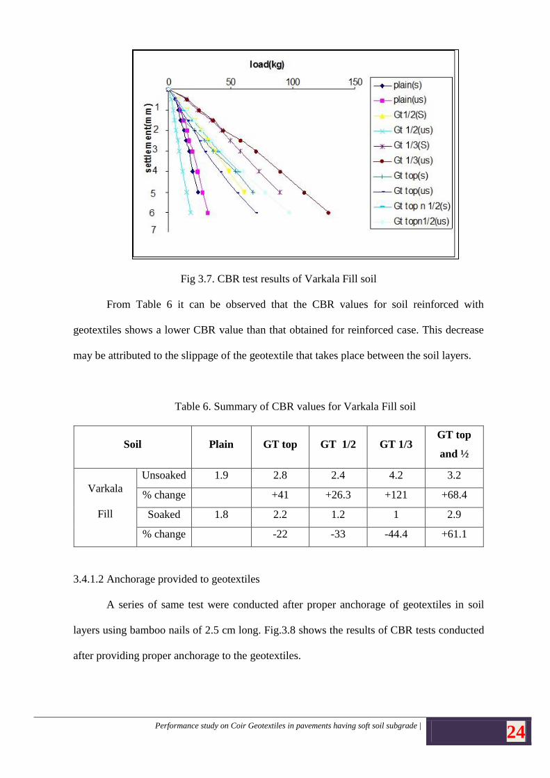
3.4.1.1 No Anchorage provided to the geotextiles.
The results of CBR test conducted on Varkala Fill soil by placing geotextile at
various depths are shown in Fig 3.7.
0
0.2
0.4
0.6
0.8
1
1.2
1.4
1.6
1.8
0 2 4 6
load(kN)
sett
lem
en
t(m
m) plain
GT 1/3
GT 1/2
GT top and half
GT top
Performance study on Coir Geotextiles in pavements having soft soil subgrade | 24
Fig 3.7. CBR test results of Varkala Fill soil
From Table 6 it can be observed that the CBR values for soil reinforced with
geotextiles shows a lower CBR value than that obtained for reinforced case. This decrease
may be attributed to the slippage of the geotextile that takes place between the soil layers.
Table 6. Summary of CBR values for Varkala Fill soil
Soil Plain GT top GT 1/2 GT 1/3 GT top
and ½
Varkala
Fill
Unsoaked 1.9 2.8 2.4 4.2 3.2
% change +41 +26.3 +121 +68.4
Soaked 1.8 2.2 1.2 1 2.9
% change -22 -33 -44.4 +61.1
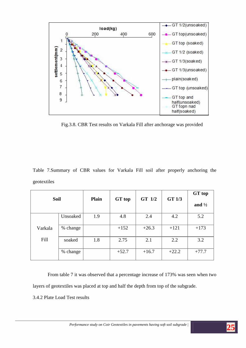
3.4.1.2 Anchorage provided to geotextiles
A series of same test were conducted after proper anchorage of geotextiles in soil
layers using bamboo nails of 2.5 cm long. Fig.3.8 shows the results of CBR tests conducted
after providing proper anchorage to the geotextiles.
Performance study on Coir Geotextiles in pavements having soft soil subgrade | 25
Fig.3.8. CBR Test results on Varkala Fill after anchorage was provided
Table 7.Summary of CBR values for Varkala Fill soil after properly anchoring the
geotextiles
Soil Plain GT top GT 1/2 GT 1/3
GT top
and ½
Varkala
Fill
Unsoaked 1.9 4.8 2.4 4.2 5.2
% change +152 +26.3 +121 +173
soaked 1.8 2.75 2.1 2.2 3.2
% change +52.7 +16.7 +22.2 +77.7
From table 7 it was observed that a percentage increase of 173% was seen when two
layers of geotextiles was placed at top and half the depth from top of the subgrade.
3.4.2 Plate Load Test results
Performance study on Coir Geotextiles in pavements having soft soil subgrade | 26
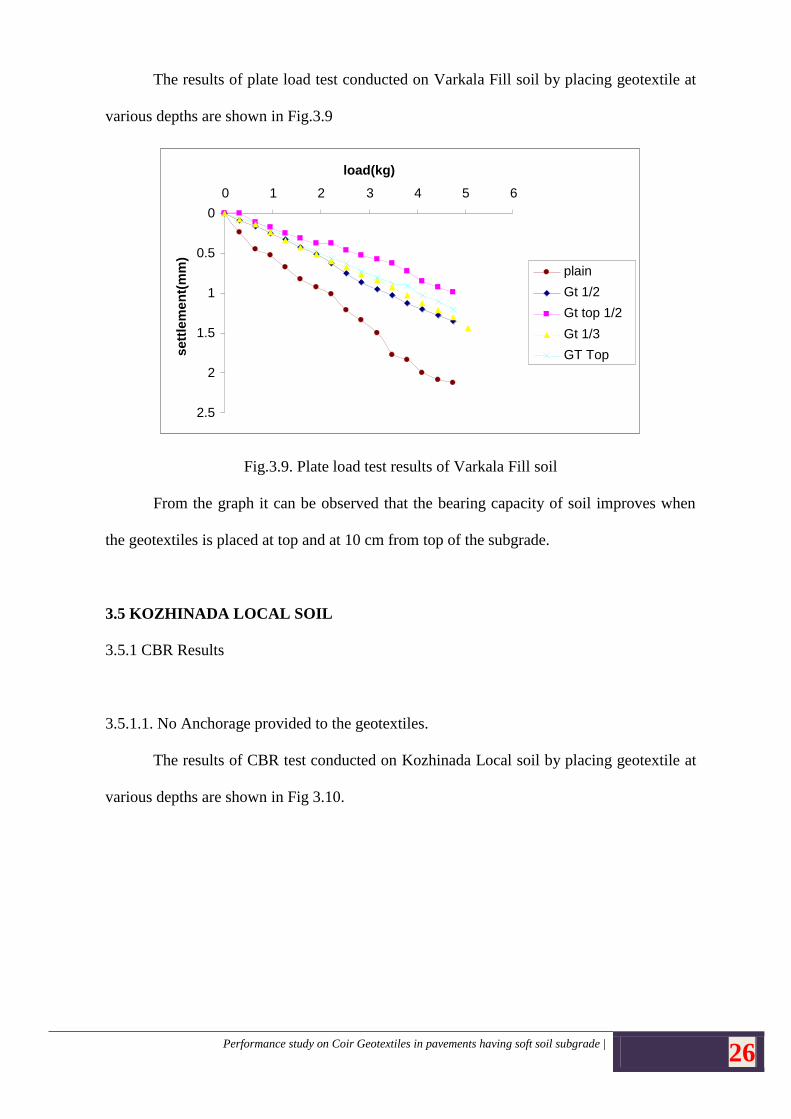
The results of plate load test conducted on Varkala Fill soil by placing geotextile at
various depths are shown in Fig.3.9
Fig.3.9. Plate load test results of Varkala Fill soil
From the graph it can be observed that the bearing capacity of soil improves when
the geotextiles is placed at top and at 10 cm from top of the subgrade.
3.5 KOZHINADA LOCAL SOIL
3.5.1 CBR Results
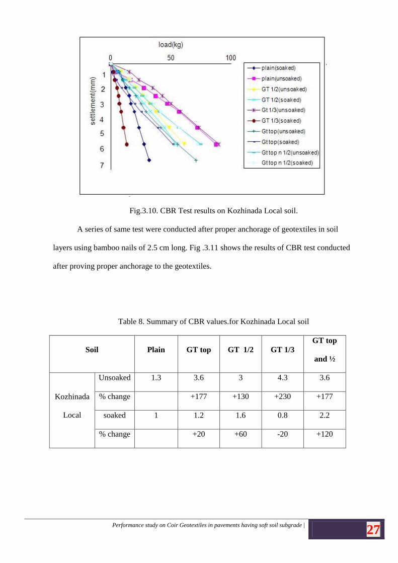
3.5.1.1. No Anchorage provided to the geotextiles.
The results of CBR test conducted on Kozhinada Local soil by placing geotextile at
various depths are shown in Fig 3.10.
0
0.5
1
1.5
2
2.5
0 1 2 3 4 5 6
load(kg)
plain
Gt 1/2
Gt top 1/2
Gt 1/3
GT Top sett
lem
en
t(m
m)
Performance study on Coir Geotextiles in pavements having soft soil subgrade | 27
Fig.3.10. CBR Test results on Kozhinada Local soil.
A series of same test were conducted after proper anchorage of geotextiles in soil
layers using bamboo nails of 2.5 cm long. Fig .3.11 shows the results of CBR test conducted
after proving proper anchorage to the geotextiles.
Table 8. Summary of CBR values.for Kozhinada Local soil
Soil Plain GT top GT 1/2 GT 1/3
GT top
and ½
Kozhinada
Local
Unsoaked 1.3 3.6 3 4.3 3.6
% change +177 +130 +230 +177
soaked 1 1.2 1.6 0.8 2.2
% change +20 +60 -20 +120
Performance study on Coir Geotextiles in pavements having soft soil subgrade | 28
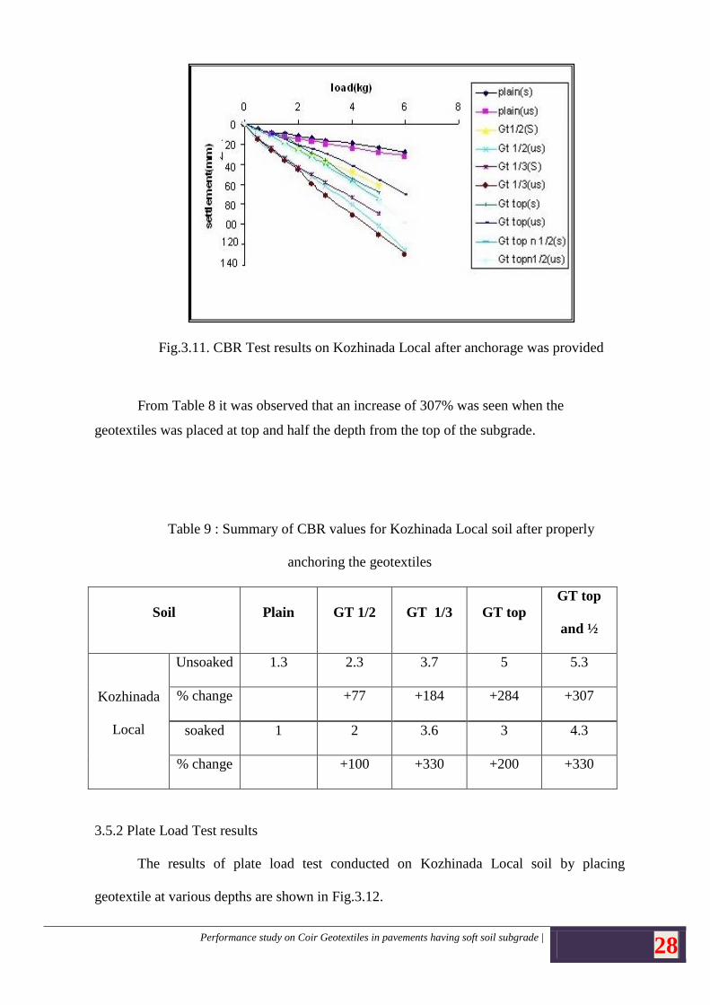
Fig.3.11. CBR Test results on Kozhinada Local after anchorage was provided
From Table 8 it was observed that an increase of 307% was seen when the
geotextiles was placed at top and half the depth from the top of the subgrade.
Table 9 : Summary of CBR values for Kozhinada Local soil after properly
anchoring the geotextiles
Soil Plain GT 1/2 GT 1/3 GT top
GT top
and ½
Kozhinada
Local
Unsoaked 1.3 2.3 3.7 5 5.3
% change +77 +184 +284 +307
soaked 1 2 3.6 3 4.3
% change +100 +330 +200 +330
3.5.2 Plate Load Test results
The results of plate load test conducted on Kozhinada Local soil by placing
geotextile at various depths are shown in Fig.3.12.
Performance study on Coir Geotextiles in pavements having soft soil subgrade | 29
Fig.3.12. Plate load test results of Kozhinada Local soil.
From the graph it can be observed that the bearing capacity of soil improves when
the geotextiles was placed at top and half the depth from the top of the subgrade.
3.6 KOZHINADA FILL SOIL
3.6.1 CBR Results
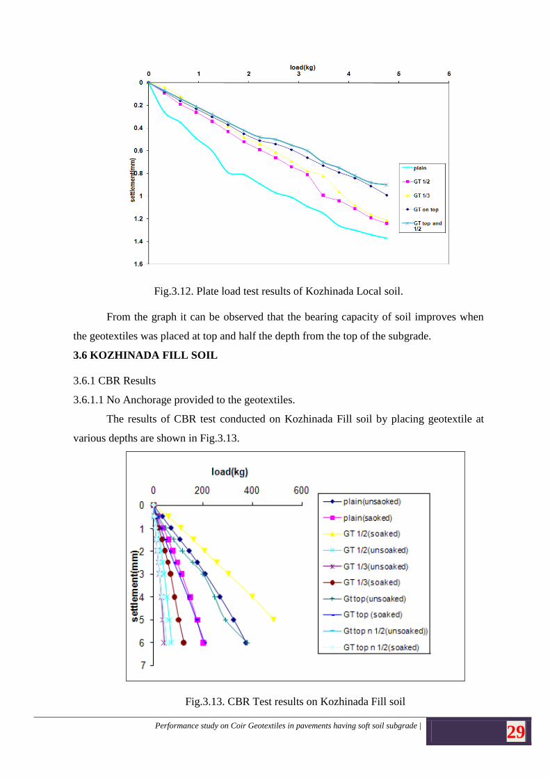
3.6.1.1 No Anchorage provided to the geotextiles.
The results of CBR test conducted on Kozhinada Fill soil by placing geotextile at
various depths are shown in Fig.3.13.
Fig.3.13. CBR Test results on Kozhinada Fill soil
Performance study on Coir Geotextiles in pavements having soft soil subgrade | 30
From Table 10 it can be observed that the CBR values for soil reinforced with
geotextiles shows a lower CBR value than that obtained for reinforced case. This decrease
may be attributed to the slippage of the geotextile that takes place between the soil layers.
Table 10. Summary of CBR values for KF soil
Soil Plain GT top GT ½ GT 1/3
GT top
and ½
Kozhinada
Fill
Unsoaked 15.8 14.8 18 12.8 14.72
% change -6.3 +12.2 -19 -6.9
soaked 7 6.2 8.3 9.5 5.4
% change -11.4 +18.5 +36 -23
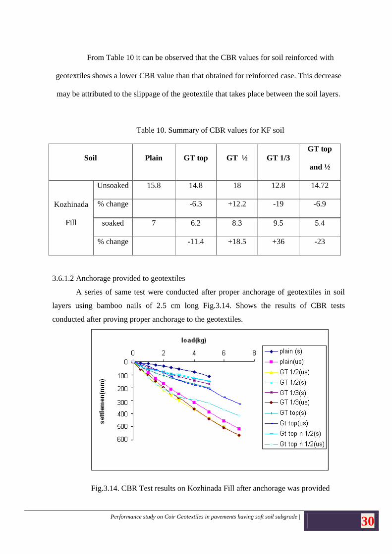
3.6.1.2 Anchorage provided to geotextiles
A series of same test were conducted after proper anchorage of geotextiles in soil
layers using bamboo nails of 2.5 cm long Fig.3.14. Shows the results of CBR tests
conducted after proving proper anchorage to the geotextiles.
Fig.3.14. CBR Test results on Kozhinada Fill after anchorage was provided
Performance study on Coir Geotextiles in pavements having soft soil subgrade | 31
Table 11. Summary of CBR values for Kozhinada Fill soil after properly anchoring
the geotextiles
Soil Plain GT top GT 1/2 GT 1/3 GT top
and ½
Kozhinada
Fill
Unsoaked 15.8 21.5 21.2 21.3 22
% change +36 +34 +34 +39
Soaked 7 10 8.3 9.5 12
% change +43 +18.5 +35.7 +71.4
From Table 11 it was seen that an increase of around 35% was seen when the soil was
reinforced with geotextiles and an increase of 39% was seen when two layers of geotextle
was placed at top and half the depth from top of the subgrade.
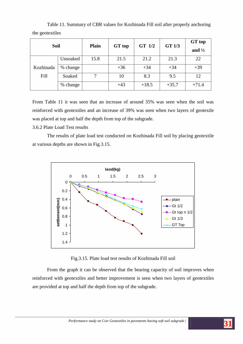
3.6.2 Plate Load Test results
The results of plate load test conducted on Kozhinada Fill soil by placing geotextile
at various depths are shown in Fig.3.15.
Fig.3.15. Plate load test results of Kozhinada Fill soil
From the graph it can be observed that the bearing capacity of soil improves when
reinforced with geotextiles and better improvement is seen when two layers of geotextiles
are provided at top and half the depth from top of the subgrade.
0
0.2
0.4
0.6
0.8
1
1.2
1.4
0 0.5 1 1.5 2 2.5 3
laod(kg)
sett
lem
en
t(m
m) plain
Gt 1/2
Gt top n 1/2
Gt 1/3
GT Top
Performance study on Coir Geotextiles in pavements having soft soil subgrade | 32
CHAPTER 4
FIELD APPLICATIONS
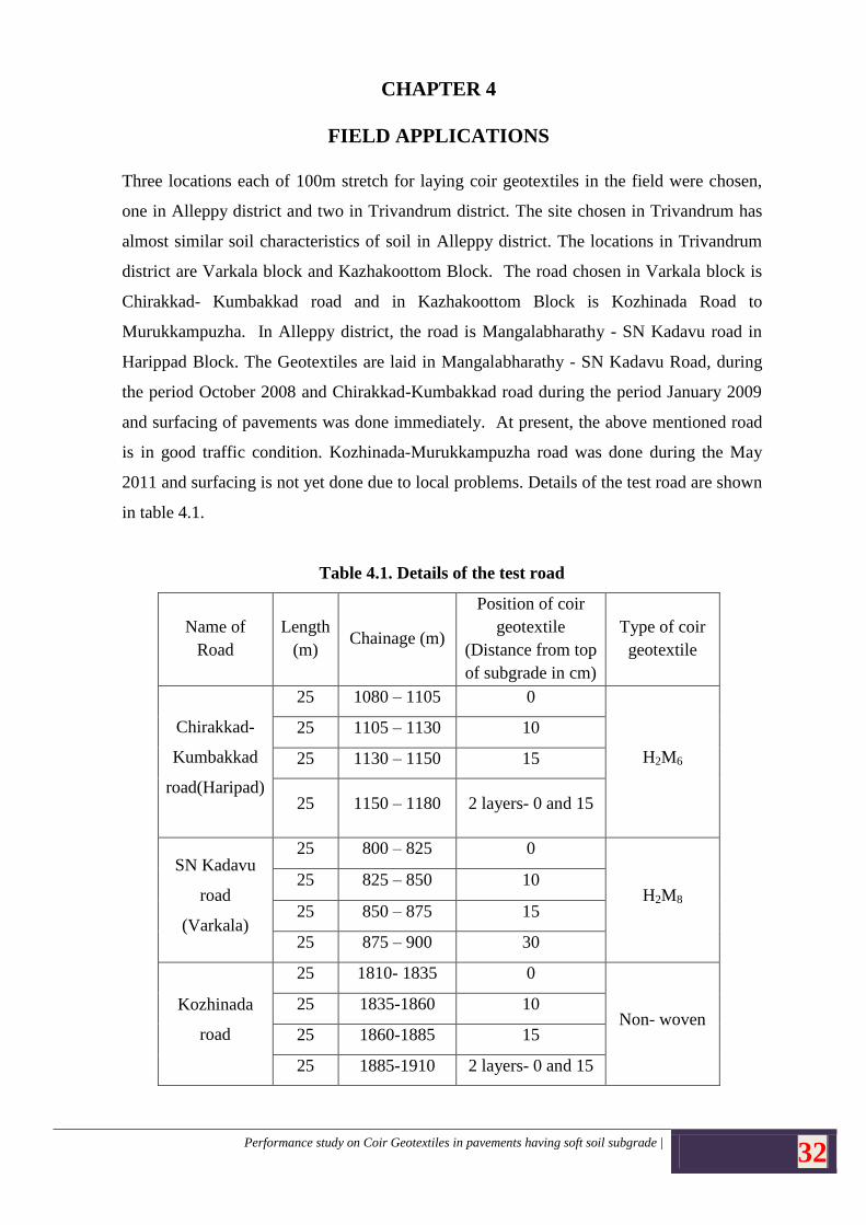
Three locations each of 100m stretch for laying coir geotextiles in the field were chosen,
one in Alleppy district and two in Trivandrum district. The site chosen in Trivandrum has
almost similar soil characteristics of soil in Alleppy district. The locations in Trivandrum
district are Varkala block and Kazhakoottom Block. The road chosen in Varkala block is
Chirakkad- Kumbakkad road and in Kazhakoottom Block is Kozhinada Road to
Murukkampuzha. In Alleppy district, the road is Mangalabharathy - SN Kadavu road in
Harippad Block. The Geotextiles are laid in Mangalabharathy - SN Kadavu Road, during
the period October 2008 and Chirakkad-Kumbakkad road during the period January 2009
and surfacing of pavements was done immediately. At present, the above mentioned road
is in good traffic condition. Kozhinada-Murukkampuzha road was done during the May
2011 and surfacing is not yet done due to local problems. Details of the test road are shown
in table 4.1.
Table 4.1. Details of the test road
Name of
Road
Length
(m) Chainage (m)
Position of coir
geotextile
(Distance from top
of subgrade in cm)
Type of coir
geotextile
Chirakkad-
Kumbakkad
road(Haripad)
25 1080 – 1105 0
H2M6
25 1105 – 1130 10
25 1130 – 1150 15
25 1150 – 1180 2 layers- 0 and 15
SN Kadavu
road
(Varkala)
25 800 – 825 0
H2M8 25 825 – 850 10
25 850 – 875 15
25 875 – 900 30
Kozhinada
road
25 1810- 1835 0
Non- woven 25 1835-1860 10
25 1860-1885 15
25 1885-1910 2 layers- 0 and 15
Performance study on Coir Geotextiles in pavements having soft soil subgrade | 33
3 roads are designed as Road 1, 2 and 3. The details are given below
Test road 1
Location Details
Name of Block: Haripad
Name of Road: Mangala Bharathi – SN Kadavu
The stretches for the 800m to 900m is chosen as the test stretch
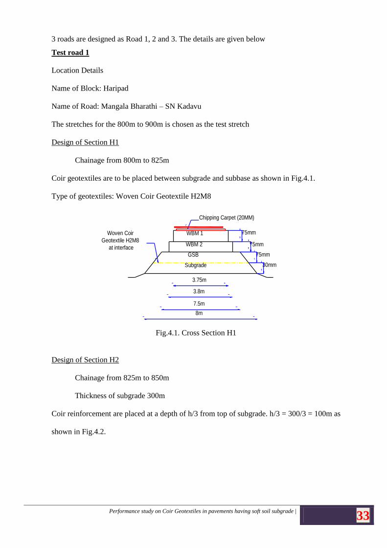
Design of Section H1
Chainage from 800m to 825m
Coir geotextiles are to be placed between subgrade and subbase as shown in Fig.4.1.
Type of geotextiles: Woven Coir Geotextile H2M8
75mm
75mm
75mm
30mm
Chipping Carpet (20MM)
Woven Coir
Geotextile H2M8
at interface
WBM 1
WBM 2
GSB
Subgrade
3.75m
3.8m
7.5m
8m
Fig. 7 Cross Section H1
Fig.4.1. Cross Section H1
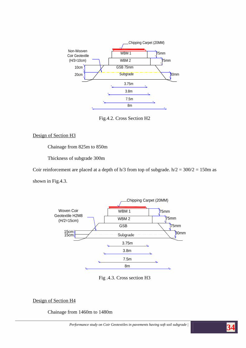
Design of Section H2
Chainage from 825m to 850m
Thickness of subgrade 300m
Coir reinforcement are placed at a depth of h/3 from top of subgrade. h/3 = 300/3 = 100m as
shown in Fig.4.2.
Performance study on Coir Geotextiles in pavements having soft soil subgrade | 34
75mm
75mm
30mm
Chipping Carpet (20MM)
Non-Wooven
Coir Geotextile
(H/3=10cm)
WBM 1
WBM 2
GSB 75mm
Subgrade
3.75m
3.8m
7.5m
8m
Fig. 13 Cross Section V2
20cm
10cm
Fig.4.2. Cross Section H2
Design of Section H3
Chainage from 825m to 850m
Thickness of subgrade 300m
Coir reinforcement are placed at a depth of h/3 from top of subgrade. h/2 = 300/2 = 150m as
shown in Fig.4.3.
75mm
75mm
30mm
Chipping Carpet (20MM)
Woven Coir
Geotextile H2M8
(H/2=15cm)
WBM 1
WBM 2
GSB
Subgrade
3.75m
3.8m
7.5m
8m
Fig. 9 Cross Section H3
75mm
15cm15cm
Fig .4.3. Cross section H3
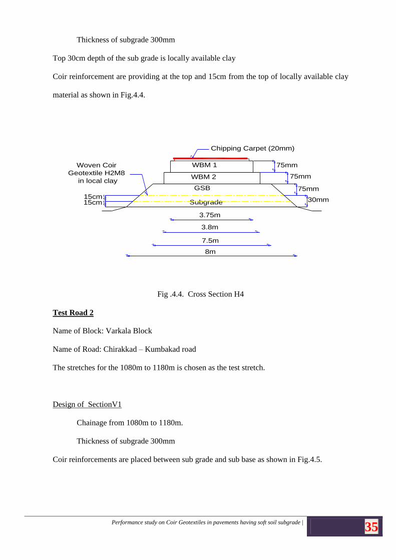
Design of Section H4
Chainage from 1460m to 1480m
Performance study on Coir Geotextiles in pavements having soft soil subgrade | 35
Thickness of subgrade 300mm
Top 30cm depth of the sub grade is locally available clay
Coir reinforcement are providing at the top and 15cm from the top of locally available clay
material as shown in Fig.4.4.
75mm
75mm
30mm
Chipping Carpet (20mm)
Woven Coir
Geotextile H2M8
in local clay
WBM 1
WBM 2
GSB
Subgrade
3.75m
3.8m
7.5m
8m
Fig. 10 Cross Section H4
75mm
15cm15cm
Fig .4.4. Cross Section H4
Test Road 2
Name of Block: Varkala Block
Name of Road: Chirakkad – Kumbakad road
The stretches for the 1080m to 1180m is chosen as the test stretch.
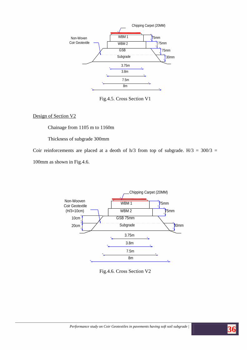
Design of SectionV1
Chainage from 1080m to 1180m.
Thickness of subgrade 300mm
Coir reinforcements are placed between sub grade and sub base as shown in Fig.4.5.
Performance study on Coir Geotextiles in pavements having soft soil subgrade | 36
75mm
75mm
75mm
30mm
Chipping Carpet (20MM)
Non-Woven
Coir Geotextile
WBM 1
WBM 2
GSB
Subgrade
3.75m
3.8m
7.5m
8m
Fig. 12 Cross Section V1
Fig.4.5. Cross Section V1
Design of Section V2
Chainage from 1105 m to 1160m
Thickness of subgrade 300mm
Coir reinforcements are placed at a deoth of h/3 from top of subgrade. H/3 = 300/3 =
100mm as shown in Fig.4.6.
75mm
75mm
30mm
Chipping Carpet (20MM)
Non-Wooven
Coir Geotextile
(H/3=10cm)
WBM 1
WBM 2
GSB 75mm
Subgrade
3.75m
3.8m
7.5m
8m
Fig. 13 Cross Section V2
20cm
10cm
Fig.4.6. Cross Section V2
Performance study on Coir Geotextiles in pavements having soft soil subgrade | 37
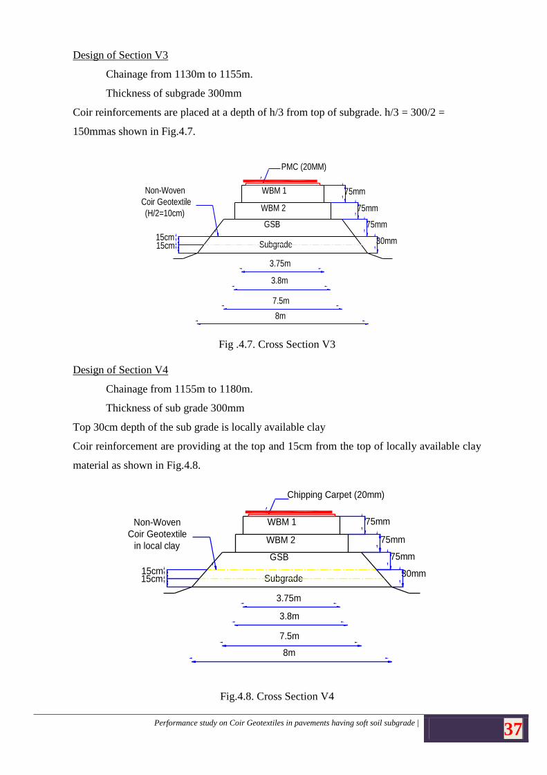
Design of Section V3
Chainage from 1130m to 1155m.
Thickness of subgrade 300mm
Coir reinforcements are placed at a depth of h/3 from top of subgrade. h/3 = 300/2 =
150mmas shown in Fig.4.7.
75mm
75mm
30mm
PMC (20MM)
Non-Woven
Coir Geotextile
(H/2=10cm)
WBM 1
WBM 2
GSB
Subgrade
3.75m
3.8m
7.5m
8m
Fig. 14 Cross Section V3
15cm15cm
75mm
Fig .4.7. Cross Section V3
Design of Section V4
Chainage from 1155m to 1180m.
Thickness of sub grade 300mm
Top 30cm depth of the sub grade is locally available clay
Coir reinforcement are providing at the top and 15cm from the top of locally available clay
material as shown in Fig.4.8.
75mm
75mm
30mm
Chipping Carpet (20mm)
Non-Woven
Coir Geotextile
in local clay
WBM 1
WBM 2
GSB
Subgrade
3.75m
3.8m
7.5m
8m
Fig. 15 Cross Section V4
75mm
15cm15cm
Fig.4.8. Cross Section V4
Performance study on Coir Geotextiles in pavements having soft soil subgrade | 38
Test Road 3
Name of Block: Kazhakoottom
Name of Road: Kozhinada –Murukkampuzha road
The stretches for the 1080m to 1180m is chosen as the test stretch.
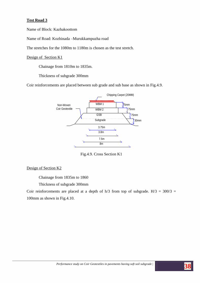
Design of Section K1
Chainage from 1810m to 1835m.
Thickness of subgrade 300mm
Coir reinforcements are placed between sub grade and sub base as shown in Fig.4.9.
75mm
75mm
75mm
30mm
Chipping Carpet (20MM)
Non-Woven
Coir Geotextile
WBM 1
WBM 2
GSB
Subgrade
3.75m
3.8m
7.5m
8m
Fig. 12 Cross Section V1
Fig.4.9. Cross Section K1
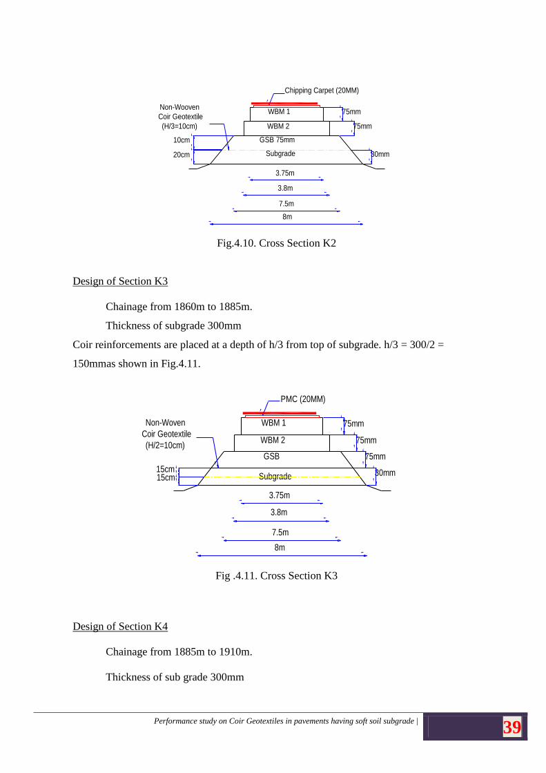
Design of Section K2
Chainage from 1835m to 1860
Thickness of subgrade 300mm
Coir reinforcements are placed at a depth of h/3 from top of subgrade. H/3 = 300/3 =
100mm as shown in Fig.4.10.
Performance study on Coir Geotextiles in pavements having soft soil subgrade | 39
75mm
75mm
30mm
Chipping Carpet (20MM)
Non-Wooven
Coir Geotextile
(H/3=10cm)
WBM 1
WBM 2
GSB 75mm
Subgrade
3.75m
3.8m
7.5m
8m
Fig. 13 Cross Section V2
20cm
10cm
Fig.4.10. Cross Section K2
Design of Section K3
Chainage from 1860m to 1885m.
Thickness of subgrade 300mm
Coir reinforcements are placed at a depth of h/3 from top of subgrade. h/3 = 300/2 =
150mmas shown in Fig.4.11.
75mm
75mm
30mm
PMC (20MM)
Non-Woven
Coir Geotextile
(H/2=10cm)
WBM 1
WBM 2
GSB
Subgrade
3.75m
3.8m
7.5m
8m
Fig. 14 Cross Section V3
15cm15cm
75mm
Fig .4.11. Cross Section K3
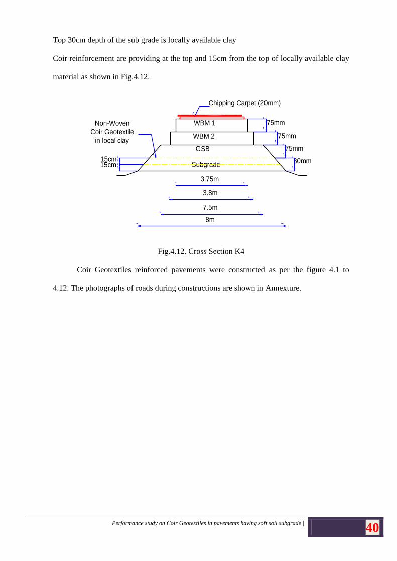
Design of Section K4
Chainage from 1885m to 1910m.
Thickness of sub grade 300mm
Performance study on Coir Geotextiles in pavements having soft soil subgrade | 40
Top 30cm depth of the sub grade is locally available clay
Coir reinforcement are providing at the top and 15cm from the top of locally available clay
material as shown in Fig.4.12.
75mm
75mm
30mm
Chipping Carpet (20mm)
Non-Woven
Coir Geotextile
in local clay
WBM 1
WBM 2
GSB
Subgrade
3.75m
3.8m
7.5m
8m
Fig. 15 Cross Section V4
75mm
15cm15cm
Fig.4.12. Cross Section K4
Coir Geotextiles reinforced pavements were constructed as per the figure 4.1 to
4.12. The photographs of roads during constructions are shown in Annexture.
Performance study on Coir Geotextiles in pavements having soft soil subgrade | 41
CHAPTER 5
PERFORMANCE EVALUATION
Performance study was carried out by visual examination, deflection measurement
by Benkelman Beam, International Roughness index using Merlin test and Skid resistance
using bump indicator.
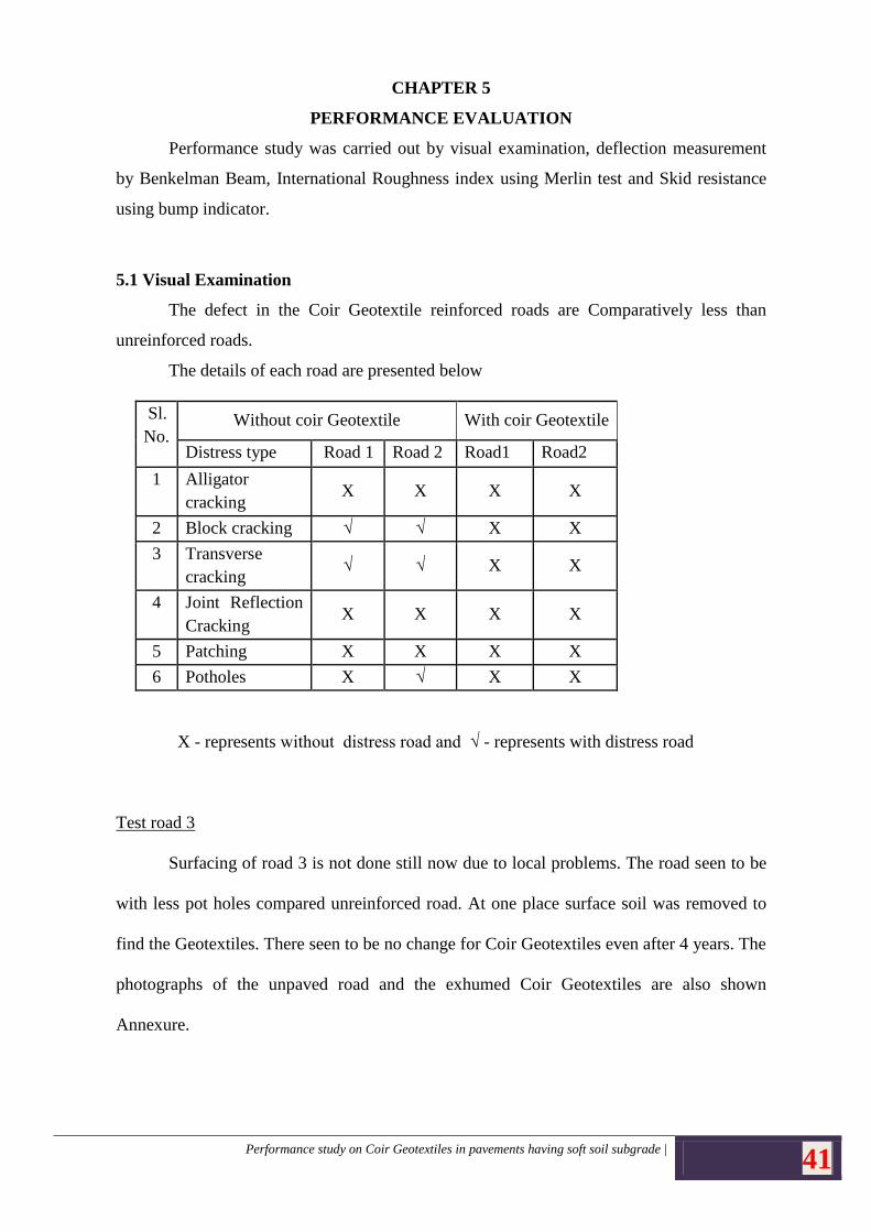
5.1 Visual Examination
The defect in the Coir Geotextile reinforced roads are Comparatively less than
unreinforced roads.
The details of each road are presented below
Sl.
No. Without coir Geotextile With coir Geotextile
Distress type Road 1 Road 2 Road1 Road2
1 Alligator
cracking X X X X
2 Block cracking √ √ X X
3 Transverse
cracking √ √ X X
4 Joint Reflection
Cracking X X X X
5 Patching X X X X
6 Potholes X √ X X
X - represents without distress road and √ - represents with distress road
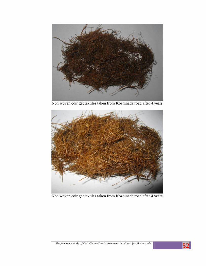
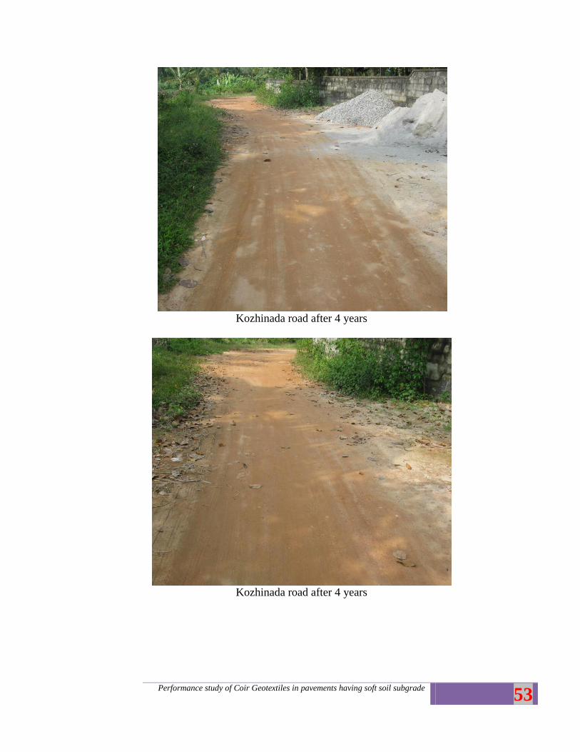
Test road 3
Surfacing of road 3 is not done still now due to local problems. The road seen to be
with less pot holes compared unreinforced road. At one place surface soil was removed to
find the Geotextiles. There seen to be no change for Coir Geotextiles even after 4 years. The
photographs of the unpaved road and the exhumed Coir Geotextiles are also shown
Annexure.
Performance study on Coir Geotextiles in pavements having soft soil subgrade | 42
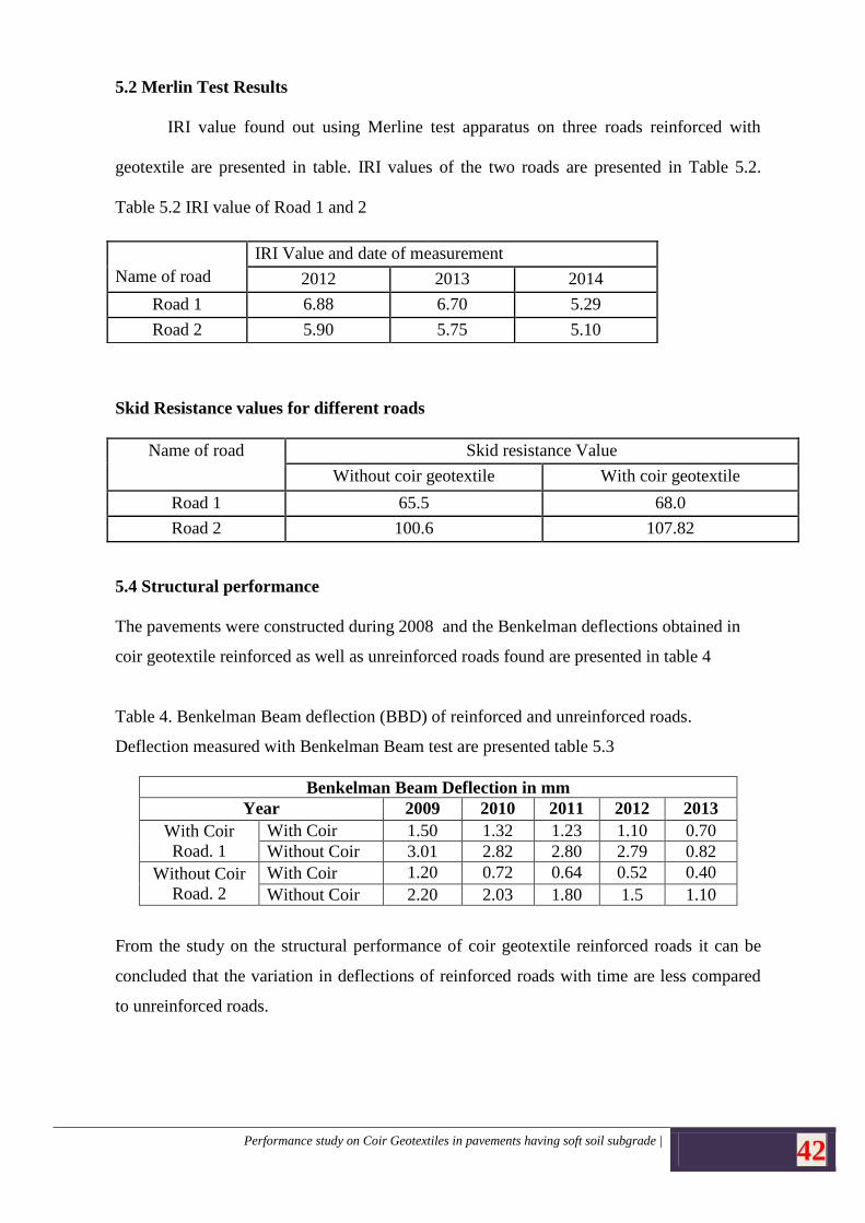
5.2 Merlin Test Results
IRI value found out using Merline test apparatus on three roads reinforced with
geotextile are presented in table. IRI values of the two roads are presented in Table 5.2.
Table 5.2 IRI value of Road 1 and 2
Skid Resistance values for different roads
Name of road Skid resistance Value
Without coir geotextile With coir geotextile
Road 1 65.5 68.0
Road 2 100.6 107.82
5.4 Structural performance
The pavements were constructed during 2008 and the Benkelman deflections obtained in
coir geotextile reinforced as well as unreinforced roads found are presented in table 4
Table 4. Benkelman Beam deflection (BBD) of reinforced and unreinforced roads.
Deflection measured with Benkelman Beam test are presented table 5.3
Benkelman Beam Deflection in mm
Year 2009 2010 2011 2012 2013
With Coir
Road. 1
With Coir 1.50 1.32 1.23 1.10 0.70
Without Coir 3.01 2.82 2.80 2.79 0.82
Without Coir
Road. 2
With Coir 1.20 0.72 0.64 0.52 0.40
Without Coir 2.20 2.03 1.80 1.5 1.10
From the study on the structural performance of coir geotextile reinforced roads it can be
concluded that the variation in deflections of reinforced roads with time are less compared
to unreinforced roads.
Name of road
IRI Value and date of measurement
2012 2013 2014
Road 1 6.88 6.70 5.29
Road 2 5.90 5.75 5.10
Performance study on Coir Geotextiles in pavements having soft soil subgrade | 43
Chapter 6
Conclusions
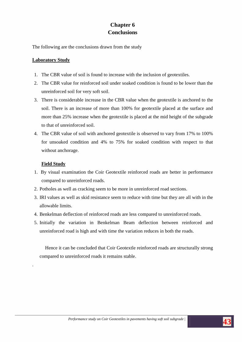
The following are the conclusions drawn from the study
Laboratory Study
1. The CBR value of soil is found to increase with the inclusion of geotextiles.
2. The CBR value for reinforced soil under soaked condition is found to be lower than the
unreinforced soil for very soft soil.
3. There is considerable increase in the CBR value when the geotextile is anchored to the
soil. There is an increase of more than 100% for geotextile placed at the surface and
more than 25% increase when the geotextile is placed at the mid height of the subgrade
to that of unreinforced soil.
4. The CBR value of soil with anchored geotextile is observed to vary from 17% to 100%
for unsoaked condition and 4% to 75% for soaked condition with respect to that
without anchorage.
Field Study
1. By visual examination the Coir Geotextile reinforced roads are better in performance
compared to unreinforced roads.
2. Potholes as well as cracking seem to be more in unreinforced road sections.
3. IRI values as well as skid resistance seem to reduce with time but they are all with in the
allowable limits.
4. Benkelman deflection of reinforced roads are less compared to unreinforced roads.
5. Initially the variation in Benkelman Beam deflection between reinforced and
unreinforced road is high and with time the variation reduces in both the roads.
Hence it can be concluded that Coir Geotextle reinforced roads are structurally strong
compared to unreinforced roads it remains stable.
.
Performance study on Coir Geotextiles in pavements having soft soil subgrade | 44
Paper Published
Greeshma P G, Mariamma Joseph and Sheela Evangeline Y, 2010:- “Effect of Anchorage
on Coir Geotextile Reinforcement” Proceedings of International Conference on
Technological Trends (ICTT 2010), CET, TVM
References
[1] Ajitha, B., Jayadeep, T., 1997. . “Interfacial frictional properties of geotextiles and
biomats”.,in: Proceedings of Indian Geotechnical Conference, Vadodara, India, Vol.1, pp.
287-290.
[2] Anderson, P., Killeavy, M., 1989. “Geotextiles and geogrids-cost effective alternate
materials for pavement design and construction” In: Geosynthetics’89, San Diego,
USA, vol. 2, 353-364
[3] Babu, K.K., Beena, K.S., Raji, A.K., 2008.”Design of Coir Geotextile
reinforced Road using IRC method”. Highway Research Journal, Special Issue
[4] Cancelli, A., Montanelli, F., 1999. “In-ground test for geosynthetic reinforced flexible
paved roads”. Proceedings of Geosynthetics ’99, Vol. 2, Boston, USA, pp. 863-879.
[5] Chauhan, M.S., Mittal, S., Mohanty, B., 2008. Performance evaluation of silty sand
subgrade reinforced with fly ash and fibre. Geotextiles and Geomembranes 26 (5),429-435.
[6] Datye. K. R, Gore. V. N., (1994) “Application of natural geotextiles and related
products” Geotextiles and Geomembrance 13,371-388
[7] Fannin, R.J., Sigurdsson, O., 1996 “ Field observations on stabilization of unpaved roads
with geotextiles” Journal of Geotechnical Engineering, ASCE. 26(7): 544-553.
[8] Giroud, J.P, Noiray, L, 1981. “Geotextile reinforced unpaved road design” Journal of
Geotechnical Engineering ASCE 107 (9), 1233–1254.
[9] IRC: 81-1997 Guidelines for Strengthening of Flexible Road Pavements using
Benkelman Beam Deflection technique.
[10] IRC : SP 72 – 2007 Guidelines for the design of flexible pavements for Low volume
Rural Roads.
[11] IS: 2720(Part 16) – 1979, Methods of Test for Soils: Determination of California
Bearing Ratio.
[12] IS 2720 (Part 5)-1985, Methods of Test for Soils: Determination of Atterberg Limits.
Performance study on Coir Geotextiles in pavements having soft soil subgrade | 45
[13] IS 2720 (Part 8)- 1983, Methods of Test for Soils: Determination of Water Content –
Dry Density Relation using Heavy Compaction.
[14] IS: 15868 (Parts 1 to 6) – 2010. Methods of test natural fibre geotextiles (Jute
geotextile and coir Bhoovastra)
[15] Khanna,S.K, Justo. C.E.G, “Highway Engineering”, published by New Chand and
Bros., Roorkee, Eighth Edition, 2009.
[16]M.V.L.R..Anjaneyulu,“Evaluation of Pavement Performance”
[17] Perkins, S.W., 1999a. Geosynthetic reinforcement of flexible pavements: laboratory
based pavement test sections.
Final Report FHWA/MT-99-001/8138, State ofMontana Department of Transportation,
MT, USA, 140 p.
[18] Perkins, S.W., 1999b. Mechanical response of geosynthetic-reinforced flexible
pavements. Geosynthetics International 6 (5), 347-382
[19] Rao. G. V, Balan. K, (2000) “coir geotextiles Emerging trends”. The Kerala state coir
corporation LTD (publishers) Alappuzha, Kerala.
[20] Rawal, A., Anandjiwala, R., 2007. Comparative study between needle punched
nonwoven geotextile structures made from flax and polyester fibres. Geotextiles and
Geomembranes 25 (1), 61-65.
[21] Sankariah, B., Narahari, R., 1988.” Bearing capacity of reinforced sand beds”
In:Proc..on First Indian Geotextile Conference on Reinforced soil and geotextiles,Bombay,
India, pp. C11-C13.
[22] Sarsby, R.W., 2007. Use of ’Limited Life Geotextiles’ (LLGs) for basal reinforcement
of embankments built on soft clay. Geotextiles and Geomembranes 25 (4-5),302-310.
[23] Senthil, K.P., Pandiammal, D.S., 2011. Effect of needle punched nonwoven coir and
jute geotextiles on CBR strength of soft subgrade, ARPN Journal of Engineering and
Applied Sciences, Vol. 6, no. 11, November 2011.
[24] Som, N., Sahu, R.B., 1999. Bearing capacity of a geotextile-reinforced unpaved road
as a function of deformation - a model study. Geosynthetics International 6 (1), 1-17.
[25] Subaida, E.A., Chandrakaran, S., Sankar, N., 2008. “Experimental investigations on
tensile and pullout behaviour of woven coir geotextiles”. Geotextiles and Geomembranes27,
pp. 204-21
Performance study of Coir Geotextiles in pavements having soft soil subgrade
46
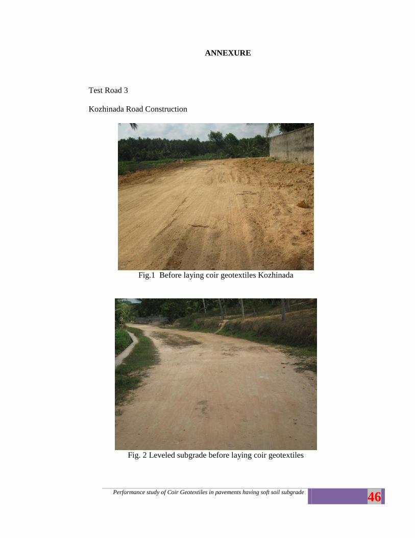
ANNEXURE
Test Road 3
Kozhinada Road Construction
Fig.1 Before laying coir geotextiles Kozhinada
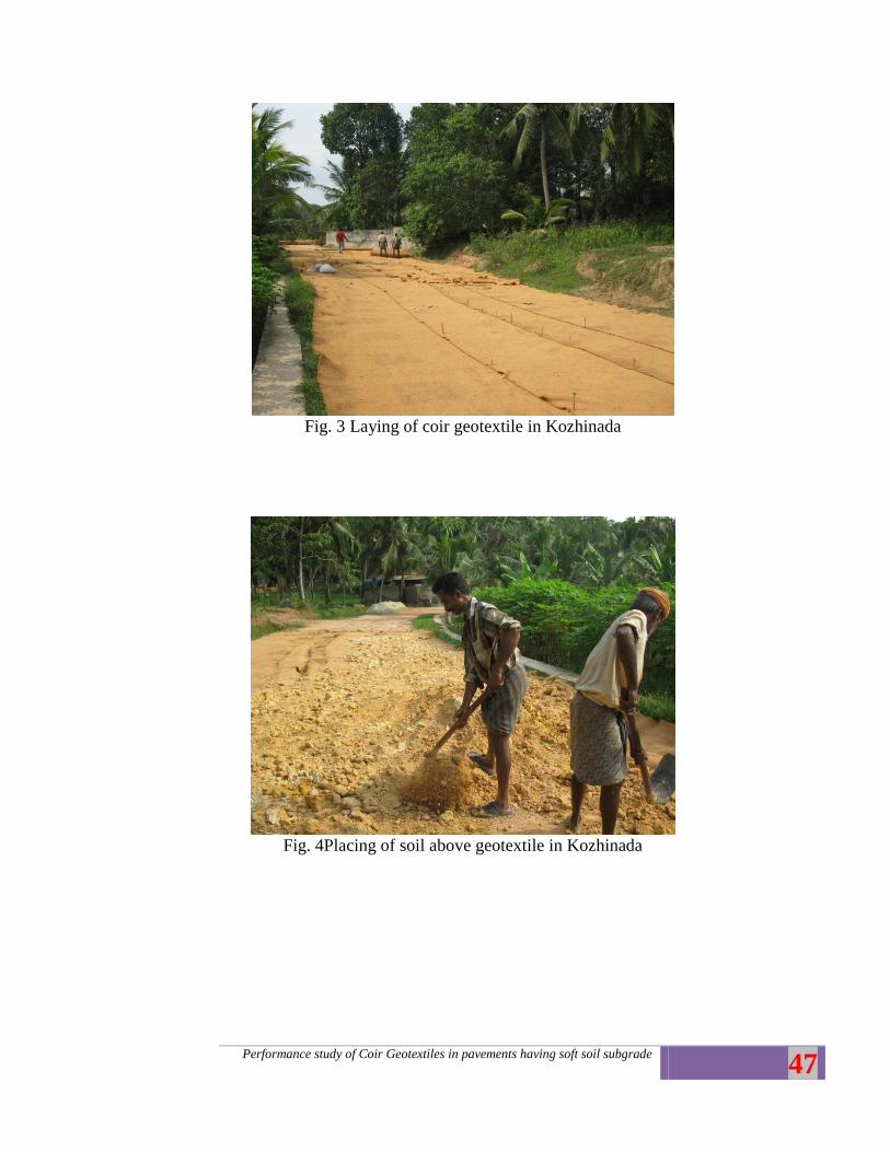
Fig. 2 Leveled subgrade before laying coir geotextiles
Performance study of Coir Geotextiles in pavements having soft soil subgrade
47
Fig. 3 Laying of coir geotextile in Kozhinada
Fig. 4Placing of soil above geotextile in Kozhinada
Performance study of Coir Geotextiles in pavements having soft soil subgrade
48
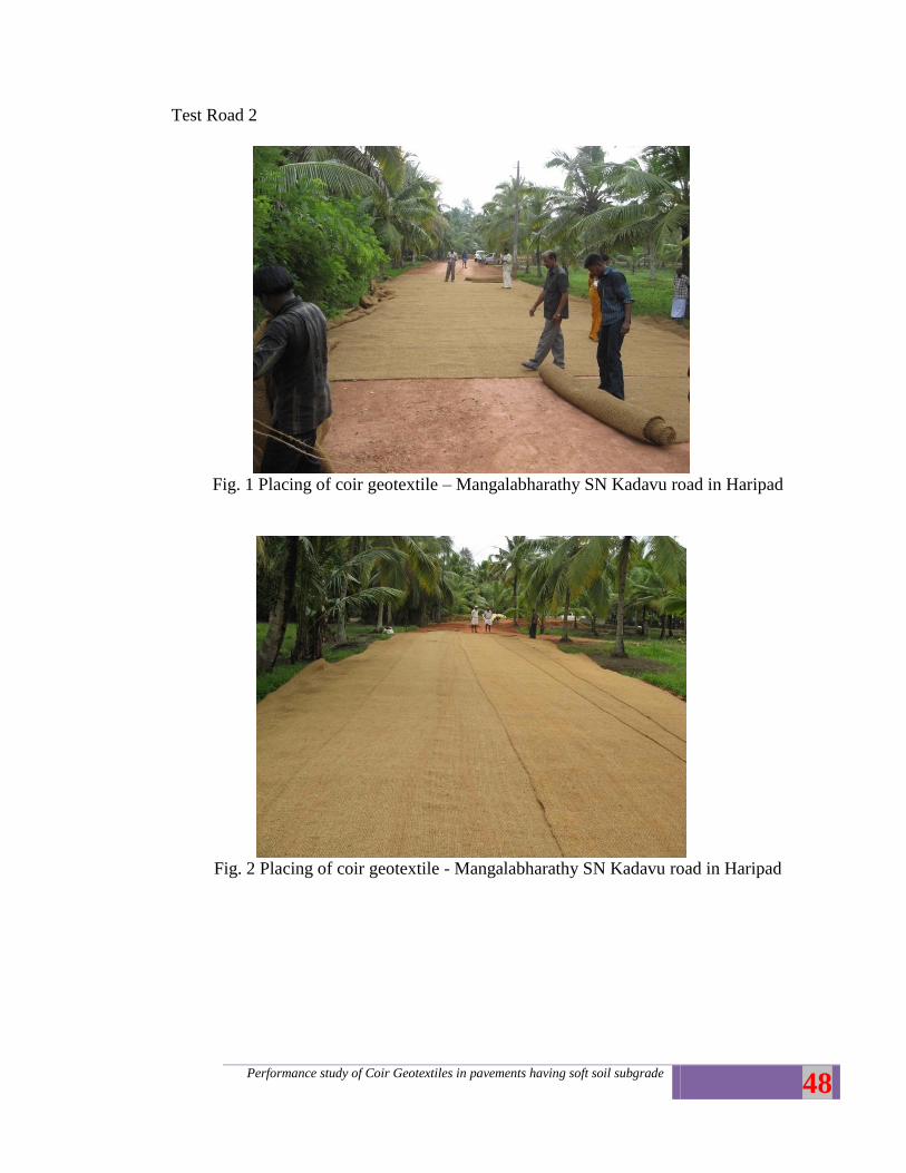
Test Road 2
Fig. 1 Placing of coir geotextile – Mangalabharathy SN Kadavu road in Haripad
Fig. 2 Placing of coir geotextile - Mangalabharathy SN Kadavu road in Haripad
Performance study of Coir Geotextiles in pavements having soft soil subgrade
49
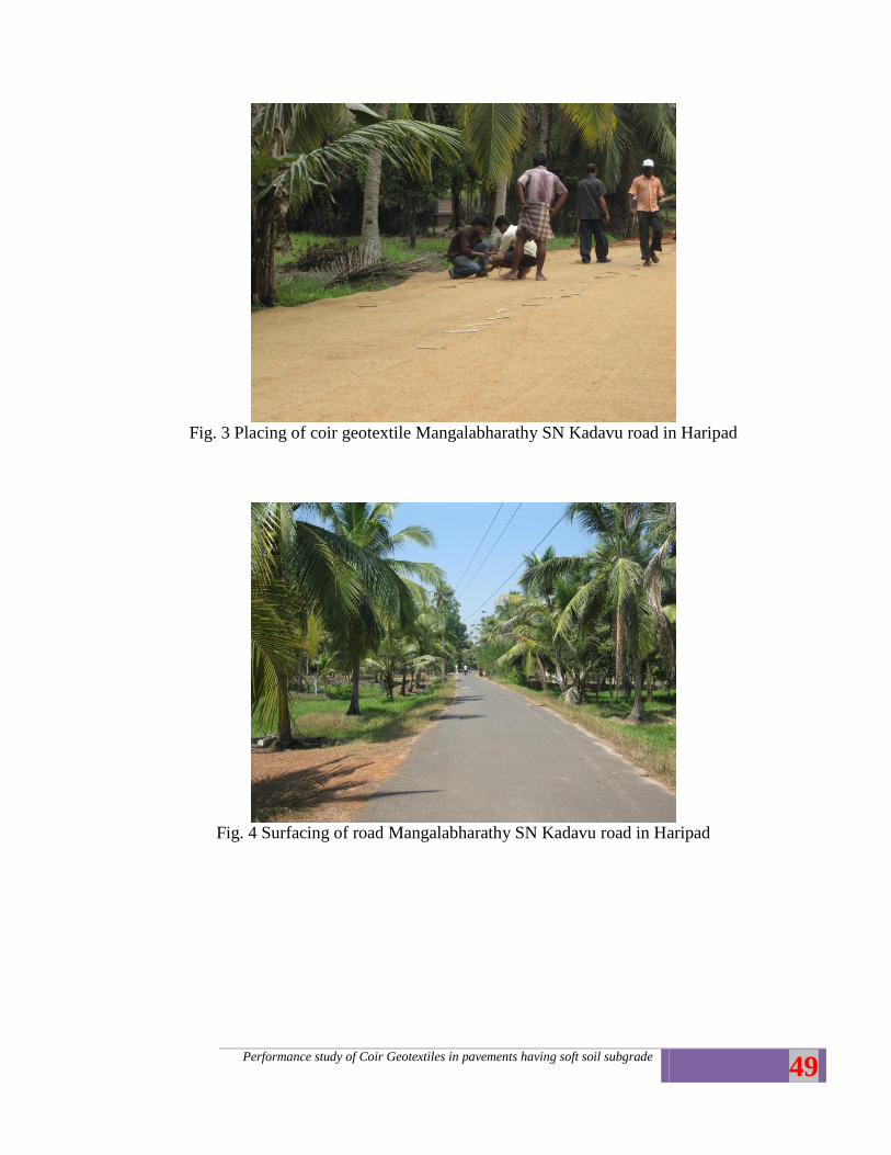
Fig. 3 Placing of coir geotextile Mangalabharathy SN Kadavu road in Haripad
Fig. 4 Surfacing of road Mangalabharathy SN Kadavu road in Haripad
Performance study of Coir Geotextiles in pavements having soft soil subgrade
50
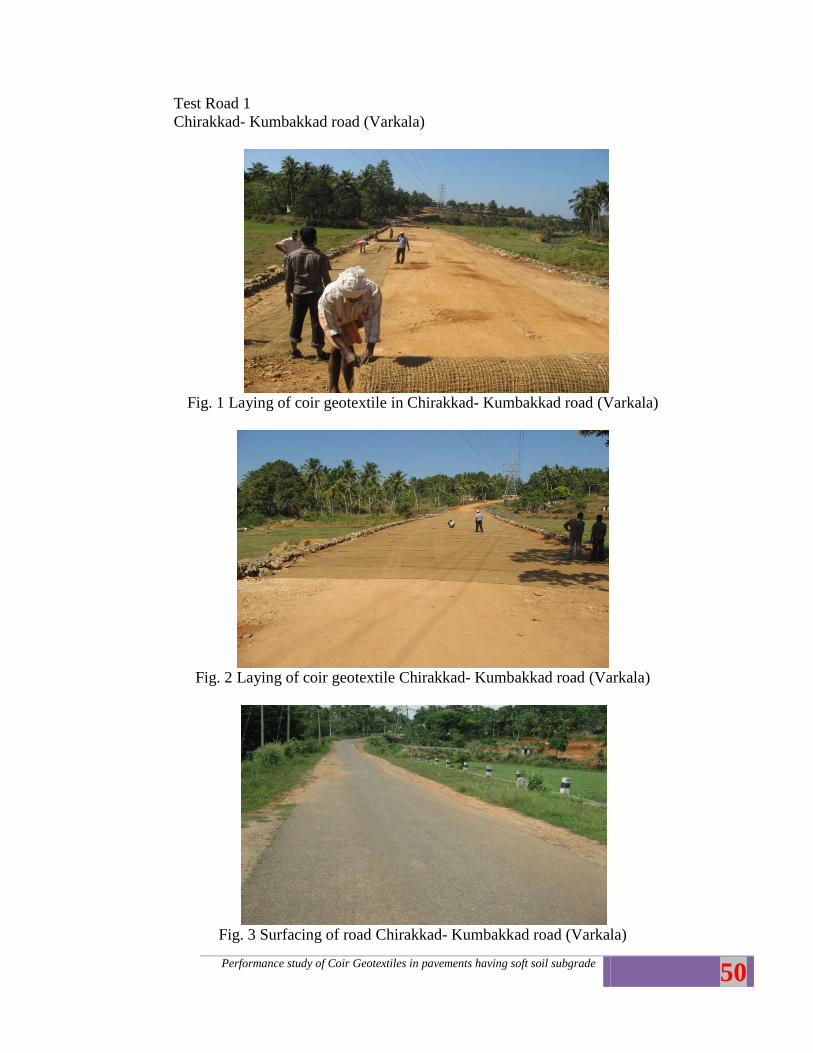
Test Road 1
Chirakkad- Kumbakkad road (Varkala)
Fig. 1 Laying of coir geotextile in Chirakkad- Kumbakkad road (Varkala)
Fig. 2 Laying of coir geotextile Chirakkad- Kumbakkad road (Varkala)
Fig. 3 Surfacing of road Chirakkad- Kumbakkad road (Varkala)
Performance study of Coir Geotextiles in pavements having soft soil subgrade
51
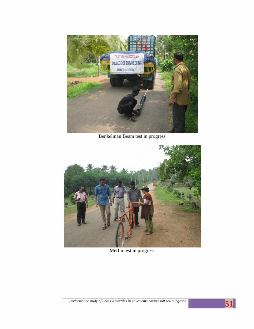
Benkelman Beam test in progress
Merlin test in progress
Performance study of Coir Geotextiles in pavements having soft soil subgrade
52
Non woven coir geotextiles taken from Kozhinada road after 4 years
Non woven coir geotextiles taken from Kozhinada road after 4 years
Performance study of Coir Geotextiles in pavements having soft soil subgrade
53
Kozhinada road after 4 years
Kozhinada road after 4 years