performance of the l- and p-band subsystems of the f-sar ... · another important calibration...
TRANSCRIPT
Performance of the L- and P-band Subsystems of the F-SAR Airborne SAR InstrumentA. Reigber, M. Jäger, J. Fischer, R. Horn, R. Scheiber, P. Prats and A. NottensteinerMicrowaves and Radar Institute, German Aerospace Center (DLR), Germany
Abstract
The F-SAR airborne SAR instrument represents the successor of the E-SAR system of the German Aerospace Center (DLR), which has been extensively used in the last three decades. Its development was triggered by the current demand for data being simultaneously acquired at different wavelengths and polarisations, as well as by the demand for very high resolution in the order of decimetres. F-SAR is a modular development utilising the most modern hardware and commercial off the shelf components. As for E-SAR DLR’s Dornier DO228-212 aircraft is the first choice as platform for the new system.
Although the F-SAR system is still under development, since some years it is already taking over some of the operational duties of the old E-SAR system. With the recently completed L-band and P-band subsystems, F-SAR is now ready for fully replacing the E-SAR. This paper presents the new L-band subsystems and analyses its performance based on fully polarimetric imagery acquired during recent system test and calibration campaigns. The maiden flight of the new F-SAR P-band system has been postponed to spring 2012, first results will be shown in the conference presentation. Special emphasis is placed on the system calibration and the associated quality control including the achieved spatial resolution and radiometric accuracy in the different bands.
1 F-SAR instrument design and status
F-SAR is designed to operate fully polarimetrically at X-, C-, S-, L- and P-bands and will provide single-pass polarimetric interferometric capabilities in X- and S-bands. Repeat-pass PolInSAR is a standard measurement mode for the other bands. Range resolution is determined by the available system bandwidth. While components limit system bandwidth to 100MHz at P-band, a step-frequency approach is adopted to achieve up to 760MHz effective signal bandwidth at X-band to satisfy the requirement for very high resolution [2]. An overview of the general design parameters can be found in Tab. 1.
Tab.1: F-SAR technical characteristics.
Band X C S L P1 / P2
RF (GHz) 9.6 5.3 3.25 1.325 0.35/0.45
Bw [MHz] 760 400 300 150 100/50
PRF [kHz] 5 5 5 10 10
PT [kW] 2.5 2.2 2.2 0.9 0.9
Rg res [m] 0.2 0.4 0.5 1.0 1.5
Az res. [m] 0.2 0.3 0.35 0.4 1.5
Channels 4 2 2 2 2
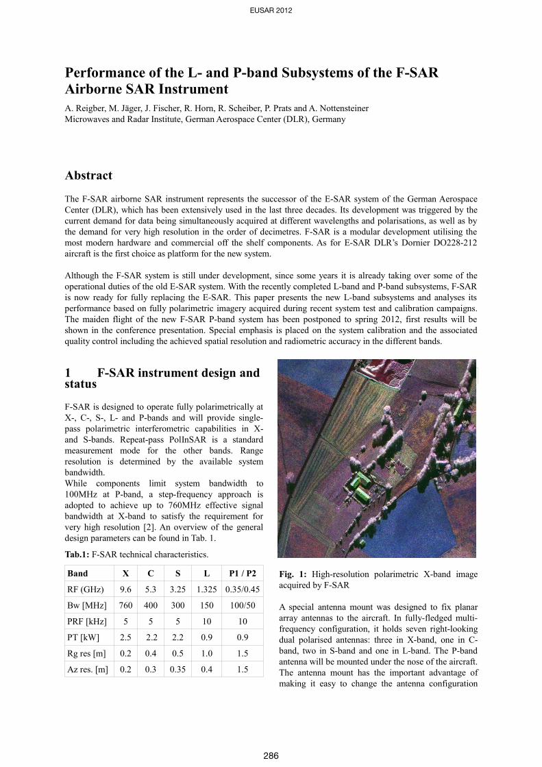
Fig. 1: High-resolution polarimetric X-band image acquired by F-SAR
A special antenna mount was designed to fix planar array antennas to the aircraft. In fully-fledged multi-frequency configuration, it holds seven right-looking dual polarised antennas: three in X-band, one in C-band, two in S-band and one in L-band. The P-band antenna will be mounted under the nose of the aircraft. The antenna mount has the important advantage of making it easy to change the antenna configuration
EUSAR 2012
286
and to mount other antennas without necessitating additional individual airworthiness certification procedures. The nominal antenna configuration provides three single-pass interferometers: across track (XTI) in S-band and X-band, and along track (ATI) in X-band. The mechanical baselines are approx. 1.60m (XTI) and approx. 85cm (ATI). Special configurations, such as a GMTI antenna array in the top frame, are planned [3]. For regular Earth observation purposes the radar covers an off-nadir angle range of 25 to 60 degrees at altitudes of up to 6000m above sea level, which is the maximum operating altitude of the DO228 aircraft. In special applications, other off-nadir angle ranges, such as 60 to 85 degrees for long stand-off imaging or 0 to 25 degrees for sounding or steep incidence applications are feasible. Currently, all subsystems are completed and undergoing an optimisation of their performance. While the X-, C- and S-band system have already been since a while operated in flight using an experimental antenna pod, the L-band and the P-band system were just recently completed - the L-band in spring 2011 and the P-band in autumn 2011. While the L-band subsystem is in operation since summer 2011, it was necessary to postpone the P-band maiden flight to spring 2012. First results will be shown at the conference.It is planned to fully equip the final antenna hold with the other antennas (X-, C- and S-band) between end of 2011 and mid of 2012. This will allow to operate the X- and S-band single-pass PolInSAR set-ups, which have not been possible to date with the experimental antenna pod. This will finally complete the F-SAR as it is currently projected.
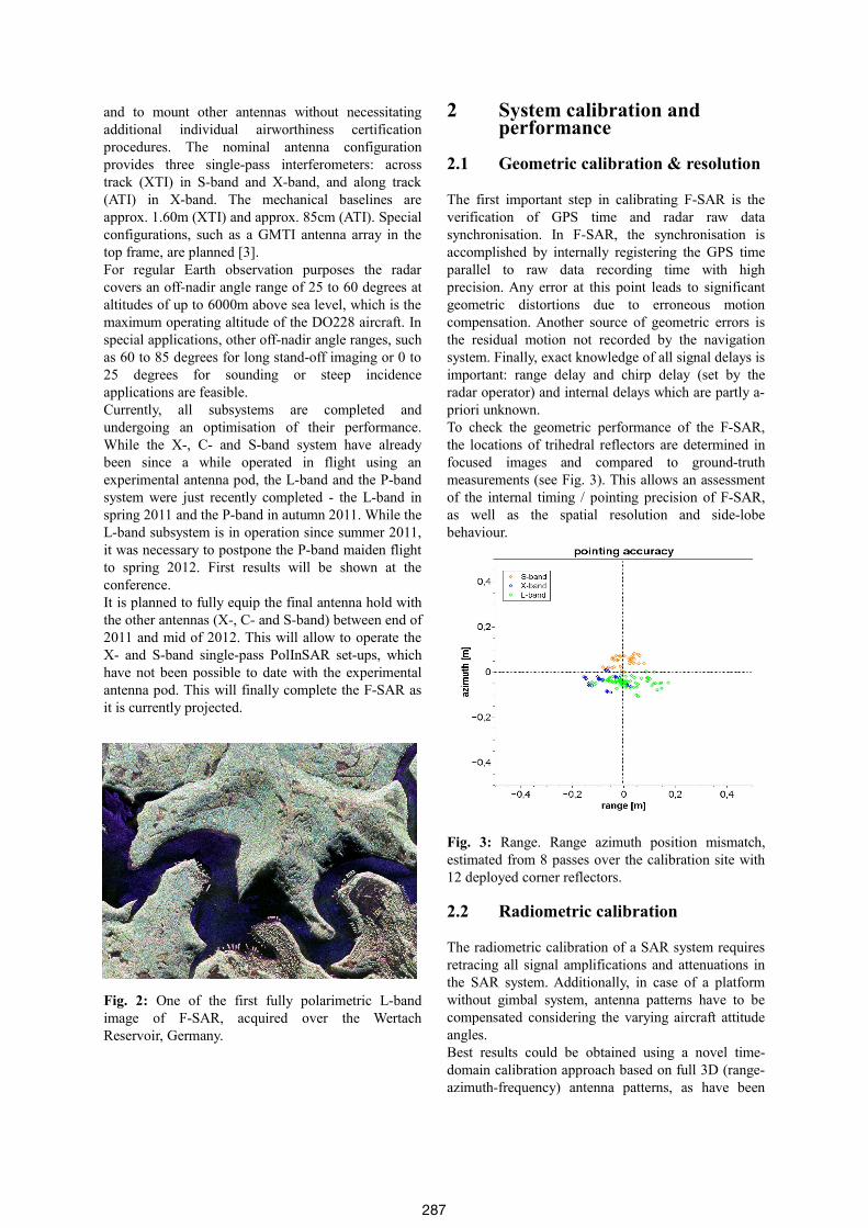
Fig. 2: One of the first fully polarimetric L-band image of F-SAR, acquired over the Wertach Reservoir, Germany.
2 System calibration and performance
2.1 Geometric calibration & resolution
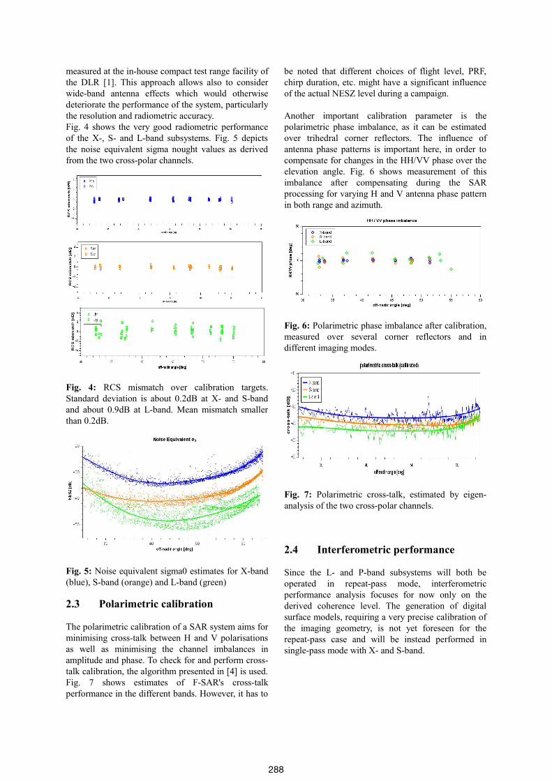
The first important step in calibrating F-SAR is the verification of GPS time and radar raw data synchronisation. In F-SAR, the synchronisation is accomplished by internally registering the GPS time parallel to raw data recording time with high precision. Any error at this point leads to significant geometric distortions due to erroneous motion compensation. Another source of geometric errors is the residual motion not recorded by the navigation system. Finally, exact knowledge of all signal delays is important: range delay and chirp delay (set by the radar operator) and internal delays which are partly a-priori unknown.To check the geometric performance of the F-SAR, the locations of trihedral reflectors are determined in focused images and compared to ground-truth measurements (see Fig. 3). This allows an assessment of the internal timing / pointing precision of F-SAR, as well as the spatial resolution and side-lobe behaviour.
Fig. 3: Range. Range azimuth position mismatch, estimated from 8 passes over the calibration site with 12 deployed corner reflectors.
2.2 Radiometric calibration
The radiometric calibration of a SAR system requires retracing all signal amplifications and attenuations in the SAR system. Additionally, in case of a platform without gimbal system, antenna patterns have to be compensated considering the varying aircraft attitude angles. Best results could be obtained using a novel time-domain calibration approach based on full 3D (range-azimuth-frequency) antenna patterns, as have been
287
measured at the in-house compact test range facility of the DLR [1]. This approach allows also to consider wide-band antenna effects which would otherwise deteriorate the performance of the system, particularly the resolution and radiometric accuracy. Fig. 4 shows the very good radiometric performance of the X-, S- and L-band subsystems. Fig. 5 depicts the noise equivalent sigma nought values as derived from the two cross-polar channels.
Fig. 4: RCS mismatch over calibration targets. Standard deviation is about 0.2dB at X- and S-band and about 0.9dB at L-band. Mean mismatch smaller than 0.2dB.
Fig. 5: Noise equivalent sigma0 estimates for X-band (blue), S-band (orange) and L-band (green)
2.3 Polarimetric calibration
The polarimetric calibration of a SAR system aims for minimising cross-talk between H and V polarisations as well as minimising the channel imbalances in amplitude and phase. To check for and perform cross-talk calibration, the algorithm presented in [4] is used. Fig. 7 shows estimates of F-SAR's cross-talk performance in the different bands. However, it has to
be noted that different choices of flight level, PRF, chirp duration, etc. might have a significant influence of the actual NESZ level during a campaign.
Another important calibration parameter is the polarimetric phase imbalance, as it can be estimated over trihedral corner reflectors. The influence of antenna phase patterns is important here, in order to compensate for changes in the HH/VV phase over the elevation angle. Fig. 6 shows measurement of this imbalance after compensating during the SAR processing for varying H and V antenna phase pattern in both range and azimuth.
Fig. 6: Polarimetric phase imbalance after calibration, measured over several corner reflectors and in different imaging modes.
Fig. 7: Polarimetric cross-talk, estimated by eigen-analysis of the two cross-polar channels.
2.4 Interferometric performance
Since the L- and P-band subsystems will both be operated in repeat-pass mode, interferometric performance analysis focuses for now only on the derived coherence level. The generation of digital surface models, requiring a very precise calibration of the imaging geometry, is not yet foreseen for the repeat-pass case and will be instead performed in single-pass mode with X- and S-band.
288
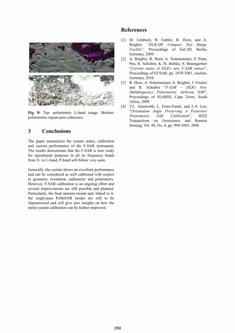
Fig. 8: Top: polatrimtric L-band image. Bottom: polarimetric repeat-pass coherence.
3 Conclusions
The paper summarises the system status, calibration and current performance of the F-SAR instrument. The results demonstrate that the F-SAR is now ready for operational purposes in all its frequency bands from X- to L-band. P-band will follow very soon.
Generally, the system shows an excellent performance and can be considered as well calibrated with respect to geometry, resolution, radiometry and polarimetry. However, F-SAR calibration is an ongoing effort and several improvements are still possible and planned. Particularly, the final antenna mount and, linked to it, the single-pass PolInSAR modes are still to be characterised and will give new insights on how the entire system calibration can be further improved.
References
[1] M. Limbach, B. Gabler, R. Horn, and A. Reigber: “DLR-HR Compact Test Range Facility”, Proceedings of EuCAP, Berlin, Germany, 2009
[2] A. Reigber, R. Horn, A. Nottensteiner, P. Prats, Pau, R. Scheiber, K.-H. Bethke, S. Baumgartner “Current status of DLR’s new F-SAR sensor”, Proceedings of EUSAR, pp. 1078-1081, Aachen, Germany, 2010
[3] R. Horn, A. Nottensteiner, A. Reigber, J. Fischer and R. Scheiber “F-SAR – DLR’s New Multifrequency Polarimetric Airborne SAR”, Proceedings of IGARSS, Cape Town, South Africa, 2009
[4] T.L. Ainsworth, L. Ferro-Famil, and J.-S. Lee: "Orientation Angle Preserving A Posteriori Polarimetric SAR Calibration", IEEE Transactions on Geoscience and Remote Sensing, Vol. 44, No. 4, pp. 994-1003, 2006
289