performance of distributed multiple viscoelastic tuned ... the floor response level to an acceptable...
TRANSCRIPT

1. INTRODUCTIONServiceability rather than strength is the most criticaldesign requirement for vibration-vulnerable floorconstruction. Modern floor systems are being designedand constructed with longer spans owing to the need forlarger column-free spaces in office and commercialretail buildings. The advances in high-strengthmaterials and lightweight construction technologies arealso altering the dynamic characteristics of floorsystems.
Changes in modern office layouts associated with theremoval of full height partitions, heavy filing cabinets,large bookshelves and other architectural componentsresult in a reduction of both load and damping. Hewitt
Advances in Structural Engineering Vol. 15 No. 3 2012 547
Performance of Distributed Multiple Viscoelastic
Tuned Mass Dampers for Floor Vibration Applications
T.H. Nguyen1,*, I. Saidi1, E.F. Gad1, J.L. Wilson1 and N. Haritos2
1Faculty of Engineering and Industrial Sciences, Swinburne University of Technology, VIC 3122, Australia2Department of Infrastructure Engineering, The University of Melbourne, VIC 3010, Australia
(Received: 24 January 2011; Received revised form: 17 June 2011; Accepted: 22 August 2011)
Abstract: Floor vibration due to human activities is becoming a significant concern todesigners and developers of long span lightweight floor systems. Modern office floorsare now constructed with longer spans and lighter structural members. Actual officedead loads and floor damping are significantly lower than what they were in the past,increasing the potential for annoying floor vibration. Traditional techniques to reducevibrations through structural modifications have some serious shortcomings,especially with existing structures. This paper discusses the development of aninnovative configuration for a tuned mass damper (TMD) using viscoelastic materialin rectifying problematic floors. General analytical formulae to predict the response ofa floor fitted with multiple identical TMDs are developed. Experimental and numericalstudies on the performance of a custom-made distributed multiple viscoelastic TMDsystem in suppressing the vibration level on an actual office floor subjected to varioustypes of excitations are discussed. The effects of the damper location, the variation inthe floor and/or dampers dynamic characteristics on the effectiveness of this controlapproach have been taken into account. The installed damper system has successfullysuppressed the floor response level to an acceptable limit for human comfort, in thecase study presented.
Key words: floor vibrations, tuned mass damper, distributed damper, viscoelastic material.
and Murray (2004) have investigated quantitatively thedifferences in some basic parameters between a modernfloor system and a traditional one. A modern electronicoffice may typically have a bay length of 12 m with slabthickness between 100 mm and 130 mm while thecorresponding figures for a traditional office are 7.5 mlong bays and 140 mm to 190 mm thick slabs. Theactual loading from modern office fit-out ranges from0.3 kPa to 0.4 kPa, which is about one-third of thatarising from a traditional office fit-out. Smaller amountsof damping, usually in the range of 2% to 3%, can beexpected in an electronic office or open working areawhile damping levels of 5% to 7% can be found intraditional floors with a high density of partitions.
*Corresponding author. Email address: [email protected]; Fax: +61 3 9214 8264; Tel: +61 3 9214 5679.Associate Editor: S.Y. Zhu.

Reduction in damping could increase the response of thefloor, which in turn affects the comfort of occupants.
Disturbing floor vibrations due to normal walkingactivity have been observed more frequently in recenttimes as evidenced by the development of a number ofnew design guidelines. Guidelines for floor vibrationassessments usually introduce human comfort criteriaand a methodology to determine the floor response to bechecked against these criteria (Murray et al. 2003;Willford and Young 2006; Hechler et al. 2008; Smithet al. 2009). Annoying floor vibrations can occur in asystem that is in perfect condition from a strengthperspective. Hence the remedial actions are specificallytargeted to vibration response.
2. REMEDIAL MEASURES TO MINIMISEFLOOR VIBRATION
A variety of methods to fix floor vibration problems hasbeen used with different levels of success. Traditionaltechniques to reduce vibrations include modification ofstructural members and/or architectural components,thus adjusting the basic inherent stiffness and dampingof a floor. These actions have significant shortcomingswhen attempted on existing floors. On the other hand,the use of structural control employing supplementalenergy dissipation devices is a more advanced approachto mitigate annoying floor vibrations.
2.1. Passive Control
Different configurations of passive tuned mass dampershave been developed for floor vibration applicationswith some degree of success. Lenzen (1966) used smalldampers in the form of simple spring-mass-dashpotsystems hung from the floor beams to successfullyeliminate annoying floor vibrations. Anotherconfiguration of TMDs consisting of a steel box loadedwith concrete blocks and supported at each corner by acommercial compression spring within a housing wasdeveloped by Allen and Swallow (1975). A similarsystem with steel boxes containing steel platessuspended by springs was used in a footbridge(Matsumoto et al. 1978). Allen and Pernica (1984)invented a simple TMD incorporating a layered systemof wooden planks with weights on top to decreaseexcessive vibrations due to walking. Setareh andHanson (1992) installed six tuned mass dampers tocontrol the first and second modes of vibration for along-span balcony of an auditorium where thefundamental frequency of the original structure matchedthe audience-participation rock-music-beat frequency.Webster and Vaicaitis (1992) employed a TMD systemconsisting of a concrete filled steel box and steel platessuspended by springs and viscous dampers to decrease
at least 60% of the vibration during an actual danceevent on a long-span, cantilevered, composite floorsystem of a ballroom. Shope and Murray (1995)developed a non-conventional TMD system in whichthe horizontal steel plate functioned as the resilienceelement while two rigid containers, which enclosedmulti celled liquid filled bladders, served as thedamping element. ESI Engineering designed andmanufactured a pendulum TMD system which provedto be successful in an experimental floor and severaloffice building floors (Setareh et al. 2006). The Resotecdamper system with a thin layer of high dampingviscoelastic material constrained between two thin steelplates has been developed by Arup & Richard LeesDecking (Willford et al. 2006). However, this dampersystem is installed during construction rather than as aremedial solution for existing floors. Son et al. (2007)proposed a momentum exchange damper which wasexperimentally demonstrated to suppress floor impactacceleration and sound pressure generation by 25% and63%, respectively.
2.2. Active and Semi-Active Control
Active control technique has been developed in which anelectromagnetic proof-mass actuator is used to impartcontrol forces on a floor system. Control schemesincluding velocity feedback or acceleration feedbackhave been investigated with some successfulimplementations on experimental test floors and actualfloors (Hanagan and Murray 1997; Díaz and Reynolds2009, 2010). A fundamental study on an activemomentum exchange impact damper for mitigating floorshock vibration has been reported by Son et al. (2008).Semi-active TMDs using magnetorheological devices asthe variable damping elements have also been developedfor floor vibration applications (Setareh et al. 2007).
Compared with passive techniques, active controlapproach can be more effective in reducing theamplitude of the floor motion. However, higher cost andthe need for uninterrupted external power and regularmaintenance are some drawbacks that reduce theattraction of an active control system.
3. DEVELOPMENT OF AN INNOVATIVEVISCOELASTIC TUNED MASS DAMPER
3.1. Damper Description
A conventional passive TMD consisting of a mass,mechanical spring and dashpot may be utilisedsuccessfully in floor types such as footbridge, stadiumand auditorium where the motion level of the floor islarge enough to excite such a mechanical device towork. However, it might not be practically suitable foroffice floors where the displacement levels that can
548 Advances in Structural Engineering Vol. 15 No. 3 2012
Performance of Distributed Multiple Viscoelastic Tuned Mass Dampers for Floor Vibration Applications
cause human discomfort are much smaller. For instance,the ballroom floor described in Webster and Vaicaitis(1992) had a displacement magnitude of 3.3 mm. Incontrast, a typical office floor with a natural frequencyof 5 Hz would have a displacement of approximately0.1 mm associated with a peak acceleration of 1% g, i.e.twice greater than the acceleration threshold for humancomfort as suggested by Murray et al. (2003). For sucha low level of displacement, traditional dashpot systemswould not be suitable. Therefore, new TMD types whichare more sensitive to floor motion need to be designedspecifically for office floor applications.
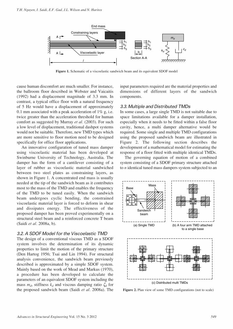
An innovative configuration of tuned mass damperusing viscoelastic material has been developed atSwinburne University of Technology, Australia. Thedamper has the form of a cantilever consisting of alayer of rubber as viscoelastic material sandwichedbetween two steel plates as constraining layers, asshown in Figure 1. A concentrated end mass is usuallyneeded at the tip of the sandwich beam as it contributesmost to the mass of the TMD and enables the frequencyof the TMD to be tuned easily. When the sandwichbeam undergoes cyclic bending, the constrainedviscoelastic material layer is forced to deform in shearand dissipates energy. The effectiveness of theproposed damper has been proved experimentally on astructural steel beam and a reinforced concrete T beam(Saidi et al. 2008a, b).
3.2. A SDOF Model for the Viscoelastic TMD
The design of a conventional viscous TMD as a SDOFsystem involves the determination of its dynamicproperties to limit the motion of the primary structure(Den Hartog 1956; Tsai and Lin 1994). For structuralanalysis convenience, the sandwich beam previouslydescribed is approximated by a simple SDOF system.Mainly based on the work of Mead and Markus (1970),a procedure has been developed to calculate theparameters of an equivalent SDOF system including themass md, stiffness kd and viscous damping ratio ζd forthe proposed sandwich beam (Saidi et al. 2008a). The
input parameters required are the material properties anddimensions of different layers of the sandwichcomponents.
3.3. Multiple and Distributed TMDs
In some cases, a large single TMD is not suitable due tospace limitations available for a damper installation,especially when it needs to be fitted within a false floorcavity, hence, a multi damper alternative would berequired. Some single and multiple TMD configurationsusing the proposed sandwich beam are illustrated inFigure 2. The following section describes thedevelopment of a mathematical model for estimating theresponse of a floor fitted with multiple identical TMDs.
The governing equation of motion of a combinedsystem consisting of a SDOF primary structure attachedto n identical tuned mass dampers system subjected to an
Advances in Structural Engineering Vol. 15 No. 3 2012 549
T.H. Nguyen, I. Saidi, E.F. Gad, J.L. Wilson and N. Haritos
Constraining layers
End mass
A
A Viscoelastic layer
h1h2h3
h1h2h3
Section A-Al
b kd
md
cd
Figure 1. Schematic of a viscoelastic sandwich beam and its equivalent SDOF model
(a) Single TMD (b) A four arm TMD attached to a single base
(c) Distributed multi TMDs
Sandwichbeam
BaseMass
Figure 2. Plan view of some TMD configurations (not to scale)

external harmonic force [Figure 3(a)] can be expressedby Eqn 1 (Yamaguchi and Harnpornchai 1993):
(1)
in which the mass matrix M, stiffness matrix K,damping matrix C, displacement vector x and forcingvector f are expressed as follows:
(3)
In these expressions m, k, c, x are the mass, stiffness,damping coefficient and displacement with subscripts sand d referring to the primary structure and the TMD,respectively. The external harmonic force has the formof F = F0ejωt in which ω is the forcing circular frequencyand j = √-1.
x f= { } =x x x x Fs d d dn... ..T
1 2 0 0 .. T0{ }
(2)
M =
m ...
ms
d
0 0 0
0 0 ...
m ...
... . .d
0
0 0 0
.. ... ... . ..
..0 0 0 .. m
k nk k
d
s d d
=
+
K
− − kk ... k
k k ...d d
d d
−− 0
k k ...
.d d
0
0 0−... ... ... ... ...
−− k ... kd d0 0
=
+
C
c nc c c ... cs d d d d− − −−−−
c c ...
cd d
d
0 0
c ...
... ..d0 0
.. ... ... ...
cd− 0 ... cd0
Mx Cx Kx f&& &+ + =
To simplify the form of the mathematical modeldeveloped in this section, the following conventionalterms are used:
(4)
where ωs and ωd and are the natural circular frequencies,ζs and ζd are the damping ratios of the primary systemand each TMD, respectively. Furthermore, thefollowing non-dimensional matrices M*, K*, C* areintroduced:
(5)
M* =
1 0 0 0
0 0
...
...µ
...
... ... ... .
0
0 0 0µ... ...
...0 0 0 µ
=
+
K*
1 2 2 2 2n f f f ... fµ µ µ µ− − −
− µµ µ
µ
f f ...
f
2 2
2
0 0
− f ...
... ...
0 02µ... ... ...
f− µ 2 0 ... f0 2µ
=C*
ζζ µ ζ µ ζ µ ζ µ ζµ ζ
s d d d d
d
n f f f ... f
f
+ − − −− f ...
fd
d
µ ζµ ζ
0 0
− f ...
...d0 0µ ζ
... ... ... ...
f ... fd− µ ζ µ0 0 ζζd
ω ω ζω
ζω
µ ω
ss
sd
d
ds
s
s s
dd
d d
d
s
k
m
k
m
c
m
c
m
m
mf
= = =
= = =
2
2dd
s sr
ωωω
=
550 Advances in Structural Engineering Vol. 15 No. 3 2012
Performance of Distributed Multiple Viscoelastic Tuned Mass Dampers for Floor Vibration Applications
Primarystructure
Primarystructure
EquivalentTMDn TMDs
F(t )F(t )
kd
Σkd
md
Σmd
xd
xdnxd1 xd 2
cd
Σcdkd
md
cd
ks ks
ms ms
xs xs
cs cs
kd
md
cd
Figure 3. A SDOF primary structure combined with MTMDs

which relate to the matrices M, K and C, respectively, as:
(6)
The general formulae to calculate the naturalfrequencies and steady state response of the combinedsystem will now be developed. The natural frequenciesωc of the combined system can be found by solving thefollowing equation:
(7)
which can be manipulated into a non-dimensional formof Eqn 8 by using the relationships stated in Eqn 6 andletting α* be the ratio of the frequency of the combinedsystem to that of the primary structure, i.e. α* = ωc /ωs.
(8)
The eigenvalue problem of Eqn 8 can be solved forα*, using Mathematica software (Wolfram 2008). The(n + 1)natural frequencies, from ω1 to ωn +1, of thecombined system in relation to that of the primarysystem, ωs, can be expressed as:
(9)
where the resultant α*1, 2 for a combined 2DOF system
with one TMD are given by Eqn 10 :
(10)
For a combined (n + 1)DOF system with n TMDs,the resultant parameters α*
1, 2, …, n + 1 are represented byEqn 11:
The steady-state solution for Eqn 1 can be calculatedby using exponential representation. Let the steady-statesolution of x be of the form:
(11)
α µ µ
α
12 2 2 21
21 1 1 1 4* = + +( ) − + +( ) −
n f n f f
22 3
121
21 1 1 1
* * *
*
....= = = =
= + +( ) + + ++
α α
α µ µ
n
n
f
n f n(( ) −
f f2 2 24
α µ µ1 22 2 2 21
21 1 1 1 4,
* = + +( ) + +( ) −
f f fm
ω α ω1 2 1 1 2 1, , ..., , , ...,*
n n s+ +=
det * * *K M−( ) =α 2 0
det K M−( ) =ωc2 0
M M K K K
C C C
* * *
* *
= = =
= =
m k m
c m
s s s s
s s s s
ω
ζ ω
2
2/
(12)
where X = {Xs Xd1 Xd2 ... Xdn}T is the vectorof displacement amplitude for the combinedsystem. Introducing a non-dimensional unit forcevector f* = {1 0 0 ... 0}T and substituting M*, C*, K*,X, f* into Eqn 1 yields:
(13)
Dividing Eqn 13 by the nonzero scalar e jωt and thenby the primary structure’s stiffness ks = msω 2
s yields acomplex matrix equation in terms of displacementvector X:
(14)
Solving Eqn 14 for the first root Xs, usingMathematica (Wolfram 2008), results in:
By manipulation, Eqn 15 can be simplified into:
(16)
where:
The dynamic magnification factors for steady statedisplacement response, Dd, and acceleration response,Da, of the primary structure in the combined system aredefined as:
(18)DX
F kD
X
F mr Dd
s
sa
s
sd= = =
0 0
2
/ /
&&
(17)
A f r
B rf
A r r f r n
d
12 2
1
22 4 2 2
2
1 1 4
= −=
= − + +( ) − +
ζ
µ rr f
B r r f f r n r
s d
s d
2
22 2 2 22 1
ζ ζ
ζ ζ µ= −( ) + + −( )
X
F k
A jB
A jBs
s0
1 1
2 2/=
− +( )+
(15)
X
F k
f r rf j
r r f r n
s
s
d
0
2 2
2 4 2 2
2
1 1
/
=− −( ) − ( )
− + +( ) −
ζ
µ(( )+ −( ) + − + −( )( )2 1 22 2 2 2jr r f f r n r r js d sζ ζ µ ζ
− + +( ) = ( )r jr F ks2
02M C K X f* * * */
− + +( ) =m j m k e F es s s sj t j tω ω ω ω ω2
02M C K X f* * * *
x X x X x X= = = −e j e ej t j t j tω ω ωω ω& && 2
Advances in Structural Engineering Vol. 15 No. 3 2012 551
T.H. Nguyen, I. Saidi, E.F. Gad, J.L. Wilson and N. Haritos

in which |Xs| is the magnitude (modulus) of the complexamplitude Xs. From Eqns 16 and 18, the dynamicmagnification factors for steady-state response of theprimary structure in the combined system can becomputed as:
Substituting n = 1 in Eqn 17, we can transform theformula for Dd in Eqn 19 to the one reported in Tsai andLin (1994) for a system with a single TMD. Therefore,the response of a primary structure attached to nidentical TMDs would be similar to the case when it isconnected to an equivalent single TMD (Figure 3). Theequivalent single TMD would have the same naturalfrequency and damping ratio as those of the multipleTMDs, with an equivalent mass being equals to the totalmass, nmd, of the multiple TMDs. This conclusion issignificant as we can apply exactly the optimumparameters developed for a single TMD to a system ofmultiple identical TMDs.
The formulae derived above can be used when alldampers are supported by a single base which isattached to the floor at the antinode of the controlledmode shape as in Figure 2(b). If dampers are distributedin some closely-spaced base locations as in Figure 2(c)
(19)DA B
A BD r
A B
A Bd a=
++
=++
12
12
22
22
2 12
12
22
22
then the modal displacement values associated with thebase locations should be taken into account whencalculating the mass of the equivalent single TMD. Thiscan be roughly described by Eqn 20:
(20)
where Md is the mass of the equivalent single TMD andui is the normalised modal displacement value at the baselocation to which a damper with mass mdi is attached.
4. DEVELOPMENT OF A VISCOELASTICDAMPER SYSTEM FOR AN OFFICEFLOOR
4.1. Description of the Problem Floor
Disturbing floor vibrations due to normal walkingtraffic were reported from the tenants occupying anoffice floor at a multi-story building located inMelbourne CBD, Australia. The most annoying areawas located at the north-west corner of the building withfloor beam spans of up to about 12.7 m as shown inFigure 4. This floor bay has two long corridors whichare perpendicular to each other. The walking paths arethus long enough for the vibration energy to build upand a walking induced steady state vibration to occur.Moreover, the distance from the intersection of thesecorridors to the closest work station is just about 1 m,which is too small to avoid the vibration effects.
M m ud di i= ∑ 2
552 Advances in Structural Engineering Vol. 15 No. 3 2012
Performance of Distributed Multiple Viscoelastic Tuned Mass Dampers for Floor Vibration Applications
RC WALLS
Problem floor bayWalking pathsColumns
G2
A
N
G3
B1
B1
G1
Figure 4. Floor plan and fit-out
4.2. Preliminary Determination of the Dynamic
Characteristics and Response Level of the
Floor
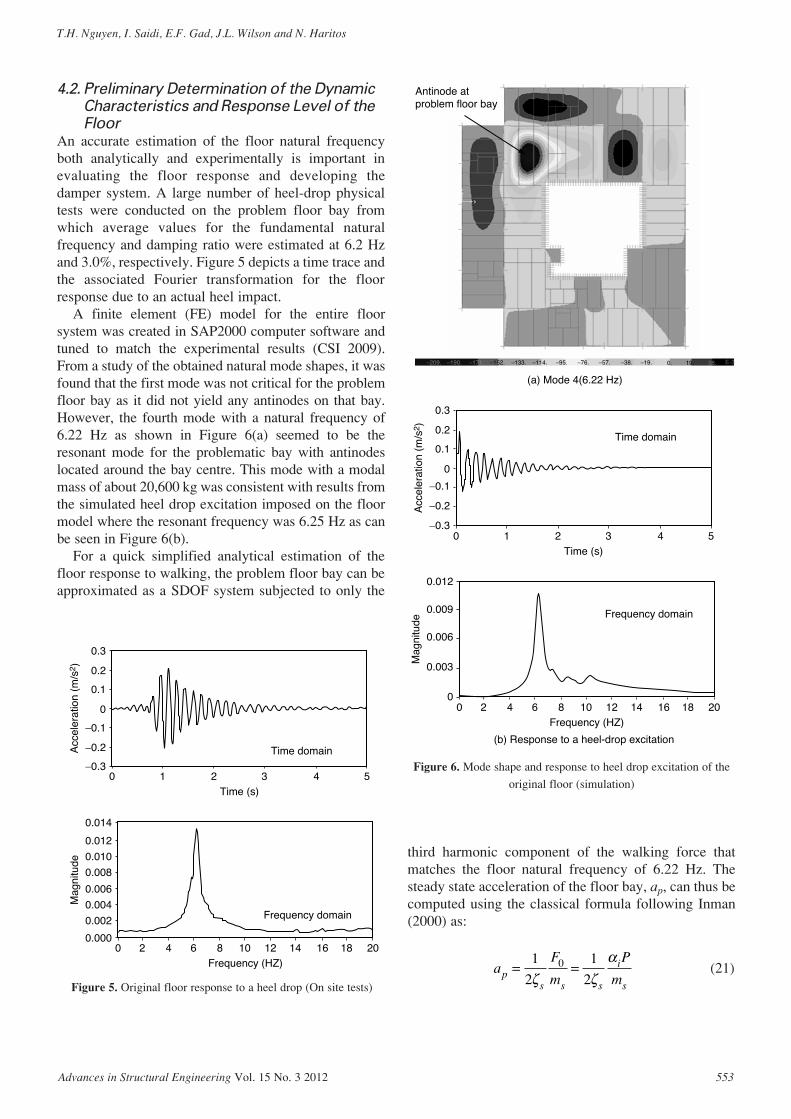
An accurate estimation of the floor natural frequencyboth analytically and experimentally is important inevaluating the floor response and developing thedamper system. A large number of heel-drop physicaltests were conducted on the problem floor bay fromwhich average values for the fundamental naturalfrequency and damping ratio were estimated at 6.2 Hzand 3.0%, respectively. Figure 5 depicts a time trace andthe associated Fourier transformation for the floorresponse due to an actual heel impact.
A finite element (FE) model for the entire floorsystem was created in SAP2000 computer software andtuned to match the experimental results (CSI 2009).From a study of the obtained natural mode shapes, it wasfound that the first mode was not critical for the problemfloor bay as it did not yield any antinodes on that bay.However, the fourth mode with a natural frequency of6.22 Hz as shown in Figure 6(a) seemed to be theresonant mode for the problematic bay with antinodeslocated around the bay centre. This mode with a modalmass of about 20,600 kg was consistent with results fromthe simulated heel drop excitation imposed on the floormodel where the resonant frequency was 6.25 Hz as canbe seen in Figure 6(b).
For a quick simplified analytical estimation of thefloor response to walking, the problem floor bay can beapproximated as a SDOF system subjected to only the
third harmonic component of the walking force thatmatches the floor natural frequency of 6.22 Hz. Thesteady state acceleration of the floor bay, ap, can thus becomputed using the classical formula following Inman(2000) as:
(21)aF
m
P
mps s s
i
s
= =1
2
1
20
ζ ζα
Advances in Structural Engineering Vol. 15 No. 3 2012 553
T.H. Nguyen, I. Saidi, E.F. Gad, J.L. Wilson and N. Haritos
Time domain
Time (s)0
0
0.1
0.2
0.3
−0.3
−0.2
−0.1
Acc
eler
atio
n (m
/s2 )
1 2 3 4 5
Frequency domain
Frequency (HZ)0
0.008
0.010
0.012
0.014
0.000
0.002
0.004
0.006
Mag
nitu
de
42 6 10 14 188 12 16 20
Figure 5. Original floor response to a heel drop (On site tests)
(a) Mode 4(6.22 Hz)
−209. −190. −171. −152. −133. −114. −95. −76. −57. −38. −19. 0. 19.
Antinode atproblem floor bay
(b) Response to a heel-drop excitation
38. E-3
Time domain
Time (s)0
0
0.1
0.2
0.3
−0.3
−0.2
−0.1
Acc
eler
atio
n (m
/s2 )
1 2 3 4 5
Frequency domain
Frequency (HZ)0
0.009
0.012
0
0.003
0.006
Mag
nitu
de
42 6 10 14 188 12 16 20
Figure 6. Mode shape and response to heel drop excitation of the
original floor (simulation)
in which the external forcing magnitude F0 is themultiplication of the Fourier coefficient αi taken as0.1 for the third harmonic (Murray et al. 2003) andthe walker’s weight P. The substitution of αi = 0.1,P = 800 N, ζs = 3.0% and ms = 20,600 kg into Eqn21 yields ap = 0.065 m/s2 or ap = 0.66% g.
Several one-spot walking tests were also carried outin which a person stood near the bay centre andwalked at the same location. Some practice wasneeded before there was a quite good match betweenthe step frequency and one-third of the floor naturalfrequency, so that the maximum floor response couldbe reached through resonance at the third harmonic.Peak acceleration measured from this type of test wasabout 0.75%–0.85% g. A typical time trace andFourier transformation for the measured floorresponse is shown in Figure 7 where it is observed thatthe greatest magnitude of the Fourier transformationoccurs at a frequency of 6.2 Hz, the natural frequencyof the floor bay.
Results from both the analytical and experimentalstudies discussed above revealed that floor peakresponse could exceed the threshold of 0.5% g for humancomfort in an office environment. This acceptable limitrecommended by Murray et al. (2003) tends to be a defacto standard for floor vibration assessment in NorthAmerica, Australia and other countries.
4.3. The Design and Manufacture of a
Viscoelastic Damper System
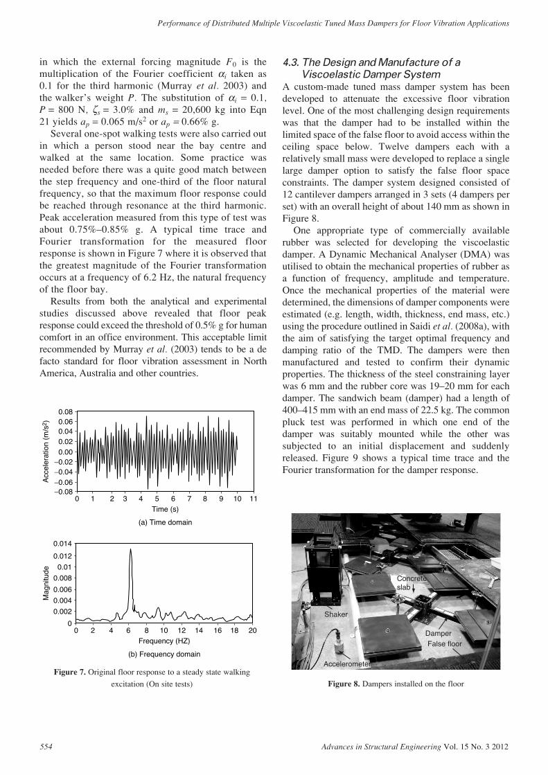
A custom-made tuned mass damper system has beendeveloped to attenuate the excessive floor vibrationlevel. One of the most challenging design requirementswas that the damper had to be installed within thelimited space of the false floor to avoid access within theceiling space below. Twelve dampers each with arelatively small mass were developed to replace a singlelarge damper option to satisfy the false floor spaceconstraints. The damper system designed consisted of12 cantilever dampers arranged in 3 sets (4 dampers perset) with an overall height of about 140 mm as shown inFigure 8.
One appropriate type of commercially availablerubber was selected for developing the viscoelasticdamper. A Dynamic Mechanical Analyser (DMA) wasutilised to obtain the mechanical properties of rubber asa function of frequency, amplitude and temperature.Once the mechanical properties of the material weredetermined, the dimensions of damper components wereestimated (e.g. length, width, thickness, end mass, etc.)using the procedure outlined in Saidi et al. (2008a), withthe aim of satisfying the target optimal frequency anddamping ratio of the TMD. The dampers were thenmanufactured and tested to confirm their dynamicproperties. The thickness of the steel constraining layerwas 6 mm and the rubber core was 19–20 mm for eachdamper. The sandwich beam (damper) had a length of400–415 mm with an end mass of 22.5 kg. The commonpluck test was performed in which one end of thedamper was suitably mounted while the other wassubjected to an initial displacement and suddenlyreleased. Figure 9 shows a typical time trace and theFourier transformation for the damper response.
554 Advances in Structural Engineering Vol. 15 No. 3 2012
Performance of Distributed Multiple Viscoelastic Tuned Mass Dampers for Floor Vibration Applications
(a) Time domain
Time (s)0
0.020.00
0.040.060.08
−0.08
−0.04−0.06
−0.02
Acc
eler
atio
n (m
/s2 )
21 3 54 6 7 8 9 10 11
(b) Frequency domain
Frequency (HZ)0
0.008
0.01
0.012
0.014
0
0.002
0.004
0.006
Mag
nitu
de
42 6 10 14 188 12 16 20
Figure 7. Original floor response to a steady state walking
excitation (On site tests)
Shaker
Accelerometer
False floorDamper
Concreteslab
Figure 8. Dampers installed on the floor

Due to construction tolerances in the dampers’dimension, minor variations in results from differentdampers could be expected. Test results revealed anestimated natural frequency of approximately 6.2 Hzand equivalent viscous damping ratio of about 5% forthe dampers. Whilst the damper could be tuned to thefloor natural frequency, it could not be designed withthe optimum damping ratio of about 6.7%, usingformulae suggested by Den Hartog (1956), due to therestriction in the properties of the available rubber.
4.4. Preliminary Estimation of the Retrofitted
Floor Response
A simplified estimation of the response of the floorwith dampers can be made by adopting the equivalentsingle damper concept outlined in Section 3.3. Astwelve dampers with a total mass of 276 kg aresupported by three bases which are 1.2 m apart, thecomputed effective mass for their equivalent singledamper using Eqn 20 is approximately 250 kg, takinginto account the departure of the bases from theantinode of the floor’s fundamental mode shape. Thetotal mass ratio, ∑µ, is thus about 1.2% for the wholedamper system. Using the procedure presented inSection 3.3, the maximum dynamic magnificationfactor for steady state acceleration response Da of thefloor fitted with dampers was calculated assuming anatural frequency of 6.2 Hz and a damping ratio of 5%for the dampers. From the computed Da of 8.4, thepeak acceleration for the floor fitted with dampers canbe estimated at 0.33% g, which is well within theacceptable range for human comfort. A reduction of50% in peak response is thus expected due to theaddition of dampers to the floor. However, if the floornatural frequency decreased to 6.0 Hz then a lowerresponse reduction of 40% would be expected. In bothcases, peak response of the floor retrofitted withTMDs would be below 0.5% g and within theacceptable range.
5. ANALYTICAL STUDY OF THE DAMPERSYSTEM PERFORMANCE
5.1. Floor FE Model Subjected to Walking
Excitations
Intensive investigations on the walking induced floorvibration were conducted via FE analysis. An equivalentconcentrated time-dependent walking force, F(t), wasapplied at the floor bay centre which is the antinode ofthe significant mode shape. The response of theproblematic floor bay was also collected from thislocation.
The Fourier series in Eqn 22 can be used to representthe walking force, F(t)
(22)
where fp is the step frequency in Hz and the averageweight of the walker P is assumed to be 800 N. Thedynamic coefficients for the first three harmoniccomponents of the walking excitation can be taken asα1 = 0.5, α2 = 0.2 and α3 = 0.1 (Murray et al. 2003). Thephase lag angles as proposed by Bachmann andAmmann (1987) are φ1 = 0, φ2 = φ3 = π/2.
The static weight can be subtracted from Eqn 22 sothat only the dynamic variation in forces is used foranalysis. Moreover, floor modal displacement alongthe walking path (floor span) with a length of L isassumed to follow the mode shape configuration of asimply supported beam in the form of a half-sinefunction as shown in Figure 10(a). This half-sinefunction can be added to the forcing function to allow for the moving characteristic of the walkingforce (Heinemeyer et al. 2009). If the walking speedvp is assumed to be constant along the path then thecoordinate z in Figure 10(a) can be replaced by vpt.These result in the simulated walking force of theform
F t P if ti p i( ) cos= + +( )
∑1 2α π φ
Advances in Structural Engineering Vol. 15 No. 3 2012 555
T.H. Nguyen, I. Saidi, E.F. Gad, J.L. Wilson and N. Haritos
Time (s)0
0
0.3
0.6
0.9
−0.9
−0.6
−0.3
Acc
eler
atio
n (m
/s2 )
1 2 3 4 5Frequency (HZ)
0
0.04
0.05
0.06
0
0.01
0.02
0.03
Mag
nitu
de
42 6 10 14 18 208 12 16 22
Figure 9. Damper response to a pluck test

(23)
From the relationship between the walking speed, vp,and step frequency, fp, given in tabulated form inBachmann & Ammann (1987), we can derive a curve-fitfunction for this as
(24)
so that vp in Eqn 23 can now be replaced by Eqn 24 interms of fp. A typical time trace for the walking force ofEqn 23 is illustrated in Figure 10(b).
A range of common step frequencies should be usedto take into account the variation in walking speed thatthe floor would experience. Therefore, fifty-five timetraces for walking force in the form of Eqn 23 wereproduced with step frequencies varying from 1.85 to2.3 Hz as the input for the FE simulation, which would
v f fp p p= − +1 6667 4 8333 4 52. . .
F t P if tv
Lti p i
p( ) cos sin= +( )
∑α π φ
π2
cover the range of normal and fast walking activities.The fine frequency resolution of the input loadingspectrum ensures a close match between the forcingfrequency and the natural frequencies of the floor withand without dampers.
FE models developed for the original floor and thefloor with dampers were analysed, using SAP2000computer software (CSI 2009) and each model wassubjected to 55 time traces of walking force. A typicalplot of floor acceleration response in time domain isshown in Figure 11(a), for both the original floor andthe floor fitted with dampers having frequency of6.2 Hz, assuming a damping ratio of 3% and 5% for thefloor and the added dampers, respectively. This plotdescribes the case when the floor is excited atresonance, i.e. the third harmonic 3fp coincides with thefloor frequency (about 6.2 and 5.8 Hz for the floorwithout and with dampers, respectively). It can be seenthat the bare floor would experience a maximumacceleration of up to 0.73% g which exceeds theacceptable limit of 0.5% g while the installation of the
556 Advances in Structural Engineering Vol. 15 No. 3 2012
Performance of Distributed Multiple Viscoelastic Tuned Mass Dampers for Floor Vibration Applications
z
z
L
1
F(t )
u(z) = sin Lπz
(a) Simiplified mode shape
Time (s)0
0
200
400
600
−400
−200
For
ce (
N)
2 4 6 8 10
(b) Time history for walking force
Figure 10. Modeling of walking excitation
Time (s)0
0
0.02
0.06
0.04
0.08
−0.08
−0.04
−0.06
−0.02
Acc
eler
atio
n (m
/s2 )
2 4 6 8 10
Without TMDsWith TMDs
Step frequency (Hz)1.8
0.4%
0.6%
0.8%
1.0%
0.0%
0.2%
Flo
or p
eak
acce
lera
tion
(g)
1.9 2.0 2.1 2.2 2.3
Without TMDsWith TMDs
(a) Floor response to walking at resonance (b) Floor response spectrum
Figure 11. Floor response to walking excitation (simulation)

6.2 Hz dampers can reduce the peak response to0.38% g. A floor response spectrum was then producedas shown in Figure 11(b), showing the expected peakresponse of the floor due to different step frequencyvalues. Each data point in Figure 11(b) was collectedfrom an appropriate time history analysis. For theoriginal floor, the response spectrum has one peak at astep frequency of one-third of the natural frequency of6.2 Hz. This peak is split into two lower peaks in theresponse spectrum of the floor with dampers, being atstep frequencies of one-third of the natural frequenciesof 5.8 and 6.6 Hz. It is demonstrated that vibrationlevels of the damper-fitted floor are within theacceptable threshold for all the normal and fast walkingrates.
5.2. Sensitivity Analysis
5.2.1. Floor frequency variation
The effect of variations in the dynamic characteristics ofthe floor on the vibration control efficiency wasinvestigated. The floor natural frequencies coulddecrease or increase in accordance with an increase ordecrease in floor mass associated with the live load.Design guidelines usually recommend a value of 10% to20% of the nominal live load being considered ascontribution to the floor mass when performingdynamic analysis (Murray et al. 2003; Sedlacek et al.2006; Hechler et al. 2008). Using FE modal analysis,the resonant frequency of the floor bay may vary within6.0 and 6.4 Hz due to such a change in the effectivefloor live load. The effective live load, which is the mostlikely variable component, seems to contribute least tothe total mass of this fully furnished concrete floor. Fouradditional FE models were then analysed under walkingexcitations to account for the possible variation in liveload. These included two models without dampers inwhich the floor bay frequencies were 6.0 and 6.4 Hz,and the corresponding two models with dampers
installed and tuned to 6.2 Hz. From the time historyanalysis results, floor response spectra were created ascan be seen in Figure 12, comparing peak accelerationsof the floor with and without dampers when subjected todifferent footfall rates.
Without dampers, the peak acceleration atresonance was 0.74% g and 0.72% g for the floors withnatural frequency of 6.0 and 6.4 Hz, respectively,compared with 0.73% g for the floor with a naturalfrequency of 6.2 Hz. It is hence reasonable from thesecases that a minor decrease or increase in mass resultedin a minor increase or decrease in the response level.With dampers installed and tuned to 6.2 Hz, the floorcan reach a maximum acceleration of 0.43% g and0.38% g, which translate to a response reduction of42% and 48%, for the original floor naturalfrequencies of 6.0 and 6.4 Hz, respectively. It seemsthat a TMD is more effective when its tuned frequency(6.2 Hz) is lower than that of the floor (6.4 Hz).However, in all investigated situations the maximumresponse of the damper-retrofitted floor is well belowthe recommended threshold of 0.5% g for humancomfort.
5.2.2. Floor and damper frequencies variation
Further investigations have been conducted, allowingfor a likely variation in natural frequencies of both thefloor and damper. The floor, which was assumed tohave a natural frequency of 6.0 or 6.4 Hz, was thenfitted with dampers with frequencies of 6.4 or 6.0 Hz.Floor response spectra were created as can be seen inFigure 13 in which each point of the plot was obtainedfrom an appropriate time history analysis case. Withdampers, the floor reached a maximum acceleration of0.41% g or 0.51% g which corresponds to a responsereduction of 43% and 32%, depending on whether theTMD frequency is lower or greater than the floorfrequency.
Advances in Structural Engineering Vol. 15 No. 3 2012 557
T.H. Nguyen, I. Saidi, E.F. Gad, J.L. Wilson and N. Haritos
Step frequency (Hz)1.8
0.4%
0.6%
0.8%
1.0%
0.0%
0.2%
Flo
or p
eak
acce
lera
tion
(g)
1.9 2.0 2.1 2.2 2.3 2.4
Bare floor 6.0 HzFitted floor with dampers 6.2 Hz
Step frequency (Hz)1.8
0.4%
0.6%
0.8%
1.0%
0.0%
0.2%
Flo
or p
eak
acce
lera
tion
(g)
1.9 2.0 2.1 2.2 2.3 2.4
Bare floor 6.4 HzFitted floor with dampers 6.2 Hz
Figure 12. Effects of variations in floor frequency

5.2.3. Floor damping variation
Finally, uncertainty in the estimation of the floordamping was considered. Response levels of the floorwith and without dampers were estimated again butwith an inherent damping ratio of 2.5% for theoriginal (bare) floor, i.e. lower than the 3% usedpreviously. Typical results for comparison are shownin Figure 14 in which the natural frequency of thefloor and damper was assumed to be 6.2 Hz. Withoutdampers, the peak acceleration of the floor increasedfrom 0.73% g to 0.84% g as the floor dampingdecreased from 3% to 2.5%. In contrast, with thedampers fitted, a peak acceleration of 0.41% g wasobtained for the floor with a damping ratio of 2.5%,compared with 0.38% g of the 3% damping case. Aresponse reduction of about 51% was thus obtaineddue to the installation of the damper to a floor with anoriginal damping ratio of 2.5% and as expected, theeffectiveness of a TMD system is higher for a floorwith a lower damping ratio.
6. EXPERIMENTAL STUDY OF THE DAMPERSYSTEM PERFORMANCE
Field vibration measurements have been taken with thecase study floor being subjected to various types ofexcitation, including heel drop, walking along thecorridor and forced vibration using an electrodynamicshaker.
A large number of walking-induced vibration testshave been undertaken in which the walking speed andstep length were adjusted in an attempt to closelymatch the third harmonic of the step frequency withthe floor natural frequency to reach the maximumfloor response. Measurements taken before theinstallation of the dampers revealed a peakacceleration floor response of about 0.67% of gravity,which exceeds the recommended level for humancomfort of 0.5% of gravity. After the dampers hadbeen installed, the maximum acceleration level fromall walking tests was found to decrease to around0.3%–0.4% g, which is well within the acceptablerange. It was also been observed that the floor felt lesslively after fitting of the dampers in both standing andsitting positions. Samples of the peak floor responseto walking are shown in Figure 15 whilst typical timetraces for the walking induced response are illustratedin Figure 16.
A series of tests were also conducted using anexternal electrodynamic shaker which excited the floorwith a defined dynamic force and frequency range. Asignal generator and power amplifier were utilised toensure the same loading was input onto the originalfloor and the floor fitted with dampers. After severaltrials, a swept sine excitation with a frequencybandwidth of 5–7 Hz was selected, covering theresonant frequencies of the floor with and withoutdampers. This adopted frequency range also covered
558 Advances in Structural Engineering Vol. 15 No. 3 2012
Performance of Distributed Multiple Viscoelastic Tuned Mass Dampers for Floor Vibration Applications
Step frequency (Hz)1.8
0.4%
0.6%
0.8%
1.0%
0.0%
0.2%
Flo
or p
eak
acce
lera
tion
(g)
1.9 2.0 2.1 2.2 2.3 2.4
Bare floor 6.4 HzFitted floor with dampers 6.0 Hz
Step frequency (Hz)1.8
0.4%
0.6%
0.8%
1.0%
0.0%
0.2%
Flo
or p
eak
acce
lera
tion
(g)
1.9 2.0 2.1 2.2 2.3 2.4
Bare floor 6.0 HzFitted floor with dampers 6.4 Hz
Figure 13. Effects of variations in floor frequency and dampers frequency
1.0%
0.8%
0.6%
0.4%
0.2%
0.0%1.8 1.9
Fitted floor, ζs = 3.0%
Bare floor, ζs = 3.0%
Fitted floor, ζs = 2.5%
Bare floor, ζs = 2.5%
2.0Step freqency (Hz)
Flo
or p
eak
acce
lera
tion
(g)
2.1 2.2 2.3 2.4
Figure 14. Effects of floor damping

the likely forcing frequency of the third harmonic of awalking excitation at normal and fast speed that thefloor may experience. The response of the floor to thesame shaker loading was measured before and after theinstallation of the dampers with recorded time historiesas illustrated in Figure 17. Peak values obtained fromacceleration time traces were collected and plotted inFigure 19 for different tests. Figure 18 depicts theFourier transformation for the floor response before
and after the dampers installation. From this figure, thedampers can be seen to lower and flatten the sharppeak response at the floor fundamental frequency.Generally, there was a reduction of 40% in peak floorresponse to the shaker excitation, from 1.59% g for theoriginal floor (Figure 19(a)) to 0.96% g for the floorwith dampers (Figure 19(b)). In other words, theresulting response of the floor with the dampers was60% of the original vibration levels.
Advances in Structural Engineering Vol. 15 No. 3 2012 559
T.H. Nguyen, I. Saidi, E.F. Gad, J.L. Wilson and N. Haritos
Test number
0.3%
0.4%
0.6%
0.5%
0.7%
0.0%
0.1%
0.2%
Pea
k ac
cele
ratio
n (g
)
1 2 3 4
Threshold = 0.5% g
5 6 87
(a) Without TMDs
Test number
0.3%
0.4%
0.6%
0.5%
0.7%
0.0%
0.1%
0.2%
Pea
k ac
cele
ratio
n (g
)
1 2 3 4
Threshold = 0.5% g
5 6 87
(b) With TMDs
Figure 15. Floor peak response to walking excitation (On site tests)
Time (s)
0
0.025
0.05
0.075
−0.075
−0.05
−0.025
Acc
eler
atio
n (m
/s2 )
20 4 6 8 10
(a) Without TMDs
Time (s)
0
0.025
0.05
0.075
−0.075
−0.05
−0.025A
ccel
erat
ion
(m/s
2 )
20 4 6 8 10
(b) With TMDs
Figure 16. Floor response to walking excitation (On site tests)
Time (s)
0
0.05
0.1
0.15
0.2
−0.2
−0.15
−0.1
−0.05
Acc
eler
atio
n (m
/s2 )
100 20 30 40 50 60
(b) With TMDs
Time (s)
0
0.05
0.1
0.15
0.2
−0.2
−0.15
−0.1
−0.05
Acc
eler
atio
n (m
/s2 )
100 20 30 40 50 60
(a) Without TMDs
Figure 17. Floor response to shaker excitation (On site tests)

7. CONCLUSIONSA new viscoelastic damper has been specificallydeveloped for floor vibration applications and asimplified procedure proposed to model the sandwichbeam damper as an equivalent SDOF system.
Analytical models and procedures have beendeveloped to estimate the floor response when fittedwith the new dampers. The proposed procedure canpredict the effectiveness of the TMD system in single,multi and distributed configurations, with any rubberproperties. In the event that a single damper cannot beused because of any restrictions in fabrication orinstallation then several smaller dampers with the samefrequency and damping ratio could be used as describedin this paper.
The design of an innovative distributed multipleviscoelastic damper system for an existing office floorhas been presented. The damper system is compact andelegant and can be installed within the available space ofthe false floor, requiring no structural or architecturalmodifications to the floor. Intensive numerical studieswere performed, taking into account the effects ofdamper location and the variation in the floor and/ordampers dynamic characteristics. The analyticalinvestigations presented were in good agreement with
the experimental work conducted on a real floor. Theinstalled dampers successfully reduced the floorvibrations by at least 40% to a level that was well withinthe acceptable limit for human comfort in an officeenvironment.
REFERENCES
Allen, D. and Pernica, G. (1984). “A simple absorber for walking
vibrations”, Canadian Journal of Civil Engineering, Vol. 11,
No. 1, pp. 112–117.
Allen, D.L. and Swallow, J.C. (1975). “Annoying floor vibrations -
diagnosis and therapy”, Journal of Sound and Vibration, Vol. 9,
No. 3, pp. 12–17.
Bachmann, H. and Ammann, W. (1987). Vibrations in Structures:
Induced by Man and Machines, International Association for
Bridge and Structural Engineering (IABSE).
CSI (2009). SAP2000 - Static and Dynamic Finite Element Analysis
of Structures, 14th Edition, Computers and Structures, Inc.,
Berkeley, California, USA.
Den Hartog, J.P. (1956). Mechanical Vibrations, McGraw-Hill Book
Company, Inc., New York, USA.
Díaz, I. and Reynolds, P. (2009). “Acceleration feedback control
of human-induced floor vibrations”, Engineering Structures,
Vol. 32, No. 1, pp. 163–173.
560 Advances in Structural Engineering Vol. 15 No. 3 2012
Performance of Distributed Multiple Viscoelastic Tuned Mass Dampers for Floor Vibration Applications
Frequency (Hz)
0.0010
0.0015
0.0020
0.0000
0.0005
FF
T m
agni
tude
(g)
10 2 3 4 5 6 98 107
(a) Without TMDs
Frequency (Hz)
0.0010
0.0015
0.0020
0.0000
0.0005
FF
T m
agni
tude
(g)
10 2 3 4 5 6 98 107
(b) With TMDs
Figure 18. Floor response to shaker excitation, frequency domain (On site tests)
Test number
0.8%
1.2%
1.6%
2.0%
0.0%
0.4%
Pea
k ac
cele
ratio
n (g
)
1 2 3 4 5 6 87
(a) Without TMDs
Test number
1.2%
1.6%
2.0%
0.0%
0.4%
0.8%P
eak
acce
lera
tion
(g)
1 2 3 4 5 6 87
(b) With TMDs
Figure 19. Floor peak response to shaker excitation (On site tests)

Díaz, I. and Reynolds, P. (2010). “On-off nonlinear active control of
floor vibrations”, Mechanical Systems and Signal Processing,
Vol. 24, No. 6, pp. 1711–1726.
Hanagan, L. and Murray, T. (1997). “Active control approach for
reducing floor vibrations”, Journal of Structural Engineering,
ASCE, Vol. 123, No. 11, pp. 1497–1505.
Hechler, O., Feldmann, M., Heinemeyer, C. and Galanti, F. (2008).
“Design guide for floor vibrations”, Proceedings of EuroSteel
2008 Conference, Graz, Austria.
Heinemeyer, C., Butz, C., Keil, A., Schlaich, M., Goldack, A.,
Trometer, S., Lukic, M., Chabrolin, B., Lemaire, A., Martin, P.O.,
Cunha, Á. and Caetano, E. (2009). Design of Lightweight
Footbridges for Human Induced Vibrations, European
Commission.
Hewitt, C. and Murray, T. (2004). “Office fit-out and floor
vibrations”, Modern Steel Construction, April, pp. 35–38.
Inman, D. (2000). Engineering Vibrations, Prentice Hall Englewood
Cliffs, New Jersey, USA.
Lenzen, K.H. (1966). “Vibration of steel joist-concrete slab floors”,
Engineering Journal, Vol. 3, pp. 133–136.
Matsumoto, Y., Nishioka, T., Shiojiri, H. and Matsuzaki, K. (1978).
“Dynamic design of footbridges”, Proceedings of the
International Assocociation of Bridge Structural Engineering,
Vol. 2, pp. 1–15.
Mead, D.J. and Markus, S. (1970). “Loss factors and resonant
frequencies of encastré damped sandwich beams”, Journal of
Sound and Vibration, Vol. 12, No. 1, pp. 99–112.
Murray, T.M., Allen, D.E. and Ungar, E.E. (2003). Design Guide 11,
Floor Vibrations Due to Human Activities, 2nd Edition, American
Institute of Steel Construction (AISC) & Canadian Institute of
Steel Construction (CISC).
Saidi, I., Gad, E., Wilson, J. and Haritos, N. (2008a). “Innovative
passive viscoelastic tuned mass damper for floor vibration
applications”, Proceedings of Australian Earthquake
Engineering Society Conference, Ballarat, VIC, Australia.
Saidi, I., Mohammed, A.D., Gad, E.F., Wilson, J.L. and Haritos, N.
(2008b). “Development of viscoelastic tuned mass damper for
floor vibration applications”, Proceedings of Australian
Structural Engineering Conference (ASEC), Melbourne,
Australia.
Sedlacek, G., Heinemeyer, C., Butz, C., Volling, B., Waarts, P. and
Van, D. (2006). Generalisation of Criteria for Floor Vibrations
for Industrial, Office, Residential and Public Building and
Gymnastic Halls, Office for Official Publications of the European
Communities.
Setareh, M. and Hanson, R. (1992). “Tuned mass dampers for
balcony vibration control”, Journal of Structural Engineering,
ASCE, Vol. 118, No. 3, pp. 723–740.
Setareh, M., Ritchey, J., Baxter, A. and Murray, T. (2006). “Pendulum
tuned mass dampers for floor vibration control”, Journal of
Performance of Constructed Facilities, Vol. 20, No. 1, pp. 64–73.
Setareh, M., Ritchey, J., Murray, T., Koo, J. and Ahmadian, M.
(2007). “Semiactive tuned mass damper for floor vibration
control”, Journal of Structural Engineering, ASCE, Vol. 133,
No. 2, pp. 242–250.
Shope, R. and Murray, T. (1995). “Using tuned mass dampers to
eliminate annoying floor vibrations”, Proceedings of Structures
Congress XIII, ASCE, pp. 339–348.
Smith, A., Hicks, S. and Devine, P. (2009). Design of Floors for
Vibration: a New Approach (Revised Edition), The Steel
Construction Institute Publication, Ascot, UK.
Son, L., Kawachi, M., Matsuhisa, H. and Utsuno, H. (2007).
“Reducing floor impact vibration and sound using a momentum
exchange impact damper”, Journal of System Design and
Dynamics, Vol. 1, No. 1, pp. 14–26.
Son, L., Yamada, K., Hara, S., Utsuno, H. and Matsuhisa, H. (2008).
“Reduction of floor shock vibration by active momentum
exchange impact damper”, Journal of System Design and
Dynamics, Vol. 2, No. 4, pp. 930–939.
Tsai, H.C. and Lin, G.C. (1994). “Explicit formulae for optimum
absorber parameters for force-excited and viscously damped
systems”, Journal of Sound and Vibration, Vol. 176, No. 5,
pp. 585–596.
Webster, A. and Vaicaitis, R. (1992). “Application of tuned mass
dampers to control vibrations of composite-floor systems”,
Engineering Journal of the American Institute of Steel
Construction, Vol. 29, No. 3, pp. 116–124.
Willford, M. and Young, P. (2006). A Design Guide for Footfall
Induced Vibration of Structures, The Concrete Society
Publication CCIP-016, Trowbridge, UK.
Willford, M., Young, P. and Algaard, W. (2006). “A constrained
layer damping system for composite floors”, Structural Engineer,
Vol. 84, No. 4, pp. 31–38.
Wolfram (2008). Mathematica7 Software (Online help), Wolfram
Research, Champaign, IL, USA.
Yamaguchi, H. and Harnpornchai, N. (1993). “Fundamental
characteristics of multiple tuned mass dampers for suppressing
harmonically forced oscillations”, Earthquake Engineering &
Structural Dynamics, Vol. 22, No. 1, pp. 51–62.
NOTATIONM, K, C mass, stiffness and damping matricesx, x. , x.., f displacement, velocity, acceleration
and forcing vectorsF, F0, ω time-dependent force, its magnitude
and frequencyn the number of TMDsj = √-1 imaginary unitms, ks, cs, ζs modal mass, stiffness, damping
coefficient and damping ratio of thefloor
md, kd, cd, ζd modal mass, stiffness, damping co-efficient and damping ratio of theTMD
M*, K*, C*, f* non-dimensional matrices and vectorassociated with M, K, C and f
Advances in Structural Engineering Vol. 15 No. 3 2012 561
T.H. Nguyen, I. Saidi, E.F. Gad, J.L. Wilson and N. Haritos

µ, f, r mass ratio, damper frequency ratioand forcing frequency ratio
α*,ωc natural frequency ratio and naturalfrequency of the combined system(with TMDs)
|Xs|, |X..
s| magnitudes of displacement andacceleration steady-state response ofthe floor
A1, B1, A2, B2 notations to simplify the expressionfor the floor steady-state response
Dd, Da dynamic magnification factors for thefloor steady-state response
Md modal mass of the equivalent singleTMD
u normalised mode shape valueap steady-state acceleration at resonance
of the floor without damperP static weight of the walkerαi, φi dynamic coefficient and phase lag
angle for the i-th harmonic of walkingexcitation
vp, fp walking speed and step frequencyL length of walking path (floor span)g acceleration of gravity
562 Advances in Structural Engineering Vol. 15 No. 3 2012
Performance of Distributed Multiple Viscoelastic Tuned Mass Dampers for Floor Vibration Applications