performance of a conductive-paint anode … report performance of a conductive-paintanode in...
TRANSCRIPT

FINAL REPORT
PERFORMANCEOF A CONDUCTIVE-PAINT ANODE
IN CATHODIC PROTECTION SYSTEMSFOR INLAND CONCRETE BRIDGE PIERS
IN VIRGINIA
GERARDO G. CLEMEN-A, Ph.D.Principal Research Scientist
Virginia Transportation Research Council
DONALD It JACKSONSenior Program Manager
Office of Technology ApplicationsFederal Highway Administration
VIRGINIA TRANSPORTATION RESEARCH COUNCIL

Standard Title Page - Report on Federally Funded Project1. Report No.FHWANTRC 98-R7
2. Government Accession No. 3. Recipient's Catalog No.
4. Title and SubtitlePerformance of a Conductive-Paint Anode in Cathodic Protection Systemsfor Inland Concrete Bridge Piers in Virginia
7. Author(s)Gerardo G. Clemefia, Ph.D., and Donald R. Jackson
9. Performing Organization and Address
Virginia Transportation Research Council530 Edgemont RoadCharlottesville, VA 2290312. Sponsoring Agencies' Name and Address
5. Report DateSeptember 1997
6. Performing Organization Code
8. Performing Organization Report No.VTRC 98-R7
10. Work Unit No. (TRAIS)
11. Contract or Grant No.9617-010 and 9632-010
13. Type of Report and Period Covered
Virginia Department of Transportation1401 E. Broad StreetRichmond, VA 2321915. Supplementary Notes
FHWA1504 Santa Rosa RoadRichmond, VA 23239
14. Sponsoring Agency Code
16. AbstractAs part of efforts to identify effective and durable anodes for use in cathodic protection of different reinforced concrete members, awater-based conductive paint was tested in two CP systems that were built, one 8 years ago and the other 6 years ago, to protect theconcrete piers of twin inland bridges in Virginia. Measurements made at various times of circuit current, voltage, rebar potential,and 4-hour polarization indicated that the CP systems were providing more than sufficient protection to the rebars. Natural paintdeterioration (peeling, cracks, stains, etc.) that was observed in the conductive paint ranged from 0% to 0.37% in the older systemand 0% to 0.14% in the newer system. Most of the deterioration was located at the exposed ends of the pier caps. Overall, theperformance of the conductive paint indicated that (1) earlier prediction by some experts of premature failure of the paint once it ispolarized is unwarranted, and (2) barring any extremely rapid paint deterioration in the future, it is a reasonable estimate that theservice life of the conductive paint is at least 15 years - especially if minor paint deterioration is touched up as early as possible.
17 Key Wordsreinforced concrete, concrete piers, steel corrosion, cathodicprotection, anode, conductive paint.
18. Distribution StatementNo restrictions. This document is available to the public throughNTIS, Springfield, VA 22161.
19. Security Classif. (of this report)Unclassified
20. Security Classif. (of this page)Unclassified
21. No. of Pages34
22. Price
Form DOT F 1700.7 (8-72) Reproduction of completed page authorized

FINAL REPORT
PERFORMANCE OF A CONDUCTIVE-PAINT ANODE IN CATHODIC PROTECTIONSYSTEMS FOR INLAND CONCRETE BRIDGE PIERS IN VIRGINIA
Gerardo G. Clemeiia, Ph.D.Principal Research Scientist
Virginia Transportation Research Council
Donald R. JacksonSenior Program Manager
Office of Technology ApplicationsFederal Highway Administration
(The opinions, findings, and conclusions expressed in thisreport are those of the authors and not necessarily
those of the sponsoring agencies.)
Virginia Transportation Research Council(A Cooperative Organization Sponsored Jointly by the
Virginia Department of Transportation andthe University of Virginia)
In Cooperation with the U.S. Department of TransportationFederal Highway Administration
Charlottesville, Virginia
September 1997VTRC 98-R7

Copyright 1997, Virginia Department of Transportation.
ii

ABSTRACT
As part of efforts to identify effective and durable anodes for use in cathodic protection(CP) of reinforced concrete members, a water-based, electrically conductive paint was evaluatedfor use as the secondary anode in CP systems for protecting inland concrete piers. In such piers,the concrete areas susceptible to rebar corrosion are not constantly wet as they are in marineenvironments. The paint was used in two CP systems, one 6 years old and the other 8 years old,that were designed to protect the concrete piers of two pairs of twin bridges in inland Virginia.
Measurements of circuit current, circuit voltage, rebar potential, and 4-hourdepolarization indicated that the two CP systems were operating as expected and providing morethan sufficient protection to the rebars in the concrete piers. Paint deterioration, such as peeling,cracks, and stains, occurred in both systems. The extent of the deterioration was estimated withthe use of a newly developed digital image analysis method, and the largest area of damage was2.40 percent of the total coated concrete area of a pier protected by the older CP system. Sincethis unusually large area was restricted to the upstream-side footing of the pier, it was attributedto abrasion and damage caused by timber debris crashing against the footing as the result ofrecent severe flooding. Other than this area, the natural deterioration in the paint system rangedfrom only 0 to 0.37 percent. Similar deterioration in the second paint system ranged from only 0to 0.14 percent.
Most of the paint deterioration in both systems was at the ends of the pier caps, where theconcrete was not sheltered from rain by the deck overhang. This suggests that even with inlandconcrete piers, deterioration of the conductive paint, albeit slow, can occur on any portion of theconcrete that becomes wet intermittently, either by rainfall or drainage from the deck. Therefore,extra measures for avoiding this problem must be considered in the design of any CP system thatuses the conductive paint as a secondary anode.
Overall, the performance of the paint was better than expected, and its effectiveness canreasonably be expected to last for at least 15 years if minor deterioration is touched up as soon aspossible. This type of conductive paint can, therefore, be considered a suitable secondary anodefor use in CP of inland concrete piers.
iii

FINAL REPORT
PERFORMANCE OF A CONDUCTIVE-PAINT ANODE IN CATHODIC PROTECTIONSYSTEMS FOR INLAND CONCRETE BRIDGE PIERS IN VIRGINIA
Gerardo G. Clemefia, Ph.D.Principal Research Scientist
Virginia Transportation Research Council
Donald R. JacksonSenior Program Manager
Office of Technology ApplicationsFederal Highway Administration
INTRODUCTION
In the last few years, research related to mitigating the corrosion of steel reinforcement inconcrete structures has increased. Such mitigation has included cathodic protection (CP) andelectrochemical chloride extraction (ECE).1-3 There is increased recognition among academicsand practicing engineers in the United States and Europe that such electrochemical methods arethe only effective and practical solutions for mitigating this costly problem. The alternative is toreplace the contaminated concrete. As Uhlig and Revie stated in their widely used textbookCorrosion and Corrosion Control: "Cathodic protection is perhaps the most important of allapproaches to corrosion control. By means of an externally applied electric current, corrosion isreduced virtually to zero, and a metal surface can be maintained in a corrosive environmentwithout deterioration for an indefinite time.,,4
In simple terms, except for the galvanic mode of CP, ECE and the impressed-currentmode of CP are implemented by installing a supplemental anode system on the surface of theconcrete structure, followed by applying a DC current between the anode and the rebar network,with the latter serving as the cathode. The difference between these methods is their aims: ECEaims to remove as much chloride ion as possible within a reasonable time, and CP aims toachieve and maintain sufficient cathodic polarization of the reinforcing steel. Therefore, ECEtreatment of a concrete structure typically requires 4 to 8 weeks using a DC current ranging from1.1 to 5.5 Nm2 (100 to 500 mNft2
). The beneficial effects on the reinforcing steel can last forseveral years. Exactly how long is still being investigated. The latest results from regularmonitoring of a portion of a pier in Canada, treated 7 years ago, indicate the steel is still passive,which means that the beneficial effects likely last for at least 7 years (unpublished data). Incontrast, CP typically uses DC current on the order of 11 mNm2 (1 mNft2
) to cathodicallypolarize the reinforcing steel. As long as this current and the entire electrical system areoperating and being maintained properly, the structure will be permanently protected.

The selection of a suitable anode is critical to the durability and, therefore, theeffectiveness of any CP system. The search for good anodes for application in CP of concretebridge decks began at the Virginia Transportation Research Council (VTRC) in the early1980s.5
-7 Since the requirements for a good anode for inland concrete piers are different from
those for concrete decks and piers in marine environments, the search for good anodes for use oninland concrete piers began as early as the mid-1980s.
For CP of inland concrete piers, an anode should have at least the followingcharacteristics: electrically conductive, ability to sustain oxidation without significant physicaldamage, inexpensive, easy and safe to install or apply, and reasonably easy to maintain. The firsteffort in this search was a small-scale trial, sponsored by the Federal Highway Administration(FHWA), that involved the use of a sprayable conductive polymer coating and a metallized zinccoating, separately, as secondary anodes on two concrete piers of the eastbound bridge of 1-64over 13th View Street in Norfolk, Virginia.8 Even though the bridge is on the Atlantic coast ofVirginia, the piers were considered inland, because they are on the ground and not surrounded byseawater. The primary anode was platinized niobium copper (Pt-Nb-Cu) wires. The conductivepolymer coating appeared to perform satisfactorily for a few years. However, concerns with thepotential adverse effects of the organic solvents used in its formulation on construction workersand its long-term appearance made this system unfavorable to potential users. The metallizedzinc coating had desirable characteristics. However, it can easily create electrical shorts with tiewires that often extend from just beneath the concrete surface, especially at the underside of piercaps. In addition, because of the chemical properties of zinc, its long-term durability is inquestion. Lately, health and environmental concerns with zinc, especially in the vapor phase,have warranted the use of containment around construction areas such that the cost has risenconsiderably.
In 1988, when the 93 hammer-head concrete piers supporting the 1-95 bridges over theJames River in Richmond, Virginia, needed major rehabilitation, the Virginia Department ofTransportation (VDOT) chose to apply CP on at least the pier caps, which would necessitate thatonly damaged concrete be excavated and replaced. The other option would have necessitatedthat all concrete contaminated with sufficient chloride to induce steel corrosion, regardless ofwhether it was sound or damaged, be excavated and replaced. This option has been found to beimpractical to implement and would be prohibitively expensive, since most of the contaminatedconcrete in the pier caps was load bearing and its removal would necessitate expensive temporaryshoring of the caps. Based on the experience at Norfolk and a report from the Ontario Ministryof Transportation, it was determined that the most promising anodes available at the time forapplication on concrete piers were organic solvent-based conductive paints.8
,g One was selectedfor use as the secondary anode in the CP system for the 93 concrete pier caps in Richmond. 10
These conductive paints were basically coatings made electrically conductive by theaddition of finely dispersed carbon particles. This type of material has several attractive features:it is relatively low in cost, it can be easily applied on concrete piers with simple tools such asbrushes or rollers, it can be easily touched up, and any localized deterioration will not cause abreakdown of an entire CP system. Early observations of the CP system confirmed that thismaterial showed promise as an effective secondary anode for CP of inland concrete piers.
2

However, these conductive paints contained potentially hazardous organic solvents, such asxylene, propylene glycol, and monoethyl ether, which could easily cause them to becomeundesirable from the standpoint of the health of construction workers and environmentalpollution.
Shortly thereafter, a proprietary water-based conductive paint consisting of a blend ofspecially treated carbon particles and acrylic resin dispersed in water was introduced as a saferalternative. Independent laboratory and exposure yard testing had shown that it was as durable asthe best organic-based conductive paint (see Table 1).11 However, because testing was limited,there was a concern in some quarters that, under continuous power, the carbon particles mightdeteriorate too fast, perhaps through oxidation.
Table 1. Properties of the Conductive Paint
Pigment Specially treated non-graphite carbonBinder AcrylicColor BlackCarrier (solvent) WaterDensity Approximately 1.56 g/cc (13 lb/gal)Solids (by weight) 73%Solids (by volume) 67%Viscosity 6,000-10,000 cps (Brookfield RVT)pH 8.5Flash point NoneLinear resistance 5.9-7.9 O/cm (15-20 Olin), point-to-point,
at 10 mil dry-film thicknessRecommended thickness 0.254-0.381 mm (10-15 mil)Application conditions Air temperature at least 10°C (500P)
Relative humidity less than 80%Theoretical coverage 26.2 m2/1 at approximately 0.025-mm thick
(1,072 ft2/gal at approximately1 mil)Actual coverage 2.44 m2/1 (100 ft2/gal)
Since this material had many of the desirable features of a secondary anode for concretepiers, we decided to investigate its use in CP systems in Virginia for several years to shed lighton its service life and, therefore, its life cycle cost. Thus, this paint was tested in a CP systemdesigned to protect the 10 piers of the twin 1-81 bridges over Mills Creek, near Mt. Jackson inShenandoah County, in 1989. It was used again, 3 years later, in another CP system designed toprotect the piers of the twin 1-81 bridges over the Maury River in Rockbridge County (see Table2). The concrete piers of all four bridges had damage related to rebar corrosion.
3
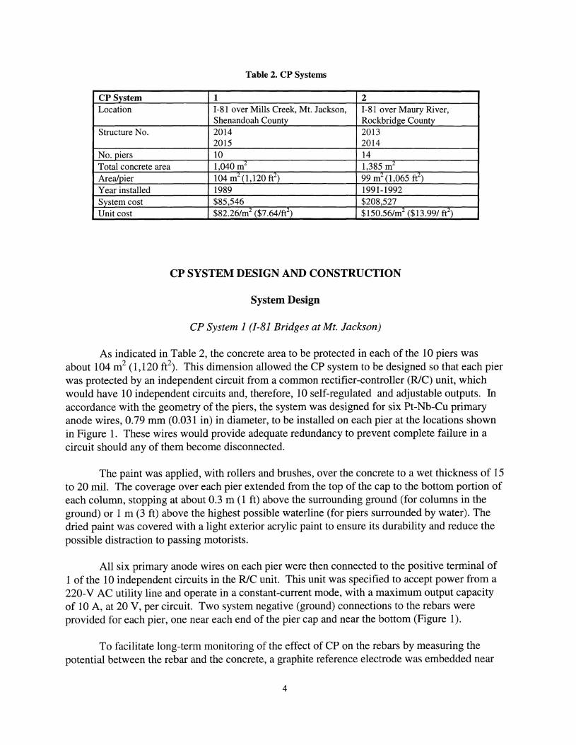
Table 2. CP Systems
CP System 1 2Location 1-81 over Mills Creek, Mt. Jackson, 1-81 over Maury River,
Shenandoah County Rockbridge CountyStructure No. 2014 2013
2015 2014No. piers 10 14Total concrete area 1,040 m2 1,385 m2
Area/pier 104 m2 (1,120 ft2) 99 m2 (1,065 ft2
)
Year installed 1989 1991-1992System cost $85,546 $208,527Unit cost $82.26/m2 ($7.64/ft2
) $150.56/m2 ($13.99/ ft2)
CP SYSTEM DESIGN AND CONSTRUCTION
System Design
CP System 1 (/-81 Bridges at Mt. Jackson)
As indicated in Table 2, the concrete area to be protected in each of the 10 piers wasabout 104 m2 (1,120 ft2
). This dimension allowed the CP system to be designed so that each pierwas protected by an independent circuit from a common rectifier-controller (RIC) unit, whichwould have 10 independent circuits and, therefore, 10 self-regulated and adjustable outputs. Inaccordance with the geometry of the piers, the system was designed for six Pt-Nb-Cu primaryanode wires, 0.79 mm (0.031 in) in diameter, to be installed on each pier at the locations shownin Figure 1. These wires would provide adequate redundancy to prevent complete failure in acircuit should any of them become disconnected.
The paint was applied, with rollers and brushes, over the concrete to a wet thickness of 15to 20 mil. The coverage over each pier extended from the top of the cap to the bottom portion ofeach column, stopping at about 0.3 m (1 ft) above the surrounding ground (for columns in theground) or 1 m (3 ft) above the highest possible waterline (for piers surrounded by water). Thedried paint was covered with a light exterior acrylic paint to ensure its durability and reduce thepossible distraction to passing motorists.
All six primary anode wires on each pier were then connected to the positive terminal of1 of the 10 independent circuits in the RIC unit. This unit was specified to accept power from a220-V AC utility line and operate in a constant-current mode, with a maximum output capacityof 10 A, at 20 V, per circuit. Two system negative (ground) connections to the rebars wereprovided for each pier, one near each end of the pier cap and near the bottom (Figure 1).
To facilitate long-term monitoring of the effect of CP on the rebars by measuring thepotential between the rebar and the concrete, a graphite reference electrode was embedded near
4

11.0 m --------------...1
To main conduit
+
I II I
1.5 m • I 1.5 mI I
L I I -l• I+. I.I II I
• JI II II II I
FRONT VIEW
To main conduit
REAR VIEW
TOP VIEW
Conductive coating covered with protective coating
Pt-Nb-Cu anode wires
f$i Test window
~ Graphite reference electrode
III- System ground connection
-0-+ PVC conduit (with conduits &clamps where needed)
Figure 1. Layout of CP System 1
5

the center of each pier cap. Further, to provide additional areas for potential measurements, four"test windows" (uncoated areas) 7.6-cm (3.0-in) square were provided on each cap. Thesewindows allow measurement of the rebar with a portable CU/CUS04 electrode.
CP System 2 (/-81 Bridges Over Maury River)
The layout design used for each of the 14 piers protected by this CP system was differentfrom that used in the first system, simply because of the difference in the pier geometries. Asillustrated in Figure 2, six Pt-Nb-Cu primary anode wires, two system ground connections, twographite reference electrodes, and four test windows were provided for each pier. All wereequally divided between the two faces. On each pier, the conductive paint was applied over theentire hammer-head cap and the top 7.2-m (25-ft) portion of the stem to a wet thickness of atleast 20 mil. As in System 1, a white exterior latex paint was applied over the dried conductivepaint at the rate of 4.9 m2/1 (200 ft2/gal).
Since the entire system required 14 independent circuits, two separate full-wave,unfiltered rectifiers were used. Each rectifier would had 7 independent circuits, each with amaximum output of 10 A, at 24 V.
Construction of the Systems
The procedures used to construct these CP systems were as follows:
1. Remove damaged concrete. The damaged concrete area was excavated to about 25mm (1 in) below the rebars to facilitate good bonding between the substrate and the pneumaticconcrete (shotcrete) used for patching. Before an excavated area was patched, the corrodedrebars were sandblasted in accordance with VDOT specifications. 12 Since using wires to tie thereinforcement together has been found to contribute to establishing electrical continuity betweenthe reinforcing steel, any tie wire damaged during the excavation was replaced.
2. Testfor electrical continuity between the rebars in each pier. To ensure that no rebarswould be left electrically isolated and, therefore, unprotected by the system, electrical continuitybetween many rebars in each pier was tested. This test was conducted by exposing some rebarsand measuring the DC resistance and voltage difference between different pairs of rebars.Typically, rebars at the ends of the caps and at the top and bottom of columns were tested. Inaddition, rebars that happened to be conveniently exposed at other locations, due to excavation ofdamaged concrete, were also tested after corrosion products were cleaned from the rebars. Ahigh-impedance multimeter with minimum resolutions of 0.1 Q and 0.1 mV was used in thesemeasurements. If the resistance between any two rebars was less than 1 Q or the voltagedifference was less than 1.0 mV, the rebars were considered to be electrically continuous. 13
When a rebar was found to be isolated, it was electrically bonded to a nearby rebar by thermitewelding of an insulated copper wire between them.
6

1......1---------------- 11.6 m --------------1.~1
D DPLAN VIEW
To RIC unit
--- ........... ----. I_ SN -_....... _"w.---
II II I I
l---------+---------~I
Conductive coating coveredwith protective coating
Pt-Nb-Cu anode wires
System ground connection
Test window
Graphite reference electrode
~ PVC conduit (with conduits& clamps where needed)
II
II
II
II
I :~------~~~~~~~~~~~~~~~~~~~~~-------1
: I :I I II I
: I :I I I
: 1 :
ELEVATION VIEWOF NORTH/SOUTH FACE
Figure 2. Layout of CP System 2
7
3. Testfor electrical continuity in all metallic appurtenances. Similarly, metallic items,such as drains, anchor bolts, etc., attached to the concrete were tested for electrical continuitywith the reinforcement. When necessary, they were bonded to the nearest reinforcement usingthe procedure described.
4. Install system ground connections and reference electrodes in each pier. On eachpier, two system ground connections were established at designated locations, as shown in eitherFigure 1 or 2. This was performed by locating, with a pachometer, a rebar in a designatedlocation and excavating enough concrete to expose it. The rebar was cleaned and then brazed byexothermic welding to an insulated copper lead wire. The connection was sealed with an epoxypaste to prevent moisture intrusion before the excavation was backfilled with concrete. The leadwire was routed all the way to the negative terminal of one of the output circuits in the RIC unit.
Similarly, graphite reference electrodes were embedded in each pier at specifiedlocations. Procedures for their installations are described elsewhere. I3 After each referenceelectrode and its corresponding negative connection were installed, the location was backfilledwith concrete patching materials. The concrete was allowed to cure before the half-cell potentialof that reference electrode and the AC resistance (between the electrode and the ground) werechecked to ensure that the reference electrodes were installed properly. If the potential readingsfluctuated by more than ±20 mV in 10 minutes and the AC resistance was greater than 10,000 Q,
the reference electrode was considered faulty and was replaced.
5. Patch the excavated areas. Excavated areas were patched with pneumatically appliedmortar in accordance with VDOT specifications. 12 If an excavated area was large and it wasnecessary to tie a small piece of steel mesh between the rebars to hold the applied mortar inplace, only nongalvanized steel mesh was used. The mesh was installed such that its edges weremore than 3.8 cm (1.5 in) below the finished surface.
6. Mask or electrically insulate any exposed metal wire at the concrete surface. Inconcrete piers, tie wires or chairs, which may be in contact with the rebars, frequently stick outfrom the bottom side of the pier caps. Such small items were located with a portable holidaydetector and then masked with a sealant made of vinyl ester resin. This would prevent theconductive paint from coming into contact with these small wires, during its application, andthereby creating electrical shorts, which would disable a CP circuit.
7. Mask the edges ofmetallic appurtenances and their surrounding concrete. Anotherpotential cause of electrical shorts in a CP system is the anode coming into contact with anymetallic component attached to the concrete, especially when the component is in contact withthe reinforcement. To ensure this was avoided, the edges of each metallic component and thesurrounding concrete (to 7.5 cm or 3 in) were tightly covered with duct tape before theconductive paint was applied on the concrete. The tape was removed after the paint had dried.
8. Mask concrete at several selected designated locations on the piers. These locations,as shown in Figures 1 and 2, were covered with duct tape to prevent them from being painted
8

over by the conductive paint so that these locations can be used as "windows" for measuring therebar-to-concrete potential with a portable CU/CUS04 half cell.
9. Install Pt-Nb-Cu primary anode wires on each pier. This installation involved tapinga Pt-Nb-Cu wire in place with an adhesive mesh tape and then covering it with a conductivepaste (see Figure 3). One end of each primary anode wire was then securely connected to aninsulated copper lead wire, which in turn was routed through a PVC conduit to the positiveterminal of a rectifier output circuit.
10. Apply two coats of the conductive paint. Immediately before application of theconductive paint on a pier, the concrete was thoroughly cleaned by light sandblasting. Then, thepaint was applied with rollers and brushes pier to yield a total wet thickness of at least 15 to 20mil.
11. Apply an overcoating. After the conductive paint had dried, an exterior acrylic paintwas applied over it. It is uncertain if this overcoating provides any function other than improvingthe appearance of the coated piers.
12. Install a PVC conduit system. A system of PVC junction boxes and conduits wasinstalled on the concrete piers and on the entire length of the bridges to route the necessarywiring from the piers to the RIC units at the selected end of the bridges. All critical electricalconnections, e.g., connections between primary anode wires, system ground connections,
Pt-Nb-Cu Anode Wire
Conductive Anode Paste(RW-23018)
Adhesive FiberglassMesh Tape
Protective Coating
15-mil ConductiveCoating (RW-23698)
0D~ V V
Owww0Q D Ow'.·
Q~ 0 aQ
(J D Concrete(] V- v
_<J 00 +0
.... v0
Figure 3. Installation of Anode Wires on Concrete Surface
9

reference electrodes, and their respective lead wires, were located in junction boxes to allow easyaccess. The selection of which end of the bridge(s) to locate the RIC unites) is often dictated bythe location of existing power lines.
13. Inspect the wiring. This inspection was carried out to verify and ensure that allwiring was properly installed and correctly connected to the rectifier(s). Although unthinkable,there had been reports of at least one incidence wherein the contractor had connected the systemgrounds to the positive terminals and the anodes to the negative terminals of the rectifiers. Anyanomaly must be corrected before the system is energized.
14. Activate and adjust the rectifier unit(s}. After the rectifier(s) was properly installedand grounded to a ground electrode, it was connected to a 220 VAC electric utility line. Eachrectifier was then activated. This was followed by determining the CP current required of eachcircuit to adequately protect the concrete pier to which it was assigned. For each circuit, this wasdetermined by performing an E-Iog I analysis, wherein the circuit current output (from therectifier) is increased incrementally and, at each interval, the IR-drop free potential of the rebar,relative to the embedded reference electrode, is measured. The CP current required from acircuit to protect its pier is the current value, in a E-vs-Iog I plot, at which oxygen reduction atthe cathode begins, which often coincides with the beginning of a linear trend. 14 On the basis ofsuch testing or engineering judgment, whenever it was difficult to determine the linear portion ofan E-vs-Iog I plot, the required current output for each circuit was adjusted accordingly and leftto operate in constant-current mode for approximately 30 days.
15. Retest each circuit after approximately 30 days ofoperation. To ensure that thecurrent output from each circuit was providing sufficient protection or polarization of the rebars,a depolarization test was conducted on each circuit. This test was conducted by interrupting theprotective current from a circuit and monitoring the decay of the IR-drop free potential for 4hours. If the extent ofrebar depolarization in 4 hours was at least 100 mY, the protection currentprovided by the circuit was considered sufficient; otherwise, the current output was adjustedhigher and operated at that level for 24 hours before restesting. 13
,14 After it was determined thatall circuits were providing the sufficient amount of current to protect the rebars, each system wasleft to operate continuously.
Monitoring the CP Systems
System parameters such as circuit voltage, circuit current, and rebar potential weremeasured during site visits, which were made as often as possible. For trial purposes, a remotemonitoring device was added to System 1 to facilitate checking of the operation of its rectifiersystem from any remote location equipped with a modem and a PC. Basically, such devices arecomposed of a modem card, a power supply, and several circuit cards containing signalconversion (i.e., analog-to-digital) and signal conditioning devices. A remote monitoring deviceis typically not a standard part of a rectifier, and its addition would not interfere in any way withthe normal function of a rectifier. The 4-hour depolarization tests, which are relatively moretime-consuming, were also performed during some site visits. Electronic advancements since the
10

installation of these CP systems have made it possible to conduct this depolarization testremotely.
RESULTS
Table 2 shows that the unit costs were $82.26/m2 ($7.64/ft2) and $150.56/m2 ($ 13.99/ft2)
for System 1 and 2, respectively. Unfortunately, because the bids for both CP systems were inlump sums, no breakdown of the costs can be provided for examination. Although twocontractors were involved, it is believed that this factor contributed little, if any, to the largedifference between the costs of the two systems. It is more likely that the considerably higherunit cost for installing System 2 was due to the greater height of the piers involved, which werecomparatively more difficult to work with.
Not surprisingly, some rebars in a few of the piers were found to be isolated from the rest.To correct this, the isolated rebars were exothermically welded to nearby continuous rebars. Forboth bridges at Mt. Jackson, all the bearing pins and pads and storm drains (attached to the fourpiers at the ends of both structures) were also found to be discontinuous; they were alsoexothermically welded to a wire, which was then connected to the system ground at the junctionbox above each pier. Because of the relatively high solids content of the conductive paint, 73percent by weight, its application on the concrete piers with rollers required appreciable effort.Nothing else of note was observed.
Effectiveness of Cathodic Protection
CP System 1
Since it was energized in late November 1989, the operation of System 1 had beenfollowed for close to 6 years. Table 3 provides its initial DC settings (protection current and
Table 3. Initial Rectifier Settings for CP System 1 and Rebar Potentials (as of December 1989)
Potential (V)Circuit Structure Pier Current (A) Voltaee (V) Static On1 2014 1 0.18 3.7 -0.134 -0.4782 (NBL) 2 0.15 1.8 -0.050 -0.4553 3 0.10 3.8 -0.056 -0.4484 4 0.15 4.8 -0.073 -0.5225 5 0.12 5.1 -0.040 -0.4686 2015 1 0.26 5.3 -0.101 -0.5207 (SBL) 2 0.08 4.9 -0.048 -0.5958 3 0.26 8.5 -0.073 -0.5419 4 0.10 4.7 -0.056 -0.57810 5 0.25 6.3 -0.142 -0.765
11

driving voltage) and the corresponding rebar potentials. In terms of current density, the initialcurrent settings were 0.79 to 2.48 mAlm2 (0.073 to 0.23 mAlft2
). With the driving voltageranging from 1.8 to 8.5 V, the corresponding resistance of these circuits ranged from 12 to 61 Q,
which was relatively high compared to those using metallized zinc coating as the anode.
The behavior of the 10 circuits is illustrated in Figures 4 to 13 for each pier. As thecurrent-vs-time plots show, in general, the RIC unit maintained the current level required of eachcircuit, except for occasional deviations attributable, perhaps, to short-term, rapid fluctuations inthe electrical resistance of the coating and the concrete, particularly during rain.
It is noteworthy that the driving voltage for each circuit increased slowly during the first1.5 years of operation of the system, then reached a reasonably stabilized level for the last 4 to 5years. Except for circuit 5, the average driving voltages for the other circuits fluctuated around 9to 15 V, which is well within 75 percent of the full capacity (20 V) of the rectifier. This behavioris expected when a system is operated galvanostatically, i.e., under constant current. This can beattributed to an increase in the electrical resistance of the concrete, the paint/concrete interface,the steel/concrete interface, or some combination of these factors. The former, in turn, is aconsequence of the redistribution of ions in the concrete, including the outward migration ofchloride ions. Therefore, the concern that the conductive paint might degrade too much and toosoon, after only a few years of being under an electrical charge, is unwarranted. As long as theconductive paint stabilizes and the driving voltage for each circuit remains at about 75 percent, orslightly higher, of its full capacity, the CP system should be fine.
The rebar potentials in all 10 piers shifted, within the first year of operation, toward beingmore positive before reaching stabilized levels. This unexpected shift may reflect the knownsensitivity of graphite electrodes to pH changes it their surroundings, which in this case isexpected to occur in the concrete surrounding the rebars when they are cathodically protected.The shift will be toward the desirable higher pH. Another possible explanation is that graphitetends to absorb many species at the more active crystal planes on its surface, and when the rightspecies are present in the concrete, the anodic reaction on the surface of the graphite electrodecan be sufficiently poisoned or inhibited, resulting in a positive drift in the potential.
More important, this temporary drift did not hinder depolarization testing of the circuits,which was conducted several times during the first 7 years of operation (see Table 4). As theresults of these tests indicated, the mean 4-hour depolarization ranged from 145 to 257 mV,which was higher than the generally accepted NACE criterion of 100-mV depolarization forsufficient CPo In only four tests, each involving a different circuit, did a circuit yield less than100-mV depolarization. In two, only slight increases in the current settings for the circuitsinvolved were required to obtain the minimum 100-mV depolarization. In the other two cases,wherein the depolarization was only 18 (for circuit 9 on 07/21/92) and 26 (for circuit 7 on05/02/96), the underlying reason was malfunctioning of the electronic components, which werereplaced without much difficulty. These depolarization results confirmed that the system is, ingeneral, providing more than adequate protection to the 10 concrete piers.
12

Circuit 11.4
1.2
1.0Q)
CD 0.8c.E« 0.6
Uo 0.4 .;
0.2 r' ~~,.: .. ;· · · f;.' til':· ..
~ .'Jt,. ..0.0 ..: ..
a 500 1000 1500
Time (day)30
25
2000 2500
Q) 20C)m......~ 15
Uo 10
., • 4· • •
0'0 500 1000 1500 2000 2500
Time (day)0.0
-0.2I$fi. .:=
.: · i .)i., .
-0.4 ..t· ·~~...- .... ...
..--....-0.6
.~ ......... , .~
!
'"'-"" -0.8 -W .-1.0
-1.2
-1.40 500 1000 1500 2000 2500
Time (day)Figure 4. DC Current, Voltage and Rebar Potential for Circuit 1, CP System 1, Since Installation in 1989.
13

Circuit 21.4
1.2
Q) 1.0L..Q)
~O.8
« 0.6()0
0.4 ~
;j.. -::..i.0.2 it~)f...~ ·
f· I"~: .. .... ..,.~. .,...: .. •
0.0 I.' ·
0 500 1000 1500 2000 2500
Time (day)30
25
Q) 20C') ..m....... ~ ..~
,....~ .15 .. ~. ~.' . ~... . : ...
0 \I•••~ ,-..... ,,-
0 10 i:: :i.;':;l!~'~I::' ...
5 ,'~ :: -:-: i.::'. ·..
00 500 1000 1500 2000 2500
Time (day)0.0
-0.2 . ,..;' ..' .....• .; ~::;2' •• Ie
-0.4 tit ·... :~ .~~ ;: . ~.. . .,...--.. .,..... -0.6~
: ,'--'"
W -0.8 .
-1.0
-1.2
-1.40 500 1000 1500 2000 2500
Time (day)Figure 5. DC Current, Voltage, and Rebar Potential for Circuit 2, CP System 1, Since Installation
14

Circuit 3
1.4
1.2
Q)1.0
L-Q)
0.8c.E« 0.6UCl 0.4
0.2 ~~;~.i l ·~ 1:'. •· -:-isr,. ~.•.0.0 ....,.",
o 500 1000
I..,
1500 2000 2500
Time (day)30
25
250020001500
• I
~.
1000
..:. ., .:
" ..- .
500
~. :~g..:~ ~,.! ~ ~.!!-;~:: :
5 ·.ft3'.: -: .• _.. :,.!'~
o L-'_....I..------I_--L-_.....L.-_.L---'-_---'---_...L------""_---J
o
& 20co......~ 15
UCl 10
Time (day)0.0
-0.2
-0.4
...--...~ -0.6
~~ -0.8
-1.0
e •.. ~.
-1.2
2500200015001000500-1 .4 -+--- ---r----'T"""-~-..--__r-___r_---.---~_____,
oTime (day)
Figure 6. DC Current, Voltage, and Rebar Potential for Circuit 3, CP System 1, Since Installation
15

Circuit 41.4
1.2
250020001500
.,.1000
:
... ~.~: ~o2 · ·i;·;~·
. I.· ~.~~.--..•.. •• 1....,
0.0 L.-----L--=-----L_-.L-_--I..-_--I.-_...L.-_....L...-_L-----L_----J
o 500
a> 1.0....a>a. 0.8E«o 0.6
o0.4
Time (day)30
25
25002000
.. .- - - ... - - - -- -
15001000
10I
.~...,.
5 ~l.
00 500
a> 20C)CO~
~ 15(.)o
Time (day)
0.0
...~
~. I
·~I···J' •
-0.2 .. - ., .-• •\,e""'. '" •. J'j,:: }l·
-0.4 t·: :..:.,...;~ . .
.............Q -0.6 1; :~ ;.~ -0.8
-1.0
-1.2
2500200015001000500-1.4 -f---~------r-__r_---r-----r---~-~~-~----,
oTime (day)
Figure 7. DC Current, Voltage, and Rebar Potential for Circuit 4,CP System 1, Since Installation
16

Circuit 51.4
1.2
a> 1.0L-a>C- 0.8E« 0.6()0 0.4
..:
::~ :.! I
0.2,..' .~.....-:, •...: .:. ·l.:r~~,
0.0.~ ...
0 500
: .,.:. .•J. •~.... .
1000
....J •
1500 2000 2500
Time (day)
30
25 . ,:..
5~
.'
2500200015001000500Ol..-- ----L_----L._----L....._---&....._......I...-_-'--_...I-_...&....------I
oTime (day)
0.0
-0.2
-0.4...--....~.g -0.6
~ -0.8
-1.0
:....
-1.2
2500200015001000500-1 .4 -4---....--_.-------,.---.----...---....,--__-..-----..-_
oTime (day)
Figure 8. DC Current, Voltage, and Rebar Potential for Circuit 5, CP System 1, Since Installation
17

Circuit 61.4
1.2
250020001500
.:..;.
1000
\\ .:"'.J... :
O.0 l...------..I._--I-_....:....&--_---&.-_.....L-.-_~___IL..._____L_ __L.._ ___J
o 500
a> 1.0L-a>c. 0.8E« 0.6Uo 0.4
..: I.';: "o2 t .,;;;. .. :~~:._~
Time (day)30
25
a> 20C)co
+-'
~ 15
g 10' :\ ::. .'t...... · ·· ,S1~ ~_.-----~t·-,:,~ ---:.- ----.- f __ - - - ~ - - - ~ - - - - - - - - .! - -- . ,- , ,. .
5 · .. ..,.,-; •
o &...-&._....a.....------a.._----&...-_....L.---.L._---a.-_..L.---L.._---L....------I
o 500 1000 1500 2000 2500
Time (day)
0.0
-0.2.~~,,:..~ ;:; .~.
-0.4 }i;, ~\. ,,.. \i . .-..- :t~ ·'::.::~ '.;...... -0.6 ~.:~ ;
~ '~ -0.8 !
-1.0
-1.2
-1 .4 -+-----------.---.....---.......-----.-----....--....------,
o 500 1000 1500 2000 2500
Time (day)Figure 9. DC Current, Voltage, and Rebar Potential for Circuit 6, CP System 1, Since Installation
18

Circuit 71.4
1.2
Q) 1.0L.Q)c. 0.8E« 0.6 .oo 0.4 .:. ..:
:: • t0.2 4·:':~:
~U!:.i ~ .~.,1.:1": 10-"' .... I0.0 · .~ .•.o 500
:. :.
1000
· t· · :
1500 2000 2500
Time (day)30
25
Q) 20C)co.......g 15
g 10
..• ,!II..~~O'-:..~! • ••"-..~ _... ,.~::
..~ I I
- - -~"..:;:" - -:.- - - ~ ,"" - - -I· .,
5 ",'.1l
I·..;.~
2500200015001000500OL...-----&._.--L._----'--_-.L.-_.....I.--_...L...-._.L...-------I_----L_----J
oTime (day)
0.0
. ~.
-1.2
2500200015001000500-1 .4 ~-,.......__ -____r_-~-,.._---r---r----r--......____
oTime (day)
Figure 10. DC Current, Voltage, and Rebar Potential for Circuit 76, CP System 1, Since Installation
19

Circuit 81.4
1.2
a> 1.0L-
a>E0.8
«U 0.6
o0.4
0.2 ~.~.. ~ .~..:.' ·;., ?',.... ..;;...:..~.~.: .,:..
I'
500 1000 1500 2000 2500
TIME (day)30
25
~ 20co......,~ 15 •.." • iU t.. f.~:··.. ·.... .. ~ .o 10 • ~Io ' ... - -- - - - .. ~ - _. - - -!..-. -- . ~- -- --
,~;;~~; ~ .s· ·5 · · 'if·
1000 1500
Time (day)
00
0.0
-0.2
-0.4~....... -0.6~'-'"
-0.8W
-1.0
-1.2
500
It;;i!~:: {j~.;•• • ':a •• :,.
· if •1:.~,~
It·. · i
2000 2500
-1 .4 -+---r-------'T'"----r---~____,r_________r_-..........._-~___.-___,
o 500 1000 1500 2000 2500
Time (day)Figure 11. DC Current, Voltage, and Rebar Potential for Circuit 8, CP System 1, Since Installation
20

Circuit 91.4
1.2
1.0(J)
CD 0.8c..~ 0.6
UCl 0.4
1500 2000 2500
Time (day)30
25
~ 20co.......~ 15
(...)o 10
500
-..
1000
...
1500 2000 2500
Time (day)0.0
I •
t:. •. ..
-0.2i ...
O 4 f .. : ..~ ...•..-. . .... ..:....--.. .,~::,:-; .~ :1:,·: i' .
o -0.6 ':·i:·: ::;. :..> .~ -0.8 ..
I
-1.0
-1.2
2500200015001000500-1 .4 -+---------------,-------...--.....---,.--........------.
oTime (day)
Figure 12. DC Current, Voltage, and Rebar Potential for Circuit 9, CP System 1, Since Installation
21

Circuit 101.4
1.2
1.0
25002000
"1000 1500
Time (Days)500
i·'"' _. ~: ~~~::.'C ~ '. f'
. \-=..... ,.ti .. -:w- -.:I. .~.'.:
O.0 -+---r-----r---r---r--~__+-~-__r__-~___.
o
CDCD 0.80..
~ 0.6
()o 0.4
0.2
30
25
1000 1500 2000
Time (Days)
~ 20ca
+oJ
0 15>()
100
5
00
0.0
-0.2
-0.4
..............-0.6....
~""-" -0.8W
-1.0
-1.2
..
500
,·r
.. .
... ~
2500
2500200015001000500-1 .4 -+---,......-__----r--~-~___._-~-__r__- _
oTime (day)
Figure 13. DC Current, Voltage, and Rebar Potential for Circuit 10, CP System 1, Since Installation
22

Table 4. Depolarization Tests for CP System 1
4-Hour De,aolarization (mV)Circuit 12/19/89 05/02/90 08/21/90 12/05/90 07/21/92 06/21/93 05/02/961 182 126 68 126 153 218 1312 206 201 166 105 165 192 1043 236 189 176 147 183 209 1374 265 194 205 139 186 204 1605 262 225 135 88 186 249 1326 248 214 252 172 206 177 1907 297 209 214 240 191 175 268 268 227 181 130 184 189 1259 319 288 259 123 18 306 18610 286 179 178 177 131 229 258Mean 257 205 183 145 160 215 145
Regardless of the real causes, the unexpected temporary positive shifts in the potentialsmay indicate that a graphite electrode lacks stability and would, therefore, not be an idealreference electrode for use in long-term monitoring of a CP system.
Current remote monitoring technology allows data to be measured remotely, stored, anddownloaded to any remote PC in different spreadsheets. The tedious 4-hour depolarization testcan also be performed remotely. In comparison, the remote monitoring device added to System 1was relatively crude. Nevertheless, the device basically functioned as intended and allowed theCP system to be checked and the operating parameters measured more often than would bepossible by site visitations alone, as evident by the amount of data collected (Figures 4 to 13).The device was damaged several times, each necessitating the replacement of a circuit card or acircuit component. It is believed that this damage was caused by lightning-related surges, whichcan be reduced significantly, if not completely, by providing better safeguards against suchsurges.
During the 8-year operation of System 1, the following rectifier components becamedefective at some time: DC fuses, rectifying elements, and, less often, switches and controllercards. Other minor problems, such as loose wire connections to terminals located in the frontpanel of the RIC unit and the connection between a lead wire and one of the primary wire anodes,also occurred. As a whole, System 1 was operating reasonably well and was providing sufficientprotection to the concrete piers.
CP System 2
Tests conducted for continuity between rebars and for resistance between the conductivepaint and the system grounds on the piers indicated that System 2 was installed properly. Theonly exception was the unusually high resistance (70 kQ) for one of the two graphite referenceelectrodes on pier 4 of the southbound bridge, the one embedded on the south face, which shouldhave been replaced by the contractor. Although this high resistance did not hinder E-vs-Iog I anddepolarization testing with the electrode, the first depolarization test using the electrode yielded a
23

depolarization of only 36 mY, in contrast to the 232 mV depolarization with the referenceelectrode embedded on the other face of the same pier. Although the environments surroundingthe two electrodes and, therefore, the extent of polarization achieved on the nearby rebars, cannotbe expected to be identical, the considerable discrepancy was probably a good indication that thefirst electrode was either defective or not installed properly.
The initial settings for the system and the rebar potentials following system startup arepresented in Table 5. The results of depolarization tests conducted at different times arepresented in Table 6. These data indicate large differences between the rebar potentialsmeasured at the north and the south faces of some piers, such as in piers 2 and 6 of thenorthbound bridge and pier 4 of the southbound bridge. In fact, slightly smaller differences wereobserved in some other piers.
Further, as Table 6 shows, there were differences in the extent the rebars in these twofaces depolarized, especially during the first set of depolarization tests, i.e., those conducted on09/21/92. In those tests, in 11 of the 14 piers, the extent of the 4-hour depolarization was higheron the north face (cellI) than on the south face (cell 2). Such difference was also reflected in thelater two sets of depolarization tests, although to a slightly lower degree. This apparent effect ofthe orientation of a vertical concrete structure on the potential readings warrants additional study,since the resulting large variations in potentials for the same structure can make it difficult to setthe circuit current so that the possibility of overcharging the conductive paint anode on the facesthat are easier to polarize is avoided.
The results from all of the depolarization tests (Table 6) indicated that, except for theinadequate polarization in the south face of some piers on 03/02/95, System 2 was providingadequate CP to the rebars. It must be emphasized that, since in many instances it took actuallymore than 4 hours for rebars to completely depolarize, the actual polarization of the rebars inthose instances was likely to be greater than those observed in 4 hours.
Table 5. Initial Rectifier Settings for CP System 2 and Rebar Potentials (as of 1992)
Current Voltage Potential (mV)Structure Pier Circuit (A) (V) CellI Cell 22013 1 N1 1.08 7.1 -0.829 -0.400(NBL) 2 N2 1.14 7.2 -2.510 -0.428
3 N3 0.68 7.4 -0.681 -0.3984 N4 0.46 3.2 -0.540 -0.7225 N5 0.28 2.7 -0.662 -0.5536 N6 1.18 8.0 -1.170 -0.2557 N7 1.44 8.0 -0.036 -0.536
2014 1 Sl 0.3 3.8 -0.241 -0.406(SBL) 2 S2 0.4 3.8 -0.726 -0.550
3 S3 0.2 5.2 -0.554 -0.2484 S4 0.3 5.0 -0.939 -0.2265 S5 0.4 4.5 -0.307 -0.2816 S6 0.2 6.2 -0.372 -0.2577 S7 0.2 4.6 -0.276 -0.307
24

Table 6. Depolarization Tests for CP System 2
4-Hour Depolarization (mV)Circuit Cell 09/21/92 03/02/95* 08/15/96N1 1 494 210 240
2 303 179 153N2 1 803 599 405
2 283 115 137N3 1 373 243 205
2 211 127 130N4 1 296 317 256
2 219 397 184N5 1 208 292 211
2 356 109 255N6 1 552 417 358
2 159 140 165N7 1 274 84 126
2 246 199 178Mean 341 248 21481 1 84 63 133
2 119 77 14882 1 515 160 464
2 178 92 13983 1 254 66 92
2 77 n.a. 584 1 232 107 185
2 36 40 7285 1 107 134 156
2 105 47 12686 1 181 93 125
2 104 44 10587 1 119 61 104
2 120 84 127Mean 159 82 141
*Reference 15.
It also appeared that cell 2 in pier 3 of the southbound bridge may have becamedefective and should be investigated. This and the extremely high resistance reported earlier forone of the reference electrodes may indicate that System 2, especially its electrical portions, wasnot installed as well as System 1. In fact, different general construction contractors wereinvolved in the installation of the two systems.
Deterioration of the Conductive Paint
A desirable characteristic of any CP system using conductive paint as the secondaryanode is that small and isolated areas of deterioration or damage in the paint, within some limit,do not interfere with the effectiveness of the system. To determine the rate of the deterioration,the paint in both systems was inspected with the aid of a new digital image analysis method for
25

peeling, staining, cracking, etc. This method, which was recently developed for quantitativeestimation of the extent of paint or coating damage on structural steel members, is composed ofthe following procedures: taking photographic slides of both sides of each pier, transformingthese analog images of the pier into digital image files (by scanning the slides with a digitizingscanner), and then using a suitable digital image analysis software to estimate the total area ofdamaged coating on each pier. 16 The paint was also inspected visually.
Table 7 lists the extent of the damage to the paint on each of the 10 piers protected bySystem 1, which is 8 years old. As indicated, the damage ranged from 0 to 2.50 m2
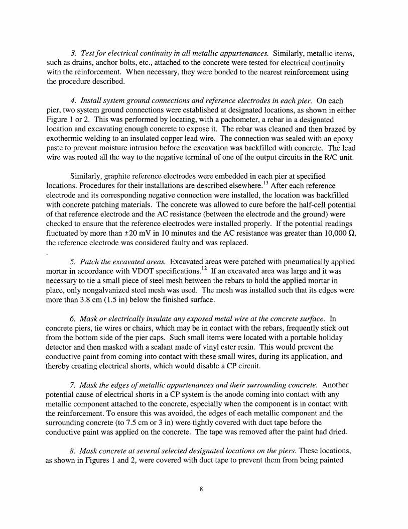
, or 0 to 2.40percent, of the total painted area on each pier. In comparison to the damage on most of the piers,the damage of 2.40 percent on pier 3 of the southbound bridge was relatively large and unusual.Since the damage was restricted to the pier footing on the upstream side (Figure 14), it wasattributed to abrasion and impact damage caused by recent severe flooding that sent timber debriscrashing against the pier. When this unusual damage is excluded from consideration, the damagefrom natural degradation of the conductive paint system ranged from only 0 to 0.37 percent. Itmust be noted that most of the damage occurred on the ends of the pier caps (Figure 15), wherethey are not sheltered from rain by the bridge deck above. This indicates that such areas are moreexposed to rain, which may result in more discharge of current in those areas during rain and,therefore, relatively faster degradation of the paint. A consolation is that the concrete in suchareas in pier caps is typically considerably less susceptible to rebar corrosion, because it is notdirectly below deck joints. Nevertheless, this aspect will have to be considered carefully in thedesign of future CP systems of this type.
The damage to the conductive paint in System 2, which is approximately 6 years old, islisted in Table 8. Damage was observed on only 0 to 0.19 percent of the total painted area oneach of the 14 piers. This range of damage is consistent with that in System 1. Likewise, theslightly damaged areas on a few of these 14 piers were located mostly at the ends of the pier caps(Figure 16).
Table 7. Estimated Damage to Conductive-Paint Anode in CP System 1
Damaged CoatingStructure Pier (m2
) (%)*
2014 1 0.25 0.24(NBL) 2 0.20 0.20
3 0.04 0.044 0.22 0.215 0.37 0.37
2015 1 0 0(SBL) 2 0.28 0.27
3 2.50 2.404 0 05 0.01 0.01
Mean 0.39 0.37
* Based on total coated area on each pier.
26
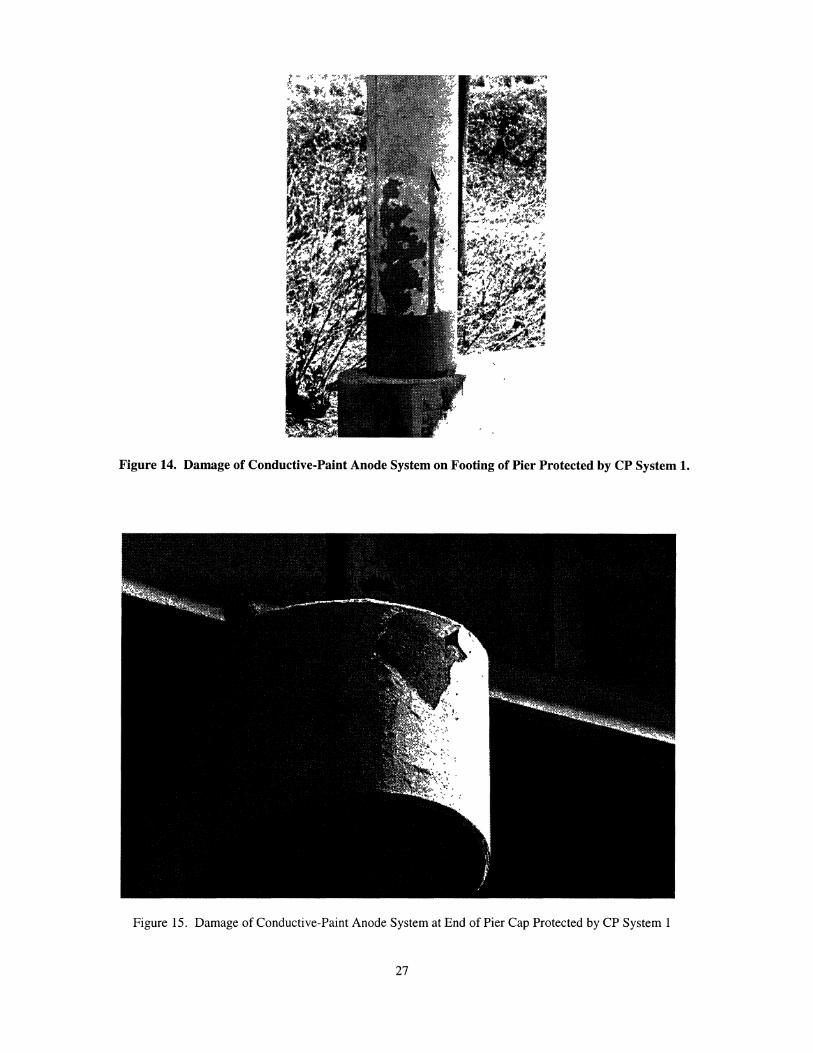
Figure 14. Damage of Conductive-Paint Anode System on Footing of Pier Protected by CP System 1.
Figure 15. Damage of Conductive-Paint Anode System at End of Pier Cap Protected by CP System 1
27

Table 8. Estimated Damage to Conductive-Paint Anode in CP System 2
Damaged CoatingStructure Pier (m2
) (%)*2013 1 0.02 0.02(NBL) 2 0 0
3 0 04 0 05 0.02 0.026 0.19 0.197 0.05 0.05
2014 1 0 0(SBL) 2 0.03 0.03
3 0 04 0 05 0 06 0 07 0 0
Mean 0.02 0.02*Based on total coated area on each pier.
Figure 16. Damage of Conductive-Paint Anode System at End of Pier Cap Protected by CP System 2
28

In general, the overall condition of the conductive paint in both systems appeared to bevery good, as shown in Figures 17 and 18. Therefore, it can be concluded that the conductivepaint anode is holding reasonably well, so far. It must be emphasized, however, that similar goodresults would likely not be obtained if the conductive paint was used on concrete members thatare constantly wet, e.g., concrete piles in marine environments, especially if the paint is appliednear the edge of the water. The important key to remember is that no paint or coating will lastlong when used on a substrate that remains wet all the time; the more frequent the substratebecomes wet, the faster the paint will deteriorate.
Figure 17. View of CP System 1 as of April 1977
Figure 18. View of CP System 2 as of November 1996
It is extremely difficult to predict how long the conductive-paint anode will last in thesetwo CP systems. Since the oldest application is already 8 years old and the existing natural
29

deterioration is relatively minor (no more than 0.37 percent), it is perhaps not unreasonable toexpect this anode system to last 15 years, or even more, especially if the existing minor damageis repaired reasonably early by touching up.
CONCLUSIONS
1. In general, the two CP systems, which used a water-based conductive paint as the secondaryanode, provide more than sufficient protection to the rebars in the inland concrete piers thesesystems were designed to protect.
2. As evident in the stabilization of the driving voltages and the minor deterioration of theconductive paint, after as long as 8 years of service, the concern about premature degradationof this type of secondary anode is unnecessary as long as the conductive paint is not used onconcrete members that will remain constantly wet.
3. The water-based conductive paint is a suitable alternative secondary anode for application inthe CP of concrete bridge piers in locations where the concrete stays dry most of the time.Even with such structures, it is advisable to consider safeguard measures to alleviate the slowdeterioration of the paint on portions of the concrete structures that become wetintermittently, including avoiding applying the paint on those portions of the concrete, i.e.,stopping the paint application at, say, 0.6 to 1 m (2 to 3 ft) from those portions. It cannot beoveremphasized that, just as with any paint, applying conductive paint on structures thatremain constantly wet is certain to result in failure.
4. When used in the right locations, it is reasonable to expect the conductive-paint anode to lastat least 15 years, especially if efforts are made to touch up any paint damage as early aspossible.
5. The relatively primitive remote monitoring unit (by current technological standards) usedwith the older CP system demonstrated that such equipment is extremely cost-effective andshould be incorporated in all new CP systems to eliminate the need for regular visits to asystem to determine if it is still operating properly.
6. It appears that graphite reference electrodes may not be suitable for long-term monitoring ofCP systems. Consequently, there is an urgent need to search for or develop more stablereference electrodes that can be embedded in concrete.
ACKNOWLEDGMENTS
The authors express their sincere appreciation to the FHWA's Office of TechnologyApplications for the valuable opportunity to evaluate the water-based conductive paint for
30

potential application in halting the costly problem of reinforcement corrosion in concrete bridgesthat is affecting not only Virginia, but many other states, too. Without their funding support, thisevaluation would probably be impossible.
The authors are indebted to S.F. Daily and B.J. McGrath for their valuable suggestionsand for reviewing this report. Appreciation is extended to R.W. Howe and A.W. French forassisting in this investigation.
REFERENCES
1. Page, C.L., Bamforth, P.B., and Figg, J.W., Eds. Proceedings of the Fourth InternationalSymposium on Corrosion ofReinforcement in Concrete Construction. Robinson College,Cambridge, U.K., July 1996.
2. Bennett, J.E., Thomas, T.J., Clear, K.C., Lankard, D.L., Hartt, W.H., and Swiat, W.J.Electrochemical Chloride Removal and Protection of Concrete Bridge Components:Laboratory Studies. SHRP-S-657. National Research Council, Washington, D.C., 1993.
3. Clemefia, G.G., and Jackson, D.R. Pilot Application ofElectrochemical Chloride Extractionon Concrete Bridge Decks in Virginia. Presented at the 76th Annual Meeting of theTransportation Research Board, Washington, D.C., January 1997.
4. Uhlig, H.H., and Revie, R.W. Corrosion and Corrosion Control: An Introduction toCorrosion Science and Engineering. John Wiley & Sons, New York, 1984.
5. Clemefia, G.G. A Slotted Cathodic Protection System for Bridge Decks. Proceedings of theConference on Cathodic Protection ofReinforced Concrete Bridge Decks. NationalAssociation of Corrosion Engineers, Houston, 1985.
6. Clemefia, G. Electrically Conductive Portland Cement Concrete. Materials Performance,Vol. 27, No.3, pp. 19-25, 1988.
7. Clemefia, G.G. Cathodic Protection ofTwo Concrete Bridge Decks Using Titanium-MeshAnodes and Latex-Modified Concrete Overlays. VTRC 90-WP5. Virginia TransportationResearch Council, Charlottesville, 1989.
8. Swiat, W.J., and Bushman, J.B. Further Improvements in Cathodic Protection. FHWA-RD88-267. Federal Highway Administration, Washington, D.C., 1989.
9. Schell, H.C., and Manning, D.G. Evaluating the Performance of Cathodic ProtectionSystems on Reinforced Concrete Bridge Substructures. Materials Performance, Vol. 24, No.7, pp. 18-25, 1985.
31

10. Norton Corrosion Engineers. James River Bridge Cathodic Protection System. Bothell,Washington, 1988.
11. Kenneth C. Clear, Inc. Laboratory Testing ofan Acheson Conductive Coating Formulatedfor Exterior Concrete Surfaces. Sterling, Virginia, 1987.
12. Virginia Department of Transportation. Road and Bridge Specifications. Richmond, 1987.
13. Task Force 29 Report, Subcommittee on New Highway Materials, AASHTO-AGC-ARTBAJoint Committee. Guide Specification for Cathodic Protection of Concrete Bridge Decks.Washington, D.C., 1994.
14. National Association of Corrosion Engineers. Standard Recommended Practice: CathodicProtection ofReinforcing Steel in Atmospherically Exposed Concrete Structures. NACEStandard RP0290-90 (Item No. 53072). Houston, 1990.
15. Islam, M., Sohanghpurwala, A.A., and Scannell, W.T. Evaluation ofa Cathodic ProtectionSystem: Pier Caps on Maury River Bridge, Lexington, Virginia. FHWA Turner-FairbankHighway Research Center, McLean, Virginia, 1995.
16. Howe, R.W., French, A.W., and Clemefia, G.G. The Use ofDigital Image Processing toEstimate the Amount ofPaint Peeledfrom a Bridge. Virginia Transportation ResearchCouncil, Charlottesville, 1997.
32