performance made smarter product manual
TRANSCRIPT

PERFORMANCEMADE
SMARTER
Product Manual 5725Programmable frequency indicator
TEMPER ATURE | I .S . INTERFACES | COMMUNIC ATION INTERFACES | MULTIFUNC TIONAL | ISOL ATION | D ISPL AY
No. 5725V103-UKFrom serial no. : 181101000

Communication
Display
I.S. Interface
Isolation
Multifunction
Temperature
6 Product Pillarsto meet your every need
With our innovative, patented technologies, we make signal conditioning smarter and simpler. Our portfolio is composed of six product areas, where we offer a wide range of analog and digital devices covering over a thousand applications in industrial and factory automation. All our products comply with or surpass the highest industry standards, ensuring reliability in even the harshest of environments and have a 5-year warranty for greater peace of mind.
Individually outstanding, unrivalled in combination
Our range of temperature transmitters and sensors provides the highest level of signal integrity from the measurement point to your control system. You can convert industrial process temperature signals to analog, bus or digital communications using a highly reliable point-to-point solution with a fast response time, automatic self-calibration, sensor error detection, low drift, and top EMC performance in any environment.
Our unique range of single devices covering multiple applications is easily deployable as your site standard. Having one variant that applies to a broad range of applications can reduce your installation time and training, and greatly simplify spare parts management at your facilities. Our devices are designed for long-term signal accuracy, low power consumption, immunity to electrical noise and simple programming.
We provide inexpensive, easy-to-use, future-ready communication interfaces that can access your PR installed base of products. The detachable 4501 Local Operator Interface (LOI) allows for local monitoring of process values, device configuration, error detection and signal simulation. The next generation, our 4511 Remote Operator Interface (ROI) does all that and more, adding remote digital communications via Modbus/RTU, while the analog output signals are still available for redundancy.With the 4511 you can further expand connectivity with a PR gateway, which connects via industrial Ethernet, wirelessly through a Wi-Fi router or directly with the devices using our Portable Plant Supervisor (PPS) application. The PPS app is available for iOS, Android and Windows.
Our display range is characterized by its flexibility and stability. The devices meet nearly every demand for display readout of process signals, and have universal input and power supply capabilities. They provide a real-time measurement of your process value no matter the industry, and are engineered to provide a user-friendly and reliable relay of information, even in demanding environments.
We deliver the safest signals by validating our products against the toughest safety standards. Through our commitment to innovation, we have made pioneering achievements in developing I.S. interfaces with SIL 2 Full Assessment that are both efficient and cost-effective. Our comprehensive range of analog and digital intrinsically safe isolation barriers offers multifunctional inputs and outputs, making PR an easy-to-implement site standard. Our backplanes further simplify large installations and provide seamless integration to standard DCS systems.
Our compact, fast, high-quality 6 mm isolators are based on microprocessor technology to provide exceptional performance and EMC-immunity for dedicated applications at a very low total cost of ownership. They can be stacked both vertically and horizontally with no air gap separation between units required.
5725V103-UK 3
Programmable frequency indicator
5725
Table of contentsWarning . . . . . . . . . . . . . . . . . . . . . . . . . . . . . . . . . . . . . . . . . . . . . . . . . . . . . . . . . . . . . . . . . . . . . . . . . . . . . . . . . . . . . . . . . . . . . . . . 4Symbol identification . . . . . . . . . . . . . . . . . . . . . . . . . . . . . . . . . . . . . . . . . . . . . . . . . . . . . . . . . . . . . . . . . . . . . . . . . . . . . . . . . . . . 4Safety instructions . . . . . . . . . . . . . . . . . . . . . . . . . . . . . . . . . . . . . . . . . . . . . . . . . . . . . . . . . . . . . . . . . . . . . . . . . . . . . . . . . . . . . . 4Front and back layout. . . . . . . . . . . . . . . . . . . . . . . . . . . . . . . . . . . . . . . . . . . . . . . . . . . . . . . . . . . . . . . . . . . . . . . . . . . . . . . . . . . . 5 Application . . . . . . . . . . . . . . . . . . . . . . . . . . . . . . . . . . . . . . . . . . . . . . . . . . . . . . . . . . . . . . . . . . . . . . . . . . . . . . . . . . . . . . . . . . . . . 6Technical characteristics . . . . . . . . . . . . . . . . . . . . . . . . . . . . . . . . . . . . . . . . . . . . . . . . . . . . . . . . . . . . . . . . . . . . . . . . . . . . . . . . . 6Mounting / installation. . . . . . . . . . . . . . . . . . . . . . . . . . . . . . . . . . . . . . . . . . . . . . . . . . . . . . . . . . . . . . . . . . . . . . . . . . . . . . . . . . . 6Applications . . . . . . . . . . . . . . . . . . . . . . . . . . . . . . . . . . . . . . . . . . . . . . . . . . . . . . . . . . . . . . . . . . . . . . . . . . . . . . . . . . . . . . . . . . . . 7Order . . . . . . . . . . . . . . . . . . . . . . . . . . . . . . . . . . . . . . . . . . . . . . . . . . . . . . . . . . . . . . . . . . . . . . . . . . . . . . . . . . . . . . . . . . . . . . . . . . . 8Accessories . . . . . . . . . . . . . . . . . . . . . . . . . . . . . . . . . . . . . . . . . . . . . . . . . . . . . . . . . . . . . . . . . . . . . . . . . . . . . . . . . . . . . . . . . . . . . 8Electrical specifications . . . . . . . . . . . . . . . . . . . . . . . . . . . . . . . . . . . . . . . . . . . . . . . . . . . . . . . . . . . . . . . . . . . . . . . . . . . . . . . . . . 8Sensor error indication, inside and outside range . . . . . . . . . . . . . . . . . . . . . . . . . . . . . . . . . . . . . . . . . . . . . . . . . . . . . . . . . . 11Connections . . . . . . . . . . . . . . . . . . . . . . . . . . . . . . . . . . . . . . . . . . . . . . . . . . . . . . . . . . . . . . . . . . . . . . . . . . . . . . . . . . . . . . . . . . . . 12Block diagram . . . . . . . . . . . . . . . . . . . . . . . . . . . . . . . . . . . . . . . . . . . . . . . . . . . . . . . . . . . . . . . . . . . . . . . . . . . . . . . . . . . . . . . . . . . 13Configuration / operating the function keys . . . . . . . . . . . . . . . . . . . . . . . . . . . . . . . . . . . . . . . . . . . . . . . . . . . . . . . . . . . . . . . 14Additional features (from s/n > 121435001) . . . . . . . . . . . . . . . . . . . . . . . . . . . . . . . . . . . . . . . . . . . . . . . . . . . . . . . . . . . . . . 14Additional features (from s/n > 181101000) . . . . . . . . . . . . . . . . . . . . . . . . . . . . . . . . . . . . . . . . . . . . . . . . . . . . . . . . . . . . . . 15Routing diagram for 5725A . . . . . . . . . . . . . . . . . . . . . . . . . . . . . . . . . . . . . . . . . . . . . . . . . . . . . . . . . . . . . . . . . . . . . . . . . . . . . . 16Routing diagram for 5725D . . . . . . . . . . . . . . . . . . . . . . . . . . . . . . . . . . . . . . . . . . . . . . . . . . . . . . . . . . . . . . . . . . . . . . . . . . . . . . 18Help text overview . . . . . . . . . . . . . . . . . . . . . . . . . . . . . . . . . . . . . . . . . . . . . . . . . . . . . . . . . . . . . . . . . . . . . . . . . . . . . . . . . . . . . . 20Graphic depiction of the relay function setpoint . . . . . . . . . . . . . . . . . . . . . . . . . . . . . . . . . . . . . . . . . . . . . . . . . . . . . . . . . . . 22Document history . . . . . . . . . . . . . . . . . . . . . . . . . . . . . . . . . . . . . . . . . . . . . . . . . . . . . . . . . . . . . . . . . . . . . . . . . . . . . . . . . . . . . . . 23

4 5725V103-UK
WarningThis device is designed for connection to hazardous electric voltages. Ignoring this warning can result in severe personal injury or mechanical damage.To avoid the risk of electric shock and fire, the safety instructions of this guide must be observed and the guidelines followed. The specifications must not be exceeded, and the device must only be applied as described in the following.Prior to the commissioning of the device, this installation guide must be examined carefully.Only qualified personnel (technicians) should install this device. If the equipment is used in a manner not specified by the manufacturer, the protection provided by the equipment may be impaired.
WarningUntil the device is fixed, do not connect hazardous voltages to the device. The following operations should only be carried out on a disconnected device and under ESD safe conditions: Troubleshooting the device.
Repair of the device and replacement of circuit breakers must be done by PR electronics A/S only.
Symbol identificationTriangle with an exclamation mark: Warning/demand. Potentially lethal situations.
The CE mark proves the compliance of the device with the essential requirements of the directives.
Safety instructions
Definitions
Hazardous voltages have been defined as the ranges: 75 to 1500 Volt DC, and 50 to 1000 Volt AC. Technicians are qualified persons educated or trained to mount, operate, and also trouble-shoot technically correct and in accordance with safety regulations. Operators, being familiar with the contents of this manual, adjust and operate the knobs or potentiometers during normal operation.
Receipt and unpacking
Unpack the device without damaging it and check whether the device type corresponds to the one ordered. The packing should always follow the device until this has been permanently mounted.
Environment
Avoid direct sun light, dust, high temperatures, mechanical vibrations and shock, and rain and heavy moisture. If necessary, heating in excess of the stated limits for ambient temperatures should be avoided by way of ventilation. All devices fall under Installation Category II, Pollution Degree 2, and Insulation Class II.
GENERAL
HAZARD- OUS
VOLTAGE

5725V103-UK 5
Mounting
Only technicians, who are familiar with the technical terms, warnings, and instructions in the manual and who are able to follow these, should connect the device. Should there be any doubt as to the correct handling of the device, please contact your local distributor or, alternatively,
PR electronics A/Swww.prelectronics.com
Mounting and connection of the device should comply with national legislation for mounting of electric materials, i.e. wire cross section, protective fuse, and location. Descriptions of Input / Output and supply connections are shown in the block diagram and side label.
The following apply to fixed hazardous voltages-connected devices:The max. size of the protective fuse is 10 A and, together with a power switch, it should be easily accessible and close to the device. The power switch should be marked with a label indicating that it will switch off the voltageto the device.
Year of manufacture can be taken from the first two digits in the serial number.
UL installation requirements
For use on a flat surface of a type 1 enclosure.Use 60/75°C copper conducters onlyEnclosure rating (face only) . . . . . . . . . . . . . . . . . . . . . . . . . . . . . Type 4X, UL50EMax. ambient temperature . . . . . . . . . . . . . . . . . . . . . . . . . . . . . . 60°CMax. wire size, pins 41...46. . . . . . . . . . . . . . . . . . . . . . . . . . . . . . AWG 30-16Max. wire size, others . . . . . . . . . . . . . . . . . . . . . . . . . . . . . . . . . AWG 30-12UL file number . . . . . . . . . . . . . . . . . . . . . . . . . . . . . . . . . . . . . E248256
Calibration and adjustment
During calibration and adjustment, the measuring and connection of external voltages must be carried out according to the specifications of this manual. The technician must use tools and instruments that are safe to use.
Normal operation
Operators are only allowed to adjust and operate devices that are safely fixed in panels, etc., thus avoiding the danger of personal injury and damage. This means there is no electrical shock hazard, and the device is easily accessible.
Cleaning
When disconnected, the device may be cleaned with a cloth moistened with distilled water.
Liability
To the extent the instructions in this manual are not strictly observed, the custom er cannot advance a demand against PR electronics A/S that would otherwise exist according to the concluded sales agreement.
Front and back layout
Picture 1: Front of 5725. Picture 2: Back of 5725.

6 5725V103-UK
Application
• The 5725 measures, scales, and displays frequency signals found in many process speed and flow rate applications.• The indicator can measure the period of the frequency, useful for displaying the elapsed time between events.• The 5725D has two SPDT setpoint contacts and a 0/4...20 mA output for process control.• The installed display provides IP65 environmental sealing, and additional protection is provided by the optional 8335
splash proof cover.
Technical characteristics
• 4 digit display w/13.8 mm high, 14 segment LED digits and adjustable decimal point.• Indicator is scalable from -1999 to 9999• Scrolling help text makes programming easy.• Built-in excitation source for measuring NPN, PNP, NAMUR and SO sensors.• Fast response time of 1 cycle + 100 ms, and excellent accuracy of better than 0.05% of selected range.• The analog output current on the 5725D can be dampened from 0.1 to 60 seconds, and can handle up to 800 Ohms loop
load.• The 5725 meets NAMUR NE21 recommendations, for high performance in harsh EMC environments.• High 2.3 kVAC galvanic isolation, and an excellent signal/noise ratio of > 60 dB.
Mounting / installation
• Easy to mount 1/8 DIN (48 x 96 mm) panel meter with IP65, (type 4X) sealing.• Approved for marine applications.• Fully push-button programmable.• Password protected.
Programmable frequency indicator
5725
• Measures NPN, PNP, Contact, NAMUR, SO, Tacho and TTL sensors
• Programmable frequency input span of 0.001 Hz to 50 kHz
• The 5725D has two SPDT relays and one analog output
• Easy to read 4 digit, 14 segment LED display with scrolling help text
• Universally powered by 21.5…253 VAC or 19.2… 300 VDC

S0
44
43
42
41
∼TTL
1 2
32
31
1 2
-
+
26
25
24
23
22
21
12
11
1 2
∼
∼
5725V103-UK 7
Applications
21.6...253 VAC or
19.2...300 VDC
Supply:
Output signals:
Input signals:
+ Supply 5...17 V
Contact (NPN)
Special trigcurrent & voltage
Relay 1
Relay 2
+ Input
Tacho
Input gnd
TTL S0 NAMUR PNP NPN Tacho
Analog, 0/4...20 mA
+ Supply + Supply

8 5725V103-UK
Order
Type Version
5725 Standard
Analog output and 2 relays
: A
: D
Accessories
8335 = Splash proof cover
Electrical specifications
Environmental conditions:Operating temperature . . . . . . . . . . . . . . . . . . . . . . . . . . . . . . . . -20°C to +60°C Storage temperature . . . . . . . . . . . . . . . . . . . . . . . . . . . . . . . . . -40°C to +85°C Calibration temperature. . . . . . . . . . . . . . . . . . . . . . . . . . . . . . . . 20...28°C Relative humidity . . . . . . . . . . . . . . . . . . . . . . . . . . . . . . . . . . . < 95% RH (non-cond.)Protection degree . . . . . . . . . . . . . . . . . . . . . . . . . . . . . . . . . . . IP20Installation in . . . . . . . . . . . . . . . . . . . . . . . . . . . . . . . . . . . . . . Pollution degree 2 & overvoltage category II.
Mechanical specifications:Dimensions (HxWxD) . . . . . . . . . . . . . . . . . . . . . . . . . . . . . . . . . 48 x 96 x 120 mmCutout dimensions . . . . . . . . . . . . . . . . . . . . . . . . . . . . . . . . . . . 44.5 x 91.5 mmProtection degree (mounted in panel) . . . . . . . . . . . . . . . . . . . . . . . IP65 / Type 4X, UL50EWeight . . . . . . . . . . . . . . . . . . . . . . . . . . . . . . . . . . . . . . . . . . 230 gWire size, pin 11-12 & 41-44, max. . . . . . . . . . . . . . . . . . . . . . . . . . 1 x 1.5 mm2 / AWG 30...16 stranded wireWire size, others, max. . . . . . . . . . . . . . . . . . . . . . . . . . . . . . . . . 1 x 2.5 mm2 / AWG 30...12 stranded wire Terminal connection . . . . . . . . . . . . . . . . . . . . . . . . . . . . . . . . . . Spring-cageVibration. . . . . . . . . . . . . . . . . . . . . . . . . . . . . . . . . . . . . . . . . IEC 60068-2-6 2...13.2 Hz . . . . . . . . . . . . . . . . . . . . . . . . . . . . . . . . . . . . . . ±1 mm 13.2...100 Hz . . . . . . . . . . . . . . . . . . . . . . . . . . . . . . . . . . . . . ±0.7 g
Common electrical specifications:Supply voltage, universal . . . . . . . . . . . . . . . . . . . . . . . . . . . . . . . 21.6...253 VAC, 50...60 Hz or 19.2...300 VDCMax. required power, 5725A / 5725D . . . . . . . . . . . . . . . . . . . . . . . 2.8 W / 3.6 WIsolation voltage, test / operation. . . . . . . . . . . . . . . . . . . . . . . . . . 2.3 kVAC / 250 VAC Signal / noise ratio . . . . . . . . . . . . . . . . . . . . . . . . . . . . . . . . . . . > 60 dB
Input specifications:Frequency range, f/I conversion function . . . . . . . . . . . . . . . . . . . . 0.001 Hz to 50 kHzLow cut off frequency (default value) . . . . . . . . . . . . . . . . . . . . . . . 0.0009 HzLow cut off frequency, (LCOF=YES) . . . . . . . . . . . . . . . . . . . . . . . . . 0.5 Hz (2 s)Max. frequency, with input filter ON . . . . . . . . . . . . . . . . . . . . . . . . 50 HzTime range, period time function . . . . . . . . . . . . . . . . . . . . . . . . . 999.9 s to 20 µsLow cut off period time . . . . . . . . . . . . . . . . . . . . . . . . . . . . . . . . 1111 sMin. period time with input filter ON . . . . . . . . . . . . . . . . . . . . . . . . 20 msResponse time (0...90%, 100...10%) . . . . . . . . . . . . . . . . . . . . . . . . < 1 period + 100 ms
Accuracy values
Specification Absolute accuracy Temperature coefficient
Input to Display & Relays ≤ ±0.05% ≤ ±0.01% / °C
Input to Analog Output ≤ ±0.1%
EMC - immunity influence. . . . . . . . . . . . . . . . . . . . . . . . . < ±0.5% of spanExtended EMC immunity:NAMUR NE 21, A criterion, burst . . . . . . . . . . . . . . . . . . . . < ±1% of span

5725V103-UK 9
Input types:NAMUR input - acc. to EN 60947-5-6:Trig-level LOW . . . . . . . . . . . . . . . . . . . . . . . . . . . . . . . . . . . . . ≤ 1.2 mATrig-level HIGH . . . . . . . . . . . . . . . . . . . . . . . . . . . . . . . . . . . . . ≥ 2.1 mAInput impedance . . . . . . . . . . . . . . . . . . . . . . . . . . . . . . . . . . . . 1 kΩ / < 1.5 nFBreakage detection . . . . . . . . . . . . . . . . . . . . . . . . . . . . . . . . . . ≤ 0.1 mA Short-circuit detection . . . . . . . . . . . . . . . . . . . . . . . . . . . . . . . . ≥ 6.9 mASensor supply - pin 44, fixed. . . . . . . . . . . . . . . . . . . . . . . . . . . . . 8.3 V
Tacho input:Trig-level LOW . . . . . . . . . . . . . . . . . . . . . . . . . . . . . . . . . . . . . ≤ - 50 mVTrig-level HIGH . . . . . . . . . . . . . . . . . . . . . . . . . . . . . . . . . . . . . ≥ + 50 mVInput impedance . . . . . . . . . . . . . . . . . . . . . . . . . . . . . . . . . . . . ≥ 100 kΩ / < 1.5 nFMax. input voltage . . . . . . . . . . . . . . . . . . . . . . . . . . . . . . . . . . . 80 VAC ppSensor supply - pin 44, programmable . . . . . . . . . . . . . . . . . . . . . . . 5...17 V / 20 mA
NPN / PNP input:Trig-level LOW . . . . . . . . . . . . . . . . . . . . . . . . . . . . . . . . . . . . . ≤ 4.0 VTrig-level HIGH . . . . . . . . . . . . . . . . . . . . . . . . . . . . . . . . . . . . . ≥ 7.0 VInput impedance . . . . . . . . . . . . . . . . . . . . . . . . . . . . . . . . . . . . 3.48 kΩ / < 1.5 nFSensor supply - pin 44, programmable . . . . . . . . . . . . . . . . . . . . . . . 5...17 V / 20 mA
TTL input:Trig-level LOW . . . . . . . . . . . . . . . . . . . . . . . . . . . . . . . . . . . . . ≤ 0.8 VDCTrig-level HIGH . . . . . . . . . . . . . . . . . . . . . . . . . . . . . . . . . . . . . ≥ 2.0 VDCInput impedance . . . . . . . . . . . . . . . . . . . . . . . . . . . . . . . . . . . . ≥ 100 kΩ / < 1.5 nFSensor supply - pin 44, programmable . . . . . . . . . . . . . . . . . . . . . . . 5...17 V / 20 mA
S0 input acc. to DIN 43864:Trig-level LOW . . . . . . . . . . . . . . . . . . . . . . . . . . . . . . . . . . . . . ≤ 2.2 mATrig-level HIGH . . . . . . . . . . . . . . . . . . . . . . . . . . . . . . . . . . . . . ≥ 9.0 mAInput impedance . . . . . . . . . . . . . . . . . . . . . . . . . . . . . . . . . . . . 758 Ω / < 1.5 nFSensor supply - pin 44, fixed. . . . . . . . . . . . . . . . . . . . . . . . . . . . . 17 V
Special voltage input:User programmable trig-levels. . . . . . . . . . . . . . . . . . . . . . . . . . . . -0.05...6.50 V Hysteresis, min . . . . . . . . . . . . . . . . . . . . . . . . . . . . . . . . . . . . . 50 mVInput impedance, selectable: High Z . . . . . . . . . . . . . . . . . . . . . . . . . . . . . . . . . . . . . . . . . ≥100 kΩ / < 1.5 nF Pull up and pull down . . . . . . . . . . . . . . . . . . . . . . . . . . . . . . . . 3.48 kΩ / < 1.5 nFSensor supply - pin 44, programmable . . . . . . . . . . . . . . . . . . . . . . . 5...17 V / 20 mA
Special current input:User programmable trig-levels. . . . . . . . . . . . . . . . . . . . . . . . . . . . 0.0...10.0 mAHysteresis, min . . . . . . . . . . . . . . . . . . . . . . . . . . . . . . . . . . . . . 0.2 mAInput impedance . . . . . . . . . . . . . . . . . . . . . . . . . . . . . . . . . . . . 1 kΩ / < 1.5 nFSensor supply - pin 44, programmable . . . . . . . . . . . . . . . . . . . . . . . 5...17 V / 20 mA
Output specifications:
Display:Display readout. . . . . . . . . . . . . . . . . . . . . . . . . . . . . . . . . . . . . -1999...9999 (4 digits) Decimal point . . . . . . . . . . . . . . . . . . . . . . . . . . . . . . . . . . . . . . Programmable Digit height . . . . . . . . . . . . . . . . . . . . . . . . . . . . . . . . . . . . . . . 13.8 mm Display updating . . . . . . . . . . . . . . . . . . . . . . . . . . . . . . . . . . . . 2.2 times / sDisplay response time, programmable . . . . . . . . . . . . . . . . . . . . . . . 0.0...60.0 s Input frequency outside range andNAMUR input sensor error is indicated by . . . . . . . . . . . . . . . . . . . . . Explanatory text

0,10 A
1,00 A
0 V 50 V 100 V 150 V 200 V 250 V
CUR
REN
T
URELAY
10 5725V103-UK
Current output (5725D):Programmable signal ranges . . . . . . . . . . . . . . . . . . . . . . . . . . . . . 0...20, 4...20 & 20...0, 20...4 mALoad (max.) . . . . . . . . . . . . . . . . . . . . . . . . . . . . . . . . . . . . . . . ≤ 800 ΩCurrent limit. . . . . . . . . . . . . . . . . . . . . . . . . . . . . . . . . . . . . . . ≤ 28 mA Load stability . . . . . . . . . . . . . . . . . . . . . . . . . . . . . . . . . . . . . . ≤ 0.01% of span / 100 Ω Programmable response time . . . . . . . . . . . . . . . . . . . . . . . . . . . . 0.1...60.0 sSensor error indication, at NAMUR input: selectable . . . . . . . . . . . . . . . . . . . . . . . . . . . . . . . . . . . . . . . 0 / 3.5 / 23 mA / none Output limitation at outside range: on 4...20 and 20...4 mA signals . . . . . . . . . . . . . . . . . . . . . . . . . . 3.8...20.5 mA on 0...20 and 20...0 mA signals . . . . . . . . . . . . . . . . . . . . . . . . . . 0...20.5 mA
Relay outputs (5725D):Relay function . . . . . . . . . . . . . . . . . . . . . . . . . . . . . . . . . . . . . SetpointHysteresis, in % / display counts . . . . . . . . . . . . . . . . . . . . . . . . . . 0...100% / 0...9999 On and Off delay . . . . . . . . . . . . . . . . . . . . . . . . . . . . . . . . . . . . 0...3600 s Power On delay. . . . . . . . . . . . . . . . . . . . . . . . . . . . . . . . . . . . . 0.0...60.0 sSensor error action . . . . . . . . . . . . . . . . . . . . . . . . . . . . . . . . . . Make / Break / Hold Max. voltage . . . . . . . . . . . . . . . . . . . . . . . . . . . . . . . . . . . . . . 250 VAC / VDC Max. AC current. . . . . . . . . . . . . . . . . . . . . . . . . . . . . . . . . . . . . 2 A Max. AC power . . . . . . . . . . . . . . . . . . . . . . . . . . . . . . . . . . . . . 500 VA Max. DC current, resistive load: @ Urelay ≤ 30 VDC . . . . . . . . . . . . . . . . . . . . . . . . . . . . . . . . . . 2 ADC @ Urelay >30 VDC. . . . . . . . . . . . . . . . . . . . . . . . . . . . . . . . . . . [1380 x U
-2relay x 1.0085
Urelay] ADC
Graphic depiction of [1380 x U-2relay x 1.0085
Urelay]
Observed authority requirements:EMC. . . . . . . . . . . . . . . . . . . . . . . . . . . . . . . . . . . . . . . . . . . . 2014/30/EULVD . . . . . . . . . . . . . . . . . . . . . . . . . . . . . . . . . . . . . . . . . . . . 2014/35/EURoHS . . . . . . . . . . . . . . . . . . . . . . . . . . . . . . . . . . . . . . . . . . . 2011/65/EU
Approvals:DNV-GL, Ships & Offshore . . . . . . . . . . . . . . . . . . . . . . . . . . . . . . Standard for Certification No. 2.4EU RO Mutual Recognition Type Approval . . . . . . . . . . . . . . . . . . . . . MRA000000Zc UL us, Standard for Safety . . . . . . . . . . . . . . . . . . . . . . . . . . . . . UL 508EAC . . . . . . . . . . . . . . . . . . . . . . . . . . . . . . . . . . . . . . . . . . . . TR-CU 020/2011
Urelay50 V 150 V0 V 100 V 200 V 250 V
Curr
ent
0.10 A
0.40 A
0.80 A
0.20 A
1.00 A
0.60 A
2.00 A
3.00 A

5725V103-UK 11
Sensor error indication in 5725, only available for NAMUR input
Condition Out of range limitRelay
behaviourAnalog
output valueDisplay redaout
Sensor input type = NAMUR and sensor
error detection = ON
> 6.9 mA Set to user defined value:
HOLD. ACTIVE. DEACTIVEor NONE
Set to user-defined value (23, 0, 3.5 mA
or NONE)
”SE.SH”
< 0.1 mA ”SE.BR”
Input ”out of range” indication
Valid measurement range: Out of range limit Display readout
f to I function:0.001 Hz to 50 kHz
< 0.0009 Hz (18 min. 31 sec.) or
0.5 Hz (2.0 s) if L.COF=YES (Low cut-off frequency)
If In.Lo is set to 0.000 Hz:”0.0”
If In.Lo is set ≥ 0.001 Hz:”IN.LO” - flashing
> 50.5 kHz ”IN.HI” - flashing
Period time function:20 µs to 999.9 s
> 1111 s (18 min. 31 sec.)(Low cut off time)
”IN.HI” - flashing
< 19.8 µs ”IN.LO” - flashing
Sensor error indication, inside and outside range
Display out of range Indication
Valid display value range: Out of range limit Display readout
-1999 to 9999< -1999 ”-1.9.9.9.” - flashing
> 9999 ”9.9.9.9.” - flashing
Hardware error indication
Error explanation Error cause Display readout
Error in internal communication (SPI etc.)
Permanent error in intercommunicationbetween microcontrollers
”HW.ER” - flashing
Error in checksum test of the configuration in RAM
Error in RAM ”RA.ER”- flashing
Error in checksum test of the configuration in EEPROM
Error in EEPROM ”EE.ER”- flashing
Error in OK check or checksum test of the calibration data in FLASH
Error in FLASH orCalibration has not been performed or Calibration data in FLASH are corrupt
”NO.CA”- flashing
! Error indications in the display blink once a second. The help text explains the error.
12 5725V103-UK
Connections
mA +-
41 42 44 45 464341 42 44 45 4643 41 42 44 45 4643
41 42 44 45 4643 41 42 44 45 4643 41 42 44 45 4643
31 32
41 42 44 45 4643 41 42 44 45 4643 41 42 44 45 4643
11 12 21 22 24 25 2623
R1 R2
+
∼
+
+
Output:
Input:
Special current Special voltage Tacho
PNP
Supply:
NPN Contact (NPN)
Current
S0 TTLNAMUR
Relays
S0 TTL
+ supply 8.3 V + supply 17 V
+ supply 5...17 V+ supply 5...17 V
+ supply 5...17 V+ supply 5...17 V
+ supply + supply

I+
2122
23
11
12
31
32
2425
26
CPU
EEPROM
5725A & D
1 2 3 4
44
4645
43
42
41
R1
R2
mA
VREG5...17 V
fin
5725V103-UK 13
Block diagram
I Output
CommonRelay 1 N.O.
Relay 1 N.C.
CommonRelay 2 N.O.
Relay 2 N.C.
Supply
Supply
21.6...253 VACor
19.2...300 VDC
Option D
Gnd.
Option DFreq.
detector

14 5725V103-UK
Configuration / operating the function keysDocumentation for routing diagram.
In general
When configuring the 5725, you will be guided through all parameters and you can choose the settings which fit the application. For each menu there is a scrolling help text which is automatically shown in the display if no key has been activated for appr. 5 seconds.
Configuration is carried out by use of the 3 function keys: 1 will increase the numerical value or choose the next parameter 2 will decrease the numerical value or choose the previous parameter 3 will save the chosen value and proceed to the next menu
If a function does not exist in the hardware, all parametres belonging to that function will be skipped in order to make configuration as simple as possible. The configuration will not be saved until the end of the menu structure when the display shows - - - -.
Pressing and holding 3 will return to the previous menu or return to the default state ("Monitor") without saving the changed values or parameters.
If no key is activated for 2 minutes, the display will return to the default state ("Monitor") without saving the changed values or parameters.
Further explanations
Fast setpoint adjustment and relay test (only 5725D)These menus are interactive and allow you to adjust the setpoints while the display is measuring the input signal. The front LEDs will then indicate when the relays change state, thus easing the setpoint adjustment in many situations. By activating 1 and 2 simultaneously, a relay test will be initiated and the relay will change state. The setpoint adjustment will be saved by a quick press of 3 . Holding down 3 for more that 0.5 seconds will return the display to the default state (”Monitor”) without changing the setpoint.
Password protection
Using a password will block access to the menu and parameters.Default password 2008 allows access to all configuration menus.
5725D only: There are two levels of password protection.Passwords between 0000 and 4999 allow access to the fast setpoint adjustment and relay test menus (using this password blocks access to all other parts of the menu).Passwords between 5000 and 9999 block access to all parts of the menu, fast setpoint and relay test (current setpoint is still shown).
Additional features (from s/n > 121435001)
Out of range indication at f/I function
Out of range min. limit is < 0.0009 Hz / (18 min. 31 sec.).- if the In.Lo value is set to ”0.0” Hz the display readout will be ”0.0” when the ”out of range” min. limit is reached.- if the In.Lo value is set different from ”0.0” Hz the display readout will be ”In.Lo” - flashing - when the ”out of range” min. limit is reached.
Low cut-off filter
The 5725 frequency indicator has a selectable low cut-off filter, which sets the display and output to 0% when the measured frequency is ≤ 0.5 Hz (2 s). This filter allows the display to ignore extremely low frequencies from flowmeters and encoders which are sometimes present when the process is at idle.
Faster analog output
The analog output response time can be adjusted to a fast 0.1 second, allowing the analog output to track faster changing input signals.

5725V103-UK 15
Additional features (from s/n > 181101000)
Programmable display response time
The response time of the 5725 display readout can be configured independently of the analog output response time.This feature ensures a stable and easy readout of unstable or jittering input signals.
12 12 12 1212 12
PASSTT 21
0000
9999
INTT 2229
TACH
*1
TR.LOTT 31
0.05
6.45
3
TR.HITT 33
0.00
6.50
S.SUPTT 37
5.0
17.0
Z.INTT 3436
HI.Z
PLUP
PLDN
Power up
10.00
LANGTT 07
CZ
ES
IT
SE
FR
DE
DK
UK
TTL
NPN
PNP
S0
NAMUR
mA
1212
TR.LOTT 31
0.0
9.80
TR.HITT 33
0.2
10..0
3
3
3
3
3
3
3
3
3
3
3
33 3 3 3
3
12
16 5725V103-UK
Routing diagram for 5725AIf no key is activated for 2 minutes, the display will return to the default state "Monitor" without saving configuration changes. 1 Increase value / choose next parameter2 Decrease value / choose previous parameter3 Save the chosen value and proceed to the next menuHold 3 Back to previous menu / return to default state "Monitor" without saving.
"Monitor"
∼ 3 sec.
"Start"
Hold
"Start"
*1 Only displayed if password is enabled (E.PASS = YES).

12
12
12
12
12
IN.UNTT 38/39
IN.LOHZ/KHZ
0.000
49.99
IN.HIHZ/KHZ
0.001
50.0
FILTTT 48
NO
YES
L.COFTT 47A
NO
YESHZ 3 3
12 12 12
DEC.PTT 49
1111
111.1
11.11
1.111
DI.HITT 51
1999
9999
DI.LOTT 50
1999
99993 3 3
TT 40/41 TT 44/45
1212
IN.LOmS/S
0.020
999.8
IN.HImS/S
0.021
999.9
3
TT 42/43 TT 46/47
S 3
3
12
E.PASTT 77
NO
YES
12
N.PASTT 78
0
9999
3
3
3
3
*1
*4 *9 *10
*5
12
DI.RPTT 51A
0.0
60.03
5725V103-UK 17
*1 Only displayed if password is enabled (E.PASS = YES).
*5 Only visible if max. (IN.LO,IN.HI) value is ≤ 50 Hz (f/I) or ≥ 20 ms (period time) Default if visible = YES, else deactivated.
*10 Out of range limit is < 0.0009 Hz (18 min. 31 sec.) when L.COF = NO.Out of range limit is 0.5 Hz (2 sec.) when L.COF = YES.
"Start"
"Start"
*4 Displays either Hz/kHz or s/ms for 1 sec. before actual value is displayed.When value hits digit-limit while scrolling, either Hz/kHz or s/ms is displayed again for 1 sec. to show the user that the new range is active.
*9 Minimum IN.HI value is automatically limited to 1 display count above IN.LO.
3 3
12 12 12 121212 12
PASSTT 21
0000
9999
INTT 2229
TACH
*1
TR.LOTT 31
0.05
6.45
3
TR.HITT 33
0.00
6.50
S.SUPTT 37
5.0
17.0
Z.INTT 3436
HI.Z
PLUP
PLDN
Power up
10.00
LANGTT 07
CZ
ES
IT
SE
FR
DE
DK
UK
TTL
NPN
PNP
S0
NAMUR
mA
1212
TR.LOTT 31
0.0
9.80
TR.HITT 33
0.2
10..0
3
3
3
3
3
3
3
3
3
3
33 3 3 3
3
12
F.SETTT 18
REL1
REL2
SETPTT 19/20
12
0.0
100.0
12
1999
9999
If RELU = PERC
3
*3
If RELU = DISP
12
12 1212 12
SETPTT 57
0.0
100.0
ACT1TT 58/59
INCR
DECR
ERR1TT 37
HOLD
ACTI
DEAC
NONE
HYS1TT 60
0.0
100.03 3 3 3
12 1212
SETPTT 57
1999
9999
ACT1TT 58/59
INCR
DECR
HYS1TT 60
0
99993 3 3
12
12
RELUTT 52/53
PERC
DISP
REL1
TT 5456
TT 6769
SKIP3 3
If RELU = PERC
If RELU = DISP
OFF
SET 3
3
*2 *7
*6
3
18 5725V103-UK
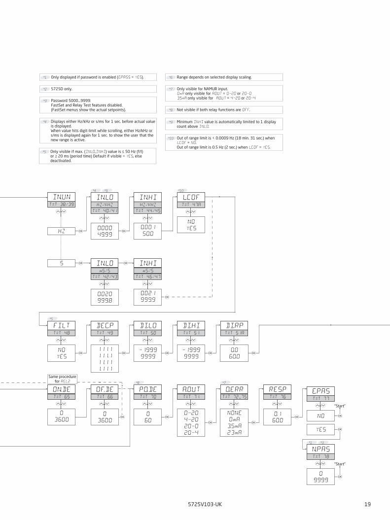
Routing diagram for 5725DIf no key is activated for 2 minutes, the display will return to the default state "Monitor" without saving configuration changes. 1 Increase value / choose next parameter2 Decrease value / choose previous parameter3 Save the chosen value and proceed to the next menuHold 3 Back to previous menu / return to default state "Monitor" without saving.
"Start" "Start"
"Monitor"
∼ 3 sec.
"Start"
Hold
"Start"
Same procedure for REL2
Fast setpoint adjustment and relay test1 Increase setpoint2 Decrease setpoint3 Save and exit the menu1 and 2 simultaneously = change relay
state.
12
12
12
12
IN.UNTT 38/39
IN.LOHZ/KHZ
0.000
49.99
IN.HIHZ/KHZ
0.001
50.0
L.COFTT 47A
NO
YESHZ 3 3
TT 40/41 TT 44/45
1212
IN.LOmS/S
0.020
999.8
IN.HImS/S
0.021
999.9
3
TT 42/43 TT 46/47
S 3
3
12
E.PASTT 77
NO
YES
12
N.PASTT 78
0
9999
3
3
3
*1
*4 *9 *10
12 12 12
ON.DETT 65
0
3600
PO.DETT 70
0
60
OF.DETT 66
0
3600
12 12 12
A.OUTTT 71
020
420
200
204
RESPTT 76
0.1
60.0
O.ERRTT 7275
NONE
0mA
3.5mA
23mA
3
3 3
*8
3
*3
*7
3
12
FILTTT 48
NO
YES
12 12 12
DEC.PTT 49
1111
111.1
11.11
1.111
DI.HITT 51
1999
9999
DI.LOTT 50
1999
99993 3 3
*5
12
DI.RPTT 51A
0.0
60.03 3
5725V103-UK 19
*1.4 Not visible if both relay functions are OFF.*8
*1 Only displayed if password is enabled (E.PASS = YES).
*5 Only visible if max. (IN.LO,IN.HI) value is ≤ 50 Hz (f/I) or ≥ 20 ms (period time) Default if visible = YES, else deactivated.
*10 Out of range limit is < 0.0009 Hz (18 min. 31 sec.) when L.COF = NO.Out of range limit is 0.5 Hz (2 sec.) when L.COF = YES.
*4 Displays either Hz/kHz or s/ms for 1 sec. before actual value is displayed.When value hits digit-limit while scrolling, either Hz/kHz or s/ms is displayed again for 1 sec. to show the user that the new range is active.
*9 Minimum IN.HI value is automatically limited to 1 display count above IN.LO.
"Start"
"Start"
Same procedure for REL2
*2 5725D only.
*3 Password 5000...9999:FastSet and Relay Test features disabled.(FastSet menus show the actual setpoints).
*6 Range depends on selected display scaling.
*7 Only visible for NAMUR input.0mA only visible for A.OUT = 020 or 2003.5mA only visible for A.OUT = 420 or 204

20 5725V103-UK
Help text overview
Top line Scrolling text TT NO
Language menu
UK UK - SELECT ENGLISH HELP TEXT 0
DK DK - VAELG DANSK HJAELPETEKST 1
DE DE - WAEHLE DEUTSCHEN HILFETEXT 2
FRFR - SELECTION TEXTE D’AIDE EN FRANCAIS
3
SE SE - VALJ SVENSK HJALPTEXT 4
ITIT - SELEZIONARE TESTI DI AIUTO ITALIANI
5
ESES - SELECCIONAR TEXTO DE AYUDA EN ESPANOL
6
CZ CZ - VYBER CESKOU NAPOVEDU 7
Error indication(when active, labels are flashing @ appr. 1 Hz)
SE.BR SENSOR WIRE BREAKAGE 8
IN.HI INPUT OVERRANGE 9
SE.SH SENSOR SHORT CIRCUIT 10
IN.LO INPUT UNDERRANGE 11
9.9.9.9. DISPLAY OVERRANGE 12
-1.9.9.9. DISPLAY UNDERRANGE 13
HW.ER HARDWARE ERROR 14
EE.EREEPROM ERROR - CHECK CONFIGURATION
15
RA.ER RAM MEMORY ERROR 16
NO.CA DEVICE NOT CALIBRATED 17
FastSet menu
F.SET
REL1 FAST SET MENU - SELECT RELAY 18
REL2 FAST SET MENU - SELECT RELAY 18
SETP (if fastset is enabled)
xxxx RELAY SETPOINT - PRESS OK TO SAVE 19
SETP (if fastset is disabled)
xxxx RELAY SETPOINT - READ ONLY 20
Configuration setup
PASS
xxxx SET CORRECT PASSWORD 21
IN
PNP PNP SENSOR INPUT 22
NPN NPN SENSOR INPUT 23
TTL TTL SENSOR INPUT 24
NAMU NAMUR SENSOR INPUT 25
S0 S0 SENSOR INPUT 26
TACH TACHO SENSOR INPUT 27
Top line Scrolling text TT NO
XmA SPECIAL CURRENT SENSOR INPUT 28
XV SPECIAL VOLTAGE SENSOR INPUT 29
TR.LO (when special voltage input is selected)
xxxx SET LOW TRIGGER LEVEL IN VOLT 30
TR.LO (when special current input is selected)
xxxx SET LOW TRIGGER LEVEL IN mA 31
TR.HI (when special voltage input is selected)
xxxx SET HIGH TRIGGER LEVEL IN VOLT 32
TR.HI (when special current input is selected)
xxxx SET HIGH TRIGGER LEVEL IN mA 33
Z.IN (when special voltage input is selected)
HI.Z SET INPUT RESISTANCE HIGH 34
PL.UP SET INPUT PULL UP 35
PL.DN SET INPUT PULL DOWN 36
S.SUP(not when NAMUR or S0 input is selected)
xxxx SET SENSOR SUPPLY VOLTAGE 37
IN.UN
HZ SET INPUT UNIT FOR FREQUENCY 38
S SET INPUT UNIT FOR PERIOD TIME 39
IN.LO
xxxx SET INPUT RANGE LOW IN HZ 40
xxxx SET INPUT RANGE LOW IN KHZ 41
xxxx SET INPUT RANGE LOW IN S 42
xxxx SET INPUT RANGE LOW IN mS 43
IN.HI
xxxx SET INPUT RANGE HIGH IN HZ 44
xxxx SET INPUT RANGE HIGH IN KHZ 45
xxxx SET INPUT RANGE HIGH IN S 46
xxxx SET INPUT RANGE HIGH IN mS 47
L.COF
NO ENABLE LOW CUT OFF 47A
YES ENABLE LOW CUT OFF 47A
FILT
NO ENABLE INPUT FILTER 48
YES ENABLE INPUT FILTER 48
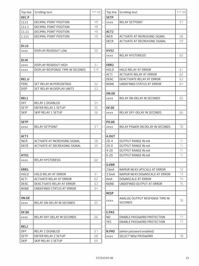
5725V103-UK 21
Top line Scrolling text TT NO
DEC.P
1111 DECIMAL POINT POSITION 49
111.1 DECIMAL POINT POSITION 49
11.11 DECIMAL POINT POSITION 49
1.111 DECIMAL POINT POSITION 49
DI.LO
xxxx DISPLAY READOUT LOW 50
DI.HI
xxxx DISPLAY READOUT HIGH 51
xxxx DISPLAY RESPONSE TIME IN SECONDS 51A
REL.U
PERC SET RELAY IN PERCENTAGE 52
DISP SET RELAY IN DISPLAY UNITS 53
REL1
OFF RELAY 1 DISABLED 54
SETP ENTER RELAY 1 SETUP 55
SKIP SKIP RELAY 1 SETUP 56
SETP
xxxx RELAY SETPOINT 57
ACT1
INCR ACTIVATE AT INCREASING SIGNAL 58
DECR ACTIVATE AT DECREASING SIGNAL 59
HYS1
xxxx RELAY HYSTERESIS 60
ERR1
HOLD HOLD RELAY AT ERROR 61
ACTI ACTIVATE RELAY AT ERROR 62
DEAC DEACTIVATE RELAY AT ERROR 63
NONE UNDEFINED STATUS AT ERROR 64
ON.DE
xxxx RELAY ON-DELAY IN SECONDS 65
OF.DE
xxxx RELAY OFF-DELAY IN SECONDS 66
REL2
OFF RELAY 2 DISABLED 67
SETP ENTER RELAY 2 SETUP 68
SKIP SKIP RELAY 2 SETUP 69
Top line Scrolling text TT NO
SETP
xxxx RELAY SETPOINT 57
ACT2
INCR ACTIVATE AT INCREASING SIGNAL 58
DECR ACTIVATE AT DECREASING SIGNAL 59
HYS2
xxxx RELAY HYSTERESIS 60
ERR2
HOLD HOLD RELAY AT ERROR 61
ACTI ACTIVATE RELAY AT ERROR 62
DEAC DEACTIVATE RELAY AT ERROR 63
NONE UNDEFINED STATUS AT ERROR 64
ON.DE
xxxx RELAY ON-DELAY IN SECONDS 65
OF.DE
xxxx RELAY OFF-DELAY IN SECONDS 66
PO.DE
xxxx RELAY POWER ON DELAY IN SECONDS 70
A.OUT
20-4 OUTPUT RANGE IN mA 71
20-0 OUTPUT RANGE IN mA 71
4-20 OUTPUT RANGE IN mA 71
0-20 OUTPUT RANGE IN mA 71
O.ERR
23mA NAMUR NE43 UPSCALE AT ERROR 72
3.5mA NAMUR NE43 DOWNSCALE AT ERROR 73
0mA DOWNSCALE AT ERROR 74
NONE UNDEFINED OUTPUT AT ERROR 75
RESP
xxxxANALOG OUTPUT RESPONSE TIME IN SECONDS
76
E.PAS
NO ENABLE PASSWORD PROTECTION 77
YES ENABLE PASSWORD PROTECTION 77
N.PAS (when password enabled)
xxxx SELECT NEW PASSWORD 78

100
90
80
70
60
50
40
30
20
10
0 10 20 30 40 50 60 70 80 90 100
t
Off N.O. Off N.O.On N.O.
On N.C. On N.C.Off N.C.
100
90
80
70
60
50
40
30
20
10
0 10 20 30 40 50 60 70 80 90 100
t
Off N.O. Off N.O.On N.O.
On N.C. On N.C.Off N.C.
22 5725V103-UK
Graphic depiction of the relay function setpoint
Relay unitsRelay units
Setpoint = 50
Hysteresis = 10
Setpoint = 50
Relay action: Increasing Relay action: Decreasing
Hysteresis = 10

5725V103-UK 23
Document historyThe following list provides notes concerning revisions of this document.
Rev. ID Date Notes103 1802 Relay data updated, graph with resistive loads
inserted Menu updated with display response time EU RO approval added

We are near you,all over the world
All our devices are backed by expert service and a 5-year warranty. With each product you purchase, you receive personal technical support and guidance, day-to-day delivery, repair without charge within the warranty period and easily accessible documentation.
We are headquartered in Denmark, and have offices and authorized partners the world over. We are a local
business with a global reach. This means that we are always nearby and know your local markets well. We are committed to your satisfaction and provide PERFORMANCE MADE SMARTER all around the world.
For more information on our warranty program, or to meet with a sales representative in your region, visit prelectronics.com.
Our trusted red boxes are supported wherever you are

PR electronics is the leading technology company specialized in making industrial process control safer, more reliable and more efficient. Since 1974, we have been dedicated to perfecting our core competence of innovating high precision technology with low power consumption. This dedication continues to set new standards for products communicating, monitoring and connecting our customers’ process measurement points to their process control systems.
Our innovative, patented technologies are derived from our extensive R&D facilities and from having a great understanding of our customers’ needs and processes. We are guided by principles of simplicity, focus, courage and excellence, enabling some of the world’s greatest companies to achieve PERFORMANCE MADE SMARTER.
Benefit today from PERFORMANCE MADE SMARTER
www.prelectronics.com