performance limitations of ieee 802.11 networks …kliazovich.org/papers/book_v3.2.pdf ·...
TRANSCRIPT

PERFORMANCE LIMITATIONS OF IEEE 802.11 NETWORKS ANDPOTENTIAL ENHANCEMENTS
FABRIZIO GRANELLI∗, DZMITRY KLIAZOVICH† , AND NELSON L. S. DA FONSECA‡
Abstract. The IEEE 802.11 standard is a significant milestone in the provisioning of networkconnectivity for mobile users. However, due to the time-variant characteristics of wireless links,interference from other devices and terminal mobility, 802.11-based WLANs suffer from performancedrawbacks in relation to wired networks. This chapter surveys the performance issues related tothroughput and delay in 802.11 networks and describes proposals to overcome such shortcomings.
Key words. IEEE 802.11, WLAN, Performance Evaluation, TCP over Wireless
1. Introduction. Wireless networks are becoming increasingly popular in tele-communications, especially for the provisioning of mobile access to wired networkservices. As a consequence, efforts have been devoted to the provisioning of reliabledata delivery for a wide variety of applications over different wireless infrastructures.In wireless network, regardless of the location, users can access services available towired-network users.
In this scenario, the IEEE 802.11 standards represent a significant milestone in theprovisioning of network connectivity for mobile users. However, the 802.11 mediumaccess control strategy and physical variability of the transmission medium leads tolimitations in terms of bandwidth, latency, information loss, and mobility. Moreover,the deployment of the Transmission Control Protocol (TCP) over IEEE 802.11 net-works is constrained by the low reliability of the channel, node mobility and longRound Trip Times (RTTs).
This chapter aims at providing a comprehensive analysis of the performance lim-itations and potential enhancements to 802.11 networks. Proposals to overcome suchlimitations are compared and their suitability for specific deployment scenarios ispresented.
The structure of this chapter is as following: Section 2 provides an overview of theIEEE 802.11 standards and its extensions. Section 3 surveys the performance issuesrelated to throughput and delay in 802.11 networks. Section 4 introduces existingproposals to overcome those problems. Sections 5 and 6 provide comparisons of thedifferent solutions. Finally, Section 7 draws some conclusions.
2. The 802.11 Standards. The IEEE 802.11 Wireless Local Area Network(WLAN) standards were first adopted in 1997 and revised in 1999 [1]. It aims at“providing wireless connectivity to automatic machinery, equipment or stations thatrequire rapid deployment, which may be portable or hand-held, or which may bemounted on moving vehicles within a local area” [1]. The IEEE 802.11 specificationprovides “wireless standards that specify an “over-the-air” interface between a wirelessclient and a base station or access point, as well as among wireless clients” [2].
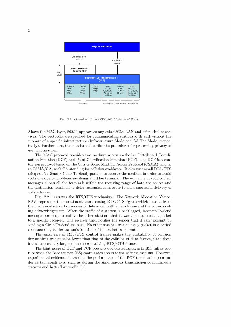
Figure 2.1 presents an overview of the IEEE 802.11 protocol stack. The standardsspecify the Medium Access Control (MAC) sublayer, the MAC management protocoland services as well as different physical layers (PHY). A key issue is transparency.
∗DIT - Univ. of Trento, Via Sommarive 14, I-38050, Trento (ITALY) E-mail:[email protected]†DIT - Univ. of Trento, Via Sommarive 14, I-38050, Trento (ITALY) E-mail:[email protected]‡Institute of Computing, State University of Campinas, Av. Albert Einstein 1251, Campinas, SP
(BRASIL) E-mail:[email protected]
1
2
Logical LinkControl
Contention-free service
Point Coordination Function ( PCF )
Distributed CoordinationFunction ( DCF )
Contention service
2.4- GHz FH - SS 1Mbps 2Mbps
2.4- GHz DS - SS 1Mbps 2Mbps
Infrared 1Mbps 2Mbps
5- GHz OFDM
6, 9, 12, 18, 24, 36, 48, 54 Mbps
2.4- GHz DS - SS 5.5 Mbps 11 Mbps
2.4- GHz DS - SS 6, 9, 12, 18, 24, 36, 48, 54 Mbps
MAC Layer
IEEE 802.11 IEEE 802.11a IEEE 802.11b IEEE 802.11g
Fig. 2.1. Overview of the IEEE 802.11 Protocol Stack.
Above the MAC layer, 802.11 appears as any other 802.x LAN and offers similar ser-vices. The protocols are specified for communicating stations with and without thesupport of a specific infrastructure (Infrastructure Mode and Ad Hoc Mode, respec-tively). Furthermore, the standards describe the procedures for preserving privacy ofuser information.
The MAC protocol provides two medium access methods: Distributed Coordi-nation Function (DCF) and Point Coordination Function (PCF). The DCF is a con-tention protocol based on the Carrier Sense Multiple Access Protocol (CSMA), knownas CSMA/CA, with CA standing for collision avoidance. It also uses small RTS/CTS(Request To Send / Clear To Send) packets to reserve the medium in order to avoidcollisions due to problems involving a hidden terminal. The exchange of such controlmessages allows all the terminals within the receiving range of both the source andthe destination terminals to defer transmission in order to allow successful delivery ofa data frame.
Fig. 2.2 illustrates the RTS/CTS mechanism. The Network Allocation Vector,NAV, represents the duration stations sensing RTS/CTS signals which have to leavethe medium idle to allow successful delivery of both a data frame and the correspond-ing acknowledgement. When the traffic of a station is backlogged, Request-To-Sendmessages are sent to notify the other stations that it wants to transmit a packetto a specific receiver. The receiver then notifies the sender that it can transmit bysending a Clear-To-Send message. No other stations transmit any packet in a periodcorresponding to the transmission time of the packet to be sent.
The small size of RTS/CTS control frames makes the probability of collisionduring their transmission lower than that of the collision of data frames, since theseframes are usually larger than those involving RTS/CTS frames.
The joint usage of DCF and PCF presents obvious advantages in BSS infrastruc-ture when the Base Station (BS) coordinates access to the wireless medium. However,experimental evidence shows that the performance of the PCF tends to be poor un-der certain conditions, such as during the simultaneous transmission of multimediastreams and best effort traffic [36].

3
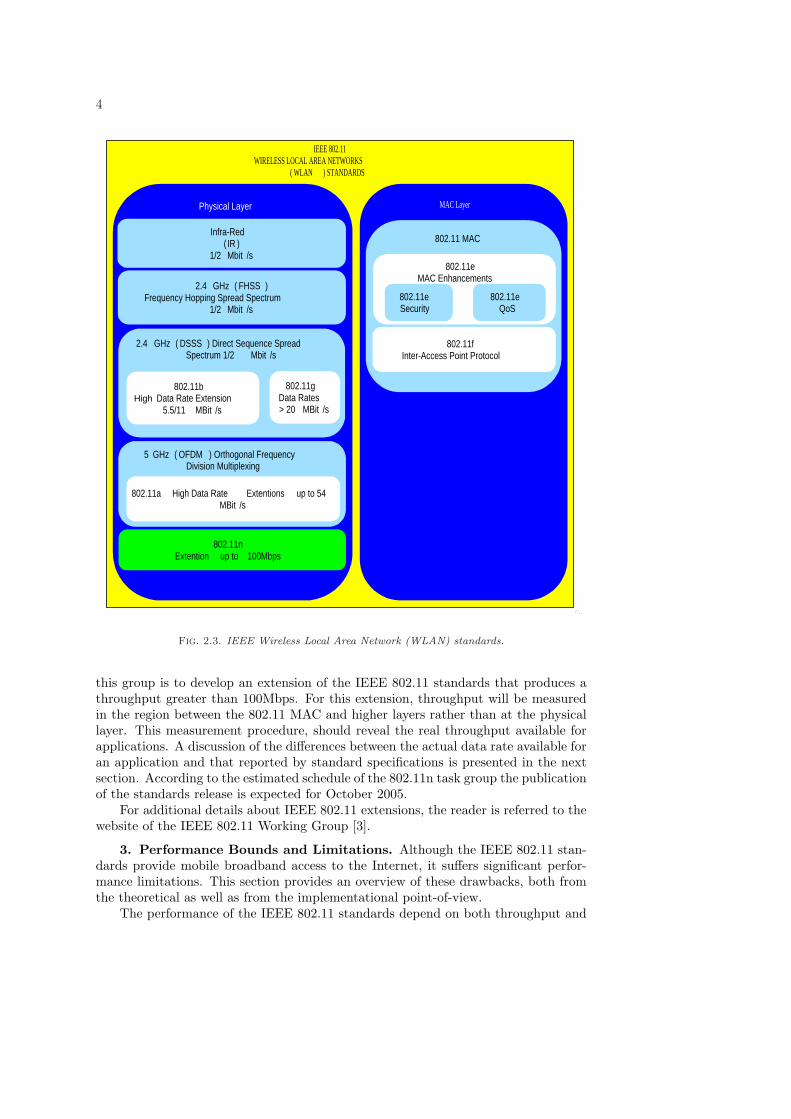
The hierarchy of the IEEE 802.11 standards for wireless local area networks ispresented in Fig. 2.3. Three physical layers are defined by these standards:
• Infra Red (IR), which supports bitrates of 1 or 2 Mbps;• Frequency Hopping Spread Spectrum (FHSS), operating at 2.4 GHz, which
supports bitrates of 1 or 2 Mbps;• Direct Sequence Spread Spectrum (DSSS), operating at 2.4 GHz, which sup-
ports bitrates 1 or 2 Mbps.
RTS
CTS
Frame
ACK
SIFS SIFS SIFS DIFS
Source Station
Destination Station
Station Close to Source
Station Close to Dest .
NAV
NAV
Fig. 2.2. 802.11 RTS/CTS mechanism.
In order to improve the wireless channel capacity, physical layer extensions to theoriginal IEEE 802.11 standard have been proposed.
The IEEE 802.11a extension adopts Orthogonal Frequency Division Multiplexing(OFDM) and works in the 5 GHz band to provide PHY data rates ranging from 6Mbps up to 54 Mbps.
The IEEE 802.11b extension, a High Data Rate Extension, is the most frequentlyused nowadays. It defines requirements for the extension of the DSSS at 2.4 GHz toachieve data rates of 5.5 Mbps and 11 Mbps. An important feature of this extensionis a rate shift mechanism which makes it possible for high data rate networks to slowthe rate down to 1 or 2 Mbps.
The IEEE 802.11g extension is similar to the 802.11a extension and specifies aphysical layer for wireless LANs in both 2.4 GHz and 5 GHz bands, with a maximumrate of 54 Mbps. Such a rate is achieved by using OFDM. This provides backwardcompatibility with the 802.11b extension, but is not compatible with the 802.11aextension. The drawbacks involve the complexities of implementation since the latterinvolves a less complex implementation. This backward compatibility in the 802.11gextension can be considered as a disadvantage, since an Access Point (AP) running atthe high data rate of 802.11g will switch down to the 802.11b rate upon the loggingof any 802.11b device, thus reducing the transmission rate of all other devices in acell [41].
The IEEE 802.11e protocol is an extension of the original MAC protocol aimed atproviding Quality of Service (QoS) support for a variety of multimedia services over802.11a, 802.11b and 802.11g physical layer specifications. In this extension, classesfor service differentiation are defined. It introduces certain enhancements of the basicfunctions of the MAC operation: Enhanced DCF (EDCA) and the Hybrid Coordi-nation Function (HCF), which operate in Contention and Contention Free periods,respectively.
The IEEE 802.11n task group was created at the end of 2003. The purpose of
4
IEEE 802.11 WIRELESS LOCAL AREA NETWORKS
( WLAN ) STANDARDS
MAC Layer Physical Layer
802.11 MAC
802.11e MAC Enhancements
802.11e QoS
802.11e Security
802.11f Inter-Access Point Protocol
Infra-Red ( IR )
1/2 Mbit /s
2.4 GHz ( FHSS ) Frequency Hopping Spread Spectrum
1/2 Mbit /s
2.4 GHz ( DSSS ) Direct Sequence Spread Spectrum 1/2 Mbit /s
802.11b Higb Data Rate Extension
5.5/11 MBit /s
802.11g Data Rates > 20 MBit /s
5 GHz ( OFDM ) Orthogonal Frequency Division Multiplexing
802.11a High Data Rate Extentions up to 54 MBit /s
802.11n Extention up to 100Mbps
High
Fig. 2.3. IEEE Wireless Local Area Network (WLAN) standards.
this group is to develop an extension of the IEEE 802.11 standards that produces athroughput greater than 100Mbps. For this extension, throughput will be measuredin the region between the 802.11 MAC and higher layers rather than at the physicallayer. This measurement procedure, should reveal the real throughput available forapplications. A discussion of the differences between the actual data rate available foran application and that reported by standard specifications is presented in the nextsection. According to the estimated schedule of the 802.11n task group the publicationof the standards release is expected for October 2005.
For additional details about IEEE 802.11 extensions, the reader is referred to thewebsite of the IEEE 802.11 Working Group [3].
3. Performance Bounds and Limitations. Although the IEEE 802.11 stan-dards provide mobile broadband access to the Internet, it suffers significant perfor-mance limitations. This section provides an overview of these drawbacks, both fromthe theoretical as well as from the implementational point-of-view.
The performance of the IEEE 802.11 standards depend on both throughput and
5
delay considerations when the CSMA/CA (with the RTS/CTS mechanism) is em-ployed. Actually, the main goal of the proposed mechanisms is the provision of bothhigh throughput on the wireless channel and low delay in packet delivery.
The most relevant issues are discussed next:
• Bandwidth – The IEEE 802.11 standards specify the rates available for datatransmission at the physical layer. The total link capacity is shared by allnodes which can operate within transmission range, including hidden termi-nals. Since collisions dramatically decrease the throughput, it is desirable tohave knowledge of the total available bandwidth. Thus, various predictivealgorithms have been proposed for that [33].Moreover, the IEEE 802.11 standards have certain theoretical limitations,due to the MAC policy, and these cannot be eliminated by simply raising thechannel capacity. In [4], these limitations, are identified as the ThroughputUpper Limit (TUL) and the Delay Lower Limit (DLL).
• Latency – Latency in a wireless medium is greater than in a wired one. Thefactors that influence latency are propagation delay, overhead added by bothphysical layer and link layer protocols and the retransmission policy imple-mented at the link layer.
• Channel losses – Wireless channels suffer from fading caused by interferencewith other sources. While the Bit Error Rate (BER) varies from 10−6 to 10−8
in wired channels, it varies from 10−3 to 10−1 in wireless channels [7]. Thetypical scheme used to recover from losses is the link layer ARQ (AutomaticResponse reQuest).
• Mobility – The most common network setting is the infrastructured BSS con-nected to a fixed network via a Base Station (BS). Handoff (Switching betweenthese BSs) require that all the information associated with user activities betransferred from BS to the next to prevent the termination of service providedto the mobile user.
• TCP – The problems that arise in the usage of TCP over wireless networksare due to their low reliability, as well as time-variant characteristics such asfading, shadowing, node mobility, hand-offs, limited available bandwidth andlarge RTTs. TCP performs poorly in such environments [10] [39] since theywere originally designed for use on wired networks, which are characterizedby stable links in which packet losses are mainly limited to congestion.
The IEEE 802.11 standards specify different rates for data transmission, rangingfrom 2 Mbps to 54 Mbps. However, a relatively large portion of the channel capacityis wasted due to the high overhead required for the transmission of data frames onthe wireless channel. Each message coming from the application layer needs to beencapsulated into lower layer Protocol Data Unit (PDU) in order to be transmittedon the physical layer. Figure 3.1 provides a graphical representation of the process ofpacket encapsulation when TCP is used. Most overhead due to packet encapsulationis related to the PLCP Preamble, which is necessary for the synchronization of thewireless receiver. This preamble, as well as the PLCP header, are transmitted at1 Mbps - regardless of the actual link speed. This makes it possible to operate atdifferent speeds, since the information about the rate of the remaining portion of thePPDU is included in the PLCP header. The PLCP preamble and header always take192 microseconds, regardless of the actual bitrate of the channel. An optional part ofthe 802.11 standards specifies the possibility of using a reduced, shorter preamble todecrease this overhead.

6
PPDU
PSDU
PLCP Preamble 18 byte
PLCP Header 6 byte
IEEE 802.11 Data Frame ( MPDU )
FCS 4 byte
Data (0 - 2312 byte) MAC
Header 30 byte
LLC 3 byte
TCP / IP Datagram ( MTU size)
IP Header 20 byte
TCP Header 20 byte
Data (MSS Size) 0-65495 byte
SNAP 5 byte
Fig. 3.1. Packet encapsulation in TCP over 802.11 networks.[11]Legend:FCS = Frame Check SequenceMSS = Maximum Segment SizeMTU = Maximum Transmission UnitSNAP = SubNetwork Access ProtocolLLC = Logical Link ControlMPDU = MAC Protocol Data UnitPLCP = Physical Layer Convergence ProtocolPSDU = PLCP Service Data Unit (SDU)PPDU = PLCP Protocol Data Unit (PLCP + MPDU)
Table 3.1Throughput Efficiency of 802.11 with long and short PLCP Preambles.
Link speed, Long Preamble (18 bytes) Short preamble (9 bytes)Mbps TCP Throughput, Efficiency, TCP Throughput, Efficiency,
Mbps % Mbps %1 0.75 74.9 0.77 76.92 1.41 70.7 1.49 74.3
5.5 3.38 61.5 3.83 69.611 5.32 48.4 6.52 59.3
Table 3.1 displays the maximum throughput obtained under the hypotheses ofnon-occurence of collisions, no fragmentation and no sending of RTS/CTS frames[11] (for a frame size of 1500 bytes, which is the maximum transfer unit (MTU)commonly allowed in Ethernet networks). A high percentage of the wireless linkcapacity is clearly wasted in transmitting supplementary information, which recudesthe bandwidth available for data transmission to a level well below the reportedcapacity. For the widely used IEEE 802.11b extension, which operates at a rate of11Mbps and employs a long PLCP preamble, the throughput is reduced to less thanhalf of the reported capacity. This value may be further decreased by exponentialbackoff and RTS/CTS mechanisms.
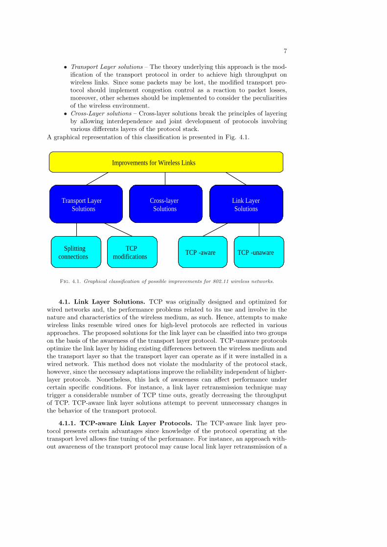
4. Available Enhancement Schemes. Various approaches have been pro-posed to optimize the performance of IEEE 802.11 wireless networks. These canbe broadly categorized into three groups:
• Link Layer solutions – The principle of this approach is to solve problemslocally, with the transport layer not being made aware of the characteristicsof the individual links. Such protocols attempt to hide losses in the wirelesslink to make it appear to be a highly reliable one. Link layer solutions requireno changes in existing transport layer protocols.
7
• Transport Layer solutions – The theory underlying this approach is the mod-ification of the transport protocol in order to achieve high throughput onwireless links. Since some packets may be lost, the modified transport pro-tocol should implement congestion control as a reaction to packet losses,moreover, other schemes should be implemented to consider the peculiaritiesof the wireless environment.
• Cross-Layer solutions – Cross-layer solutions break the principles of layeringby allowing interdependence and joint development of protocols involvingvarious differents layers of the protocol stack.
A graphical representation of this classification is presented in Fig. 4.1.
Improvements for Wireless Links
Transport Layer Solutions
Link Layer Solutions
Cross-layer Solutions
TCP -aware TCP -unaware TCP
modifications Splitting
connections
Fig. 4.1. Graphical classification of possible improvements for 802.11 wireless networks.
4.1. Link Layer Solutions. TCP was originally designed and optimized forwired networks and, the performance problems related to its use and involve in thenature and characteristics of the wireless medium, as such. Hence, attempts to makewireless links resemble wired ones for high-level protocols are reflected in variousapproaches. The proposed solutions for the link layer can be classified into two groupson the basis of the awareness of the transport layer protocol. TCP-unaware protocolsoptimize the link layer by hiding existing differences between the wireless medium andthe transport layer so that the transport layer can operate as if it were installed in awired network. This method does not violate the modularity of the protocol stack,however, since the necessary adaptations improve the reliability independent of higher-layer protocols. Nonetheless, this lack of awareness can affect performance undercertain specific conditions. For instance, a link layer retransmission technique maytrigger a considerable number of TCP time outs, greatly decreasing the throughputof TCP. TCP-aware link layer solutions attempt to prevent unnecessary changes inthe behavior of the transport protocol.
4.1.1. TCP-aware Link Layer Protocols. The TCP-aware link layer pro-tocol presents certain advantages since knowledge of the protocol operating at thetransport level allows fine tuning of the performance. For instance, an approach with-out awareness of the transport protocol may cause local link layer retransmission of a

8
packet, as well as duplicate acknowledgement, since retransmissions can be performedon both layers.
Snoop protocol. Snoop protocol [12] is used to handle connections in which most ofthe data are transferred from the Fixed Host (FH) to the Mobile Host (MH) (see Fig.4.2). The mobile node runs a snoop protocol while snoop agents are located at the basestation, which is the most common place for bridging the wired and wireless parts of anetwork. Snoop agents are implemented in the routing module of the protocol stack ofthe base station in order to allow inspection of the packet headers. These snoop agentsmaintain caches of TCP packets that have not yet been acknowledged by the MH. Incase of duplication of FH packets, the cache is updated without sending further packetsto the MH. Retransmission of cached packets is based on the reception of duplicateacknowledgements from the mobile node. Upon successful retransmission, duplicateacknowledgements are dropped at the Base Station (BS) to avoid the execution of theTCP fast retransmission mechanism.
A negative acknowledgement scheme has been added to improve theerror recovery mechanism in case most of the data are sent from the MH to the
wired network. In this way, the BS keeps track of all packets lost in any window andgenerates negative acknowledgements to the MH. These negative acknowledgementsare typically based on the Selective Acknowledgement (SACK) option of the TCP[22].
The main disadvantages of Snoop protocols [13] are:• Required changes in the base station protocol stack, demanding base station
resources;• No consideration of packet loss and delay during handoff;• Failure in Snoop operation for encrypted traffic when there is no access to
the packet header. The only possibility for handling encrypted traffic is tohave part of the TCP header unencrypted, which is not feasible according toexisting IP SEC standards specifications [37].
Ò
Ò
Fixed Host ( FH ) Base Station (BS) Mobile Host ( MH )
TCP
IP
LL
PHY
IP
LL
PHY PHY
Snoop Module TCP (SACK)
IP
LL
PHY
Fixed Network
Wireless Network
Fig. 4.2. Snoop protocol scenario.
WTCP. WTCP [6] performs local retransmission on the wireless link betweenthe base station and the mobile node without the need for modification of TCP forthe fixed nodes. WTCP running on a base station buffers all unacknowledged packetscoming from a fixed sender, maintaining its own flow control over the wireless link.

9
When an arriving segment is the next expected one, it is stored in the WTCP bufferalong with information about its arrival time. The sequence number of the nextexpected packet is then increased by the number of bytes included in the receivedsegment. When a duplicate packet is received, it is dropped, since it has either beendelivered to the wireless host or has already been buffered.
WTCP maintains the state of the information about the wireless part of theconnection, such as the transmission window, sequence number of the last acknowl-edgement received from mobile hosts, and sequence number of the last segment sentto a mobile host.
Inaccurate Round Trip Time (RTT) estimation at the sender can lead to unnec-essary retransmissions triggered by timeouts, since the sender writes the time stampof the generation of the segment and the receiver echoes it back without any modi-fication. If the segment is retransmitted, this RTT estimation may be affected. Toavoid this, in WTCP the timestamp of the packet is incremented by the length oftime the packet spent in the BS buffer. With this mechanism, the WTCP concealsthe existence of wireless link errors and the difference in round trip time (RTT) fromthe FH sender, thus avoiding timeouts caused by local retransmissions.
WTCP does not change the basic end-to-end TCP semantics, since acknowledge-ments to the fixed node are generated only after a successful packet delivery to themobile node.
4.1.2. TCP-unaware Link Layer Protocols. In early studies, enhanced linklayer performance was achieved by the implementation of error correction techniquessuch as forward error correction (FEC) or the implementation of various AutomaticRepeat ReQuest (ARQ) schemes for the retransmission of lost packets at the linklayer. The combined implementation of these two techniques is considered in theAIRMAIL protocol.
AIRMAIL. Asymmetric Reliable Mobile Access In Link Layer [14] is a protocoldesigned for both indoor and outdoor wireless networks. The combined usage of FECand local retransmissions provided by ARQ aims at obtaining enhanced end-to-endthroughput and latency by correcting errors in an unreliable wireless channel, as wellas on an end-to-end basis. The asymmetry in the design of the protocol reduces theprocessing load at the mobile node, since mobile terminals involve limited power andfewer computational resources than do base stations. The key idea in the asymmetricprotocol design approach consists of empowering the base station with a certain degreeof intelligence. The mobile terminal is required to combine several
acknowledgements into a single acknowledgement to conserve power. The BSis required to send periodic status messages, making the acknowledgement from themobile terminal event-driven. FEC implemented in AIRMAIL incorporates threelevels of channel coding with adaptive interaction. The coding overhead is adaptivelychanged so that bandwidth expansion from forward error correction is minimized.However, sending large packets of data through the wireless link to save power resultsin reduced error correction possibilities for the TCP [15].
TULIP. Transport Unaware Link Improvement Protocol [15] is designed for half-duplex radio links. The TULIP provides a reliable link for higher layer protocols.It is service-aware, i.e. it provides reliable service for TCP data traffic, althoughit is unreliable for UDP traffic. On the receiver side, this protocol buffers packets,passing only in-order packets to the upper-layer and thus preventing the recept ofduplicate acknowledgements (by the TCP). Another important feature implementedin the TULIP is the local link layer retransmission of lost packets, which effectively

10
prevent retransmissions over the entire path.Delayed Duplicate Acknowledgements (DDA). DDA involve an attempt to ap-
proximate the behavior of Snoop protocols. The BS implements a local link layerretransmission scheme for packets lost on wireless links. Such retransmissions aretriggered by link layer acknowledgements, rather than by the TCP-duplicated ac-knowledgements of the Snoop protocol scheme. As specified in [16], each TCP datapacket, as well as ACKs, are encapsulated into a single link layer data packet, withits successful reception acknowledged by the link layer ACK. This ACK contains thesequence number of the link layer packet received, which is independent of the TCPsequence number. Although it maintains sequence numbers at the link layer, DDAdoes not attempt in-order delivery of the TCP data packets. This is differente fromwhat happens with the Snoop protocol, for which duplicate acknowledgements arenot dropped immediately but rather delayed a certain length of time. At the sametime, the packet lost previously is retransmitted locally at the link layer. Upon thereception of an ACK, all delayed acknowledgements are dropped. If the retransmis-sion is not successful and the time for which duplicate acknowledgements are delayedhas expired, they will be released in the direction of the TCP sender to trigger re-transmission at the TCP level. DDA provides results equivalent to those producedby the Snoop protocol, although the technique does not perform well on slow wirelesslinks [16].
DAWL. Delayed-ACK Scheme on Wireless Link (DAWL) [17] [18] is a techniquedesigned for the enhancement of link layer performance. It modifies the standard IEEE802.11 MAC Stop & Wait ARQ by implementing the technique of native TCP delayedacknowledgement. The main idea is the lack of a need for immediate acknowledgementof packet receipt. DAWL assumes the existence of data in transit in the oppositedirection. The possibility of encapsulating acknowledgements into data packets atthe link level leads to the reduction of the traffic load in the wireless link. Moreover,DAWL implements a negative acknowledgement scheme for fast retransmission of lostpackets.
Like the Delayed-ACK option of TCP, DAWL provides certain advantages in thepresence of bi-directional traffic over wireless links. DAWL implementation requires aset of timers, which must be carefully tuned in order to optimize throughput, togetherwith delay insertion for a packet delivery. Although this approach provides advantagesfor operation on a single-hop wireless link, it is also problematic due to the:
• Difficulty in tuning timer values in the multi-hop environment;• The insertion of delay in packet acknowledgements;• Increased buffer requirements at all wireless node, and• Poor performance for links with high error rates.
4.2. Transport Layer Solutions. As mentioned above, TCP was originallydesigned for wired networks, where packet losses are caused mostly to network con-gestion, rather than errors resulting from noisy channels, handoffs and node mobility.A reduction in the congestion window is thus the TCP reaction to packet loss of anykind.
Despite the inadequacies of TCP implementation for wireless environments, changescan be avoided by adopting Link Layer solutions.
A reasonable number of solutions designed to achieve better performance throughthe modification of the TCP itself is available. These are logically divided into twogroups according to the technique they introduce: connection splitting approach andTCP modifications.

11
4.2.1. Connection Splitting Solutions. In this scheme, the end-to-end TCPconnection is divided into fixed and wireless parts, so that more degrees of freedomare available for the optimization of the TCP over both wired and wireless links.
The disadvantages of this solution mainly involve the attempt to perform trans-parent splitting (of the TCP) from the point of view of the TCP layer of the wiredhost. This leads to greater complexity in Base Station (BS) procedures, which is themost common and suitable place for splitting; the greater complexity involves notonly the handling of hand-offs but also, prevention of end-to-end semantics of theTCP connection and, also greater software overhead caused by the TCP part of thestack involved at the intermediate point.
I-TCP. Indirect-TCP (I-TCP)[19] was one of the firt proposals for using such aconnection-splitting approach. I-TCP is based on the indirect protocol model pro-posed in [20]. In this approach, (on the transport layer) the end-to-end connectionbetween an FH and a mobile network is split into two separate connections: onebetween the FH (with regular TCP) and the Mobility Support Router (MSR), com-monly the base station which serves the MH, and the other between the MSR andthe MH.
The creation of two separate connections makes it possible to optimize transmis-sion over the wireless link, concealing the loss recovery process on the wireless linkfrom the fixed sender by implementing a modified version of TCP. The flow (control)and congestion control mechanisms used by I-TCP allow faster reactions to wirelesslink problems such as communication interruption and mobility.
Whenever an MH moves to another cell (or BSS), all the information associatedwith the entire connection is handed over to the new MSR. The fixed host is completelyunaware of such indirection, although it maintains the end-to-end TCP connectionalive while the mobile node moves from one cell to another.
This I-TCP approach, however, presents certain drawbacks:• End-to-end TCP connection semantics cannot be preserved;• Base Station addition of increased overhead for each packet;• Decrease in complexity of the base station;• Additional overhead during hand-offs related to connection state transfer;• Not applicable to encrypted traffic.
METP. Mobile End Transport Protocol (METP) is a special transport protocoldesigned to use the connection-splitting approach on wireless links. The authors [21]propose the elimination of the TCP, as well as IP layer from the TCP/IP protocolstack of the wireless node, in order to reduce the overhead due to TCP and IP headersof the packet, as well as to their processing. The splitting point (BS) acts as a proxyfor the TCP connection, providing for conversion of the packets received from the fixednetwork. Assuming that the wireless link is the only wireless hop within the end-to-end connection, the METP approach shifts IP datagram reception from the MH tothe BS, which means that the packet passes through the IP and the Transport layer ofthe protocol stack of the BS. After the reception of a datagram, the BS then deliversthe data to the MH by using the METP protocol, which involves a reduced packetheader containing only minimal information (link source and destination addresses,port- and connection-related information).
METP provides reliable data delivery across the wireless link by introducing aspecial local retransmission scheme to link layer ARQ. It can also keep the overallTCP connection alive while dealing with handoffs. For this reason, all information,including states and sending and receiving windows, has to be handed over to the new
12
BS. The authors report a throughput enhancement of up to 37% over TCP Reno andof 23% over other approaches [21]. However, this approach also has drawbacks:
• End-to-end semantics are not preserved;• Great increase in complexity of the BS due to increased packet processing
through the BS protocol stack since it must be handled twice, once when itis received (by using the TCP/IP stack) at the fixed host and again when itis transmitted to the wireless part of the network by the METP;
• Additional overhead related to the transfer of large amount of informationduring handoffs.
4.2.2. TCP Modifications. TCP Modification invlolves a group of solutionswhich promote small changes on the behavior of TCP, such as the mechanics ofacknowledgement generation used by TCP. The modifications to the TCP make itunnecessary to modify the Base Station, thus avoiding overhead in packet delivery andthe increase in BS complexity. The major proposals in this framework are summarizedbelow.
Selective acknowledgements (SACK). TCP selective acknowledgements (SACKs)is one option [22] for the efficient handling of multiple losses within a single win-dow. The SACK acknowledgement algorithm enables the receiver to inform the TCPsender when packets are received out of order. The sender can then retransmit onlythose packets which have not reached the receiver. This technique is designed as animprovement of the standard cumulative ACK schemes in which retransmission istriggered by the reception of duplicate ACKs.
TCP using SACK provides a technique which performs better than standardTCP for multiple losses in a single window [10]. However, the window size must be“large enough” to take advantage of the SACK characteristics. The main drawbackof this selective acknowledgement is the modification of acknowledgement proceduresrequired at both sender and receiver.
TCP Santa Cruz. TCP Santa Cruz [23] employs the option field of the TCPheader for the implementation of new congestion control and error recovery strate-gies. The congestion control algorithm is based on relative delays, both that betweenpackets transmitted by a sender and that other between packets received at the re-ceiver. This information is calculated by the TCP Santa Cruz using timestamps addedto the packet at both ends, a technique originally presented in TCP Vegas [24]. Anincrease in the amount of information available about the TCP flow provides for moreaccurate RTT estimations at the sender side, while losses ACKs on their way backdo not influence the forward throughput. As an acknowledgement strategy, the TCPSanta Cruz can be used to SACK. This scheme leads to an improvement in perfor-mance in relation to both TCP Reno and TCP Vegas. The main drawback is theincreased complexity at the sender side.
Explicit Notification schemes. ECN (Explicit Congestion Notification) allows thesender to become aware of problems not related to congestion. Knowledge aboutwhy packets are lost on the wireless link can help senders, identify those instanceswhere congestion avoidance is not the proper reaction when losses have occurred.Different explicit notification schemes are available, as summarized in Table 4.1 [38]and described briefly below.
Explicit Bad State Notification (EBSN) [25] notifies the sender whenever a BS isunsuccessful in delivering a packet over the wireless network. To do this, it sends anEBSN message when a message is receveid, the TCP sender restarts its timer to avoidexecution of the slow start algorithm. This scheme requires minor modifications in

13
Table 4.1Summary of explicit loss notification schemes.
Name Mobile host is Generated by What it indicates Carried by PathEBSN destination BS Bad channel New signal To sourceELN source BS loss dupack To source
the TCP sender code.Explicit Loss Notification (ELN) [26] makes a sender aware of errors unrelated
to congestion while have occurred on the wireless link. The Base Station monitorsTCP packets in both directions. When a duplicate acknowledgement is received fromthe TCP receiver, the BS can encapsulate the ELN message by setting the ELN bitin the TCP acknowledgement header and forwarding it back to the sender. Thesender can then choose a type of reaction based on the type of loss. ELN doesnot, however, provide local retransmission, so no caching is necessary. However,the required checking of all TCP headers represents an increase in complexity andadditional overhead associated with each packet.
4.3. Cross-Layer Design. All of these approaches optimize a single parameterat a time, but when several different variables are to be considered they should betaken into account at the same time in order to achieve a truly optimal solution forthe adaptation of a TCP developed for a wired environment to a wireless scenario.
Such joint optimization can be included in the wide range of recently-proposedsolutions for optimizing wireless network design that are collectively labeled “Cross-Layer Design” [27] [28]. This approach breaks the ISO/OSI layering principles byallowing interdependence and joint design of protocols for passing from one layer toanother.
ILC-TCP. The most promising approach, Interlayer Collaboration Protocol (ILC-TCP) [29], was designed to improve the performance of the TCP in wireless environ-ments, involving long and frequent disconnections. The main modification is intro-duction of a State Manager (SM) in parallel with the protocol stack for gatheringinformation about TCP, IP and Link/Physical layers, if necessary, this informationcan be furnished upon the request of the TCP layer. Each layer (Link/Physical orIP) periodically reports its state to the SM. If conditions are not appropriate for theflow of the TCP, the SM suggests that the TCP sender stop sending packets. Whenconditions have improved, the TCP can proceed with regular data delivery.
This approach tries to optimize performance in a scenario in which mobile hostsact as TCP senders. It is an end-to-end approach which requires no changes in thefixed TCP receiver.
The authors [24] report an improvement up to 25% in throughput in relation tostandard TCP when disconnections and varied mobility patterns are present. How-ever, in the absence of problems, ILC-TCP offers no improvement in TCP operationover an end-to-end connection.
ATCP. In this approach, feedback between the network and the transport lay-ers is allowed as well as between the application and transport layers [30]. On theapplication level, information about priority is specified by the user and interpretedby the transport layer so that priorities can be established. This approach provides athroughput improvement of up to 40% over the Reno TCP.

14
LLE-TCP. Link-Layer ARQ Exploitation TCP (LLE-TCP) [31] introduces cross-layer collaboration, achieved by the utilization of link layer knowledge about successfuland unsuccessful packet delivery. LLE-TCP introduces an ARQ Snoop agent in theprotocol stack, and this agent keeps track of all TCP packets passing through thestack. For each TCP packet, the Snoop agent receives a message from the link layerindicating the result of delivery over the wireless medium. Whenever a packet reachesits destination, the ARQ Snoop agent at the sender side generates a TCP ACK packetfor the transport layer in order to acknowledge this delivery. On the receiver side, thecorresponding TCP acknowledgement is then dropped.
In summary, this technique provides the TCP layer with acknowledgements de-rived from local link layer acknowledgements, thus avoiding transmission of such ac-knowledgements over the wireless medium. Overhead can thus be reduced signifi-cantly.
The throughput achieved by this technique is strongly dependent on the size ofthe TCP data packets. One important advantage of this technique is that it does notlead to delay when packets are delivered over the wireless link.
The LLE-TCP does present certain drawbacks:• Increased complexity of the sender node required for the tracing of TCP
packets and generation of acknowledgement;• Difficulty in preserving TCP end-to-end semantics in multi-hop networks.
5. Comparisons. In this section, the available proposals are compared sincethese proposals act at different layers, there is no one proposal that outperforms theothers in all possible scenarios. The best way to compare them is to underline theirdifferences through a comparison of their characteristics. A brief summary of theexisting solutions and their advantages and disadvantages is presented in Table 5.1.
Certain features, however, are shared by all of the approaches belonging to thesame group. These characteristics and their limitations are described for each of thelayers.
Link Layer solutions. The main advantage of Link Layer solutions is the mainte-nance of end-to-end semantics, without modification of higher protocol layers. Thismakes it possible to leave untouched the existing implementations of the protocolstack in the various operating systems and limit the introduction of modifications tothe link layer.
Most of the approaches which operate at this level rely on some intermediate pointwithin the end-to-end connection for the introduction of performance improvements.For example, the Snoop protocol agent performs local retransmissions from a cache ofmonitored packets, and WTCP, although operating in a similar way introduces moreaccurate RTT estimations, thus preventing a reduction in TCP throughput. BothSnoop and WTCP must, however, have access to the header of TCP packets in orderto function, which reduces their usefullness value if traffic is encrypted. DDA solvesthis problem by introducing a local retransmission scheme based solely on informationtransferred at the link layer; by delaying duplicate acknowledgements, it prevents theTCP source from duplication of efforts in retransmissions, since packets are producedlocally at the link layer. The TCP-unaware protocols AIRMAIL and TULIP also relyon link layer retransmissions, but both also employ techniques for enhancement, theFEC for AIRMAIL and in-order delivery for TULIP.

15
Table 5.1Brief summary of existing solutions (advantages and disadvantages).
Name Advantages DisadvantagesLink Layer solutions
Snoop Designed for BSS infrastructure. Modification of base station stack.Performance of local retransmissions. No consideration of handoffs.No changes in TCP. Non-functional for encrypted traffic.
WTCP Performance of local retransmissions. Greatly increased BS complexity.Maintenance of more accurate RTT es-timation.
Mandatory maintenance state of infor-mation for TCP connections.Costly management of handoff.
AIRMAIL MH acknowledgements combined. TCP timeout caused atEvent-driven MS acknowledgement. high error rates.Power saving.Adaptive FEC implementation.
TULIP Provision of in-order delivery; local re-transmissions.
Can cause TCP timeout.
Useful on half-duplex radio links.DDA Provision of local retransmissions on
link layer.Difficulty in choosing delay value (d).
Dupacks delayed before dropping. Can cause TCP timeout.Performance poor on slow links.Functional for encrypted traffic.
DAWL ARQ enhancements with Delayed-ACK scheme.
Difficulty in tuning timers in multi-hopenvironment.
Performance good for one-hop, low er-ror rate link in presence of bi-
Increased delay of packet delivery ac-knowledgement.
directional traffic. Increased buffer requirements.Transport Layer solutions
I-TCP Useful in BSS infrastructure. End-to-end semantics not prevented.Connection splitting for faster reaction Increased overhead from BS stack.to loss over wireless link. Increased complexity of BS.
Overhead for state transfer duringhandoffs.Not applicable in asymmetric net-works.
METP Elimination of TCP and IP lay-ers, thus reducing header transmissionoverhead.
No end-to-end prevention.
Simplified headers on wireless link. Greatly increased BS complexity.Designed for BSS infrastructure. Handoff handling costly.
SACK Good Performance when window sizeis satisfactorily large.
Modification of TCP acknowledge-ment scheme required.
Selective TCP ACK scheme.TCP-SC Modification of congestion control and
error recovery mechanisms.Increased complexity of TCP sender.
Improved RTT calculation. TCP modificationEBSN Notification of TCP sender about
problemsMinor modifications of TCP.
on the wireless link to prevent slowstarts.
BS overhead.
ELN Notification of TCP sender about er-rors
Increased complexity of TCP.
occurring on wireless links. BS overhead.

16
Name Advantages DisadvantagesCross-Layer solutions
ILC-TCP Useful in wireless environments withfrequent and long disconnections.
Additional layer added to sender pro-tocol stack.
ATCP Prioritization of applications from up-per layers. Optimization of operationon basis of link state and RTO estima-tion from lower layers.
Modification of TCP, as well as otherlayers, for feedback.
LLE-TCP Utilization of link layer ACK informa-tion for local generation of TCP ACK
Increased sender complexity.
Not truly end-to-end.The maintenance of information related to the connection at intermediate nodes
brings an increased complexity of IR, especially when transport layer per flow supportis required (Snoop and WTCP), as well as a reduction in handoff performance whena large amount of information needs to be transferred to another IR to prevent thetermination of an end-to-end connection.
DAWL tries to simplify the system by introducing modifications only in the ARQscheme at the link layer and does not consider local retransmission at the IR. Thisdesign is advantageous in case of an IR crash. When this happens, all the informa-tion stored on the IR is lost, in the other schemes, and this would likely cause thetermination of the end-to-end connection.
Transport Layer solutions propose modifications to TCP in order to improve theperformance on wireless links. The modifications in the transport layer can be adoptedfor within the entire connection (SACK) or, separated by sender or receiver (EBSNand ELN). Moreover, the modification can focus directly on the wireless link, as inconnection-splitting solutions (I-TCP, METP).
The main requirement for the modification of the TCP for running on wirelesslinks is the allowance of the separation of losses due to congestion from those relatedto the nature of the wireless link (increased error rate, handoffs, etc.). The connectionsplitting solutions (I-TCP and METP) do not preserve the end-to-end semantics ofthe TCP while localizing the problem of the wireless link. At the same time, theyintroduce an increased complexity to the IR, as in the case of Link layer solutions.
The other approaches within this group preserve the end-to-end TCP semantics.SACK modifies the retransmission scheme of TCP in order to reduce unnecessaryretransmissions for non-continuous losses within a single TCP window, while TCP-SC modifies the TCP sender and receiver to improve the congestion control algorithmon the basis of relative delay information. Neither SACK nor TCP-SC require IRsupport and the increased complexity of the sender does not accumulate at a singlepoint, but is rather distributed among the several nodes of the network.
The explicit notification schemes EBSN and ELN require support from an IR inorder to provide information either about the state of the wireless link (EBSN) orabout the type of loss to the TCP sender (ELN). The crash of an IR does not have asignificant impact on the functionality of these solutions since there is no connection-related information stored at this point.
Cross-Layer solutions. All the solutions mentioned try to optimize the perfor-mance of IEEE 802.11 networks within a single link, without the support of the IR.
ILC-TCP provides the framework for TCP to obtain information about long andfrequent disconnections. From the lower layers of the protocol stack. More extensivefeedback is introduced by ATCP, in which the TCP obtains information not only from
17
the lower layers, but also from the application layer, depending of the level of priorityof the applications running above it. ATCP introduces a modified version of TCPmechanisms considering information gathered from lower layers, such as link stateand RTO estimation.
The differences between LLE-TCP, ILC-TCP and ATCP are mostly related tothe optimization approach adopted. None of these tries to preserve the E2E semanticsand leave the TCP unmodified. Increased performance is in fact obtained throughthe local generation of TCP acknowledgements based on packet delivery informationprovided by the link layer.
Table 5.2 provides a more detailed comparison of the existing protocols in relationto the following parameters:
• Protocol Layer: Solutions at the Link layer try to localize a problem and tothe optimization they perform from the Transport layer. Solutions presentedat the Transport layer, which are aware of the existence of wireless link,try to optimize TCP performance for conditions typical of the wireless link.Cross-layer solutions provide for joint optimization at both levels.
• End-to-end (E2E) semantics: This parameter identifies whether or not asolution preserves the end-to-end semantics of the TCP. Preservation meansthat the reception of an acknowledgement by the TCP sender provides for thenotification of successful data packet delivery to the TCP receiver throughoutthe entire end-to-end connection.
• TCP modification: This parameter indicates whether a solution requires mod-ifications to the TCP layer of the protocol stack. Since there are numerousimplementations of TCP in various operating systems from different vendors,a modification of TCP may require a huge effort. For this reason, solutionswhich include TCP modifications may find implementation in very limitednumber of cases, even if the improvement achieved is usually high.
• Intermediate Router (IR) support: The overwhelming majority of solutionsuse an intermediate point within the end-to-end connection for performanceoptimization, such as splitting the connection at that point, or using to notifyabout network conditions (ELN and EBSN). In BSS infrastructure, the BaseStation commonly plays the role of an IR. The rest of the parameters areconnected with the existence of an intermediate point along the transmissionpath.
• Retransmit at: The most commonly used technique for performance enhance-ment is the local retransmission of lost packets only on the wireless link,rather than throughout the entire end-to-end connection. The “Retransmitat” parameter indicates the point where retransmissions are performed, aswell as the protocol layer in which a solution handles retransmission.
• IR crash impact: When a solution relies on the IR, the crash of that interme-diate point can lead to the termination of the TCP connection. In some cases,there is no possibility of maintaining the data flow when state information islost.
Table 5.2 underlines the wide range of existing solutions, the differences in func-tionality implemented and their impact on network design. As can be seen, there isno single solution which will perform well in all scenarios.
6. Deployment scenario. Focusing on the different scenarios for deploymentof the schemes presented makes it possible to define different architectures involvingIEEE 802.11 wireless technology:
18
Table 5.2Comparison of existing solutions.
Scheme E2E TCP modification IR support Retransmit at IR crash impactLink Layer solutions
Snoop Present Absent TL/LL BS LimitedWTCP Present Absent TL/LL BS Limited
AIRMAIL Present Absent LL BS MinimalTULIP Present Absent LL BS MinimalDDA Present Absent LL BS Minimal
DAWL Present Absent None Sender NoneTransport Layer solutions
I-TCP Absent Present TL BS PresentMETP Absent Present TL BS PresentSACK Present Present None Sender None
TCP-SC Present Present None Sender NoneEBSN Present Present LL Sender NoneELN Present Present TL Sender None
Cross-Layer solutionsILC-TCP Present Present None Sender None
ATCP Present Present None Sender NoneLLE-TCP Absent Absent None Sender None
• single-hop wireless connections: This scenario involves transmission betweentwo mobile stations equipped with 802.11 wireless network cards, and by faris the simplest scenario.IEEE 802.11 networks rely mostly on link layer ARQ to provide the reliabledelivery of packets to transport protocols. If the link layer abandons thetransmission of a packet after all possible retransmissions, that packet willbe transmitted by the TCP. This does not, however, lead to much of anincrease in overhead, since there is only a single hop between the sender andthe receiver. DAWL takes advantage of improvements derived from the useof an ARQ scheme for relatively low channel error rates in the presence ofbi-directional traffic.The E2E solutions for the Transport layer, such as SACK and TCP-SC,improve the mechanism for TCP acknowledgement and congestion control,as well as recovery from error, and these will be reflected in performanceimprovements. All three solutions within the Cross-Layer area (ILC-TCP,ATCP and LLE-TCP) have been designed with this scenario in mind.
• multi-hop scenario: In this scenario, transmission occurs via multiple hops;there is no stationary infrastructure installed in multi-hop networks. Notethat the MAC protocol specified by the IEEE 802.11 standard does not per-form well in such an environment. Due to problems such as hidden nodes,exposed nodes and the unfairness of the exponential back off algorithm, thisprotocol “can not perform well in multi-hop networks” [32]. The analysisof existing solutions shows that the design of most proposals does not con-sider their operation in this scenario. In the best possible situation, only the

19
final hop of a multi-hop connection is taken into account. Transport layersolutions (I-TCP, METP and Explicit loss notification schemes) require thesupport of a IR within a connection. In a multi-hop scenario, there is no cen-tralized point for splitting (like BS), which makes the implementation of suchschemes difficult. The usage of Cross-Layer schemes is more realistic. Allmethods reviewed introduce modifications performed in the protocol stack ofthe sender node. In a multi-hop network, the LLE-TCP is introduced onlyduring the last hop [31].
• Wireless-cum-wired scenario: This is a more general and diffused scenariowhere a network is only partially wireless (802.11-based). The sender is lo-cated on the wired part of the network, which communicates with the mobilehost through the gateway (the BS, in BSS infrastructure). Almost all solu-tions consider this scenario in their design. Moreover, some of them (suchas Snoop, and WTCP) are especially designed to enhance performance inthis case. All solutions in the Transport and Cross-Layer approaches can beimplemented in a wireless-cum-wired scenario.
• WLAN-only scenario: In this scenario, all devices belong to the same WLAN,with a single Access Point. This scenario is similar to the Wireless-cum-wiredscenario described above, the sender is a mobile host which communicateswith a mobile receiver through an Access Point.
7. Conclusions. Wireless networks are becoming increasingly popular due tothe growing use of mobile access to network services. As a consequence, significantefforts have been devoted to providing reliable data delivery for a wide variety ofapplications over a variety of wireless infrastructures.
In this scenario, the IEEE 802.11 standard and its extensions have gained world-wide diffusion, providing reasonable performance with reduced infrastructure and de-ployment costs. However, performance bounds and limitations of 802.11 WLANsexist. This chapter has provided an overview of the various solutions available forcoping with these limitations.
¿From the analysis of existing improvements to the IEEE 802.11 standards, it isclear that there is no single best solution for all deployment scenarios.
Link layer solutions work on the wireless link without affecting higher-level pro-tocols, but they increase the complexity of the base station and require the modifica-tion of the MAC protocol on the wireless link (usually implemented in the hardware).Transport layer solutions aim at adapting the transport protocol to the character-istics of the wireless network, thus implying modification of the transport protocolin the protocol stack at both the sender and receiver ends. An alternate novel ap-proach is represented by cross-layer solutions, which establish interdependence andcollaboration between protocols in different layers of the stack.
REFERENCES
[1] IEEE Standard for Wireless LAN Medium Access Control (MAC) and Physical Layer (PHY)Specifications, ISO/IEC 8802-11::1999(E), August 1999.
[2] http://standards.ieee.org/wireless/overview.html#802.11[3] IEEE 802.11 Working Group Web Site, http://grouper.ieee.org/groups/802/11/[4] Y. Xiao and J. Rosdahl, Throughput and Delay Limits of IEEE 802.11, IEEE Communications
Letters, Vol. 6, No. 8, August 2002, pp. 355-357.[5] P. Chatzimisios, A.C. Boucouvalas, V. Vitsas, IEEE 802.11 Packet Delay - A Finite Retry
Limit Analysis, GLOBECOM 2003, pp. 950-654, 2003.
20
[6] K. Ratnam and I. Matta, WTCP: An efficient Mechanism for Improving TCP Performanceover Wireless Links, Proceedings of the Third IEEE Symposium on Computers and Com-munications, p. Athens, Greece, June 1998, p. 74-78.
[7] K. Pentikousis, TCP in Wired-Cum-Wireless, IEEE Communications Surveys, 2000.[8] J.B. Postel, Transmission Control Protocol, RFC 793, September 1981.[9] G.J. Miller, K. Thompson, and R. Wilder, Wide-area Internet traffic patterns and charac-
teristics, IEEE Network, November/December 1997, p. 10-23[10] K. Fall and S. Floyd, Simulation-based Comparisons of Tahoe, Reno, and SACK TCP,
Computer Communication Review 1996.[11] The Norwegian academic and research data network,
http://www.uninett.no/wlan/throughput.html[12] H. Belakrishnan, S. Seshan, E. Amir, and R. Katz, Improving TCP/IP Performance over
Wireless Networks, Proceedings of the 1st ACM International Conference on Mobile Com-puting and Networking (MOBICOM), Berkeley, CA, November 1995, pp. 2-11.
[13] H. Balakrishnan, V. Padmanabhan, S. Seshan, and R. Katz, A Comparison of Mecha-nisms for Improving TCP Performance over Wireless Links, IEEE/ACM Transactions onNetworking, December 1997, pp. 756-769.
[14] E. Ayangolu, S. Paul, T. LaPorta, K. Sabnani, and R. Gitlin, AIRMAIL: A Link LayerProtocol for Wireless Networks, Wireless Networks, vol. 1, 1995, pp. 47-60.
[15] C. Parsa and J.J. Garcia-Luna-Aceves, Improving TCP Performance over Wireless Net-works at the Link Layer, Wireless Communications and Networking Conference, IEEEWCNC, p. 1253 - 1257 vol. 3, September 1999.
[16] N.H. Vaidya, M. Mehta, C. Perkins, and G. Montenegro, Delayed Duplicate Acknowl-edgements: A TCP-unaware Approach to Improve Performance of TCP over Wireless,Technical Report 99-003, Computer Science Department, Texas A&M University, February1999.
[17] D. Kliazovich and F. Granelli, DAWL: A Delayed-ACK Scheme for MAC-Level Perfor-mance Enhancement of Wireless LANs, ACM/Kluwer Journal on Mobile Networking andApplications (MONET), August 2005.
[18] D. Kliazovich and F. Granelli, A Delayed-ACK Scheme for MAC-Level PerformanceEnhancement of Wireless LANs, 11th International Conference on Telecommunications(ICT’2004), Fortaleza (Brasil), August 2004.
[19] A. Bakre and B.R. Badrinath, I-TCP: Indirect TCP for mobile hosts, Distributed ComputingSystems, Proceedings of the 15-th International Conference, June 1995, pp. 196 - 143.
[20] A. Bakre, Design and Implementation of Indirect Protocols for Mobile Wireless Environments,Rutgers University, New Brunswick, NJ, USA, October 1996.
[21] K. Wang and S.K. Tripathi, Mobile-end transport protocol: an alternative to TCP/IP overwireless links, Seventeenth Annual Joint Conference of the IEEE Computer and Communi-cations Societies. Proceedings. IEEE , Vol. 3, April 1998, pp. 1046-1053.
[22] M. Mathis, J. Mahdavi, S. Floyd, and A. Romanow, TCP Selective Acknowledgment Op-tions, RFC 2018, April 1996.
[23] C. Parsa and J.J. Garcia-Luna-Aceves, Improving TCP Congestion Control over Internetswith Heterogeneous Transmission Media, in Proceedings of IEEE ICNP ’99, Toronto, Octo-ber 1999.
[24] L. S. Brakmo, S. W. O’Malley, and L. Peterson, TCP Vegas: New Techniques for Con-gestion Detection and Avoidance, In Proc. of ACM SIGCOMM ’94, London, October 1994,pp. 24-35.
[25] B.S. Bakshi, P. Krishna, N.H. Vaidya, and D.K. Pradhan, Improving performance of TCPover wireless networks, in Proc. of the 17th International Conference on Distributed Com-puting Systems ’97, Baltimore, Maryland, May 1997.
[26] H. Balakrishnan and R. Katz, Explicit Loss Notification and wireless web performance, inProc. IEEE Globecom Internet Mini-Conference, Sydney, Australia, Nov. 1998.
[27] Z.H. Haas, Design Methodologies for Adaptive and Multimedia Networks, Guest Editorial,IEEE Communications Magazine, Vol. 39, No. 11, pp. 106-107, November 2001.
[28] Q. Wang and M.A. Abu-Rgheff, Cross-layer signalling for next-generation wireless systems,IEEE Wireless Communications and Networking Conference (WCNC 2003), Vol. 2 , pp.1084-1089, March 2003.
[29] M. Chinta and S. Helal, ILC-TCP: An Interlayer Collaboration Protocol for TCP Perfor-mance Improvement in Mobile and Wireless Environments, Proceedings of the Trird IEEEWireless Communications and Networking Conference (WCNC), New Orleans, Louisiana,March 2003.
[30] V.T. Raisinghani, A.K. Singh, and S. Iyer, Improving TCP performance over mobile wire-
21
less environments using cross layer feedback, IEEE International Conference on PersonalWireless Communications, pp. 81-85, 15-17 Dec. 2002.
[31] D. Kliazovich and F. Granelli, A Cross-layer Scheme for TCP Performance Improvementin Wireless LANs, IEEE Global Communications Conference, GLOBECOM’04, Dallas, De-cember 2004.
[32] S. Xu and T. Saadawi, Does the IEEE 802.11 MAC Protocol Work Well in Multihop WirelessAd Hoc Networks?, IEEE Communi.Magazine, pp.130-137, June 2001.
[33] L. Cheng and I. Marsic, Lightweight Models for Prediction of Wireless Link Dynamics inWireless/Mobile Local Area Networks, in Proceedings of the IEEE 2002 Sarnoff Symposiumon Advances in Wired and Wireless Communications, pp. 98-101, NJ, USA, March 13, 2002.
[34] G. J. Miller, K. Thompson and R. Wilder, Wide-area Internet traffic patterns and charac-teristics, IEEE Network, November /December 1997, pp. 10-23.
[35] S. Choi and J. Prado, 802.11g CP: A Solution for IEEE 802.11g and 802.11b Inter-Working,in Proc. IEEE VTC’03-Spring, Jeju, Korea, April 2003.
[36] M.A. Visser and M. El Zarki, Voice and data transmission over an 802.11 wireless networkPersonal, Indoor and Mobile Radio Communications, PIMRC Vol. 2, September 1995 pp.648 - 652.
[37] S. Kent and R. Atkinson, Security Architecture for the Internet Protocol, RFC 2401, 1998.[38] T. Moors, TCP over Wireless, Lecture notes, http://subjects.ee.unsw.edu.au/tele4363/2003/,
2003.[39] D. Vardalis and V. Tsaoussidis, On the Efficiency and Fairness of Protocol Recovery Strate-
gies in Networks with Wireless Components, International Conference on Internet Comput-ing CSREA Press, Las Vegas, June 2001.
[40] S. Dawkins, G. Montenegro, M. Kojo, V. Magret, and N. Vaidya, End-to-end PerformanceImplications of Links with Errors, RFC 3155, IETF, August 2001.
[41] D. Robb, Although Newer, 802.11g Not Necessarily Better, Tutorial, http://www.wi-fiplanet.com/tutorials/article.php/3332691, 2004.