performance improvement of concentrated-flux type ipm pmsm
TRANSCRIPT

applied sciences
Article
Performance Improvement of Concentrated-Flux TypeIPM PMSM Motor with Flared-ShapeMagnet Arrangement
Keun-Young Yoon 1 and Soo-Whang Baek 2,*
1 Department of Electric Engineering, Honam University, 417 Eodeung-daero, Gwangsan-gu, Gwangju 62399,
Korea; [email protected] Department of Human Intelligence and Robot Engineering, Sangmyung University, Cheonan 31066, Korea
* Correspondence: [email protected]; Tel.: +82-041-550-5548
Received: 24 July 2020; Accepted: 18 August 2020; Published: 1 September 2020�����������������
Featured Application: We propose a new replaceable rotor shape of an interior permanent magnet
(IPM) motor to be used in electric water pump (EWP) systems of electric vehicles. The proposed
structure can reduce the torque ripple and improve efficiency characteristics of the basic IPM
permanent magnet synchronous motor (PMSM).
Abstract: This study demonstrates that the use of a flared-shape rotor structure in interior permanent
magnet (IPM) permanent magnet synchronous motor (PMSM) yields better performance than the
basic IPM PMSM motor, using a spoke structure with ferrite magnets. To concentrate the effective
magnetic flux, the proposed rotor structure is composed of a number of ferrite magnets, which are
inserted in a flared shape in the rotor core. This paper shows the comparison with the analysis results
of 2D finite element method (FEM), and it is shown that the proposed IPM PMSM motor can be
an effective substitute for the basic IPM PMSM motor, which requires low torque ripple and high
efficiency. In particular, the proposed flared IPM PMSM motor has lower pulsation of torque and
superior efficiency, as well as lower acoustic noise and vibration, compared to the basic IPM PMSM
motor. To verify the performance improvement of the proposed model, a prototype of the proposed
model was manufactured. It was experimentally confirmed that the proposed model has lower
torque ripple and higher efficiency than the basic model. Based on this performance improvement,
the proposed flared IPM PMSM motor is suitable for electric vehicles and home appliances.
Keywords: electric vehicles; electric water pump system; permanent magnet synchronous motor;
interior permanent motor; spoke rotor structure; flared-shape rotor structure; ferrite magnet
1. Introduction
The permanent magnet synchronous motor (PMSM) is widely used in the electric vehicle and
domestic appliance industries. The structure of the PMSM motor varies depending on the permanent
magnet arrangement in the rotor structure; among them, the interior permanent magnet (IPM) PMSM
motors made by inserting permanent magnets into rotors have advantages in applications requiring
high output power and high efficiency at load condition [1–4]. In particular, IPM type motors have
saliency depending on rotor shape. Because of, reluctance torque components can be obtained in
addition to magnetic torque components. Thus, the total torque of IPM PMSM motors is higher than
that of surface permanent magnet (SPM) PMSM motors, which comprise only magnet torque [5–9].
Several advanced studies have been conducted to improve motor properties through proposed
novel structure and topology for the motor, considering the advantages of this IPM type motor.
Appl. Sci. 2020, 10, 6061; doi:10.3390/app10176061 www.mdpi.com/journal/applsci

Appl. Sci. 2020, 10, 6061 2 of 15
In Reference [10], in order to increase the efficiency of the motor and achieve a wide operating
range at the same time, an optimal design for a concentrated flux type interior permanent magnet
(CFIPM) motor with a concentrated flux was proposed. In References [11,12], a concentrated flux
type ferrite magnet motor using a ferrite magnet was proposed to improve the efficiency of the motor.
Since the concentrated flux type permanent magnet motor has a high torque density, there are various
attempts to replace the performance of rare earth magnet motor with the concentrated flux type motor
using ferrite magnet. In References [13,14], a new structure was proposed for the concentrated flux
type synchronous motor (CFSM) to improve torque density and vibration characteristics. To increase
torque density, structures for improved motors were proposed using three different types of rotor
core structures. In References [15–18], studies were conducted to reduce torque ripple. When the
cogging torque characteristic of the motor is large, accuracy of position and speed control is reduced,
which can increase the torque ripple. Therefore, the effect of the main design parameters of the
motor for the reduction of cogging torque were accurately predicted and analyzed. In Reference [19],
a design method was explored to adopt the same topology with two rotors, with one inner coreless
stator, to improve the mechanical and electromagnetic performance of the motor. In Reference [20],
the magnetic field calculation and performance characteristics of a transverse flux machine (TFM) with
permanent magnet excitation were studied. The composition, magnetic flux distribution, the back
electro-motive force (EMF) and winding inductance characteristics of the TFM were analyzed, and the
effectiveness of a simplified computational model was verified. In Reference [21], a type of transverse
flux reluctance machine was studied. However, this design had the drawback of having a high
fundamental frequency and high torque ripple, which complicate the control of the motor. To address
this, a magnetic material study was conducted that could use a complex magnetic stator shape with a
3D magnetic flux path using a soft magnetic composite (SMC) in the magnetic circuit.
In this study, we will compare the characteristics of the basic IPM model (the spoke structure)
and the proposed flared type IPM model (the flared structure). In our previous study, two types
of concentrated flux type IPM motors with the flared-shape magnets arrangement were examined.
The flared type IPM model adopts a flared structure of C-shape ferrite magnets [22]. The proposed
flared-shape structure can increase the useful magnetic flux, so the flared type IPM motor is also a
form of the concentrated flux type IPM motor. The proposed flared-shape structure is optimized,
and the validity is verified experimentally [23]. The study proposes a flared type rotor structure for
replacing the basic spoke type IPM model, for performance enhancement. Additionally, the study aims
to determine possible alternatives and performance improvements through performance comparisons.
In particular, since the proposed model has advantages such as low torque ripple and reduction of
electromagnetic force causing noise vibration, it is necessary to apply the model in electric vehicles and
home appliances. In this study, the proposed model replaces the basic model used in the electric water
pump (EWP) system of electric vehicles. First, finite element method (FEM) analysis is used to compare
performance and determine whether it has improved. Subsequently, we compare the results of the
prototype analysis with those of the experiments. Finally, the improved performance and replacement
suitability of the proposed model were experimentally verified.
2. Structures of Basic Spoke Type IPM Model and Proposed Flared Type IPM Model
2.1. Electric Water Pump System
The engine cooling system maintains the temperature in the engine room at the required level.
If the temperature in the engine room is extremely high during vehicle operation, the component
strength of the engine cooling system decreases. Therefore, the engine cooling system is an important
device that keeps the temperature in the engine room at the desired level. The traditional engine
cooling method of a vehicle is a mechanical driving cooling technique that rotates a water pump pulley
using the driving force transmitted through a crankshaft. Recently, the electric and hybrid automobile

Appl. Sci. 2020, 10, 6061 3 of 15
market that requires high power and high responsiveness is expanding. In particular, the electric water
pump market driven by electric motors is also expanding.
An electric water pump system consists of three parts: cooling water that lowers the temperature
of the engine room, IPM motor that is responsible for the rotation of cooling water, and the controller.
IPM motors must satisfy high efficiency requirements because they use energy supplied from the
inside of the vehicle. In addition, since the engine cooling system is installed close to the engine room,
the torque ripple or excitation source of the IPM motor can cause noise vibration. Therefore, various
attempts have been made to improve the performance of EWP motors and to reduce torque ripple.
Figure 1 shows a 300 W EWP motor and the motor shape mounted inside. The IPM motor was
applied as a driving source.
Figure 1. Electric water pump system: (a) configuration and major components; (b) basic motor unit.
2.2. Basic Spoke Type IPM Model
Figure 2 shows the shape of the basic spoke type IPM model in which a permanent magnet is
magnetized in a concentrated flux structure (white mark). As shown in Figure 2, the basic spoke type
IPM model is applied with 8 poles and concentrated winding. The multi-polar structure of the IPM
model and the concentrated winding have a high output power density per unit volume and high
efficiency, so this model has been widely used in fields such as home appliances and electric vehicles.
Additionally, the spoke type motor is better at concentrating magnetic flux than other IPM motors.
Therefore, the magnetic flux can be utilized more efficiently and the output power density can be
increased. In order to prevent the problem of scattering during high-speed rotation, the rotor structure
is designed with an interior permanent magnet and composed of plastic resin, which is effective even
in high-speed rotation. Moreover, the basic spoke type IPM model uses ferrite magnets of grade 9BE,
which cost less than NdFeB magnets. Therefore, this model has a price advantage, and can be applied
to electric vehicles and household appliances. Table 1 shows the specification of the basic spoke type
IPM model.
Figure 2. Structure of basic spoke type interior permanent magnet (IPM) model: (a) full model;
(b) 1/4 model.

Appl. Sci. 2020, 10, 6061 4 of 15
Table 1. Specifications of the basic model and proposed model.
Item Unit Basic Model Proposed Model
Slot/Pole - 12/8 12/8Output power W 300 300
Speed rpm 4020 4020
Stator
Stack length mm 27.5 27.5Outer diameter mm 120.0 120.0
Material - 35PN270 35PN270
Rotor
Stack length mm 27.5 27.5Outer diameter mm 60 60
Material mm 35PN270 35PN270Air-gap mm 0.75 0.75
MagnetShape mm Bar-type C-type
Dimensions mm 16.5 × 7.4t 70deg × 3.4tMaterial - Ferrite (9BE) Ferrite (9BE)
WindingNumber of turns turns 30 30
Diameter mm 0.9 0.9Material - Copper Copper
2.3. Characteristics of the Basic Spoke Type Ferrite IPM Model
The performance analysis of motors can be divided into two main categories. First, the no-load
analysis confirms the winding specifications and the rotor geometry. Permanent magnet grade and
winding specifications are checked through the magnitude of the back EMF; the shapes of the rotor
and the stator are evaluated through the generated the back EMF waveform. Load analysis confirms
torque magnitude and ripple at the rated speed, and efficiency at the rated load point is confirmed
through copper and iron loss analysis. The noise vibration generation is compared relatively through
torque ripple and nodal force analysis.
The characteristics of the basic spoke type IPM model were investigated by conducting no-load
and load analyses on the basic spoke type IPM model. Figures 3 and 4 show the back EMF waveform
and the cogging torque waveform from the no-load analysis. The back EMF is generated by a sinusoidal
waveform, generating 23.65 Vrms per phase, and the THD (total harmonic distortion) of the back EMF
is 0.69%.
Figure 3. Back EMF of basic spoke type IPM model.
Appl. Sci. 2020, 10, 6061 5 of 15
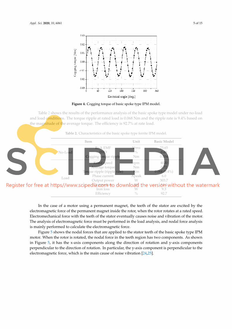
Figure 4. Cogging torque of basic spoke type IPM model.
Table 2 shows the results of the performance analysis of the basic spoke type model under no-load
and load conditions. The torque ripple at rated load is 0.068 Nm and the ripple rate is 9.4% based on
the magnitude of the average torque. The efficiency is 92.7% at rate load.
Table 2. Characteristics of the basic spoke type ferrite IPM model.
Item Unit Basic Model
No-Load
Back EMF Vrms 23.65THD % 0.69
Cogging torque ripple Nm 0.034
Load
Rated speed rpm 4020Average torque Nm 0.72
Torque ripple (ripple rate) Nm 0.068 (9.4%)Phase current Apeak 6.0Output power W 303.7
Copper loss W 14.4Iron loss W 9.3
Efficiency % 92.7
In the case of a motor using a permanent magnet, the teeth of the stator are excited by the
electromagnetic force of the permanent magnet inside the rotor, when the rotor rotates at a rated speed.
Electromechanical force with the teeth of the stator eventually causes noise and vibration of the motor.
The analysis of electromagnetic force must be performed in the load analysis, and nodal force analysis
is mainly performed to calculate the electromagnetic force.
Figure 5 shows the nodal forces that are applied to the stator teeth of the basic spoke type IPM
motor. When the rotor is rotated, the nodal force in the teeth region has two components. As shown
in Figure 5, it has the x-axis components along the direction of rotation and y-axis components
perpendicular to the direction of rotation. In particular, the y-axis component is perpendicular to the
electromagnetic force, which is the main cause of noise vibration [24,25].

Appl. Sci. 2020, 10, 6061 6 of 15
Figure 5. Nodal force components of the stator teeth.
Figure 6 shows a nodal force waveform applied to teeth under rated load conditions, and Table 3
shows a nodal force component along the x-axis and y-axis. As shown in Table 3, the y-axis directional
component of the nodal force is greater than the x-axis component.
Figure 6. Nodal force of the stator teeth (absolute component).
Table 3. Nodal force component in x-axis and y-axis directions.
Item Unit Basic Model
Nodal force (peak to peak)x-axis Nm 10.93y-axis Nm 121.24
2.4. Proposed Flared Ferrite IPM Model
In this paper, we propose a new model with a flat rotor shape to replace the existing model and
improve performance. The flared-shape structure has several C-shaped ferrite magnets arranged in a
flared shape in the rotor. The flared-shape structure of the ferrite magnets maximizes the utilization of
the ferrite magnets in the rotor core. Thus, the flared type structure can concentrate the magnetic flux,
which is caused by the arrangement of the magnets.
Figure 7 shows the structure of the proposed flared type IPM model, which has 12 slots /8 poles
and concentrated winding, and a permanent magnet is magnetized in a concentrated flux structure
(white mark). One pole consists of four C-shaped magnets, which are arranged in a flared shape.
Figure 8 shows the design process of IPM motors. In this paper, the permanent magnet weight of the
proposed model is set to be the same as that of the basic model, and then a flared magnet arrangement
structure is designed for the rotor.

Appl. Sci. 2020, 10, 6061 7 of 15
Figure 7. Structure of the proposed flared ferrite IPM model (1/4 model).
Figure 8. Design process of IPM motor.
Figure 9 shows the magnetization pattern of the proposed flared type IPM model. As shown in
Figure 9a,b, the proposed flared type IPM model can have two different patterns (parallel and radial
directions) and the magnetization pattern of the permanent magnet can determine the manufacturing
process of the permanent magnet. The magnetic flux density distribution inside the rotor resulting from
each magnetization pattern is different, as shown in Figure 9c,d, and the radial magnetization pattern
has the advantage that the magnetic flux is more concentrated than in the parallel magnetization
pattern. In this paper, characteristic analysis was performed on two patterns to determine the pattern
of magnetization. Finally, we applied the radial magnetization pattern to improve performance and
reduce torque ripple. Table 4 shows the magnet specifications of the conventional spoke model and the
proposed flared model. As shown in Table 4, the total use of permanent magnets in the initial model
and in the proposed model is the same. This means that there is no increase in material cost due to
permanent magnets. Although, the proposed flared type rotor structure is composed of a number of

Appl. Sci. 2020, 10, 6061 8 of 15
magnets compared to the basic IPM model so the assembly cost can increase in the manufacturing
process. However, it can be improved by using the assembly automation technology.
Figure 9. The magnetization direction of the proposed flared ferrite IPM model: (a) radial magnetization
pattern; (b) parallel magnetization pattern; (c) flux density of radial magnetization pattern; (d) flux
density of parallel magnetization pattern.
Table 4. Magnet specifications of the conventional spoke model and the proposed flared model.
Item Unit Basic Model Proposed Model
Material - YBM-9BE (Ferrite) YBM-9BE (Ferrite)Magnet shape - Bar-type C-typeDimensions mm 16.5 × 7.4t 70deg × 3.4t
Cross sectional area mm2 122.1 30.6Height (z-axis) mm 27.5 27.5Total quantity Ea 8 32Total weight g 134.3 134.3
3. Characteristics of Spoke Type IPM Model and Flared Type IPM Model
3.1. Characteristics at No-Load Condition
To examine the validity of the proposed model, the no-load analysis and the load analysis were
performed, and the performance improvement was confirmed by comparing the results. Figure 10
shows the back EMF waveform at the no-load condition. Compared to the basic spoke type IPM
model, the flared-shape structure of ferrite magnets has the advantage that magnetic flux is more
concentrated in the central part of the rotor core as a result of the arrangement of C-shaped ferrite
magnets. Therefore, the magnitude of back EMF of the proposed flared type IPM model in the no-load
condition increased by 4.96% compared to that of the basic spoke type IPM model.

Appl. Sci. 2020, 10, 6061 9 of 15
Figure 10. Characteristics of the back EMF waveform.
Figure 11 shows THD analysis of the back EMF waveforms. The THD of the back EMF is 1.47%
which is higher than in the basic spoke type IPM model (0.69%). In general, the limit of THD is under
3.0% in the electrical vehicle and domestic appliance industries.
Figure 11. Characteristics of total harmonic distortion (THD) of the back EMF waveforms.
Figure 12 shows the cogging torque waveforms at no-load. The proposed flared type IPM model
has increased effective magnetic flux due to the characteristic of magnetic flux concentration, and the
cogging torque ripple is 17% higher compared to the basic spoke type IPM model. Although cogging
torque ripple increased, the magnitude of the back EMF also increased; therefore, improved efficiency
is expected because the current is reduced at the rated load.
Figure 12. Characteristics of the cogging torque waveform.
Appl. Sci. 2020, 10, 6061 10 of 15
Table 5 shows the 2D FEM analysis results of the proposed flared type IPM model in comparison
with the basic spoke type IPM PMSM model.
Table 5. Comparison of the characteristics at no-load.
Item Unit Basic Model Proposed Model Rate
No-Load(4020 rpm)
Back EMF Vrms 23.65 24.82 N4.96%THD % 0.69 1.47 -
Cogging torque ripple Nm 0.034 0.040 N16.97%
3.2. Characteristics at Load Condition
The surfaced permanent magnet motor is a structure in which permanent magnets are attached
to the surface of the rotor. This structure has a constant magnetic resistance on the magnetic circuit,
so there is no difference in inductance between the d and q axes. Therefore, it is difficult to generate
additional reluctance torque, so the load analysis can be carried out by zero degrees of the advance
angle for the current source analysis.
However, the IPM motor has different magnetic resistance on the d and q axes. This is because
permanent magnets are inserted inside the rotor. The difference in magnetic resistance produces
additional reluctance torque. Therefore, the basic model and the proposed model should set an advance
angle by analyzing the changes in the torque according to the advance angle. Table 6 shows the average
torque of the basic model and proposed model according to the advance angle. As a result of the
torque analysis according to the advanced angle, both the basic model and the proposed model are
found to have maximum torque at 5 degrees.
Table 6. Characteristics of torque according to the advance angle.
Item Unit −15 −10 −5 0 5 10 15
Basic model (at 6.00 Apeak) Nm 0.680 0.698 0.711 0.719 0.722 0.718 0.710Proposed model (at 5.47 Apeak) Nm 0.667 0.688 0.704 0.714 0.719 0.718 0.711
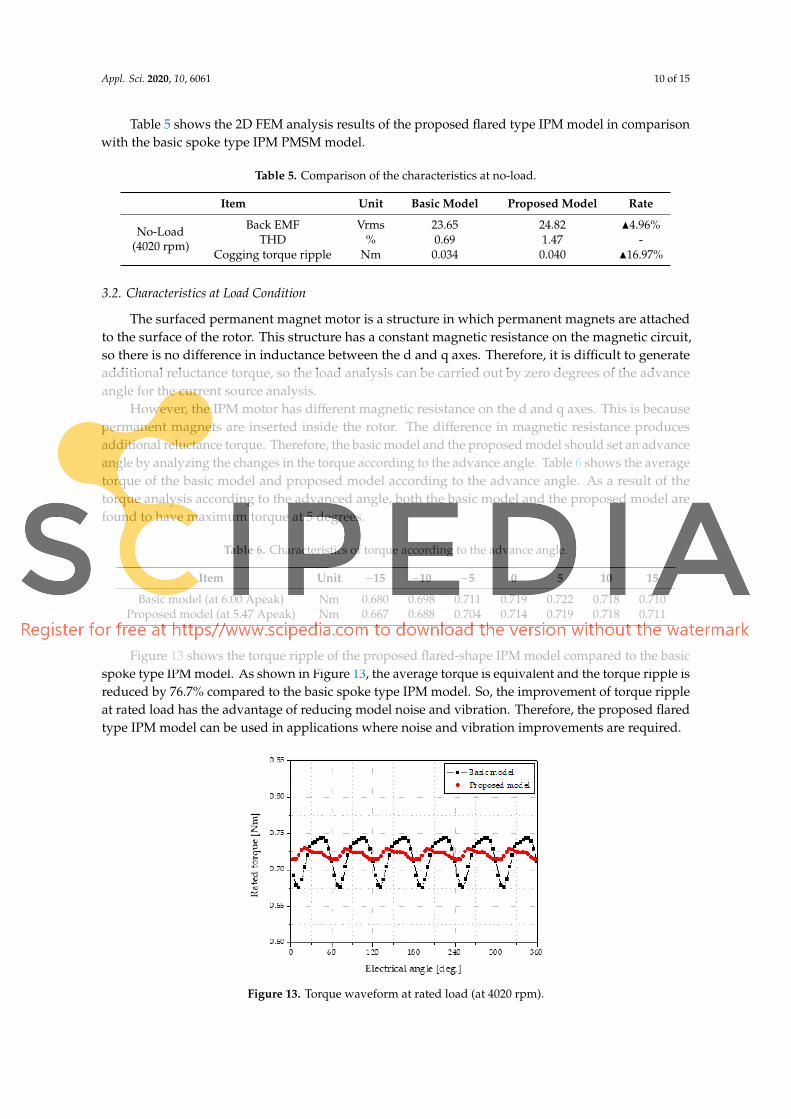
Figure 13 shows the torque ripple of the proposed flared-shape IPM model compared to the basic
spoke type IPM model. As shown in Figure 13, the average torque is equivalent and the torque ripple is
reduced by 76.7% compared to the basic spoke type IPM model. So, the improvement of torque ripple
at rated load has the advantage of reducing model noise and vibration. Therefore, the proposed flared
type IPM model can be used in applications where noise and vibration improvements are required.
Figure 13. Torque waveform at rated load (at 4020 rpm).

Appl. Sci. 2020, 10, 6061 11 of 15
Figure 14 shows the nodal force waveforms applied to stator teeth. When the nodal force by the
electromagnetic force is applied to the stator teeth as an exciting force, it causes noise and vibration at
operating point. In particular, the maximum change of the nodal force causes noise and vibration in
the stator teeth. Therefore, the nodal force applied to stator teeth should be minimized during the
initial design.
Figure 14. Nodal forces applied to stator teeth at the load condition.
Figure 15 shows the comparison of the nodal force of the proposed flared type IPM model
compared to the basic spoke type IPM model at the operating point; as shown in Table 7, the average
value of the nodal force of the proposed flared type IPM model is reduced by 3.0% compared to that of
the basic spoke type IPM model.
Figure 15. Comparison of the nodal force at the load condition.
Table 7. Comparison of nodal force of basic and proposed model.
Item Unit Basic Model Proposed Model Rate
Nodal force(peak to peak)
x-axis Nm 10.93 11.62 N6.31%y-axis Nm 121.24 117.60 H3.00%
Table 8 shows the 2D FEM analysis results of the proposed flared type IPM model in comparison
with the basic spoke type IPM model. As shown in Table 8, the proposed flared-shape ferrite IPM
model decreased copper loss by 16.3% and iron loss by 15.8%. The decrease in copper loss is due to
the decrease in rated current caused by the back EMF increase. Additionally, iron loss was relatively
reduced because the electrical steel usage of the rotors was reduced. Therefore, the efficiency of the

Appl. Sci. 2020, 10, 6061 12 of 15
proposed flared type IPM model in the rated load condition is 1.2% higher than that of the basic
spoke type IPM model. The torque ripple is also reduced by 76.6% compared to the basic spoke type
IPM model. Table 9 shows the comparison of iron loss by part, and it can be confirmed that most of
the iron loss reduction occurs in the rotors. Figure 16 shows a comparison of the flux density at the
load condition.
Table 8. Comparison of finite element method (FEM) analysis results.
Item Unit Basic Model Proposed Model Rate
Rated speed rpm 4020 4020 -Torque (average) Nm 0.72 0.72 -
Torque ripple Nm 0.068 (9.4%) 0.016 (2.2%) H76.6%Phase current Apeak 6.00 5.49 H8.5%
Current density Arms/mm2 9.43 8.63 H8.5%Output power W 303.7 302.5 -
Copper loss W 14.4 12.1 H16.3%Iron loss W 9.3 7.8 H15.8%
Efficiency % 92.7 93.8 N1.2%
Table 9. Comparison of iron loss by part.
Item Unit Basic Model Proposed Model Rate
Iron loss(Including Hysteresis)
Rotor W 1.50 0.59 H60.9%Stator W 6.46 5.97 H7.6%Teeth W 1.37 1.30 H5.1%Total W 9.33 7.86 H15.8%
Figure 16. Comparison of the flux density at the load condition: (a) flux density of proposed flared
type rotor; (b) flux density of basic spoke type rotor.
4. Experimental Verification
4.1. Prototype of Proposed model
To verify the performance improvement of the proposed flared IPM model, a real prototype was
produced and studied. Figure 17 shows the prototype for the proposed flared IPM model. Figure 17a
shows stator assembly, Figure 17b shows the rotor assembly, and Figure 17c shows the permanent
magnet arrangement inside the rotor assembly. Stator winding was produced by the concentrated
winding method. In order to prevent the deformation of the rotor during high-speed rotation, the rotor
was manufactured using 8 bolting points. The magnet used 9BE grade ferrite and required 32 magnets.

Appl. Sci. 2020, 10, 6061 13 of 15
Figure 17. Prototype of the proposed model; (a) stator assembly; (b) rotor assembly; (c) magnet
arrangement for flared shape.
4.2. Experimental Results
The load test was performed using the prototype. Figure 18 shows the torque waveform at rated
load, and Table 10 shows a comparison of the basic spoke type model and the prototype of the proposed
flared IPM model. As shown in Figure 18, the experimental results of the proposed flared IPM model
were similar compared to the analytical values. Additionally, torque ripple decreased by 66.2%, and
efficiency improved by 0.9%. This confirms the performance improvement of the proposed model.
Figure 18. Experimental characteristics at rated load test (at 4020 rpm) and enlarged torque
ripple waveform.
Table 10. Comparison of the basic model and the prototype model.
Item UnitBasic Model Proposed Model
RateAnalysis Analysis Experiment
Average torque Nm 0.72 0.72 0.72 -Torque ripple Nm 0.068 (9.4%) 0.016 (2.2%) 0.023 (3.2%) H66.2%Output power W 303.7 302.5 304.1 -
Efficiency % 92.7 93.8 93.6 N0.9%
5. Conclusions
In this paper, we proposed the flared type ferrite IPM model as an alternative to the basic spoke
type ferrite IPM model. As a result of the experimental results of the proposed flared IPM model,
the efficiency was increase by 0.9% and torque ripple was reduced by 66.2% compared to the basic
spoke type ferrite IPM PMSM motor. Therefore, the comparison using the results of FEM analysis
and the prototype experiment showed that the proposed flared IPM model is an effective substitute
for the basic spoke type IPM model requiring the same output. In particular, the proposed flared
type IPM model has lower torque ripple and higher efficiency than the basic spoke type IPM model.
The proposed flared type IPM model also has a low nodal force ripple, giving it an advantage for
acoustic noise and vibration. Through the analysis and experimental verification, we can confirm

Appl. Sci. 2020, 10, 6061 14 of 15
that the proposed flared type IPM model is an excellent alternative possibility for applications that
require low cost, high output, and low noise and vibration. Forward, we will conduct a noise vibration
experiment for the prototype to verify the improvement effect and optimize the proposed flared type
IPM model.
Author Contributions: Conceptualization, K.-Y.Y.; methodology, K.-Y.Y.; software, K.-Y.Y.; validation, K.-Y.Y. andS.-W.B.; writing—original draft preparation, K.-Y.Y.; writing—review and editing, K.-Y.Y.; and S.-W.B. fundingacquisition, S.-W.B. All authors have read and agreed to the published version of the manuscript.
Funding: This paper was supported by the National Research Foundation of Korea (NRF) Grant funded by theKorea government (MSIT) (no. 2017R1C1B5075525); this study was also supported by a 2017 research fund fromHonam University.
Conflicts of Interest: The authors declare no conflict of interest.
References
1. El-Refaie, A.; Jahns, T.; McCleer, P.; McKeever, J. Experimental verification of optimal flux weakening in
surface PM Machines using concentrated windings. IEEE Trans. Ind. Appl. 2006, 42, 443–453. [CrossRef]
2. Dutta, R.; Rahman, F. Design and Analysis of an Interior Permanent Magnet (IPM) Machine With Very Wide
Constant Power Operation Range. IEEE Trans. Energy Convers. 2008, 23, 25–33. [CrossRef]
3. Kim, S.-I.; Cho, J.; Park, S.; Park, T.; Lim, S. Characteristics Comparison of a Conventional and Modified
Spoke-Type Ferrite Magnet Motor for Traction Drives of Low-Speed Electric Vehicles. IEEE Trans. Ind. Appl.
2013, 49, 2516–2523. [CrossRef]
4. Kim, S.; Park, S.; Park, T.; Cho, J.; Kim, W.; Lim, S. Investigation and Experimental Verification of a Novel
Spoke-Type Ferrite-Magnet Model for Electric-Vehicle Traction Drive Applications. IEEE Trans. Ind. Electron.
2014, 61, 5763–5770.
5. Kim, H.-J.; Kim, D.-Y.; Hong, J.-P. Structure of Concentrated-Flux-Type Interior Permanent-Magnet
Synchronous Motors Using Ferrite Permanent Magnets. IEEE Trans. Magn. 2014, 50, 1–4. [CrossRef]
6. Ohnishi, T.; Takahashi, N. Optimal Design of Efficient IPM Model Using Finite Element Method. IEEE Trans.
Magn. 2000, 36, 3537–3539. [CrossRef]
7. Rahman, M.M.; Kim, K.-T.; Hur, J. Design and Optimization of Neodymium-Free SPOKE-Type Motor With
Segmented Wing-Shaped PM. IEEE Trans. Magn. 2014, 50, 865–868. [CrossRef]
8. Parasiliti, F.; Villaini, M.; Lucidi, S.; Rinaldi, F. Finite-Element-Based Multiobjective Design Optimization
Procedure of Interior Permanent Magnet Synchronous Model for Wide Constant-Power Region Operation.
IEEE Trans. Ind. Electron. 2012, 59, 2503–2514. [CrossRef]
9. Fang, L.; Jung, J.-W.; Hong, J.-P.; Lee, J.-H. Study on High-Efficiency Performance in Interior
Permanent-Magnet Synchronous Motor With Double-Layer PM Design. IEEE Trans. Magn. 2008, 44,
4393–4396. [CrossRef]
10. Lee, J.-H.; Kwon, B.-I. Optimal Rotor Shape Design of a Concentrated Flux IPM-Type Motor for Improving
Efficiency and Operation Range. IEEE Trans. Magn. 2013, 49, 2205–2208. [CrossRef]
11. Kim, J.-M.; Chai, S.-H.; Yoon, M.-H.; Hong, J.-P. Plastic Injection Molded Rotor of Concentrated Flux-Type
Ferrite Magnet Motor for Dual-Clutch Transmission. IEEE Trans. Magn. 2015, 51, 1–4. [CrossRef]
12. Kim, K.-S.; Park, M.-R.; Kim, H.-J.; Chai, S.-H.; Hong, J.-P. Estimation of Rotor Type Using Ferrite Magnet
Considering the Magnetization Process. IEEE Trans. Magn. 2015, 52, 1–4. [CrossRef]
13. Park, M.-R.; Jung, J.-W.; Kim, D.-Y.; Hong, J.-P.; Lim, M.-S. Design of High Torque Density Multi-Core
Concentrated Flux-Type Synchronous Motors Considering Vibration Characteristics. IEEE Trans. Ind. Appl.
2018, 55, 1351–1359. [CrossRef]
14. Park, J.-H.; Jung, K.-T.; Jung, Y.-H.; Lim, M.-S.; Yoon, M.-H.; Hong, J.-P.; Jung, J.-W. Design and Verification
for the Torque Improvement of a Concentrated Flux-Type Synchronous Motor for Automotive Applications.
IEEE Trans. Ind. Appl. 2019, 55, 3534–3543. [CrossRef]
15. Wang, Q.; Zhao, B.; Zhao, H.; Li, Y.; Zou, J. Optimal Design of Tubular Transverse Flux Motors With Low
Cogging Forces for Direct Drive Applications. IEEE Trans. Appl. Supercond. 2016, 26, 1–5. [CrossRef]
16. Bianchini, C.; Immovilli, F.; Lorenzani, E.; Bellini, A.; Davoli, M. Review of Design Solutions for Internal
Permanent-Magnet Machines Cogging Torque Reduction. IEEE Trans. Magn. 2012, 48, 2685–2693. [CrossRef]

Appl. Sci. 2020, 10, 6061 15 of 15
17. Bianchini, C.; Davoli, M.; Immovilli, F.; Lorenzani, E. Design optimization for torque ripple minimization
and poles cost reduction with hybrid permanent magnets. In Proceedings of the IECON 2014 - 40th Annual
Conference of the IEEE Industrial Electronics Society, Dallas, TX, USA, 29 October–1 November 2014; Institute
of Electrical and Electronics Engineers (IEEE): Piscataway, NJ, USA; Volume 40, pp. 483–489.
18. Yang, X.; Kou, B.; Luo, J.; Zhou, Y.; Xing, F. Torque Characteristic Analysis of a Transverse Flux Motor Using
a Combined-Type Stator Core. Appl. Sci. 2016, 6, 342. [CrossRef]
19. Kappatou, J.; Zalokostas, G.D.; Spyratos, D.A. 3-D FEM Analysis, Prototyping and Tests of an Axial Flux
Permanent-Magnet Wind Generator. Energies 2017, 10, 1269. [CrossRef]
20. Zou, J.; Zhao, M.; Wang, Q.; Zou, J.; Wu, G. Development and Analysis of Tubular Transverse Flux Machine
With Permanent-Magnet Excitation. IEEE Trans. Ind. Electron. 2011, 59, 2198–2207. [CrossRef]
21. Doering, J.; Steinborn, G.; Hofmann, W.; Doring, J. Torque, Power, Losses, and Heat Calculation of a
Transverse Flux Reluctance Machine With Soft Magnetic Composite Materials and Disk-Shaped Rotor.
IEEE Trans. Ind. Appl. 2014, 51, 1494–1504. [CrossRef]
22. Yoon, K.-Y.; Lee, J.-H.; Kwon, B.-I. Characteristics of new interior permanent magnet motor using flared-shape
arrangement of ferrite magnets. Int. J. Appl. Electromagn. Mech. 2016, 52, 591–597. [CrossRef]
23. Yoon, K.-Y.; Kwon, B.-I. Optimal Design of a New Interior Permanent Magnet Motor Using a Flared-Shape
Arrangement of Ferrite Magnets. IEEE Trans. Magn. 2016, 52, 1–4. [CrossRef]
24. Lin, C.; Fahimi, B. Prediction of Radial Vibration in Switched Reluctance Machines. IEEE Trans. Energy Convers.
2013, 28, 1072–1081. [CrossRef]
25. Callegaro, A.D.; Liang, J.; Jiang, J.W.; Bilgin, B.; Emadi, A. Radial Force Density Analysis of Switched
Reluctance Machines: The Source of Acoustic Noise. IEEE Trans. Transp. Electrif. 2018, 5, 93–106. [CrossRef]
© 2020 by the authors. Licensee MDPI, Basel, Switzerland. This article is an open access
article distributed under the terms and conditions of the Creative Commons Attribution
(CC BY) license (http://creativecommons.org/licenses/by/4.0/).