performance evaluation of on-chip sensor network …yao/docs/icgcs2010.pdfperformance evaluation of...
TRANSCRIPT

Performance Evaluation of On-Chip Sensor Network (SENoC) in MPSoC
Yao Wangl, Yu Wangl*, JiangXu2, HuazhongYangl lEE. Dept, TNList, Tsinghua University, Beijing, China
2Mobile Computing System Lab, Dept. of ECE Hong Kong University of Science and Technology, Hong Kong, China
Abstract--- As technology scaling, more processing units
(PUs) are integrated in multiprocessor system-on-chip
(MPSoC) to achieve higher performance. Due to the
higher variations resulted from reducing feature sizes
and the needs of lower power consumption, on-chip
monitoring of environmental information, such as
thermal, voltage, and frequency, is becoming increasingly important. To address this need, sensors are
integrated into network-on-chip (NoC) to perform
system monitoring. However, sensors which transfer
their data through NOC will compete with PUs for the
limited bandwidth resources, thus communication
between PUs will be delayed. To evaluate the sensors' overhead on the regular data traffic, we implement a VC
based NoC. The sensor data are transferred through
NoC together with the regular data. We study the
average delay of regular data and sensor data,
respectively. We compare the experimental results with
that of a NOC without sensors. The results show that the overhead of sensors is negligible, with a max delay
overhead of 0.800/0 when the traffic is not that heavy.
I. INTRODUCTION
Multiprocessor system-on-chip (MPSoC) design is becoming increasingly important to meet the fast growing performance demanded by complex applications. As a key aspect of MPSoC design, the interconnect architecture has a great influence on the overall performance of multi-corel many-core systems. In the past, the most frequently used on-chip interconnect architecture is the shared medium arbitrated bus, in which all processing units (PUs) share the same transmission medium. While the shared-bus architecture can provide simple topology and low cost, it also limits the number of PUs that can be connected to the bus. In the future when hundreds or even thousands of PUs are integrated onto a single chip, the bus architecture can no longer satisfy the performance needs of SoC. Hence, network-on-chip (NoC) was proposed to overcome the limitations of shared-bus architecture.
*Corresponding Author. This work is supported by National Natural Science Foundation of China(No.60870001), 863 project (No. 2009AAOIZ130), and TNList Cross-discipline Foundation. Dr. Jiang Xu's work is supported by RGC of the Hong Kong Special Administrative Region, China (Funding No. 621108) and HKUST PDF.
978-1-4244-6878-2/10/$26.00 ©2010 IEEE 323
A number of NoC architectures have been proposed such as the mesh architecture, the octagon architecture, the torus architecture, and the Butterfly Fat-Tree (BFT) architecture. Each of the NoC architectures may have its own advantages for some specific problems or tasks, but all of them are designed to achieve high throughput, low latency, low energy consumption, and small area, which are the desirable characteristics of MPSoC. However, these desired characteristics sometimes conflict with each other, so designers have to make trade-offs among them. Although NoC-based MPSoC significantly addresses the performance limitations of bus-based MPSoC, the challenges of MPSoC design still exist. On the one hand, more PUs are integrated onto a single chip as technology scaling. On the other hand, shrinking feature size results in higher variations which may cause reliability concerns. Therefore, it is crucial to use run-time monitoring information to control the system operation, guarantee the performance, and meet the reliability requirements.
For the purpose of run-time monitoring, sensors are integrated into NoC to monitor environmental information, such as the thermal, voltage, and frequency. Sensors are located in the distributed PUs, and sensor data are sent to one or more processing units which we can call "sensor manager" at a certain internal. The collected sensor data are then assessed in real time by the sensor manager. The results can be used by the system to know the status of PUs and initiate operations accordingly. For example, temperature sensors can report the run-time temperature of the PUs to sensor manager. If some PU is too hot, the sensor manager could send an order to this PU to perform dynamic voltage and frequency scaling (DVFS). Furthermore, the temperature information can also be utilized to achieve ''temperature-aware task scheduling".
On-chip sensor network (SENoC) [1] can keep the MPSoC aware of the status of each core, so the system can make wise decisions and maintain higher reliability. However, sensors which transfer their monitor data through NoC will compete with the PUs for the limited network bandwidth, thus communications between PUs might be delayed. Jia Zhao et al proposed a monitor subsystem called "MNOC" for SoC, which is a separate network-on-chip for monitor information transfer [2]. Although the sensor data will not interfere with the regular data in this way, a completely separate network-on-chip will lead to more area and higher design complexity, especially for the many-core
system. In this paper, we focus on the overhead of sensors on the NoC's performance. We implement a 4*4 mesh-like NoC which employs "Virtual Channel" (VC) in systemC. We study the overhead of sensor data by transferring sensor data together with regular data in several cases. We have recorded the average delays of sensor data and regular data, respectively. The results are compared with the original NoC without sensors.
The remainder of the paper is organized as follows. Section II introduces some related SENoC work. Section III describes our SENoC simulation platform, including the NoC architecture, the routers, and the switching methodologies, which serves as the basis of our performance evaluation. Section IV shows our simulation results and analysis. Section V concludes the paper.
II. RELATED WORK
Past SoC designs predominantly use shared-medium bus-based functional to integrate IP blocks [3]. There are mainly three types of commercial bus-based SoC interconnect specifications: ARM AMBA [4] bus, Wishbone [5], and IBM CoreConnect [6]. Sensors are incorporated into the bus-based SoC to perform system monitoring and control. Chan et al. proposed to use the power management bus (PMB) to exchange the sensor information between IP cores, which yields intricate control and optimal management of the system [7]. Velasumy et al. proposed a FPGA based SoC in which sensors are connected to the on-chip peripheral bus (OPB) to implement dynamic thermal management techniques [8]. The IBM Power6 architecture interconnects multiple sensors and actuators through a high-speed bus to perform voltage and thermal control [9].
Although effective for small numbers of cores, bus-based interconnect approaches are generally not scalable for increasing core counts [10]. Due to the fast growing demand for high performance, NoC replaces the bus interconnects in MPSoC design. Many different NoC architectures have been proposed in recent years. NoC overcomes the non-scalable limitation of bus architecture in MPSoC designs. However, with more PUs integrated onto a single chip and the higher variations brought by reducing feature size, it is necessary to deploy sensors into MPSoC to perform system monitoring and control. Wang et al. proposed a systematic approach, on-chip sensor network (SENoC), to collaboratively detect, report, and alleviate run-time threats in MPSoC, which achieves on average 26.12% performance improvement compared with the traditional methods [1]. Cioradas et al. proposed a monitoring service to offer run-time observability of NoC behavior and support application debugging [11]. While sensors bring some benefit to system monitoring and control in MPSoC, there may be some drawbacks since sensors will
324
occupy some network resources such as network bandwidth, hence decreasing the performance of MPSoC. In this paper, we mainly discuss the influence of sensors on the performance of NoC.
III. SENOC SIMULATION PLATFORM
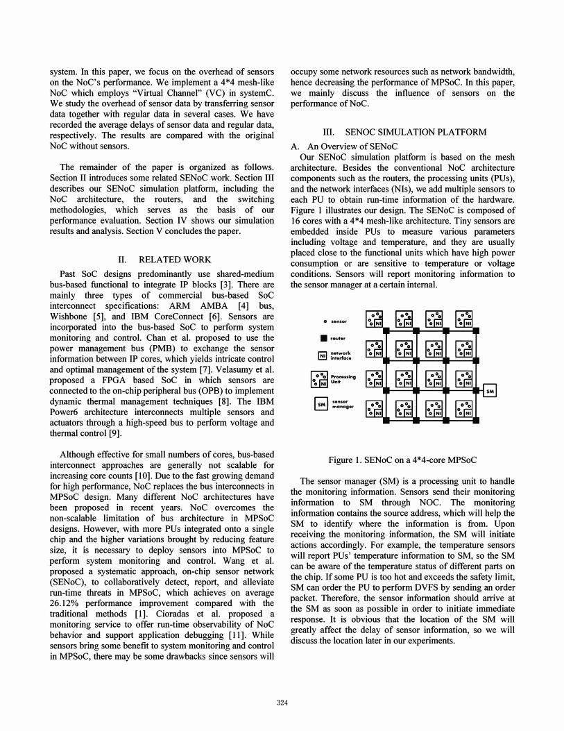
A. An Overview of SENoC Our SENoC simulation platform is based on the mesh
architecture. Besides the conventional NoC architecture components such as the routers, the processing units (PUs), and the network interfaces (NIs), we add multiple sensors to each PU to obtain run-time information of the hardware. Figure 1 illustrates our design. The SENoC is composed of 16 cores with a 4*4 mesh-like architecture. Tiny sensors are embedded inside PUs to measure various parameters including voltage and temperature, and they are usually placed close to the functional units which have high power consumption or are sensitive to temperature or voltage conditions. Sensors will report monitoring information to the sensor manager at a certain internal.
o sensor
• rout.r
1'::':1 network � interface
D .. nlOt' � manager
� o NI
10 0 r;ru o NI
loo� o NI
� °0 NI � °0 NI
� °0 NI � °0 HI
� 00 NI � 00 NI
Figure 1. SENoC on a 4*4-core MPSoC
SM
The sensor manager (SM) is a processing unit to handle the monitoring information. Sensors send their monitoring information to SM through NOC. The monitoring information contains the source address, which will help the SM to identify where the information is from. Upon receiving the monitoring information, the SM will initiate actions accordingly. For example, the temperature sensors will report PUs' temperature information to SM, so the SM can be aware of the temperature status of different parts on the chip. If some PU is too hot and exceeds the safety limit, SM can order the PU to perform DVFS by sending an order packet. Therefore, the sensor information should arrive at the SM as soon as possible in order to initiate immediate response. It is obvious that the location of the SM will greatly affect the delay of sensor information, so we will discuss the location later in our experiments.
B. Hardware Architecture Routers are the main components of our SENoC
platform. The block diagram of the router architecture is shown in Figure 2. The router architecture of SENoC is with little difference from that of a common NoC. The network interface (NI), however, has some changes due to the introduction of sensors. Our NI architecture is illustrated in Figure 3. The NI can pack the information of multiple sensors and multiplex the information with the regular data produced by the core. Besides, NI is responsible for unpacking the information from the router and delivering the information to the core.
Switching Fabric
Figure 2. The Router Architecture
p a c k
[��O�---l�P CORE k
u n
�--�-� � �---+-41111 c k
NETWORK INTERFACE
Figure 3. The Network Interface Architecture
C. Switching Methodologies Switching techniques determine how and when a router
delivers the message to its destination. In the wormhole switching, the fIrst flit, i.e. header flit, of a packet contains routing information. Header flit decoding enables the switches to establish the path and subsequent flits simply follow this path in a pipelined fashion. However, in this manner, messages must cross the channel in their entirety before the channel can be used by another message [3]. To
325
overcome the drawback, we introduce virtual channels (VC) [12] in the input and output ports to increase channel utility considerably. By introducing virtual channels, even though a flit belonging to one virtual channel is blocked, the flits of other virtual channels can still be transferred. As shown in Figure 2, there are four FIFO buffers in each input and output port, respectively. Each buffer represents a virtual channel, thus we have four virtual channels in one physical channel.
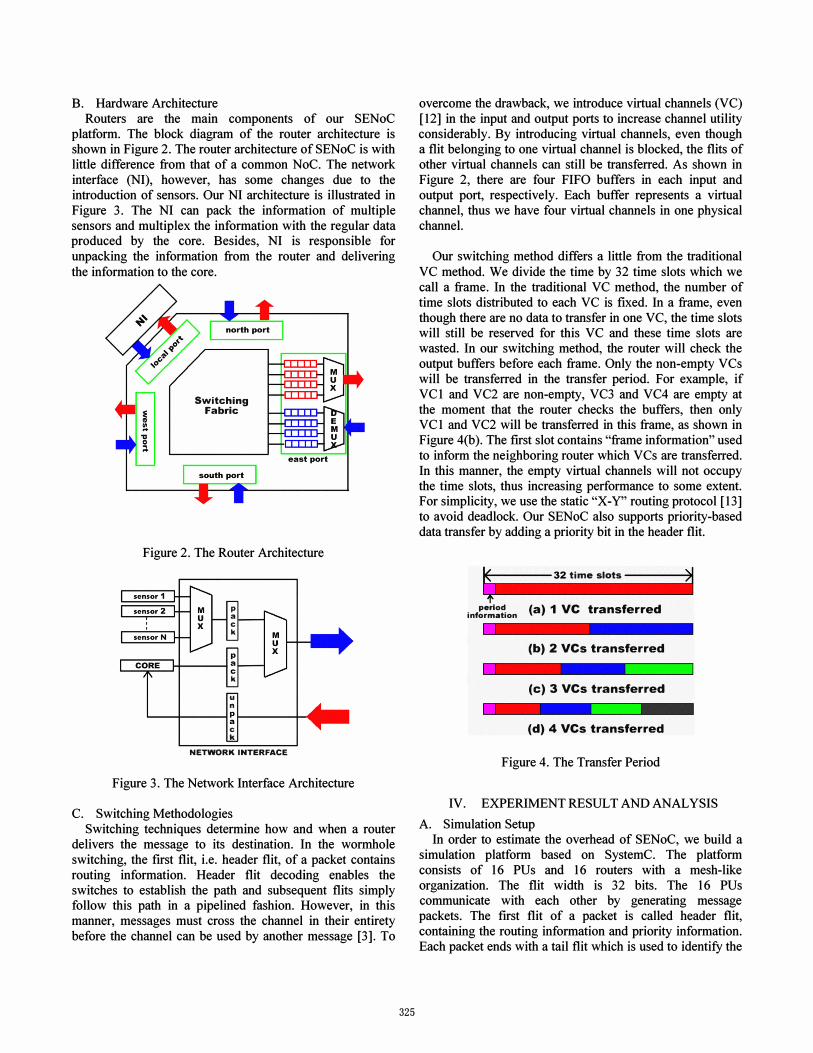
Our switching method differs a little from the traditional VC method. We divide the time by 32 time slots which we call a frame. In the traditional VC method, the number of time slots distributed to each VC is fIxed. In a frame, even though there are no data to transfer in one VC, the time slots will still be reserved for this VC and these time slots are wasted. In our switching method, the router will check the output buffers before each frame. Only the non-empty VCs will be transferred in the transfer period. For example, if VC1 and VC2 are non-empty, VC3 and VC4 are empty at the moment that the router checks the buffers, then only VC1 and VC2 will be transferred in this frame, as shown in Figure 4(b). The fIrst slot contains "frame information" used to inform the neighboring router which V Cs are transferred. In this manner, the empty virtual channels will not occupy the time slots, thus increasing performance to some extent. For simplicity, we use the static "X-Y" routing protocol [13] to avoid deadlock. Our SENoC also supports priority-based data transfer by adding a priority bit in the header flit.
�_----32 time slots ----H�
period information (a) 1 VC transferred
(b) 2 VCs transferred
(c) 3 VCs transferred
(d) 4 VCs transferred
Figure 4. The Transfer Period
IV. EXPERIMENT RESULT AND ANALYSIS
A. Simulation Setup In order to estimate the overhead of SENoC, we build a
simulation platform based on SystemC. The platform consists of 16 PUs and 16 routers with a mesh-like organization. The flit width is 32 bits. The 16 PUs communicate with each other by generating message packets. The fIrst flit of a packet is called header flit, containing the routing information and priority information. Each packet ends with a tail flit which is used to identify the

end of the message. The system operates at a constant frequency of 1 GHz. The data generated by the PU follow the Poisson distribution with a configurable average "A" which represents the average data rate. In our experiment, we classified the PUs into two categories, Master and Slave. Masters can send and receive packets while slaves can only receive message. The distribution of masters and slaves is shown in Figure 5. For uniformity, a master PU sends packets to the other 15 PUs randomly by equal possibility. The master PUs have the same traffic load, namely 1..=0.2. The depth of FIFO buffer is assumed to be 10.
���� -. -.
�
�
�
�
�
�
� �
� �
� �
M: Master S: Slave
SM
Figure 5. The Distribution of Masters & Slaves
Sensors are added into each PU to perform system monitoring and control. To accurately assess the overhead of SENoC, a realistic dispersal of sensors per core is needed. For DFS applications, previous work [14][15] have shown that for a core whose transistor count is around 68 million, 8 thermal sensors per core is appropriate. Numerous contemporary thermal sensors generate eight-bit data [16]. Therefore, we place 8 sensors in each PU and every sensor generates 8-bit data. There are totally 64-bit sensor data in each sample which we pack into two flits (32-bitlflit). With the header flit and the tail flit added, the sensor packet consists of 4 flits all together. The sensor data are sampled at a certain rate and then sent to SM. Typically, thermal values used for DVFS have been sampled every 10,000 cycles for a 3GHz core to achieve a thermal resolution of less than 0.1 degC [17]. Our system's operating frequency is IGHz, so the sampling rate is around one every 3,000 cycles. To evaluate the overhead of SENoC, we actually try faster sampling rates in our experiments.
We choose transport latency as the indication of the overhead. Transport latency is defined as the time (in clock cycles) that elapses from between the occurrence of a message header injection into the network at the source node and the occurrence of a tail flit reception at the destination node [18]. In order to reach the destination node from the source node, flits must travel through a path
326
consisting of several routers. Due to the different paths, each message may have different latencies. We use the average latency as the performance metric. Let N represents the total number of messages being transported, and let Li be the latency of each message. The average latency, Laverage can be calculated as follows,
L - LiLi Liarrive time[i]-Lisend time[i] average -
N N
B. Simulation results Our purpose is to evaluate the overhead of sensors on the
MPSoC's performance. We try different sampling rates of the sensor data, and record the average delays of regular data and sensor data, respectively. Besides, we also explore the influence of the SM's location on SENoC performance. The SM is placed at three locations, as shown in Figure 6 (A, B, C). To be rigorous, all the cases are simulated under the same test bench. Our simulation results are shown in TABLE 1. The results are measured in cycles.
GtlGtlGtlGtl -..
Gtl
Gtl
Gtl
Gtl
Gtl
Gtl
Gtl
Gtl
Gtl
Gtl .• r'B
Gtl
Gtl,.
Figure 6. The locations of SM
A
c
TABLE 1: The Average delay of regular data and sensor data in different scenarios
Location A (comer) B (center) C (edge)
Cycles Average Average Average Average Average Average Delay Delay Delay Delay Delay Delay Between of of of of of of Two Regular Sensor Regular Sensor Regular Sensor samples data data data data data data
00 98.86 N/A 98.86 N/A 98.86 N/A
200 99.65 130.80 98.79 104.87 99.19 113.64 500 98.98 120.24 99.32 105.48 98.47 106.78
1000 99.10 109.03 98.80 97.23 98.91 98.73
2000 98.99 101.83 98.87 98.03 98.89 93.70
From Table 1, we can see some interesting results. The
first row with the symbol "00" represents the original NoC without sensors. The average delay of the regular data for the original NoC is around 98.86 cycles. After adding sensors, the average delay of the regular data, which is between 99.65 and 98.47, doesn't change much. In some cases, the regular data even travel faster than that of the original NoC. This results from our switching methodology.

For example, in the original NoC, the router checks the buffers before the transfer period and fmds VCI empty, thus VCI will not be transferred in this transfer period. Even though a regular packet arrived at VCI after the check, the packet has to wait for the next transfer period. However, after adding sensors into NoC, VCI may be non-empty because of the sensor data, hence VC I can be transferred in the transfer period. Then the regular data arriving at VC I are transferred immediately. In this way, the average delay of regular data will decrease.
Although the average delay of regular data has changed, the max delay is only about 99.65, which is 0.80% more than 98.86 (the average delay of the original NoC). What's more, we have chosen faster sampling rates than reality. From this point, we can conclude that the overhead of using NoC to transfer sensor data is negligible. It is not necessary to build another network to transfer only sensor data, when the traffic is not that heavy. From each column of the simulation results, we can draw another conclusion that the average delay of sensor data will decrease if the sampling rates decrease. The best location of the SM is affected by the distribution of the traffic flow. In our experiments, we assume the traffic distribution is uniform. If we compare the average delay of sensor data for the three locations (center, edge, comer) of SM, we can conclude that it is best to put the SM in the center of the mesh, which leads to least average delay of sensor data.
V. CONCLUSIONS
This paper evaluates the overhead of SENoC on the performance of NoC. A 4*4 mesh SENoC simulation platform is built. We apply several sampling rates to the SENoC platform and record the average delay of regular data and sensor data. The experimental results show that the overhead of SENoC is negligible with only 0.80% delay overhead. We have tried three different locations of the SM to fmd the best location of SM in a mesh-like architecture. According to the results, it is best to place the SM in the center to achieve the least average delay of sensor data under the uniform traffic flow. Our future work will focus on the scalability of our SENoC simulation platform since the number of cores will increase to hundreds or even thousands. We will also study the best location of the SM under non-uniform traffic distribution.
REFERENCES
[1] Yu Wang, Jiang Xu, Shengxi Huang, Weichen Liu, HUazhong Yang, "A Case Study of On-Chip Sensor Network in Multiprocessor System-on-chip," in CASES 2009 [2] S. Madduri, R. Vadlamani, W. Burleson, R. Tessier, "A Monitor Interconnect and Support subsystem for Multicore
327
Processors," in the Proceedings of the IEEE/ACM Design Antomation and Test in Europe Conference, Nice, France, April 2009. [3] Partha Pratim Pande, C. Grecu, M. Jones, A. Ivanov, R. Saleh, "Performance Evaluation and Design Trade-offs for network-on-chip interconnect architectures," IEEE transactions on Computers, 2005 [4] AMBA Bus specification, http://www.arm.com. 1999 [5] Wishbone Service Center, http://www.silicore.net/wishbone.htm. 2004 [6] CoreConnect Specification,
http://www3.ibm.com/chips/products/coreconnect/. 1999 [7] C. Chan, Y. Chang, H. Ho, and H. Chiueh, "A thermal-aware power management soft-ip for platform-based soc designs", System-on-Chip, 2004. Proceedings. 2004 International Symposium on, pp. 181-184, Nov. 2004 [8] S. Velusamy, W. Huang, J. Lach, M. Stan and K. Skadron, "Monitoring Temperature in FPGA based SoCs", in the Proceedings of IEEE International Conference on Computer Design, pp. 634-637, Oct. 2005 [9] M. Floyd, S. Ghiasi, T. Keller, K. Rajamani, F. Rawson, J. Rubio and M. Ware, "System Power Management Support in the IBM Power6 Microprocessor," in IBM Journal of Research and Development, vo1.51, pp. 733-746, Nov 2007 [10] T. Bjerregaard and S. Mahadevan, "A Survey of Research and Practices of Network-on-Chip," in ACM Computing Survey, vol.38, no.1, Mar. 2006 (11) C. Ciordas, T. Basten, A. Radulescu, K. Goossens, and J. Meerbergen. An event-based network-on-chip monitoring service. In Proc. of the 9th IEEE International High-Level Design Validation and Test Workshop, pages 149-154, 2004. [12] J. Duato, S. Yalamanchili, and L. Ni, Interconnection
networks- An Engineering Approach. Morgan Kaufinann, 2002 [13] Jie Wu, Danji Wang, "Fault-Tolerant and Deadlock-Free Routing in 2-D Meshes Using Rectilinear-Monotone Polygonal Fault Blocks," proceedings. International conference on Parallel Processing, 2002 [14] R. Mukherjee and S. Memik, "Systematic temperature sensor allocation and placement for microprocessors", in the Proceedings of the 43rd ACM IEEE Design Automation Conference, pp. 542-547, July 2006 [15] S. Memik, R. Mukherjee, M. Ni and J. Long, "Optimizing Thermal Sensor Allocation for Microprocessors", in IEEE Transactions on Computer-Aided Design of Integrated Circuits and Systems, vol. 27, issue 3, pp. 516-527, 2008 [16] B. Datta and W. Burleson, "Low-Power, Process-Variation Tolerant On-Chip Thermal Monitoring using Track and Hold Based Thermal Sensors", in the Proceedings of ACM Great Lakes Symposium on VLSI, pp. 145-148, 2009 [17] K. Skadron, M. Stan, K. Sankaranarayanan, W. Huang, S. Velusamy and D. Tarjan, "Temperature-aware microarchitecture: Modeling and implementation", in ACM Transactions on Architecture and Code Optimization, vol. 1 no.1, pp. 94-125, Mar. 2004 [18] P. P. Pande, C. Grecu, A. Ivanov, and R. Saleh, "Design of a Switch for Network on Chip Applications," Proc. Int'I Symp. Circuits and Systems (lSCAS), vol. 5, pp. 217-220, May 2003