performance evaluation of constant current hvdc ... evaluation of constant current hvdc ... ... dc
TRANSCRIPT

International Journal of Engineering and Technical Research (IJETR)
ISSN: 2321-0869, Volume-2, Issue-9, September 2014
339 www.erpublication.org
Abstract—This paper investigates the uses of line commutated
converter HVDC in transmission of power between regional
networks. The LCC-HVDC comprises of Line-commutated
Converter at sending and receiving ends connected with DC
link. The sending end converter operates with constant current
mode while the receiving end operates with constant extinction
angle. The investigation includes control of transmission and the
ability of the system to recover when three phase faults occurs.
Time-domain simulations conducted in Matlab/Simulink are
used to validate the performance of LCC-HVDC
Index Terms— Constant current control, HVDC, Frequency
stability, and voltage source converter.
I. INTRODUCTION
Due to the rapid increase in electricity demand, the need
arises for the interconnection of power networks distributed in
different areas to increase supply reliability, and to facilitate
power exchange between areas. The interconnection of
separated networks results in a large power system expanding
hundreds and even thousands of kilometers. In this large
power system, high-voltage alternating current lines (HVAC)
are used to accommodate the power over long distances
between the different networks. HVAC lines have proven to
be effective in transmission and distribution of electrical
power but this creates challenges for power system operators
such as [1-3]:
1- The transmission losses are so high in HVAC system
2- The ac transmission system requires expensive reactive
power compensation at both ends of the line to avoid
voltage problems
3- Non-synchronized grids operation is not possible.
4- In synchronous connections as in ac systems, the operation
of the tie-line may cause power oscillations; moreover
the fault in part of the network will propagate and affect
the whole system.
High-voltage direct current (HVDC) transmission has been
extensively researched over the last six decades as an
alternative to conventional HVAC transmission systems.
HVDC systems address most of the challenges associated
with HVAC facilitating power transmission over long
distances, prevention of disturbance propagation, connection
of non-synchronized grids, and long submarine cable
transmission.
Manuscript received September 23, 2014
Giddani Kalcon, Electrical Engineering Department, Sudan University
of Science and Technology, Khartoum, Sudan, 00249121077716,
Abdelaziz Yousif, Electrical Engineering Department, Sudan University
of Science and Technology, Khartoum, Sudan, 00249916896047,
The first generation of HVDC converters is based on
line-commutated converters with naturally-commutated
thyristors (LCC-HVDC). HVDC systems based on voltage
source converter (VSC-HVDC) are the latest development in
dc transmission, manufactured by ABB with the name of
HVDC-light and by Siemens under the name of HVDC-plus.
This technology uses IGBT devices which can switch
ON/OFF the current.
LCC-HVDC system is well proven technology and has been
used for power transmission in any countries. They has many
advantages over conventional HVAC system when it comes
to power transmission over long distances such as [4-5]:
Low transmission losses for the same power capacity.
HVDC transmission can carry up to 2.5 times the capacity of
an ac line of similar voltage.
Asynchronous connection of two ac systems.
Reduces the dependency on the short circuit ratio (SCR),
which is critical in the connection of ac systems with low
short circuit ratios.
Power flow is fully controlled (magnitude and direction).
However LCC-HVDC need large amount of reactive power in
normal operation because the converter is operate at lagging
power factor. Also, connection of filter is necessary to
eliminate the generated harmonics.
LCC-HVD designed to transmit the power in one direction
(for unidirectional operation) because the power reversal of
the power requires the dc link polarity reversal [6].
There are several studies in the open literature to studies the
performance of LCC-HVDC in normal and transient
conditions. The authors in [7] developed multi-infeed HVDC
system and present detailed analysis of the interactions
between HVDC controllers and other dynamic devices. In
order to cover the range of frequencies of interest the HVDC
links are modelled in detail, including the rectifier current
controller and the inverter extinction angle controller, which
are commonly used in research studies. The analysis is
carried-out using small signal stability technique.
LCC-HVDC system is considered in this paper because it has
a potential to become the workhorse for large-scale power
transmission over long distance with minimum cost and high
technical benefits. In large countries with remote generation
and far loads centre such as Sudan, the LCC-HVDC is the
suitable solution for power transmission.
II. STEM LAY-OUT
The steady-state and transient behavior of the LCC-HVDC
transmission system is investigated using a complete 12-pulse
converter model. The investigation includes: system behavior
during ac faults and sudden changes in active power. The
power is transmit from network1 to network2. The key results
are illustrated together with supplementary details. The
Performance Evaluation of Constant Current HVDC
Transmission Line
Giddani Kalcon, Abdelaziz Y. M. Abbas
Performance Evaluation of Constant Current HVDC Transmission Line
340 www.erpublication.org
studied system is shown in Fig. 1 and the system parameters
are listed in Table blow. The control strategies are
implemented to control the current at the rectifier and to
control either the voltage or the extinction angle at the
inverter.
Rectifier
side
Transformer:500/200/200kV, 1000MVA, 60Hz,
transformer reactance are: 0.24, 0.12, 0.12 pu,
transformer resistance are: 0.0025, 0.00125,
0.00125 pu, 600MVA ac filter
dc side Vdc=500kV, Pdc= 1000MW, DC reactor
Ldc=0.75H, dc cable resistance Rdc= 0.015/km,
dc cable length= 250km,
Inverter
side
Transformer:500/200/200 kV, 1000MVA, 60Hz,
transformer reactance are: 0.24, 0.12, 0.12 pu,
transformer resistance are: 0.0025, 0.00125,
0.00125 pu, 600MVA ac filter
III. SYSTEM MODEL
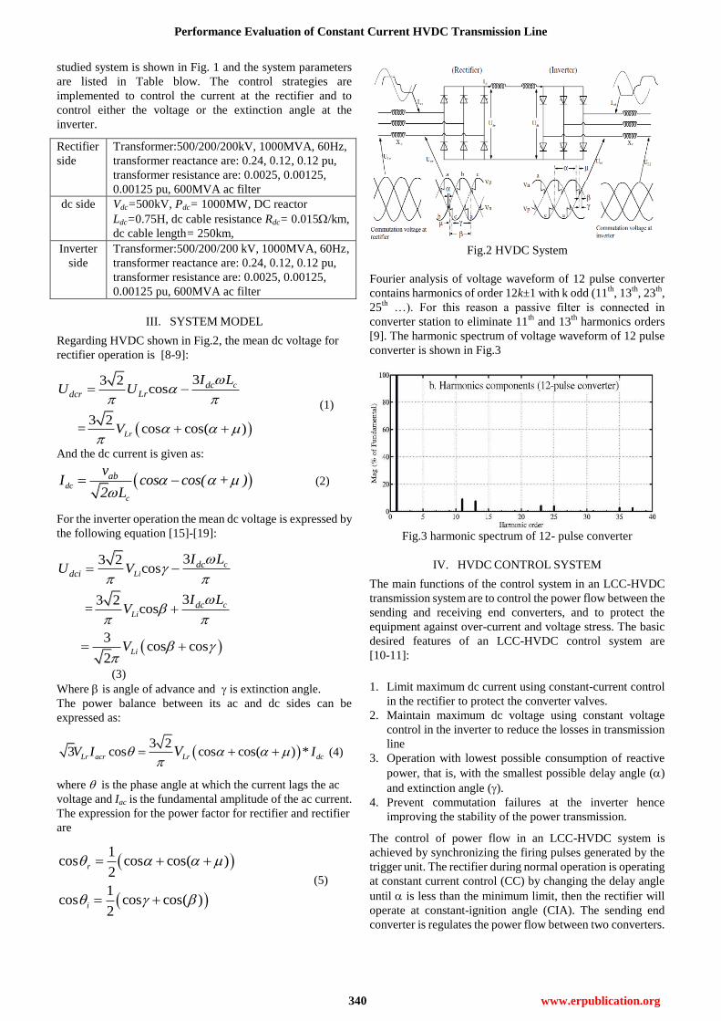
Regarding HVDC shown in Fig.2, the mean dc voltage for
rectifier operation is [8-9]:
33 2cos
3 2 = cos cos( )
c
Lr
dcLrdcr
I LU U
V
(1)
And the dc current is given as:
dc
c
abvI cos cos( + )
2 L
(2)
For the inverter operation the mean dc voltage is expressed by
the following equation [15]-[19]:
33 2cos
33 2 = cos
3 cos cos
2
c
Li
c
Li
Li
dcdci
dc
I LU V
I LV
V
(3)
Where is angle of advance and is extinction angle.
The power balance between its ac and dc sides can be
expressed as:
3 2
3 cos cos cos( ) *Lr acr Lr dcV I IV
(4)
where is the phase angle at which the current lags the ac
voltage and Iac is the fundamental amplitude of the ac current.
The expression for the power factor for rectifier and rectifier
are
1cos cos cos( )
2
1cos cos cos( )
2
r
i
(5)
Fig.2 HVDC System
Fourier analysis of voltage waveform of 12 pulse converter
contains harmonics of order 12k±1 with k odd (11th
, 13th
, 23th
,
25th
…). For this reason a passive filter is connected in
converter station to eliminate 11th
and 13th
harmonics orders
[9]. The harmonic spectrum of voltage waveform of 12 pulse
converter is shown in Fig.3
Fig.3 harmonic spectrum of 12- pulse converter
IV. HVDC CONTROL SYSTEM
The main functions of the control system in an LCC-HVDC
transmission system are to control the power flow between the
sending and receiving end converters, and to protect the
equipment against over-current and voltage stress. The basic
desired features of an LCC-HVDC control system are
[10-11]:
1. Limit maximum dc current using constant-current control
in the rectifier to protect the converter valves.
2. Maintain maximum dc voltage using constant voltage
control in the inverter to reduce the losses in transmission
line
3. Operation with lowest possible consumption of reactive
power, that is, with the smallest possible delay angle ()
and extinction angle ().
4. Prevent commutation failures at the inverter hence
improving the stability of the power transmission.
The control of power flow in an LCC-HVDC system is
achieved by synchronizing the firing pulses generated by the
trigger unit. The rectifier during normal operation is operating
at constant current control (CC) by changing the delay angle
until is less than the minimum limit, then the rectifier will
operate at constant-ignition angle (CIA). The sending end
converter is regulates the power flow between two converters.

International Journal of Engineering and Technical Research (IJETR)
ISSN: 2321-0869, Volume-2, Issue-9, September 2014
341 www.erpublication.org
Fig.4 shows the block diagram of the rectifier constant current
control system. The actual dc current flowing in the dc link is
compared with the reference value Iord. The resultant error
signal Ie is then passed through a PI controller, the output of
the PI controller is the alpha order ord which controls the
frequency output of the VCO. A limit is used to prevent the dc
current from exceeding the specific value to provide
over-current protection to converter valves.
+ -ref
I
dI
eI
YY
Δ
Ring
counterVCOPI
ordα
max
min
max
min
DC voltage
protection
Fig. 4: Rectifier control system layout.
The control system at receiving end is selective. A control
angle selector is placed to choose the desired control l from
the dc voltage controller, extinction angle control, or current
regulator. The selector chose the control with minimum firing
angle. The control system is similar to the rectifier control
system including the comparing loop, PI controller, VCO, and
counter ring. The schematic block diagram of the inverter
control system is shown in Fig. 5.
+ -ord
Id
I
eI
YY
?
Ring
counterVCO
PIord
α
max
min
max
min
+-
ord ePI
+-
ord ePI
Vdc
Vdc VdcS
E
L
E
C
T
O
R
Fig. 5: inverter control system layout
V. SIMULATION RESULTS
HVDC to transmit the power between two regional networks
with constant current control the following scenarios are
investigated:
1- The first scenario considers change in transmitted
power.
2- The second scenario considers symmetrical fault at
inverter side.
A. System behavior during change in transmitted power
The dc link power can be increased or decreased using power
run-up and run-down controls in response to local or remote
disturbances. The step power change is achieved by adjusting
the current reference value. The dc system behaviour during a
sudden power change is shown in Fig. 6. The difference
between rectifier side dc voltage and inverter dc voltage is
due to dc cable ohmic drop. The current reference value is
stepped down at t=1s from 1.0pu to 0.80pu gradually with a
slope during 0.2s, and then at t=1.8s, it steps up to 1.2pu
during 0.2s as shown in Fig.6a.
The dc voltage at the inverter is kept at constant value by
inverter controller resulting in constant dc voltage at the
rectifier side as shown in Fig. 6d. The rectifier delay angle
(r) is increased during power step-down and decreased
during power step-up as shown in Fig 6c. Since the dc voltage
is kept constant and *dc dcdcP V I , then the dc current is
adjusted by varying the rectifier delay angle in order to
change the transmitted dc power. The ac voltage at the
inverter side is varied proportionally to the change in the
transmitted power and this can be explained using the power
balance equation:
3 2
3 cos cos cos( ) .l l ac dcl lP V I V I
The Total Harmonic Distortion level (THD) on the ac sides is
measured at B1 and B2. The results are compared with the
harmonic level limit of 1.5% stated in the IEEE Std 519-1992.
The THD in the ac voltage at bus B1 is 0.593%, Fig. 6e shows
the voltage waveforms at B1 and B2.
The ability of an LCC-HVDC transmission system to control
the active power flow can be utilized to provide frequency
regulation in the ac network. In this case the power control is
activated when significant change in system frequency occurs.
Therefore the transmitted power is varied to match the new
power demand; the fast change of power achieved by dc
control can improve the ac system transient stability and
damping of electromechanical oscillations from nearby
generators. One practical example of fast power command
changes is the Pacific Intertie system where power command
changes could be initiated at either the inverter or rectifier end
and completed within 50 ms [12].
a- Rctifier and inverter currents

Performance Evaluation of Constant Current HVDC Transmission Line
342 www.erpublication.org
b- DC link power at inverter side
c- Rectifier and inverter delay angles
d- DC voltage at rectifier and inverter converter
e- Voltage at converter ac side
Fig. 6 Waveforms demonstrating HVDC performance during
change in transmitted power
B. Scenario II: System behaviour during symmetrical
fault at inverter side
An ac fault at the rectifier side will lead to temporary lose of
the dc power in-feed to the receiving ac system. Depending on
the ac system strength, an overvoltage may occur in the
converters due to the reactive power compensation devices
connected at the point of common coupling. If the fault occurs
at the inverter side, commutation failure may be associated
with the loss of the dc transmitted power.
At time t=2s a solid three-phase fault-to-ground is applied
close to B2 at the ac side with a fault duration of 5 cycles
(100ms for 50Hz). The results obtained from this scenario are
presented in Fig. 7. When the ac fault occurs at the inverter
side the inverter depressed terminal voltage will either reduce
further or terminate the transmitted dc power,
since .dc dcdcP V I , then both the dc voltages and dc currents
will be affected by the fault. The Vdc and Idc are altered during
the fault period and recover after fault clearance (Fig. 7a and
b).
The protection system forces the delay angle at the rectifier to
increase and convert the operation mode to inversion (see Fig.
7c) when detecting a negative dc voltage caused by voltage
reversal at the inverter side. Therefore the storage energy will
discharge and the fault will be extinguished. The dc system
current contribution to the three-phase short-circuits current is
limited due to the dc system current rating, and no additional
current is injected to the fault location compared to an ac
interconnection. The short-circuit current level will depend
mainly on the short circuit ratio of the ac system. Fig. 6h
shows the ac current measured at bus B2. In a practical
LCC-HVDC system the time for the dc system to recover to
90% of its pre-fault power following ac fault clearing is
typically in the range of 25 ms to 500 ms [12].
It was observed that in LCC-HVDC transmission system any
disturbance in the receiving-end side will affect the
sending-end side which results in non-decoupled operation of
the two ac networks. This is explained by Fig. 7g, the voltage
at B1 is affected by the ac fault at B2, this feature limits the use
of LCC-HVDC systems for wind farm integration because the
wind farm may be affected by the fault and open its breakers,
and this may lead to black-out unless enough reserve
generation is available.
a. Rctifier and inverter currents

International Journal of Engineering and Technical Research (IJETR)
ISSN: 2321-0869, Volume-2, Issue-9, September 2014
343 www.erpublication.org
b- DC voltage at Rctifier and inverter sides
c- Rectifier and inverter delay angles
d- AC current at rectifier side (B1)
e- AC Current at rectifier side
Fig. 7 Waveforms demonstrating HVDC performance during
symmetrical fault at inverter side
VI. CONCLUSION
This paper investigated the potential use of HVDC system for
transmission of power between regional networks at steady
state and transient conditions. It has been illustrated that this
approach is so effective for large scale power transmission
over long distance without reducing transmission losses. Also
the HVDC system could be used to connect networks with
different frequencies. The control system drive converter
station is very important for stable operation. The PI
parameters are chosen using small signal analysis. The
robustness of the control is investigated during several
conditions.
REFERENCES
[1] O. A. Giddani, et al., "Grid integration of alarge offshore wind farm
using VSC-HVDC in parallel with an AC submarine cable," in
Universities Power Engineering Conference (UPEC), 2009
Proceedings of the 44th International, 2009, pp. 1-5."
[2] N. Flourentzou, et al., "VSC-Based HVDC Power Transmission
Systems: An Overview," IEEE Trans on Power Electronics,, vol. 24,
pp. 592-602, 2009.
[3] [3] M. P. Bahrman and B. K. Johnson, "The ABCs of HVDC
transmission technologies," Power and Energy Magazine, IEEE, vol.
5, pp. 32-44, 2007.
[4] [4] D. M. Larruskain, "Transmission and Distribution Networks: AC
versus DC," IEEE Power Engineering Society General Meeting,
24-28 June 2007, pp. 1-5.
[5] [5] T. J. Hammons, et al., "Role of HVDC transmission in future
energy development," Power Engineering Review, IEEE, vol. 20, pp.
10-25, 2000.
[6] [6] P. Bresesti, et al., "HVDC Connection of Offshore Wind Farms to
the Transmission System," Energy Conversion, IEEE Transactions on,
vol. 22, pp. 37-43, 2007.
[7] [7] C. Karawita and U. D. Annakkage," Multi-Infeed HVDC
Interaction Studies Using Small-Signal Stability Assessment", IEEE
Transactions on Power Delivery, VOL. 24, NO. 2, APRIL 2009
[8] [8] O. Wasynczuk, "Modeling and Dynamic Performance of a
Line-Commutated Photovoltaic Inverter System," Power Engineering
Review, IEEE, vol. 9, pp. 35-36, 1989.
[9] [9] P. Kundur, Power System Stability and Control: Electric Power
Research Institute, Power System Engineering Series, 1994.
[10] [10] Z. Chengyong, et al., "A Novel HVDC Transmission System with
Parallel Large Capacitor Connected in the DC Side of the Rectifier and
Its Technical Feasibility," in Transmission and Distribution
Conference and Exhibition: Asia and Pacific, 2005 IEEE/PES, 2005,
pp. 1-5.
[11] [11] Y. Iwatta, et al., "Simulation Study Of A Hybrid Hvdc System
Composed Of A Self-commutated Converter And A Line-commutated
Converter," in Sixth International Conference on AC and DC Power
Transmission, , 1996, pp. 381-386.
[12] [12] Review of HVDC Link Technology Issues, Electricity Network
Investment (ENI), March 2009.
O. A. Giddani received the B.Eng degree (in honors) in power system
and machines from Sudan University of Science and Technology (SUST),
Sudan, in 2001, and the M.Sc degree in electrical power system from SUST.
He is currently a PhD student at the University of Strathclyde, Glasgow, UK,
his research interest include wind power integration and HVDC system.
Abdelaziz Yousif Mohamed Abbas received the B. Tech. (First class
Hons) and M.Sc. degrees from the Sudan University of Science and
Technology, Khartoum, Sudan, in 1996 and 2002, respectively, and the
Ph.D. degree from Strathclyde University, Glasgow, U.K., in 2009, all in
electrical and electronic engineering. From 1996 to 2005, he was a Teaching
Assistant then a Lecturer with Sudan University of Science and Technology,
where he is currently an Assistant Professor. His research interests include
power electronics, drives and energy conversion, power quality and
renewable integration, power systems operation and power systems stability
and control. In addition, Dr. Abbas is a member of the Institution of
Engineering and Technology