performance evaluation for japan isdb-t …wada/papers/itc-cscc2010-sunagawa.pdf · performance...
TRANSCRIPT
PERFORMANCE EVALUATION FOR JAPAN ISDB-T 1SEG SDR PROCESSING
Yuichiro Sunagawa, Katsutoshi Ikenoya, and Tomohisa Wada
Graduate School of Engineering and ScienceUniversity of the Ryukyus, 1 Senbaru Nishihara Okinawa, 903-0213 Japan
ABSTRACT
In order to develop the multi wireless communication servicesby hardware, the cost and time have been increased and cir-cuit size becomes large. Therefore Software defined radio(SDR) is a quite attractive field of research since it can re-duce time consuming prototype development time from re-search themes. SDR can replace hardware problem by soft-ware problem since it define wireless communication systemincluding the radio processing parameter by software. Thispaper presents the architecture of the back-end of “1seg” re-ceiver with the C-language program is configurable. “1seg”receiver developed by SDR turned out to be feasible technol-ogy according to the evaluation of CPU execution time.
Index Terms— Software defined radio, SDR, OFDM,ISDB-T, 1seg, Oneseg, One-seg
1. INTRODUCTION
In recent years, various radio communication systems suchas a cellular phone, wireless LAN, TV boroadcasting are in-vestigated and developed separately by making use of ad-vance of semiconductor technologies. Since each radio sys-tem is implemented with separate hardware components, sys-tem size becomes large and development cost and time havebeen increased in case to support multi wireless communica-tion services. Therefore the Software Defined Radio (SDR)system attracts attention. Since most public software playeris Personal Computer (PC) and size of PC is expected to bemuch small size, it is expected that PC will be used as a SDRterminal with minimum addition of hardware components.Currently, high bandwidth communication system adopt Or-thogonal Frequency Division Multiplex (OFDM) modulation.Then, this paper shows SDR implementation results of JapanDigital TV 1seg receiver system by PC with software pro-gramming.
The contents of this paper is organized as follows. Section2 is about architecture of 1seg receiver developed by SDR.Section 3 is measurement result. The conclusion is given inSection 4.
2. ARCHITECTURE
2.1. ISDB-T 1seg SDR
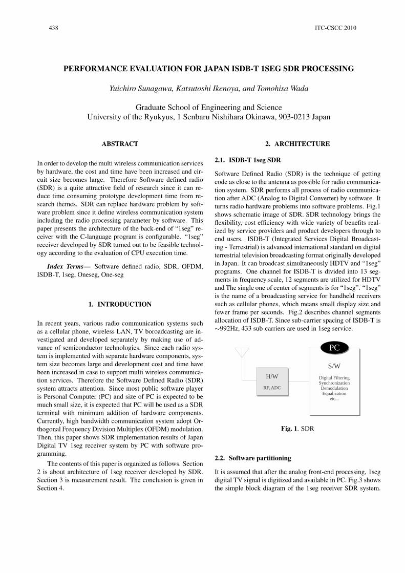
Software Defined Radio (SDR) is the technique of gettingcode as close to the antenna as possible for radio communica-tion system. SDR performs all process of radio communica-tion after ADC (Analog to Digital Converter) by software. Itturns radio hardware problems into software problems. Fig.1shows schematic image of SDR. SDR technology brings theflexibility, cost efficiency with wide variety of benefits real-ized by service providers and product developers through toend users. ISDB-T (Integrated Services Digital Broadcast-ing - Terrestrial) is advanced international standard on digitalterrestrial television broadcasting format originally developedin Japan. It can broadcast simultaneously HDTV and “1seg”programs. One channel for ISDB-T is divided into 13 seg-ments in frequency scale, 12 segments are utilized for HDTVand The single one of center of segments is for “1seg”. “1seg”is the name of a broadcasting service for handheld receiverssuch as cellular phones, which means small display size andfewer frame per seconds. Fig.2 describes channel segmentsallocation of ISDB-T. Since sub-carrier spacing of ISDB-T is∼992Hz, 433 sub-carriers are used in 1seg service.
Fig. 1. SDR
2.2. Software partitioning
It is assumed that after the analog front-end processing, 1segdigital TV signal is digitized and available in PC. Fig.3 showsthe simple block diagram of the 1seg receiver SDR system.
438 ITC-CSCC 2010

Fig. 2. ISDB-T
The input signal is down-converted by FLO/RSMP (Fre-quency local Oscillator/Re-SaMPle) to generate basebandsignal such as complex (a+bj). In this prototype, input signalssampling frequency FS=4.0Msps is assumed by taking realavailable 1seg tuner products into account. Because of ISDB-T “1seg” specification, sampling frequency at FFT (FastFourier Transform) FS=1.0158Msps is necessary. In the firstfunction block FLO/RSMP, baseband signal generation andsampling frequency conversion (re-sample) from 4.0MHzto 1.0158MHz is performed. The second function blockDEROT does de-rotates the re-sample outputs to compensateradio frequency error. FLO, RSMP and DEROT are calleddigital front-end processing. In our approach, SSYNC, FFTand EQ is called digital demodulation. The detail functionsof the components are described following sections (from 2.3to 2.5).
Fig. 3. Simplified block diagram of 1seg SDR processing
2.3. SSYNC
The main task of SSYNC (Symbol SYNChronization) is todetect correct FFT window position. Since 1seg uses ccyclicprefix OFDM signal, the prefix portion namely Guard Inter-val (GI) can be uses to detect the window position. AssumeNPD is OFDM signal length (1024 points), the correlation
can be computed as equation (1) proposed by [1]. Fig.4 de-scribes the image of correlation by equation (1). Simultane-ously, SSYNC detects radio frequency error to feedback theerror to DEROT. By making a feedback loop between DEROTand SSYNC, radio frequency error compensation and track-ing mechanism are implemented. SSYNC receive the inputdata into buffer,then outputs the data which is adjusted to FFTwindow size after success of symbol synchronization.
Λs(kε) =
NP−1∑i=0
{|r(kε)|2 + |r(kε +NPD)|2
}−2
∣∣∣∣∣NP∑i=0
r(kε + i+NPD) · r∗(kε + i)
∣∣∣∣∣ (1)
Fig. 4. Correlation image
2.4. FFT
FFT (Fast Fourier Transform) converts time-domain signalinto frequency domain. This is the demodulation process onOFDM, because orthogonal sub-carriers are used to carrysymbol data. Equation (2) represents the FFT calculation.Equation (2) can change into equation (4) when Wn is de-fined by eqation (3).
X(n) =N−1∑n=0
x(n) · e−j( 2πN )nk(k = 0, 1, . . . , N − 1) (2)
WN = e−j( 2πN ) (3)
X(k) =N−1∑n=0
x(n) ·WnkN (k = 0, 1, . . . , N − 1) (4)
One OFDM time-domain symbol length is 1008µs. Then1024 point FFT with FS=1.0158MHz is required. From FFToutput of 1024 complex points, necessary 1seg”sub-carriersof 433 points are transfered to succeeding EQ block. 1024FFT is expressed in equation 5
X(k) =1023∑n=0
x(n) ·Wnk1024 (5)
The computation of FFT block is based fixed point pro-cessing and Radix-4 multi-stage computation algorithm is
ITC-CSCC 2010 439
used. 1024 FFT in Radix-4 multi-stage computation is ex-pressed in equation (8) when k and n are defined by equation(6)(7)
k = k0 + 4k1 + 16k2 + 64k3 + 256k4 (6)n = n0 + 4n1 + 16n2 + 64n3 + 256n4 (7)
(k0, k1, k2, k3, k4 = 0, 1, 2, 3)
(n0, n1, n2, n3, n4 = 0, 1, 2, 3)
X(k) =3∑
n0=0
3∑n1=0
3∑n2=0
3∑n3=0
3∑n4=0
x(n)Wnk1024 (8)
2.5. EQ
In EQ (EQualizer), there are two main functions. The one ischannels estimation and the other is to remove signal distor-tion by the channel estimation result. Since the FFT outputsof 433 points includes 36 scattered pilot (SP) points, ChannelTransfer Function (CTF) can be computed by the interpola-tion calculation. By divide the FFT output data by the CTF,signal distortion can be compensated. This process is calledas Equalization. In this implementation, 2-dimensional in-terpolation is used such as time domain linear interpolationand frequency domain interpolation. Originally every 12 sub-carriers arranged SP are time-interpolated to generate every 3sub carriers position. After the freauency domain interpora-tion, all position value (CTF) are available. CTF acquirementappearance is shown as Fig.5.
Fig. 5. Equalization
3. MEASUREMENT RESULT
Processing performance of the proposed system is measuredby CPU execution time. Table.1 describes specifications ofthe use PC platform. OFDM parameter of 1seg can be re-ferred to [2].
Table 1. Simulation specificationsMachine Specification
OS Ubuntu 9.10CPU Intel Core 2 Duo 3.06 GHzMemory 4.00 GBLanguage CCompiler gcc version 4.4.1
OFDM parameterFFT window size 1024Symbol size 1008 µsSub-carrier number 433Channel 1-wave, No noize
3.1. Symbol Constellations
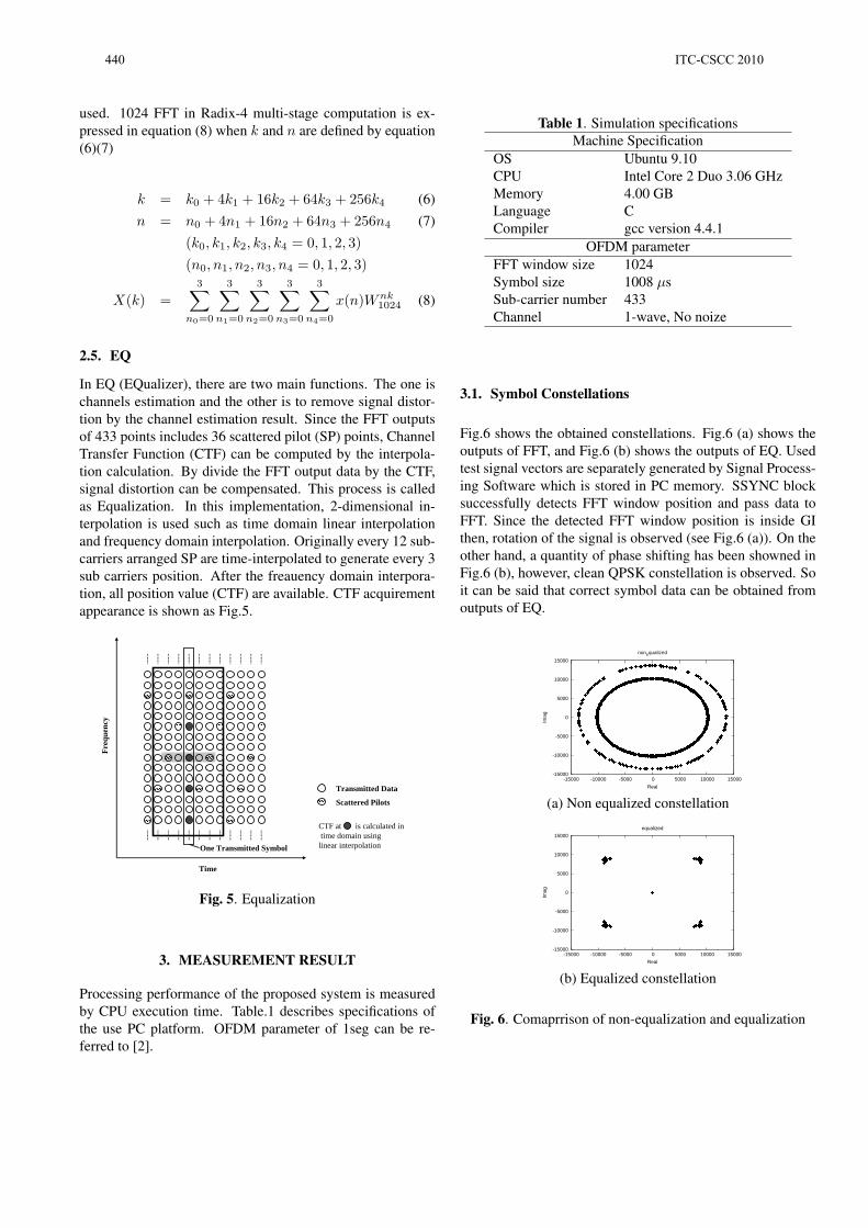
Fig.6 shows the obtained constellations. Fig.6 (a) shows theoutputs of FFT, and Fig.6 (b) shows the outputs of EQ. Usedtest signal vectors are separately generated by Signal Process-ing Software which is stored in PC memory. SSYNC blocksuccessfully detects FFT window position and pass data toFFT. Since the detected FFT window position is inside GIthen, rotation of the signal is observed (see Fig.6 (a)). On theother hand, a quantity of phase shifting has been showned inFig.6 (b), however, clean QPSK constellation is observed. Soit can be said that correct symbol data can be obtained fromoutputs of EQ.
-15000
-10000
-5000
0
5000
10000
15000
-15000 -10000 -5000 0 5000 10000 15000
Imag
Real
nonequalized
(a) Non equalized constellation
-15000
-10000
-5000
0
5000
10000
15000
-15000 -10000 -5000 0 5000 10000 15000
Imag
Real
equalized
(b) Equalized constellation
Fig. 6. Comaprrison of non-equalization and equalization
440 ITC-CSCC 2010

3.2. CPU Execution Time
Fig.7 shows the bar graph of execution time through threefunctions (SSYNC, FFT, EQ) with 100 symbols in the testdata. GCC compiler is utilized in this evaluation. GCC com-piler has optimization options “-Ox”, and there are some op-timization levels (x is the level). The following is the featureof each optimization options which is refered to [3].
• -O option
With -O, the compiler tries to reduce code size and exe-cution time, without performing any optimizations thattake a great deal of compilation time.
• -O2 option
Optimize even more. GCC performs nearly all sup-ported optimizations that do not involve a space-speedtradeoff. As compared to -O, this option increases bothcompilation time and the performance of the generatedcode.
• -O3 option
Optimize yet more. -O3 turns on all optimizationsspecified by -O2 and also turns on the -finline-functions,-funswitch-loops, -fpredictive-commoning, -fgcse-after-reload and -ftree-vectorize options.
One OFDM symbol length of 1seg is 1008µs. In orderto realize real time demodulation process using PC, at least100 symbol processing has to finish within 1008µs × 100second. Without the optimization option, it do not satisfy thecondition. However, it can satisfy this condition when thecompiler optimize its C program.
Fig. 7. Execution time by each gcc options
4. CONCLUSION
This paper proposed Japan ISDB-T 1seg receiver architecturein C programing. Simulation results showed that it’s able toimplement SSYNC, FFT, EQ components in SDR. The test-bench marks 0.05 sec to handle 100 OFDM symbols. So itcan be said that 1seg receiver which is developed by SDR canbe realize.
5. REFERENCES
[1] Michael Speth, Ferdinand Classen, and Heinrich Meyr,“Frame synchronization of ofdm systems in frequency se-lective fading channels,” in Vehicular Technology Confer-ence (VTC’97, 1997, pp. 1807–1811.
[2] ARIB, TRANSMISSION FOR DIGITAL TERRESTRIALTELEVISION BROADCASDING, Std-b31 vesion 1.8 edi-tion, 12 2009.
[3] Richard M. Stallman and the GCC Developer Commu-nity, Using the GNU Compiler Collection, GNU Press adivision of the Free Software Foundation, for gcc version4.4.4 edition, 2003.
ITC-CSCC 2010 441