performance estimates for space shuttle vehicles … · performance estimates for space shuttle...
TRANSCRIPT

a,. . 2
N A S A TECHNICAL NOTE
PERFORMANCE ESTIMATES FOR SPACE SHUTTLE VEHICLES USING A HYDROGEN OR A METHANE-FUELED TURBORAMJET-POWERED FIRST STAGE
by Geruld KniP, Jr., and Joseph D. Eisenberg
N A T I O N A L A E R O N A U T I C S A N D S P A C E A D M I N I S T R A T I O N W A S H I N G T O N , D. C. . J A N U A R Y 1972
https://ntrs.nasa.gov/search.jsp?R=19720007229 2018-06-02T07:11:36+00:00Z

TECH LIBRARY K A F B t NU
~ 0133187 - - " . -. . . . . - 1. Report No. 2. Government Accession No. 3. Recipient's Catalog No.
NASA TN DT6634 ". 4. Title and Subtitle ESTIMATES FOR SPACE
. .. - 5. Revort Date
SHUTTLE VEHICLES USING A HYDROGEN OR A METHANE- FUELED TURBORAMJET-POWERED FIRST STAGE
January 1972 6. Performing Organization Code
~ - . . . . . . . . . - ~ - ~ . .~
7. Author(s) 8. Performing Organization Report No.
Gerald Knip, Jr., and Joseph D. Eisenberg E- 6367 10. Work Unit No.
132- 15 9. Performing Organization Name and Address
Lewis Research Center National Aeronautics and Space Administration I 11. Contract or Grant No.
L __Cleveland, Ohio 44135 i 13. Type of Report and Period Covered
Technical Note National Aeronautics and Space Administration 14. Sponsoring Agency Code
Washington, D. C. 20546 r- I -. - .. . . ~ . ~.
15. Supplementary Notes .- ~.
______ _ _ _ ~ .~ , . .~ ." ". " .. _. - ~
16. Abstract
Two- and three-stage (second stage expendable) shuttle vehicles, both having a hydrogen-fueled, turboramjet-powered first stage, are compared with a two-stage, VTOHL, all-rocket shuttle in terms of payload fraction, inert weight, development cost, operating cost, and total cost. All of the vehicles place 22 680 kilograms (50 000 lb) of payload into a 500-kilometer (270-n-mi) orbit. The upper stage(s) uses hydrogen-oxygen rockets. The effect on payload fraction and vehicle inert weight of methane and methane-flox as a fuel-propellant combination for the three- stage vehicle is indicated. Compared with a rocket first stage for a two-stage shuttle, an airbreathing first stage results in a higher payload fraction and a lower operating cost, but a higher total cost. The effect on cost of program size and first-stage flyback is indicated. The addition of an expendable rocket second stage (three-stage vehicle) improves the payload frac- tion but is unattractive economically.
17. Key Words (Suggested by Author(s)I "" ~-
Hypersonic propulsion Unclassified - unlimited Airbreathing propulsion Space shuttle vehicle Cryogenic fuels
19. Security Classif. (of this report) 20. Security Classif. (of this page) 21. No. of Pages 22. Price'
Unclassified Unclassified 33 $3.00 . ." -
' For sale by the National Technical Information Seivice, Springfield, Virginia 22151


CONTENTS Page
SUMMARY . . . . . . . . . . . . . . . . . . . . . . . . . . . . . . . . . . . . . . 1
INTRODUCTION . . . . . . . . . . . . . . . . . . . . . . . . . . . . . . . . . . . ANALYSIS . . . . . . . . . . . . . . . . . . . . . . . . . . . . . . . . . . . . . .
Vehicle Description . . . . . . . . . . . . . . . . . . . . . . . . . . . . . . Two-stage vehicle . . . . . . . . . . . . . . . . . . . . . . . . . . . . . Three-stage vehicle . . . . . . . . . . . . . . . . . . . . . . . . . . . . Flight path . . . . . . . . . . . . . . . . . . . . . . . . . . . . . . . . . Structures . . . . . . . . . . . . . . . . . . . . . . . . . . . . . . . . . Propulsion . . . . . . . . . . . . . . . . . . . . . . . . . . . . . . . . . Aerodynamics . . . . . . . . . . . . . . . . . . . . . . . . . . . . . . .
cos t . . . . . . . . . . . . . . . . . . . . . . . . . . . . . . . . . . . . . . . Vehicles costed . . . . . . . . . . . . . . . . . . . . . . . . . . . . . . Method of computation . . . . . . . . . . . . . . . . . . . . . . . . . . .
2
4 4 4 5 6 7 9 12 12 12 12
RESULTS AND DISCUSSION . . . . . . . . . . . . . . . . . . . . . . . . . . . . 13 Performance of Two-Stage Fully Reusable Space Shuttles . . . . . . . . . . 14
Vehicle weight breakdown . . . . . . . . . . . . . . . . . . . . . . . . . 14 Structural weight sensitivity . . . . . . . . . . . . . . . . . . . . . . . 14 Effect of decreasing pullup Mach number . . . . . . . . . . . . . . . . . 15 Effect of orbital inclination . . . . . . . . . . . . . . . . . . . . . . . . 15 Effect of first stage flyback . . . . . . . . . . . . . . . . . . . . . . . . 15 Effect of rocket specific impulse . . . . . . . . . . . . . . . . . . . . . 15
Performance of Three-Stage Space Shuttles . . . . . . . . . . . . . . . . . . 16 Payload fraction . . . . . . . . . . . . . . . . . . . . . . . . . . . . . . 17 Weight breakdown . . . . . . . . . . . . . . . . . . . . . . . . . . . . . 17 Effect of fuel and propellant . . . . . . . . . . . . . . . . . . . . . . . . 18
Estimates of Development. Operational. and Total Cost . . . . . . . . . . . 21 First-stage powerplant . . . . . . . . . . . . . . . . . . . . . . . . . . 21 Effect of program size . . . . . . . . . . . . . . . . . . . . . . . . . . 25 Cost of flyback capability . . . . . . . . . . . . . . . . . . . . . . . . . 26 Addition of expendable stage . . . . . . . . . . . . . . . . . . . . . . . 28
CONCLUDING mMARKS . . . . . . . . . . . . . . . . . . . . . . . . . . . . . . 28
m F E m N C E S . . . . . . . . . . . . . . . . . . . . . . . . . . . . . . . . . . . . 29
iii
.

PERFORMANCE ESTIMATES FOR SPACE SHUllLE VEHICLES USING A HYDROGEN
OR A METHANE-FUELED TURBORAMJET-POWERED FIRST STAGE
by Gerald Knip, Jr., and Joseph D. Eisenberg
Lewis Research Center
SUMMARY
Two- and three-stage (second stage expendable) shuttle vehicles, both having a hydrogen-fueled, turboramjet-powered first stage, are compared with a two-stage, VTOHL (vertical-takeoff, horizontal- landing), all-rocket shuttle in terms of payload fraction, inert weight, development cost, operating cost, and total cost. All of the vehicles place 22 680 kilograms (50 000 lb) of payload into a 500-kilometer (270-n-mi) orbit. The upper stage(s) uses hydrogen-oxygen rockets. The effect on payload fraction and vehicle inert weight of methane and methane - fluorine oxygen (flox) as a fuel- propellant combination for the three-stage vehicle is indicated.
When compared with a rocket first stage for a two-stage shuttle, an airbreathing first stage results in a 55-percent increase in payload fraction (1.72 against 1.11) . However, the total inert weight is 92 percent heavier. As a result, the development cost is higher. Although the manufacturing and the refurbishment costs are greater for the airbreathing vehicle because of its higher inert weight, the launch operating cost is less. This results in a lower operating cost for the airbreathing vehicle.
In terms of total cost, the airbreathing vehicle is more expensive and, therefore, less attractive than the all-rocket vehicle. The airbreathing vehicle does not appear to be competitive on a cost basis except for a program requiring 1000 launches or more. The effect of first-stage flyback on performance and cost is minor.
The addition of an expendable second stage to the airbreathing vehicle increases the payload fraction by 41 percent and decreases the vehicle inert weight by 34 percent. However, except for a program requiring fewer than 60 launches, it is not economically competitive with the two- stage airbreathing shuttle.
For the three-stage vehicle, a fuel-propellant combination of hydrogen and hydrogen-oxygen is superior to methane and methane-flox.

, I INTRODUCTlON
In the past, NASA and the aerospace industry have generated a great deal of interest in a reusable booster or space shuttle vehicle. Such a vehicle will have a lower operat- ing cost than current expendable boosters.
References 1 to 6 considered a number of reusable booster concepts. These varied from the relatively simple scheme of parachute recovery of present day expendable rocket stages to the more advanced two- stage, fully reusable booster. The studies con- sidered many propulsion systems for the reusable first stage. These included rocket, pure airbreathing (turbojet, turboramjet, and dual mode ramjets), combination (turbojet plus rocket), and composite (ejectoramjet, scramlace) engines.
Current studies are of a two-stage, fully reusable, oxygen-hydrogen, rocket- powered, vertical-takeoff, horizontal-landing (VTOHL) shuttle (refs. 7 to 9). For these studies only rocket propulsion is being considered because of the desire for an early operational date in the 1970's. Reference 3 indicates that an airbreathing engine for primary propulsion of the first stage would delay the operational date by an additional f ive years.
Prior studies using airbreather propulsion for the first stage considered either JP or hydrogen for fuel. Hydrogen is superior to JP in terms of heating value and cooling capacity (table I). However, hydrogen, being a cryogenic, causes tankage and safety problems. Its other disadvantages are its low density and high cost. Reference 1 indi- cates that, based on payload fraction, hydrogen is better than JP. A preliminary NASA study indicated methane may be a promising fuel for this application.
TABLE I . - COMPARISON O F HYDROGEN, METHANE,
Hydrogen Methane
Heating value
2 1 000 18 750 '
T AND JP FUEL CHARACTERISTICS
". . .
Heat sink - j Density I c o s t
J/kg
10.9x10⁶ 2 .6 0. 38X1O6 t o
0. 85X106 I - I
Btu/lb
15 to 25 33 to 55 4.43 70.97 4700
d / l b 1 4 /kg ' k g / m 3 ~ 1 lb/ft3
1100 1 .2 to 2 2 . 6 t o 4 . 4 26 416.52
165 to 365 1.8 3.97 50 801
~
2

Compared with hydrogen, methane is less expensive and denser, but has a lower heating value (table I). Therefore, the actual advantage due to using m e w e rather than hydrogen will depend on the tradeoff between structural weight and fuel weight.
The purpose of the present study is two-fold. The first is to compare on the basis of a consistent set of ground rules the merits of two hydrogen-fueled turboramjet vehicles (table II) with those of a proposed rocket-powered VTOHL space shuttle (ref. 8). One of the turboramjet vehicles consists of two, fully reusable stages. The other con- sists of two reusable stages plus an expendable second stage. All stages except the first employ rocket propulsion. The VTOHL vehicle is composed of two fully reusable oxygen-hydrogen rocket stages. These vehicles are compared on the basis of launch weight, payload fraction, inert (dry) weight, development cost, operational cost, and total cost.
TABLE II. - VEHICLES AND PROPELLANTS INVESTIGATED
Space shuttle concept
1 2 3 4
Reusable booster (turboramjet
powered)
Hydrogen Hydrogen Methane Methane
Expendable second stage
_""""""" Hydrogen- oxygen Hydrogen- oxygen
Methane-flox
Reusable orbiter
Hydrogen- oxygen Hydrogen- oxygen Hydrogen- oxygen
Methane- flox
The second objective is to determine the effect of using methane rather than hydro- gen as fuel for a three-stage vehicle. Hydrogen and methane are investigated for the reusable turboramjet first stage (table II). For the two rocket upper stages, the propel- lants considered are hydrogen-oxygen and methane - fluorine oxygen (flox). The second stage is expendable while the third is reusable.
kilograms (50 000 lb) of useful payload and provides 283.2 cubic meters (10 000 ft3) of storage volume. Other payload levels were not studied. The airbreathing first stage accelerates the vehicles to pullup Mach numbers of between 5.5 and 8. The pullup Mach number was optimized for the all-hydrogen vehicles and the three-stage vehicle using methane in the first stage and hydrogen-oxygen in the upper stages. After staging, rockets propel the upper stage(s).
at 28.5' and 55'. The initial orbit has a perigee of 83 kilometers (45 n mi) and an apogee of 185 kilometers (100 n mi). Propellant for a post-orbital velocity increment of 457 meters per second (1500 ft/sec) is provided to (1) transfer from the initial orbit to
For both the two- and three-stage vehicles, the final stage or orbiter carries 22 680
Mission velocity requirements are based on an eastward launch into orbits inclined
3

a circular orbit at 500 kilometers (270 n mi) and (2) initiate reentry. Estimates df development, operational, and total costs for a 10-year program are
presented for the two hydrogen-fueled airbreathing vehicles. These costs are compared with those for the all-rocket shuttle. The effect on cost of program size, first-stage flyback, and the addition of an expendable rocket second stage is indicated.
AN ALY S 1 S
Vehicle Description
The present study investigates four space shuttle concepts (table II) for the mission of placing 22 680 kilograms (50 000 lb) of payload into a 500-kilometer (270-n-mi) orbit. One vehicle is composed of two fully reusable stages (fig. 1). The remaining three vehicles are composed of three stages - a reusable first stage, an expendable second stage, and a reusable third stage. All of the first stages are accelerated by turboram- jets. The upper stages are rocket powered. Hydrogen and hydrogen-oxygen were con- sidered for the first and second stages of the two-stage vehicle. In addition to hydrogen and hydrogen-oxygen, methane and methane-flox were considered for the first and the two upper stages, respectively, of the three-stage vehicle.
Two-stage vehicle. - Both stages of the two-stage vehicle are wingbody configura- tions (fig. 1). Based on previous studies, a reentry wing loading of 2863 newtons per square meter (60 lb/ft ) was used to size the wing of the second or orbiter stage. Ref- erence 8 used a value of 3350 newtons per square meter (70 lb/ft ). A low wing loading is desirable for reducing the landing speed and the reentry heating load. However, it also results in increased inert weight. Thus, a compromise is involved. The area of the vertical tails is equal to 16 percent of the wing area (17 percent, ref. 8). The wing and the vertical tails have a thickness ratio of 5 percent and an aspect ratio of 1.5. The fuselage has a conical forebody and a cylindrical afterbody. The forebody has a fineness ratio (length to diameter, L/D) of 5.76 and a diameter equal to 80 percent that of the first stage. Stage length varied to accommodate the required propellant. The orbiter is mounted in parallel with the first stage and partially submerged to reduce vehicle drag.
fuselage is 15. It has a conical forebody (L/D = 5.72), a cylindrical center section (L/D = 7.78), and a conical afterbody (L/D = 1.5). The wing has a delta planform with a 69' leading edge sweep angle, a 5-percent thickness ratio, and a 0.076-meter (0.25-ft) leading edge diameter. Wing area varied with takeoff gross weight so as to maintain a loading of 4309 newtons per square meter (90 lb/ft ) of wing planform area.
2 2
first-stage geometry was based on reference 10. The overall fineness ratio of the
2
4

""""
123.5 m (405 f t ) -4 - -
1
(a) Turboramjet f i rst stage.
- """_A"_ ' '7
(b) Rocket second stage.
Figure 1. - Example of airbreathing shuttle vehicle considered in t h i s study.
For the standard case both the airbreathing stage of the two-stage vehicle and the booster stage of the all-rocket vehicle return to the launch site after staging. The case of no flyback was also considered for the airbreathing stage. Without flyback the air- breathing stage carried a reserve which equaled 10 percent of the total fuel load and landed at a site down range. With flyback the weight of the reserve fuel equaled that of the no flyback case having the same pullup Mach number. Therefore, for a given pullup Mach number, the actual reserve weight is the same for both cases.
three-stage vehicle is the same as for the two- stage vehicle. However, the second stage is expendable. The two upper stages are arranged in tandem and mounted in parallel with the airbreathing first stage. In addition to hydrogen and hydrogen- oxygen,
Three-stage vehicle. - The geometry of the reusable first and third stages of the
5

methane and methane-flox were considered for the first and the two upper stages, re- spectively. With hydrogen fuel, the first stage is volume limited. With methane, vol- ume in excess of that required for fuel storage had to be incorporated into the first stage to accommodate the length of the upper stage.
Flight path. - The flight path, figure 2, followed by the airbreathing first stage was subject to various constraints. Two of these were dynamic pressure (9) and engine inlet face pressure. Dynamic pressure affects the stage structural weight; engine face pres- sure affects the weight of the airbreathing engines. For the present study, the dynamic
60 a
40
20
E 30
10
I -","r- /
0 L 0 1 2 3 4 5 6 7 a Mach number
Figure 2. - Flight path for airbreathing first stage.
pressure and the engine face pressure were limited to 95 760 newtons per square meter (2000 lb/ft ) and 1.379 million newtons per square meter (200 psi), respectively. These values a re taken from reference 11.
2
From takeoff to Mach 1, the vehicle follows a typical flight path for an airbreathing booster. Between Mach 1 and 2, the dynamic pressure is increased to the 95 760 new- tons per square meter (2000 lb/ft ) limit by flying at essentially constant altitude. The vehicle continues to accelerate along a flight path characterized by a dynamic pressure of 95 760 newtons per square meter (2000 lb/ft ) until it attains Mach 4.5. Above Mach 4.5, the flight path is dictated by the 1.379 million newtons per square meter (200 psi) engine face pressure constraint.
2
2
Between Mach 5.5 and 8 or prior to staging the vehicle initiates a 1.5- g pullup maneuver. The vehicle continues to climb at this g loading until it attains a 0.44 radian (25') angle of attack. This angle of attack is maintained until the maximum flight
6

path angle is attained. At this point the upper stage is launched and the first stage con- tinues to the apogee of its trajectory.
a 83-kilometer (45-n-mi) perigee and a 185-kilometer (100-n-mi) apogee.
clined at 0.45 (28.5') and 0.96 radian (55'). Propellant for a post-orbital velocity in- crement of 457 meters per second (1500 ft/sec) was provided for transferring to a 500-kilometer (270-n-mi) circular orbit and to initiate reentry.
The upper stage uses a linear-tangent thrust program to an elliptical orbit having
The mission velocity requirement was based on eastward launches into orbits in-
First-stage flyback to the takeoff site was considered for the two-stage vehicle. Initially three return flight paths were studied. Of these, the path shown in figure 2 resulted in the highest payload fraction. This path is similar to the descent path used in other airbreathing booster studies.
After the first stage reaches the apogee of its trajectory, the turboramjet engines - a r e shut down and the stage descends to a speed of Mach 5 and an altitude of 28 346 meters (93 000 ft). The engines a r e then started and the stage makes a powered turn (load factor = 1.5) until it is alined with the takeoff site. It continues to cruise at Mach 5 until it is able to glide the remaining distance to the takeoff site. Early in the study a cruise Mach number of 5 was found to result in the highest payload fraction; thus, this value was fixed for the res t of the study.
Structures. - Structural weights for the all-rocket shuttle are still uncertain (refs. 8 and 12 show considerable deviation). This is even more true for an airbreathing vehicle. However, the weight estimating technique used here for the airbreather seems to yield structural weights that a r e consistent with those of reference 8. Therefore, the relative performance of the two systems should be correct.
Structural weights for the first stage yere based on a hot structure and calculated according to the empirical equations of reference 13. These equations were determined from data for current subsonic airplanes and supersonic fighters and bombers. The resultant data were corrected in the reference to account for the more severe thermal environment at hypersonic speeds. The corrections were based on point design tests of numerous panels each subjected to a given temperature. For the present study, the structural skin temperature was based on the equilibrium temperature corresponding to the maximum pullup Mach number and the associated angle of attack. This temperature was determined for a f la t plate having a turbulent boundary layer, an emissivity of 0.8, and a reference length. For the wing and the fuselage, the reference length equaled one- half of the centerline chord length and one-third of the fuselage length, respectively.
To indicate the credibility of the resultant weights, typical structural weight factors are presented at this point in the report. Figure 3 compares the structural weight factors for the fuselage and the wing of the airbreathing and the rocket-powered first stage (ref. 8).
7

L Rocket booster (ref. 8)
Fuselage Wing
Figure 3. - Structural weight factors for airbreathing booster. Thermal protection system not included.
The fuselage of the airbreathing stage has a structural unit weight factor of 44 kilo- grams per square meter (9 lb/ft ) of surface area. The weight of the nonintegral fuel tanks and the thermal protection system is excluded. In comparison, the rocket- powered first stage has a value of 28.3 kilograms per square meter (5.8 lb/ft ). One would expect the airbreathing stage to have a higher structural factor than the rocket stage for two reasons: One reason is the greater dynamic pressure (therefore higher loadings and temperatures) to which the airbreathing stage is exposed, and the second is the penalty for submerging the upper stage.
2
2
The structural unit weight factor for the wing of the airbreathing stage is 39 kilo- grams per square meter (8 lb/ft ) of planform area against 34 kilograms per square meter (7 lb/ft ) for the rocket-powered first stage. Because of different geometry and design conditions it is difficult to compare the two values.
2 2
Fuel for the airbreathing booster is stored in nonintegral aluminum tanks located within the fuselage. Tank weight (considering three tanks and the vehicle geometry) was based on a structural weight factor of 7.3 kilograms per square meter (1.5 lb/ft ) of surface area. The tanks were insulated to protect them from the hot structure. This type of structural arrangement may not result in the lowest structural weight. The in- sulation limits the temperature of the empty tanks to 93' C (200' F) s o as to maintain their structural integrity. The weight of insulation, 10.7 kilograms per square meter (2.2 lb/ft ), was based on reference 14 which used ADL- 17 (a vacuum powder). An in- house study indicated a value of 7.3 kilograms per square meter (1.5 lb/ft ) using dyna- quartz. However, the in- house study did not account for any heat leaks through the sup- port structure.
2
2 2
8

For the expendable stage, 10 percent of the propellant weight is assumed to equal the weight of the structure. The weight of the propulsion system equals 3 percent of the initial stage weight (ref. 13).
The inert weight (structure plus propulsion) of the orbiter, designed for a payload of 22 680 kilograms (50 000 lb), is based on an empirical equation derived from previous studies :
WmERT = 34 020 + 0.173 (WACC + Wpo)kg
W m R T = 75 000 + 0.173 (WACC + Wpo)lb
where WAcc is the acceleration propellant and W the propellant for 457 meter per second (1500 ft/sec) post-orbital maneuvers.
As for the first stages, estimates of inert weights for the orbiters are still not
PO
firmly established at this time. For example, in a later study (ref. 12), the inert weight of the orbiter for the VTOHL rocket vehicle (ref. 8) has increased by 14 percent because of refinements and changes in ground rules. Since the missions for the orbiters of the airbreathing and the all-rocket vehicle are similar, one would expect the inert weight of the orbiter for the airbreathing vehicle to also increase. Thus, the compari- sons made in this study between the present airbreathing shuttle and the VTOHL rocket shuttle of the earlier study (ref. 8) should still be valid.
Propulsion. - Inline turboramjets in the first stage and rockets in the upper stage(s) accelerate the payload to orbital velocity. The turboramjets accelerate the vehicle from takeoff to Mach numbers of between 5.5 and 8. The airbreathing engines are located beneath the wing with the inlet operating in the wing pressure field and the noz- zle in the free stream. A two-dimensional variable geometry inlet designed for full capture above Mach 4 .5 supplies air to the engines. An additive drag based on the re- quired wedge angle and the engine mass flow schedule was taken into account. The inlet engine face pressure is limited to 1.379 million newtons per square meter (200 psi) (ref. 11) for the given pressure recovery schedule (MILE-5008B, ref. 15) by increas- ing the altitude while accelerating. The characteristics of the engines operating as afterburning turbojets (from takeoff to Mach 3.1) are as follows:
Design compressor pressure ratio . . . . . . . . . . . . . . . . . . . . . . . . 8 Primary combustor efficiency . . . . . . . . . . . . . . . . . . . . . . . . 0.98 Turbine inlet temperature, K (OR):
Hydrogen . . . . . . . . . . . . . . . . . . . . . . . . . . . . . 2033 (3660) Methane. . . . . . . . . . . . . . . . . . . . . . . . . . . . . . 1478 (2660)
Afterburner combustor efficiency . . . . . . . . . . . . . . . . . . . . . . 0.93
9
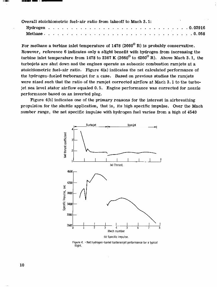
Overall stoichiometric fuel-air ratio from takeoff to Mach 3.1: Hydrogen . . . . . . . . . . . . . . . . . . . . . . . . . . . . . . .0.02916 Methane. . . . . . . . . . . . . . . . . . . . . . . . . . . . . . . . .0.058
For methane a turbine inlet temperature of 1478 (2660’ R) is probably conservative. However, reference 6 indicates only a slight benefit with hydrogen from increasing the turbine inlet temperature from 1478 to 2367 K (2660’ to 4260’ R). Above Mach 3.1, the turbojets are shut down and the engines operate as subsonic combustion ramjets at a stoichiometric fuel-air ratio. Figure 4(a) indicates the net calculated performance of the hydrogen-fueled turboramjet for a case. Based on previous studies the ramjets were sized such that the ratio of the ramjet corrected airflow at Mach 3.1 to the turbo- jet sea level stator airflow equaled 0.5. Engine performance was corrected for nozzle performance based on an inverted plug.
Figure 4(b) indicates one of the primary reasons for the interest in airbreathing propulsion for the shuttle application, that is, its high specific impulse. Over the Mach number range, the net specific impulse with hydrogen fuel varies from a high of 4540
Turbojet - Ramjet I -I
(a) Thrust.
U W v)
- E- 3800 -
E n 3
.- E3400 U -fi U al VI n
3000 26oOO - , , ,7, 1 2 3 4 5 6 7 8
Mach number
(b) Specific impulse.
Figure 4. -Net hydrogen-fueled turboramjet performance for a typical flight.
10

seconds impulse
at Mach 2 to a low of 2700 seconds at Mach 7.6. In comparison, the specific for a oxygen-hydrogen rocket is about 400 seconds.
The lower specific impulse for the ramjet at Mach 3.1 is due to the basic ramjet cycle. Based on the difference in specific impulse between the turbojet and the ramjet at Mach 3. I, it may be better to delay the changeover to the ramjet mode to a more opti- mum point. However, this was not investigated in the present study.
Fourteen airbreathing engines are used in the first stage of the fully reusable, two- stage vehicle compared to twelve engines for the three-stage vehicle. In general, the thrust requirement of the engines is dictated by the transonic portion of the flight path. This is the usual case for hypersonic vehicles.
For each pullup Mach number, the engine sea level static airflow was varied to maximize the payload fraction. The optimum engine airflow was similar for both the two- and the three-stage vehicles. The minimum allowable thrust margin ((F - D)/D) in the transonic speed range was 40 percent. A higher thrust margin resulted in a re- duced payload fraction.
Weights for the basic turboramjet (without inlet) engines were calculated according to an empirical equation derived from other studies:
W~~~ = 62 300 ( wa @B 7' 21b 2532
where
W a d % ~- - turbojet sea-level static corrected airflow
6
The weight of the two-dimensional inlet was based on references 13 and 16. The rocket stages had an initial thrust to gross weight ratio of 1.0. Each of the two
rocket engines of the second stage of the two-stage vehicle had a specific impulse of 459 seconds (97 percent theoretical) and a thrust of about 2 224 000 newtons (500 000 lb). This combination of thrust and impulse could be achieved by a rocket having a chamber pressure of about 20.68 million newtons per square meter (3000 psi) and a nozzle expan- sion ratio of approximately 120.
For methane-flox a specific impulse of 400 seconds was used (ref. 17). If the same nozzle exit diameter is maintained (because of dimensional limitations) for the methane- flox as for hydrogen-oxygen, this level of impulse can be achieved by a rocket having a
11
I
c

chamber pressure of about 5.52 million newtons per square meter (800 psi) and an ex- pansion ratio of about 40.
Aerodynamics. - The l i f t and drag for each configuration were determined by total- ing the values of the contributing components. At transonic and supersonic speeds the wave drag components of the zero-lift drag coefficient were determined from a correla- tion of data (ref. 18) and linearized theory. At hypersonic speeds, Newtonian theory (ref. 19) was used. Blunt leading edge drag for the wing and inlet and vertical tails was included (refs. 18 and 19).
The skin friction component of the zero-lift drag coefficient was taken into account by (1) using the Prandtl-Schlichting equations to calculate an incompressible skin fric- tion coefficient for a f l a t plate with a turbulent boundary layer and (2) correcting the incompressible value for compressibility effects by the reference enthalpy method. The Reynolds number was based on the length of the fuselage and the mean aerodynamic chord of the wing and the vertical tails.
References 19 to 21 were used in determining the lift-curve slope for the first stage. The drag due to l i f t was calculated from the induced drag factor which equaled the recip- rocal of the l i f t curve slope.
cost
Once the engine, structure, fuel, and propellant weights a re known, the costs for a given program can be calculated. The purpose of this part of the study was not to deter- mine actual costs with unerring certainty but to compare on the same basis the costs of several shuttle vehicles.
Vehicles costed. - Development, operational, and total costs are determined for three vehicles. One is the VTOHL, fully reusable, two-stage, oxygen-hydrogen rocket vehicle of reference 8. The other two a re the hydrogen-fueled, two- and three-stage vehicles considered in the present study.
Method of computation. - The procedure used to determine the costs of the three vehicles was, in general, based on the relations and curves in reference 22. Several additions to these relations were included. Costs were adjusted to approximate 1970 rather than 1966 dollars by assuming four years of 6 percent inflation (ref. 23). This adjustment should not be taken to mean that a space shuttle will be developed and built in the 1970's. Refurbishment costs were based on reference 24 and equaled approxi- mately 1 percent of the stage manufacturing cost per flight. The manufacturing cost was calculated on the basis of a 90-percent learning curve.
12

RESULTS AND DISCUSSION
The aerospace industry is currently studying under NASA contract a number of rocket-powered space shuttle vehicles. One of these vehicles (ref. 8) stages at a veloc- ity of 3292 meters per second (10 800 ft/sec) and achieves a maximum payload fraction of 1.11 percent (fig. 5). The second stage is accelerated by two high pressure (20.68 million N/m (3000 psi)), high expansion ratio (120), oxygen-hydrogen rockets having a specific impulse of 459 seconds (97 percent of the theoretical impulse).
2
Rocket propulsion is also being used for the first stage. One reason for this is the desired operational date (1970's). If these date were extended, airbreathing propulsion for the first stage could be a contender. These engines would be used for the accelera- tion phase and for flyback. Both stages of the rocket powered shuttle employ turbojet engines for flyback (subsonic).
0 Payload
2. 5x10⁶ Propellant, second stage Propellant, first stage Inert weight, second stage
-First-stage TR J R propulsion: First-stage Hydrogen Hydrogen-oxygen
propulsion:
Figure 5. -Weight breakdown for two ful ly reusable two-stage shutt le vehicles with flyback. One f i r s t stage i s powered by hydrogen-fueled turboramjets and one by hydrogenaxygen rockets; both second stages are powered by hydrogen- oxygen rockets; orbits, 500 kilometers (270 n mi); orb i t in- cl ination, 55O; payload, 22 680 kilograms (50 OOO Ib).
13

Performance of Two-Stage Fully Reusable Space Shuttles
This section discusses the performance of the two-stage shuttle having an airbreath- ing first stage and compares its performance with that of the VTOHL, all-rocket shuttle of reference 8.
Vehicle weight breakdown. - For a payload of 22 680 kilograms (50 000 lb), the minimum takeoff gross weight (TOGW) for the turboramjet-powered vehicle is 1.3 mil- lion kilograms (2.9 million lb) against 2.04 million kilograms (4.5 million lb) for the all-rocket shuttle (fig. 5). This represents a 55-percent increase in payload fraction, 1.72 against 1.11. The minimum TOGW for the airbreathing shuttle is attained at a pullup Mach number of 7.6. The resultant staging velocity is 2229 meters per second (7312 ft/sec). Higher staging velocities (3048 to 3658 m/sec; 10 000 to 12 000 ft/sec (ref. 24)) would require the development of a supersonic combustion ramjet engine.
The main reason for the decrease in TOGW is the lower fuel consumption of the first-stage airbreathing engines. These engines required 0.26 million kilograms (0.58 million lb) of hydrogen compared to 1.40 million kilograms (3.08 million lb) of oxygen- hydrogen for the first-stage rockets.
On the negative side, the total inert weight of the airbreathing vehicle is almost twice that of the all-rocket vehicle 0.66 against 0.34 million kilogram (1.46 against 0.76 million lb). For both vehicles, most of the inert weight is due to the first stage. The airbreathing stage accounts for 85 percent of the total inert weight. This compares to 73 percent for the first stage of the all-rocket vehicle.
The second- stage gross weights are 0.49 and 0.39 million kilograms (1.09 and 0.87 million lb) for the airbreathing and the all-rocket vehicle, respectively. The inert weight of the rocket second stage for the airbreathing vehicle represents 20 percent of the second-stage gross weight. This compares with 24.8 percent for the second stage of the all-rocket vehicle (20.6 percent with the present inert weight equation).
When vehicle inert weight is used as an indication of manufacture cost, figure 5 indicates that the all-rocket vehicle may be the least expensive of the two vehicles. However, at this time structural weights are still not firmly established.
Structural weight sensitivity. - Because structural weights are subject to change, the sensitivity of TOGW to stage inert weight is indicated in figure 6. Note that the TOGW of the airbreathing vehicle is less sensitive to increases in stage (first or second) inert weight than the all-rocket shuttle. A 10-percent increase in the first-stage inert weight results in a 5.2- and a 7-percent increase in the TOGW of the airbreathing and the all-rocket shuttle, respectively. A similar increase in the inert weight of the orbiter results in a 7.3-percent increase in the TOGW of the airbreathing shuttle com- pared to 12.5 for the all-rocket shuttle. Thus, a 10-percent increase in the inert weight of each stage results in a 12.5-percent increase in the TOGW of the airbreathing vehicle against 19.5 percent for the all-rocket vehicle.
14

L1or 0 Ref. 8
v) In Operating weight empty ratio, OWE/OWErd
Operating weight empty ratio, OWE/OWErd
(b) Second stage.
Figure 6. - Sensitivity of vehicle takeoff gross weight (TOGW) to stage operating weight empty (OWE) for a fully reusable two-stage shuttle vehicle. Hydrogen-fueled turboramjet first stage; hydrogen-oxygen rocket upper stage; orbit, 500 kilometers (270 n mi); payload, 22 680 kilograms (50 M)o Ib).
Effect of decreasing pullup Mach number. - Development problems associated with an airbreathing stage capable of attaining Mach 7.6 may be reduced by decreasing the pullup Mach number. Decreasing it from 7.6 to 6 results in only a 7-percent reduction in the payload fraction (fig. 7).
Effect of orbital inclination. - Because the ground rules for a space shuttle vehicle a re not firm at the present time, the effect of orbital inclination on vehicle payload fraction is indicated in figure 7 for an eastward launch from a latitude of 0.5 radian (28.5O). Decreasing the inclination from 0.96 to 0.5 radian (55' to 28.5') results in an 11-percent increase in the maximum payload fraction. Throughout the remainder of this discussion an inclination of 0.5 radian (28.5') will be used.
powered first stage) returns to the launch site. If instead it lands at a nearby base (not the launch site), eliminating the need for flyback fuel (no-flyback case), the maximum
Effect of first-stage flzback. - After staging, the airbreathing stage (and the rocket- "_ " "
. payload fraction is increased by 16 percent (fig. 7). Effect of rocket specific impulse. - Up to this point, the second stage has been
accelerated by two oxygen-hydrogen rockets having a chamber pressure of 20.7 million
15
i

Orbit Flyback Specific incl ination, impulse,
deg SeC
55 With 459 0 2 8 5 Wi th 459
c A 2 8 5 Without 459 E U 0 2 8 5 Without 450 L W CL
1 I 6 7
Pullup Mach number
F igure 7. -Effect of various parameters on payload fraction of two- stage f u l l y reusable shuttle vehicle. Turboramjet f irst stage; rocket second stage; orbit, 500 kilometers (270 n mi); payload, 22 680 kilograms (50 000 Ib).
newtons per square meter (3000 psi) and a nozzle expansion ratio of 120. This combin- ation results in a specific impulse of 459 seconds. A chamber pressure of 20.7 million newtons per square meter (3000 psi) represents an advanced engine requiring new tech- nology. If the chamber pressure and the expansion ratio are decreased to 14.8 million newtons per square meter (2150 psi) and 80, respectively, the corresponding specific impulse is 450 seconds for the same exit diameter. This 9-second reduction in specific impulse results in a 6.7-percent decrease in the maximum payload fraction for the no- flyback case.
This same reduction in second-stage specific impulse for the all-rocket vehicle results in a 4-percent decrease in the payload fraction (ref. 7). The all-rocket vehicle is less sensitive to second-stage specific impulse because of its higher staging velocity. Although it is less sensitive, a high chamber pressure is being considered because the engine will also be used for the first stage which operates at a higher ambient pressure. An engine common to both stages will result in a lower development cost. However, for the airbreathing vehicle, a lower chamber pressure rocket may have a cost advantage.
Performance of Th ree-Stage Space Shuttles
Depending on the total number of launches required, a three-stage vehicle with an expendable second stage may be cost effective. Therefore, the effect on performance of adding an expendable second stage to the previous two-stage, fully reusable airbreath- ing shuttle was determined. The expendable stage accelerates the reusable third stage (orbiter) from the staging point to a velocity of 6584 meters per second (21 600 ft/sec).
16

I
For the case considered, this staging velocity resulted in the highest payload fraction. Payload fraction. - The addition of an expendable oxygen-hydrogen (specific
impulse = 459 sec) rocket second stage increases the payload fraction and reduces the optimum pullup Mach number. Compared with a payload fraction of 2.2 percent for the two-stage shuttle (with no flyback), figure 8, the payload fraction for the three-stage vehicle is 3.1 percent or 41 percent greater. The optimum pullup Mach number de- creased from 7.6 to 6.8. Decreasing the pullup Mach number from the optimum to 6 results in a 5-percent reduction in payload for the three-stage vehicle compared to 12 .1 for the two-stage shuttle.
'r I Number U w e r staQels)
6 7 Pullup Mach number
8
Figure 8. - Comparison of payload fractions for two shuttle vehicles and effect of pullup Mach number pr ior to ini t ial staging (only second stage of three-stage vehicle is not reusable). Turboramjet powered f i rs t stages; no first-stage flyback; orbit, 500 kilometers (270 n mi); orbi t incl inat ion, 28.5O; payload, 22 680 kilograms (50 000 Ib).
Decreasing the specific impulse of the rocket stages of the three-stage vehicle from 459 to 433 seconds results in a 8.3-percent decrease in the payload fraction. In com- parison, a 9-second decrease in the specific impulse of the second stage of the two- stage fully reusable shuttle resulted in a 6.7-percent decrease. A specific impulse of 433 seconds could be achieved by a rocket having a chamber pressure of about 6.2 mil- Lion newtons per square meter (900 psi) and an expansion ratio of 30. This represents current 5-2 technology.
Weight breakdown. - The addition of an expendable stage reduces not only vehicle takeoff gross weight but also vehicle inert weight (fig. 9). The takeoff gross weight decreases from 1.03 million kilogranis (2.28 million lb) for the two-stage airbreathing shuttle to 0.73 million kilograms (1.61 million lb) for the three-stage vehicle. Simi- larly the total inert weight decreases &om 0.516 to 0.34 million kilograms (1.14 to
17

2.4~106
(51 1. 2 .-
n L
: t n
n Payload Propellant, t h i r d stage Propellant, second stage Fuel , f i rst stage Inert weight, third stage Inert weight, second stage Inert weight, f irst stage
v
First-stage fuel: Hydrogen Hydrogen Second-stage propellant: Hydrogen- Hydrogen-
Third-stage propellant: --------- Hydrogen- oxygen oxygen
oxygen
Figure 9. -Weight breakdown comparison for two space shutt le vehicles - one a ful ly reusable two-stage vehicle, and the o ther a three-stage vehicle having a nonreusable second stage. Optimum pul lup Mach number. Turboramjet powered f i rs t stage; hydrogen-oxygen rocket upper stage(s); no first-stage flyback; orbit, 500 kilograms (270 n mi); orbital inclination, 28.5O; payload, 22 680 kilograms (50 OOO Ib).
0.75 million lb). This could represent a cost savings depending on the size of the space program. The cost aspect will be discussed later.
The stage inert weights for stages 1 to 3 represent 37, 9.5, and 42 percent of the respective initial stage gross weights. The increase in the orbiter's inert weight from 20 percent for the two-stage vehicle to 42 percent for the three-stage vehicle is a size effect.
Thus, compared to a fully reusable, two-stage vehicle, the addition of an expend- able second stage decreases the required takeoff gross weight and the vehicle inert weight. It also reduces the sensitivity of the payload fraction to pullup Mach number (that is, staging velocity) and upper stage specific impulse. Any cost advantage result- ing from a lower vehicle inert weight will depend on the size of the space program and, therefore, the number of second stages expended.
Effect of fuel and propellant. - Vehicle cost is related to inert weight. But inert weight is related to fuel and propellant density; therefore, a fuel and propellant denser than hydrogen and hydrogen- oxygen may be advantageous. One such fuel-propellant combination is methane and methane-flox. However, compared with hydrogen and hydrogen-oxygen, they result in a lower specific impulse. Any improvement, therefore, will depend on the tradeoff between inert weight and fuel (propellant) consumption.
When methane is used in place of hydrogen in the first stage of the three-stage
18
-First-stage fuel ,- Propellant for upper stages
I 6 7 8
Pul lup Mach number
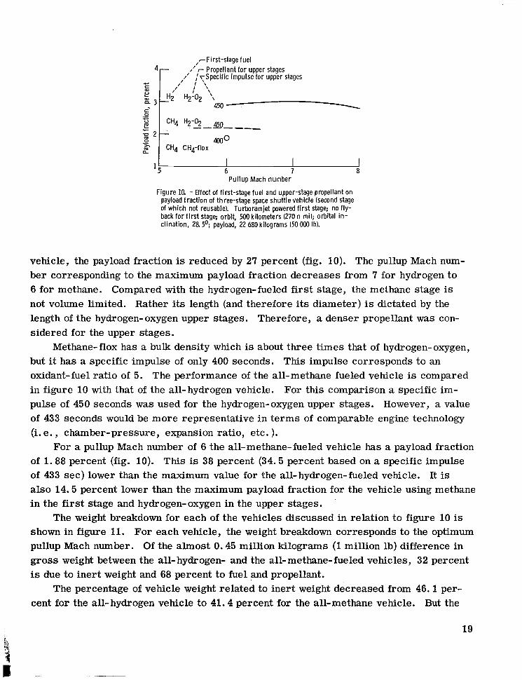
Figure la - Effect of first-stage fuel and upper-stage propellant on payload fract ion of three-stage space shuttle vehicle (second stage of which not reusable). Turboramjet powered f i rs t stage; no fly- back fo r f i r s t stage; orbit, 500 kilometers (270 n mi); orbital in- clination, 28 5'; payload, 22 680 kilograms (50 OM) Ib).
vehicle, the payload fraction is reduced by 27 percent (fig. 10). The pullup Mach num- ber corresponding to the maximum payload fraction decreases from 7 for hydrogen to 6 for methane. Compared with the hydrogen-fueled first stage, the methane stage is not volume Limited. Rather its length (and therefore its diameter) is dictated by the length of the hydrogen-oxygen upper stages. Therefore, a denser propellant was con- sidered for the upper stages.
Methane-flox has a bulk density which is about three times that of hydrogen-oxygen, but it has a specific impulse of only 400 seconds. This impulse corresponds to an oxidant-fuel ratio of 5. The performance of the all-methane fueled vehicle is compared in figure 10 with that of the all-hydrogen vehicle. For this comparison a specific im- pulse of 450 seconds was used for the hydrogen-oxygen upper stages. However, a value of 433 seconds would be more representative in terms of comparable engine technology (i. e., chamber-pressure, expansion ratio, etc. ).
For a pullup Mach number of 6 the all-methane-fueled vehicle has a payload fraction of 1.88 percent (fig. 10). This is 38 percent (34.5 percent based on a specific impulse of 433 sec) lower than the maximum value for the all-hydrogen-fueled vehicle. It is also 14.5 percent lower than the maximum payload fraction for the vehicle using methane in the first stage and hydrogen-oxygen in the upper stages.
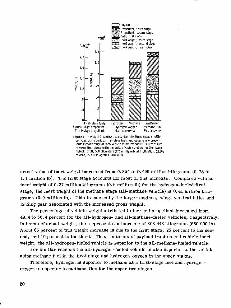
The weight breakdown for each of the vehicles discussed in relation to figure 10 is shown in figure 11. For each vehicle, the weight breakdown corresponds to the optimum pullup Mach number. Of the almost 0.45 million kilograms (1 million lb) difference in gross weight between the all-hydrogen- and the all-methane-fueled vehicles, 32 percent is due to inert weight and 68 percent to fuel and propellant.
The percentage of vehicle weight related to inert weight decreased from 46.1 per- cent for the all-hydrogen vehicle to 41.4 percent for the all-methane vehicle. But the
19
1.4~10' r 2.8x10⁶
2.4 c 2.0 c
0 Payload Propellant, t h i r d stage Propellant, second stage
0 Inert weight, th i rd stage Inert weight, second stage Inert weight, f i rst stage
Fuel, f i r s t stage
-First-stagkfuel: Hydrogen Methane Methane Second-stage propellant: Hydrogen-oxygen Methane-flox
Third-stage propellant: Hydrogendxygen Methane-flox
Figure 11. -Weight breakdown comparison for three space shutt le vehicles using various first-stage fuels and upper-stage propel- lants (second stage of each vehicle is not reusable). Turboramjet powered f i rs t stage; optimum pul lup Mach number: no f i rst stage flyback; orbit, 500 kilometers (270 n mi); orbital incl ination, 2 8 . 5 O ; payload, 22 680 kilograms (50 OOO Ib).
actual value of inert weight increased from 0.354 to 0.499 million kilograms (0.78 to 1 . 1 million lb). The first stage accounts for most of this increase. Compared with an inert weight of 0.27 million kilograms (0.6 million lb) for the hydrogen-fueled first stage, the inert weight of the methane stage (all-methane vehicle) is 0.41 million kilo- grams (0.9 million lb). This is caused by the larger engines, wing, vertical tails, and landing gear associated with the increased gross weight.
The percentage of vehicle weight attributed to fuel and propellant increased from 49.4 to 56.4 percent for the all-hydrogen- and all-methane-fueled vehicles, respectively. In terms of actual weight, this represents an increase of 308 448 kilograms (680 000 lb). About 65 percent of this weight increase is due to the first stage, 25 percent to the sec- ond, and 10 percent to the third. Thus, in terms of payload fraction and vehicle inert weight, the all- hydrogen-fueled vehicle is superior to the all-methane-fueled vehicle.
For similar reasons the all-hydrogen-fueled vehicle is also superior to the vehicle using methane fuel in the first stage and hydrogen-oxygen in the upper stages.
Therefore, hydrogen is superior to methane as a first-stage fuel and hydrogen- oxygen is superior to methane-flox for the upper two stages.
20

Estimates of Development, Operational, and Total Cost
A space shuttle cannot be judged only on its performance. Because it is intended to replace existing expendable boosters, it should preferably offer an economic as well as an operational advantage to warrant its development. Although certain areas such as structural weights cannot be exactly determined, an estimate of development, opera- tional, and total costs has been made. Even if absolute magnitudes should be in error , hopefully the relative costs of the systems studied may offer some guidance.
of two, fully reusable, two-stage vehicles based on a 500 mission program (ref. 8) . The first stages are accelerated by different propulsion systems and use different modes of takeoff. With a VTOHL, oxygen-hydrogen rocket stage (ref. 8), the development, oper- ational, and total cost are 5.9, 7.8, and 13.7 billion dollars (based on the cost estima- tion method of the present report). With an HTOHL, hydrogen-fueled, turboramjet first stage, these same costs are 8.9, 7, and 15.9 billion dollars. Thus, for a 10 year, 500
First-stage powerplant. - Figure 12 compares the development and the total costs
Development 0 Total
i Air brea ther
-
Rocket of reference 8
F igure 12. - Effect of first-stage propulsion on cost for 500 f l ights in 10 years. Orbital plane inclination, 55O; rocket specific impulse, 459 seconds (wi th f ly - back capability).
21

mission program, the VTOHL all-rocket shuttle is the least expensive in terms of total cost. However, the airbreathing shuttle has a slightly lower operating cost. Increasing the staging velocity of the airbreathing shuttle by means of supersonic combustion ram- jets does not alter these results (ref. 24).
Table III presents a detailed cost breakdown for the two, two-stage shuttles con- sidered for the 500 mission program (11.34 million kg - 25 million lb into orbit in 10 yr - 50 flights/yr).
two largest development costs. Together they account for more than half of the total development cost for each vehicle. Stage engineering cost is the cost related to design- ing each of the stages. Test hardware includes airframes, astrionics, and engines associated with both stages of the vehicle that are expended in ground and flight testing prior to the operational phase. For the present study, these components added up to four vehicles. These costs are subject to change because of uncertainties in the area of structural weights. This is especially true for the airbreathing vehicle. The sensi- tivity of stage engineering cost for the airframe of the airbreathing stage to the airframe weight is indicated by means of the following example. A 50-percent reduction in the airframe weight of the airbreathing stage results in a 20-percent reduction in the air- frame stage engineering cost for that vehicle.
From table m(a) it is seen that stage engineering and test hardware costs are the
The cost of procuring airframes, astrionics, and engines for the development phase of the program accounts for 62, 2, and 36 percent of the total test hardware cost. Costs associated with the first two items are a function of its weight, whereas engine cost is a function of thrust. A 50-percent reduction in the airframe weight of the airbreathing stage results in a 35-percent reduction in the airframe test hardware cost for that stage. This same reduction in airframe weight would also result in about a 35-percent decrease in the cost of the airbreathing engines, assuming the same thrust-to-weight ratio. Since the all-rocket vehicle has a lower inert weight than the airbreather, any advancements in stage structural technology will have a greater effect on reducing the development cost of the airbreathing vehicle.
Another possibility for decreasing the test hardware cost is to reduce the number of research and development vehicles. The present costs a r e based on procuring five airbreathing vehicles and five VTOHL rocket vehicles. Only one of each of these vehicles enters the operational phase of the program.
In terms of operational costs (manufacturing costs plus operating costs), table III(b) indicates that vehicle procurement and refurbishment costs are very large for both vehicles. Again the cost to manufacture each vehicle is mainly a function of its weight and the number of vehicles required for the program. To reduce this cost one must strive to reduce airframe weight, to make use of as many research and development vehicles in the operational phase as is possible, and to improve the life expectancy of each vehicle.
22

h3 W
TABLE ID. - COST BREAKDOWN FOR PROGRAM TO PLACE 11.34 MILLION KILOGRAMS
(25 MILLION LB) INTO ORBIT IN 10 YEARS (500 FLIGHTS IN 10 YEARS)
(a) Development costs (b) Costs during operational period (first costs plus operations costs); number of vehicles, 5; vehicle life, 100 flights
, I , Vehicle typea
I
Vehicle typea
RR - AB/R RR - R/R RR - AB/R RR - R/R (b 1 ( C )
I
Gross weight, kg (lb) I
1.3X10⁶ (2. 9X10⁶) I 2. 04X106 (4. 5X10⁶)
Cost, millions of 1970 dollars l-
Stage engineering Engine development Astrionics development Vehicle systems
integration Manufacturing test
facility Ground test facility Ground test operations Flight test operations Test hardware Test fuel Development program
management Vehicle transportation
tes t Total
2104 962 227 884
135
123 50
157 3534
130 574
. 2
8880.2
"
984 69 9 227 49 5
133
112 46
23 4 2328
135 45 1
.2
5844.2
Launch site facility Ground support equipment Vehicle cost (airframe
engines) Refurbishment Launch operations Operational program
management Facility maintenance Product improvement Operations propellant Vehicle transportation Total
I
Gross weight, kg (lb)
4-
1. 3X10⁶ (2. 9X10⁶) 1 2. O4x1O6 (4. 5X10⁶)
Cost, millions of 1970 dollars
112 179
263 8
2389 509 326
408 132 246
.3 6939.3
390 3 06
1815
1777 1738 417
974 9 1
214 .3
7722.3
aTwo-stage fully reusable, RR; both stages rocket powered, R/R; turboramjet first stage, rocket second stage, AB/R. bWeight and cost, present study. 'Weight, ref. 25; cost, present study.

For the present study, five airbreathing and five VTOHL vehicles were assumed to be required for the operational phase of the program (100 percent reliability - no attri- tion). Each vehicle has a life expectancy of 100 flights.
The cost of launch operations for the VTOHL vehicle (ref. 8) is of the same order of magnitude as the vehicle procurement and refurbishment costs j u s t discussed. However, compared to the value for the VTOHL vehicle the cost of launch operations for the air- breathing vehicle is significantly lower. This cost is less for the airbreathing vehicle because (1) it has a lower gross weight, and (2) only two off-pad assembly areas were assumed compared to five for the VTOHL rocket vehicle.
The operations (fuel and propellant) costs are about equal (214 against 246 million dollars, table III(b)) even though the airbreathing vehicle has a higher effective specific impulse. Although the total weight of fuel plus propellant is less for the airbreathing vehicle, the total weight of hydrogen is greater. And since hydrogen and oxygen were assumed to cost 66 and 4.4 cents per kilogram (30 and 2 $/lb), the operations costs are comparable.
Based on these cost calculations, it is obvious that both development and operational costs are controlled by a few items. Up to this point, the costs have been based on the procedure of reference 22. Because of differences in costing techniques, it is interest- ing to compare costs for a specific vehicle and mission. Figure 13 compares costs calculated for this study with those estimated by an airframe company (ref. 25) for the VTOHL rocket vehicle. Only the gross costs were available for this latter study, not the ground rules. Therefore, the costs are compared on this basis. The results are
14r Reference 25 0 Present study
l2 t Total
Opera
._ c 0 Z 6 " VI Develop 0 ment
2 4L
1 "- Highest estimate
Total
Development
1 ---Highest estimate
I " 300 f l ights in 10 years 500 f l ights in 10 years
Figure 13. - Comparison of costs calculated in present study for a two-stage rocket shutt le vehicle with those of reference 25.
24

indicated for two launch rates - 300 and 500 flights in 10 years. For both launch rates, the total costs calculated for the present study are higher.
For 300 and 500 launches, the present computations indicate total costs of 10.9 and 13.6 billion dollars compared with 9.1 and 10.1 billion dollars for reference 25. To indicate the possible variation that might be expected from the data used in generating their cost estimating relations, reference 25 indicated that the total cost might be 16 percent higher (high estimate). Compared with this estimate, the total costs for 300 flights are nearly equal. For 500 flights the total cost computed herein is still 17 per- cent higher. The present development costs are slightly lower, but the operational costs are higher. Compared with a development cost of 5.8 billion dollars, reference 25 estimated 6.9 billion dollars. Thus, the operating costs calculated with the present computations are over twice those of the lower estimate of reference 25, but they do compare more favorably with the higher estimate.
Because they were derived for this specific VTOHL vehicle, the development and operating costs of reference 25 are probably the more exact. Differences in a few items (e. g., refurbishment cost, number of vehicles, number of launch pads, etc. ) can readily account for the discrepancies between the two techniques. The real purpose of this study is, however, not to determine the actual cost with unerring certainty, but rather to compare on the basis of the same cost computation, the development, operational, and total costs of different vehicles. Therefore, for consistency the costs presented from here on are based on the present cost computations.
Effect of program size. - The effect of program size (number of flights in a 10-yr period) on total and operating costs for the all-rocket and the airbreathing vehicle is indicated in figure 14. These costs are presented on a per weight of payload into orbit basis.
For a program requiring 100 launches per year for 10 years (1000 flights), the total costs for the airbreathing and the all-rocket vehicle are equal. For a program requir- ing fewer flights, the all-rocket vehicle is the least expensive. Its total cost decreases from 1594 dollars per kilogram (723 $/lb) of payload for a program requiring 300 flights in 10 years to 948 dollars per kilogram (430 $/lb) for 1000 flights. For the smaller program, the cost associated with the airbreathing vehicle is 410 dollars per kilogram (186 $/lb) higher.
Although the total cost is higher for the airbreathing vehicle, the operating cost may be lower. Based on the present computations, the operating cost for the airbreathing vehicle varies from 699 to 567 dollars per kilogram (317 to 253 $/lb) of payload as the number of flights in 10 years increases from 300 to 800. In comparison, the operating cost for the all-rocket vehicle varies from 734 to 650 dollars per kilogram (333 to 295 $/lb) of payload. Based only on vehicle procurement and refurbishment costs (table III(b)), the rocket vehicle is less expensive. But with the addition of ground costs (launch site facility, ground support equipment, launch operations, and facility main-
25

900
800 Ai rbrea th ing f i r s t stage
\ Rocket f i r s t stage
;5; m
" VI 0 U
11 600 8oo+ -" Operations """""_
200 400
300 400 500 600 700 800 900 1000 Number of f l ights in 10 y r
Figure 14. -Comparison of specific total cost. Orbital plane inclination, 550; rocket specific impulse, 459 seconds (with flyback capability).
tenance), the operating cost for the rocket shuttle is higher. If it is assumed that the ground costs for the rocket vehicle are equal to the ground costs calculated for the air- breathing vehicle, then the rocket vehicle is again less expensive.
Based on the present costing procedure, the airbreathing vehicle is more attractive than the all-rocket vehicle in terms of a lower operating cost. However, based on total program cost, the airbreathing vehicle is more expensive and, therefore, less attract- ive than the all-rocket vehicle. If the overall level of the operating cost is lower than calculated herein (i. e., ref. 25), then the airbreathing vehicle is even less attractive.
Cost of flyback capability. - One possible approach for reducing the costs of either the rocket or the airbreathing shuttle would be to eliminate first-stage flyback after staging. This was considered for the airbreathing vehicle. The effect on both total and development costs is indicated in figure 15. With flyback, the total and the development costs are greater by 1.2 and 0.6 billion dollars, respectively. This is due to the greater weight of the vehicle with flyback. The takeoff gross weight is 1.2 million kilo- grams (2.65 million lb) with flyback compared with 1.03 million kilograms (2.27 million lb) without. For this latter case, the first stage would land at a nearby base (not the takeoff site) after separation. No ferry back cost is included. However, table III(b) indicates that transportation costs are not critical. The increase in cost due to the fly- back capability could possibly be reduced by further optimization of the return flight path.
26

"r
Flyback No flyback
Figure 15. - Effect of first-stage flyback capability on cost of two-stage fully reusable vehicle with turboramjet powered f i r s t stage for 500f l ights in 10years. Orbital plane in- clination, 28'; rocket specific impulse, 459 seconds.
24 - "_ Two-stage all reusable vehicle, a i rbreathing f i rst stage
expendable second stage, airbreathing f i rst stage
22 - - Three-stage vehicle with
20 -
L" 18- m
0 U
0
c 0 v) 16 -
I I
.- n +- 14- VI 0 "
"_ Two-stage all reusable vehicle, a i rbreathing f i rst stage
- Three-stage vehicle with expendable second stage, airbreathing f i rst stage
I I
0
0 0
0 0'
0
Number of f l ights in 10 yr
Figure 16. - Effect on total cost of adding an evendable rocket Stage. No f i r s t stage flyback; orbital inclination, 28.5'; Specific impulse, 459 Sec- onds.
27

Addition of expendable stage. - The addition of an expendable second stage to an otherwise fully reusable two-stage vehicle reduces the total vehicle inert weight. Since cost is related to inert weight, an expendable stage was considered for reducing the total cost of the airbreathing shuttle. Figure 16 indicates a savings of 0.8 billion dollars in development cost. However, because each flight requires another expendable stage, operating costs are very much dependent on the size of the program. Figure 16 indi- cates that in terms of total cost, an expendable second stage is beneficial only for a pro- gram requiring fewer than 60 flights in 10 years.
CONCLUDING REMARKS
This study compares a two and a three-stage vehicle, each having a reusable turbo- ramjet powered first stage, with a fully reusable, VTOHL, two-stage, oxygen-hydrogen rocket shuttle. All the vehicles place 22 680 kilograms (50 000 lb) of payload into a 500-kilometer (270-n-mi) orbit. The airbreathing stage is hydrogen-fueled while oxygen-hydrogen is used in the rocket stages. The vehicles are compared on the basis of launch weight, payload fraction, inert weight, development cost, operational cost, and total cost.
In addition, methane and methane-flox are investigated for the three-stage vehicle, the second stage being expendable.
Comparing the fully reusable, two-stage shuttles, an airbreathing first stage results in a launch weight of 1.3 million kilograms (2.9 million lb) compared with 2.0 million kilograms (4.5 million Ib) for the all-rocket shuttle. This represents a 55-percent im- provement in payload fraction (1.72 against 1.11 percent). However, the airbreathing stage also results in a 92-percent increase in total vehicle inert weight (0.66 against 0.34 million kg (1.46 against 0.76 million lb)) which is related to cost.
Although the present cost study is too Limited and the structural weights too uncer- tain to state that the total costs (for 500 launches) are absolutely correct, nevertheless, several conclusions may be drawn.
Since the technology for an airbreathing first stage is less developed than for a rocket stage, and since the inert weight of the airbreathing vehicle is greater than that for the rocket vehicle, the development cost is higher for the airbreathing vehicle. Stage engineering and test hardware costs (both functions of inert weight) are the two largest development costs. Together they account for more than half of the total devel- opment cost for each vehicle. But each cost is higher for the airbreathing vehicle be- cause of its greater inert weight.
The .airbreathing vehicle results in a lower operational cost (manufacturing plus operating) than the all-rocket vehicle. Although the manufacturing and refurbishment costs are higher for the airbreathing vehicle because of its greater inert weight, the
28
launch operating cost is lower. This cost is lower because of the higher specific impulse of the airbreathing stage and, therefore, the lower takeoff gross weight of the airbreath- ing vehicle. This factor combined with its horizontal takeoff capability greatly simpli- fies ground handling.
Although the fuel plus oxidant weight is less for the airbreathing vehicle, the pro- pellant costs for both vehicles are about equal. This is due to the greater amount of hydrogen used by the airbreathing vehicle and the fact that hydrogen is substantially more expensive than oxygen. Therefore, there is no cost advantage in terms of propel- lant cost due to using an airbreathing first stage.
Although the operational cost for 500 launches is lower for the airbreathing vehicle, it is more expensive in terms of total cost and, therefore, less attractive than the all- rocket vehicle. Based on the current study, the airbreathing vehicle does not appear to be competitive except for a program requiring 1000 launches or more. If the overall level of the operational cost is lower, such as quoted by industry, then the airbreathing vehicle is even less attractive on a cost basis.
The effect of first-stage flyback on the payload fraction and the total cost of the air- breathing vehicle is slight. Without flyback the payload fraction is increased by 16 per- cent. As a result, the total cost for 500 flights is reduced by 8 percent.
The addition of an expendable rocket second stage to the airbreathing vehicle (no flyback) increases the payload fraction by 41 percent. It also decreases the vehicle inert weight by 37 percent. However, based on total cost, it is cost effective only for programs requiring fewer than 60 launches in 10 years.
Based on launch weight and vehicle inert weight, hydrogen is superior to methane as a fuel for the turboramjet first stage of a three-stage shuttle. For the rocket powered upper stages, hydrogen-oxygen is superior to methane-flox as a propellant.
Lewis Research Center, National Aeronautics and Space Administration,
Cleveland, Ohio, October 22, 1971, 132-15.
REFERENCES
1. Peoples, P. L. ; Zeck, H. ; Edmonds, D. S. ; and Omoth, M. J. : Performance and Cost Analysis of Advanced Rocket and Airbreathing Launch Systems. Proceedings of 'the 3rd AIAA and NASA Manned Space Flight Meeting. Publication CP- 10, A M , 1964, pp. 339-352.
29

2. Whiting, T. R. : Design Considerations of Reusable Launch Vehicles. Vol. IV: Maneuverable Class Vehicles, Book 1. Rep. DAC-57915, Douglas Aircraft Co. (NASA CR-80292), Oct. 1966.
3. Fellenz, Dietrich W. ; and Akridge, Charles M. : Design Considerations for Orbital Transport Systems. NASA TM X-53636, 1967.
4. Francis, R. H. : Air-Breathing Reusable Launchers. Space Technology Conference Proceedings. Conf. R o c . P-16, SAE, 1967, pp. 169- 174.
5. Escher, William J. D. ; Flornes, Bruce J.; and Frank, Harry: Results of a Study of Composite Propulsion Systems for Advanced Launch Vehicle Applications. Presented at the Second Propulsion Joint Specialist Conference. U. S. Air Force Academy, Colorado Springs, Colorado, June 13-17, 1966.
6. Knip, Gerald, Jr. ; and Allen, John L. : Analysis of Booster Systems With a Recov- erable Hypersonic Airplane First Stage. Paper 64-543, AIAA, May 1964.
7. Anon. : Space Shuttle. Vol. It - Final Vehicle Configurations. Rep. GDC-DCB69- 046, vol. 2, General Dynamics/Convair (NASA CR-102550), Oct. 31, 1969.
8. Anon. : Study of Integral Launch and Reentry Vehicle System. Volume 11: Tech- nology Development Requirements. Rep. SD- 69- 573-2, North American Rockwell Corp. (NASA CR-102106), Dec. 1969.
9. Anon. : A Two-Stage Fixed Wing Space Transportation System. Vol. I: Condensed Summary. Rep. MDC-E0056, vol. 1, McDonnell-Douglas Astronautics Co. (NASA CR-102086-), D ~ c . 15, 1969.
10. Petersen, Richard H. ; Gregory, Thomas, J. ; and Smith, Cynthia L. : Some Com- parisons of Turboramjet-Powered Hypersonic Aircraft for Cruise and Boost Mis- sions. J. Aircraft, vol. 3, no. 5, Sept.-Oct. 1966, pp. 398-405.
11. Gregory, Thomas J. ; Petersen, Richard H. ; and Wyss, John A. : Performance Tradeoffs and Research Problems for Hypersonic Transports. J. Aircraft, vol. 2, no. 4, July-Aug. 1965, pp. 266-271.
12. Anon. : Space Shuttle Phase B- 180 Day Review. Rep. SD71-4, North American Rockwell Corp., Jan. 1971.
13. Thompson, W. R. : Weight and Size Analyses of Advanced Cruise and Launch Vehicles. Vol. 1: Final Technical Report and Data Handbook. Rep. GDC-DCB 66 008, vol. 1, General Dynamics/Convair (NASA CR-89451) Feb. 1966.
14. Dickson, J. A. : Thermal Protection with a Temperature Capability to 2500' F for Cool Structures. Proceedings of the AFOSR Conference on Aerodynamically Heated Structures. Peter E. Glaser, ed. Rentice-Hall, Inc., 1962, pp. 111-139.
30

15. Anon. : Engines, Aircraft, Turbojet and Turbofan, Model Specification for (Outline and Instructions for Preparation). Military Specification MILE-5008C, Dec. 30, 1965.
16. Jensen, Roger: Weight Estimation of Hypersonic Inlets. Paper 655, SOC. Aeron. Weight Eng., May 1968.
17. Oglebay, Jon C. ; Sagerman, Gary D. ; and Valentine, Harold H. : Analytical Eval- uation of Space Storable Propellants for Unmanned Jupiter and Saturn Orbiter Missions. NASA TM X- 1793, 1969.
18. Stoney, William E., Jr. : Collection of Zero- Lift Drag Data on Bodies of Revolu- tion from Free- Flight Investigations. NASA TR R- 100, 1961.
19. Truitt, Robert W. : Hypersonic Aerodynamics. Ronald Press Co., 1959.
20. Walker, Harold J. ; and Wolowicz, Chester H. : Theoretical Stability Derivatives for the X- 15 Research Airplane at Supersonic and Hypersonic Speeds Including a Comparison with Wind-Tunnel Results. NASA TM X-287, 1960.
21. Harmon, Sidney M. ; and Jeffreys, Isabelle: Theoretical Lift and Damping in Roll of Thin Wings with Arbitrary Sweep and Taper at Supersonic Speeds. NACA TN 2114, 1950.
22. Johnson, D. R. : Design Considerations .of Reusable Launch Vehicles. Vol. V: Launch Vehicle Cost Program: Book 1 - Cost Program Formulation. Rep. DAC-57916, Douglas Aircraft Co. (NASA CR-80298), Oct. 1966.
23. Anon. : NASA Budget Estimate, Bureau of the Budget Submission FY1971.
24. Gregory, Thomas J. ; Williams, Louis J. ; and Wilcox, Darrell E. : The Airbreath- ing Launch Vehicle for Earth Orbit Shuttle-Performance and Operation. Paper 70-270, AIAA, Feb. 1970.
25. Anon. : Study of Integral Launch and Reentry Vehicle System. Vol. V: Operations and Resources. Rep. SD- 69- 573- 5, North American Rockwell Corp. (NASA CR- 102107), D ~ c . 1969.
NASA-Langley, 1972 - 31 E-6367 31

! ,
N A T I O N A L A E R O N A U T I C S A N D S P A C E A D M I S T R A T I O N WASHINGTON. D.C. 20546
POSTAGE AND FEES PAID NATIONAL AERONAUTICS AND
SPACE ADMINISTRATION OFFIC IAL BUSINESS FIRST CLASS MAIL. PENALTY FOR PRIVATE USE $300 USMAIL
0 2 9 ‘301 C 1 U 3 1 711217 S00903DS DEPT OF THE A I R FORCE AF WEllPONS L A B I A F S C I T E C H LIBRARY/WLOL/
KTP.TLAND AFR NM 57117 ATTN: E LOU R O W M 4 N ~ CHIEF
mSTMASTER: If Undeliverable ( Secrion 158 Posral Manual ) Do Nor Rctur~
“The aeronautical and space activities of the United States shall be conducted so as to contribute . , . t o the expansion of hunzan knowl- edge of phenon~ena in the at))~osphere and space. The Administration shall provide for the widest practicable and appropriate dissemination of information concerning its activities and the restdts thereof.”
-NATIONAL AERONAUTICS AND SPACE ACT OF 1958
NASA SCIENTIFIC AND TECHNICAL PUBLICATIONS
TECHNICAL REPORTS: Scientific and technical information considered important, complete, and a lasting contribution to existing knowledge.
TECHNICAL NOTES: Information less broad in scope but nevertheless of importance as a contribution to existing knowledge.
TECHNICAL MEMORANDUMS: Information receiving limited distribution because of preliminary data, security classifica- tion, or other reasons.
CONTRACTOR REPORTS: Scientific and technical information generated under a NASA contract or grant and considered an important contribution to existing knowledge.
TECHNICAL TRANSLATIONS: Information published in a foreign language considered to merit NASA distribution in English.
SPECIAL PUBLICATIONS: Information derived from or of value to NASA activities. Publications include conference proceedings, monographs, data compilations, handbooks, sourcebooks, and special bibliographies.
TECHNOLOGY UTILIZATION PUBLICATIONS: Information on technology used by NASA that may be of particular interest in commercial and other non-aerospace applications. Publications include Tech Briefs, Technology Utilization Reports and Technology Surveys.
Details on the availability of these publications may be obtained from:
SCIENTIFIC AND TECHNICAL INFORMATION OFFICE
NATIONAL AERONAUTICS AND SPACE ADMINISTRATION Washington, DX. PO546