performance comparison of multihoming and mobility protocols in
TRANSCRIPT

i
Master Thesis Electrical Engineering October 2013
Performance comparison of multihoming and mobility protocols in IPv6
heterogeneous network environment
Charles Mugga and Dong Sun
School of Computing Blekinge Institute of Technology SE-371 79 Karlskrona Sweden

ii
This thesis is submitted to the School of Computing at Blekinge Institute of Technology in partial fulfillment of the requirements for the degree of Master of Science in Electrical Engineering with emphasis on Telecommunication Systems. The thesis is equivalent to 20 weeks of full time studies.
Contact Information: Author: Charles Mugga E-mail: [email protected] Author: Dong Sun E-mail: [email protected]
University advisor: Dr. Dragos Ilie School of Computing University examiner: Dr. Patrik Arlos School of Computing
School of Computing Blekinge Institute of Technology 371 79 Karlskrona Sweden
Internet : www.bth.se/com Phone : +46 455 38 50 00 Fax : +46 455 38 50 57

i
ABSTRACT Multihoming and mobility protocols enable computing devices to stay always best connected (ABC) to the Internet in the heterogeneous wireless environment. The ABC concept affords users the ability to choose the best available access networks and devices that best suit their needs, at any given point in time. With the emergence of multi-interfaced terminals, a mobile node may connect to different access networks simultaneously through multiple interfaces. This is called multihoming, and it allows a user to enjoy the best access for each application as well as other benefits such as fault tolerance, ubiquitous access and load balancing. Also, while the mobile node is moving from one wireless network to another, mobility management is important in keeping the node’s communication active during handover events. Therefore, the heterogeneous wireless environment requires the associated management of both multihoming and mobility since the mobile hosts are mobile and multihomed at the same time. Consequently, the purpose of our research is to compare the prevailing multihoming and mobility management protocols and corresponding implementations in the IPv6 heterogeneous wireless environment, and to identify the suitable protocol framework that supports both multihoming and mobility. The research started out with the study of the prominent host-based multihoming and mobility management protocols and solutions in IPv6. It then proceeded with a comparative qualitative review of the identified multihoming and mobility protocols according to their mechanisms, modes of operation, benefits and drawbacks. From the qualitative review, we identified suitable protocols that showed better performance for management of mobility and/or multihoming. Moreover, this provided a basis for defining the relevant simulation metrics for our comparative quantitative simulation analysis. The quantitative analysis was carried out using simulations on the OMNeT++ software platform, with the objective of comparing the performance of the studied multihoming and mobility protocols. Simulation scenarios were designed for mobility and multihoming cases, implemented and run using pertinent simulation protocol models of OMNeT++. The performance evaluation was investigated in terms of handover latency and rehoming time for mobility and multihoming protocols respectively. The simulation survey focused on the following protocols: Mobile IPv6 (MIPv6), Multiple Care-of Address (MCoA), Host Identity Protocol (HIP) and Stream Control Transmission Protocol (SCTP). Both the qualitative analysis and the results from the simulation study have shown that HIP has the best performance for mobility and multihoming management. Accordingly, our research has identified HIP as the best suitable framework that supports both multihoming and mobility management in IPv6 heterogeneous network environment. In addition, this project has demonstrated that multihomed nodes with multiple addresses experience less impact on real-time communication in case network failures or mobile movements compared to single-homed nodes. Keywords: Multihoming, Mobility, OMNeT++, Simulation and IPv6.

ii

iii
ACKNOWLEDGEMENT
We thank God for the gift of life and providence throughout the two years at graduate school. We are extremely grateful to our thesis advisor Dr. Dragos Ilie for his unwavering support on this project. His guidance, timely feedback and help were critical to the successful completion of our thesis work. Special thanks go to Dr. Kostas Pentikousis and Mr. Bruno Sousa for their assistance and technical help they provided during our simulations with MCoA. We would like to thank our beloved parents for the social and moral support they provided us over the two years. Also, we are grateful for our friends and classmates for providing company and ensuring that we had a meaningful experience throughout our stay in Sweden. Charles readily acknowledges that this master’s thesis has been produced during his scholarship period at Blekinge Institute of Technology (BTH), thanks to a Swedish Institute scholarship. Charles is highly indebted to the Swedish Institute that generously provided financial and social support throughout his studies in Sweden; it would not have been a smooth ride without the scholarship. Dong would like to express his special gratitude to Prof. Baochen Jiang, his advisor at Shandong University (SDU), China. Without the recommendation and support from Prof. Baochen Jiang, he would not have gotten the chance to come to Sweden to further his study and would not have smoothly handled the tasks at both BTH and SDU.

iv

v
CONTENTS Abstract ........................................................................................................................ i!Acknowledgement ..................................................................................................... iii!Contents ...................................................................................................................... v!List of Tables ............................................................................................................ vii!List of Illustrations .................................................................................................. viii!Acronyms ................................................................................................................... ix!1! INTRODUCTION ................................................................................................ 1!
1.1! Research Discipline and Application Area ............................................................. 1!1.2! Problem Statement .................................................................................................... 1!1.3! Objectives ................................................................................................................... 2!1.4! Research Questions ................................................................................................... 2!1.5! Justification ................................................................................................................ 2!1.6! Summary of Methodology ........................................................................................ 2!1.7! Ethical Considerations .............................................................................................. 3!1.8! Thesis Outline ............................................................................................................ 3!
2! BACKGROUND .................................................................................................. 5!2.1! Introduction ............................................................................................................... 5!2.2! Related Work ............................................................................................................. 5!
2.2.1! Mobility Management .......................................................................................... 5!2.2.2! Multihoming Management ................................................................................... 6!2.2.3! Multihomed Mobility Management ..................................................................... 6!
2.3! Comparison of Multihoming and/or Mobility Protocols by Others ..................... 7!2.4! Mobility and Multihoming Protocol Specifications ............................................... 8!
2.4.1! MIPv6 ................................................................................................................... 8!2.4.2! SHIM6 ................................................................................................................ 10!2.4.3! HIP ...................................................................................................................... 13!2.4.4! SCTP .................................................................................................................. 17!
2.5! Relevant Simulation Protocol Models of OMNeT++ ........................................... 18!2.5.1! Introduction to Simulation Environments .......................................................... 18!2.5.2! Overview of OMNeT++ Simulation Platform ................................................... 19!2.5.3! Extensible Mobile IPv6 (xMIPv6) ..................................................................... 21!2.5.4! HIPSim++ ........................................................................................................... 21!2.5.5! SCTP Module of INET Framework ................................................................... 22!2.5.6! mCoA++ ............................................................................................................. 22!
2.6! Conclusion ................................................................................................................ 22!3! QUALITATIVE AND QUANTITATIVE ANALYSIS .................................. 25!
3.1! Introduction ............................................................................................................. 25!3.2! Comparative Qualitative Framework ................................................................... 25!
3.2.1! Qualitative Comparison of Mobility Protocols .................................................. 27!3.2.2! Qualitative Comparison of Multihoming Protocols ........................................... 29!3.2.3! Overview of the Studied Multihoming and Mobility Strategies ........................ 33!
3.3! Comparative Quantitative Framework ................................................................. 36!3.3.1! Relevant Simulation Metrics .............................................................................. 36!3.3.2! Simulation Requirements ................................................................................... 38!3.3.3! Simulation Scenarios on OMNeT++ Software Platform ................................... 38!3.3.4! Modification and Configuration of Relevant Models ........................................ 41!3.3.5! Setup and Execution of Simulations .................................................................. 44!

vi
3.3.6! Randomness in the Simulations ......................................................................... 49!3.4! Conclusion ................................................................................................................ 50!
4! PRESENTATION AND ANALYSIS OF RESULTS ...................................... 51!4.1! Introduction ............................................................................................................. 51!4.2! Presentation of Simulation Results ........................................................................ 51!4.3! Interpretation and Analysis of Results .................................................................. 54!
4.3.1! Mobility Protocols .............................................................................................. 54!4.3.2! Multihoming Protocols ....................................................................................... 55!
4.4! Validation of Results ............................................................................................... 56!4.5! Conclusion ................................................................................................................ 56!
5! SUMMARY, CONCLUSION AND RECOMMENDATIONS ...................... 59!5.1! Summary of Results ................................................................................................ 59!5.2! Added Value for Practice ........................................................................................ 60!5.3! Limitations and Challenges Faced ......................................................................... 60!5.4! Future for Research ................................................................................................ 61!
APPENDIX A ........................................................................................................... 63!An example of XML Routing Table file ......................................................................... 63!
BIBLIOGRAPHY .................................................................................................... 65!

vii
LIST OF TABLES Table 1: A comparative analysis of various mobility protocols and solutions ....................... 27!Table 2: A comparative analysis of multihoming protocols and solutions ............................ 29!Table 3: A summary of the studied multihoming and mobility strategies in terms of their
benefits and drawbacks ................................................................................................... 33!Table 4: List of parameters in MIPv6 scenario network ........................................................ 45!Table 5: List of parameters for Ping session in HIP ............................................................... 46!Table 6: List of parameters for HIP multihoming scenario .................................................... 47!Table 7: List of parameters for SCTP multihoming simulation setup .................................... 49!Table 8: Results of MIPv6 Total Handover Latency and delays in each phase ..................... 51!Table 9: Results of HIP Total Handover Latency and delays in each phase .......................... 52!Table 10: Results of MCoA Rehoming Time and the delays in each phase .......................... 52!Table 11: Results of the HIP Total Rehoming time and delays in each phase ....................... 53!Table 12: MIPv6 and HIP Handover Latency mean values, their 95% confidence limits and
standard deviations ......................................................................................................... 55!Table 13: Rehoming Time mean values, their 95% Confidence Interval Limits and standard
deviations ........................................................................................................................ 56!Table 14: Performance results with 95% confidence interval ................................................ 59!

viii
LIST OF ILLUSTRATIONS Figure 1: The bidirectional tunnel (BT) mode [13] .................................................................. 9!Figure 2: The route optimization (RO) mode [13] ................................................................... 9!Figure 3: SHIM6 Protocol Stack [21] ..................................................................................... 11!Figure 4: SHIM6 four-way handshake [21] ............................................................................ 11!Figure 5: MIPSHIM6 Mobile node multihoming architecture [18] ....................................... 13!Figure 6: The HIP Protocol Stack [8] ..................................................................................... 14!Figure 7: The HIP Base Exchange Protocol [12] ................................................................... 15!Figure 8: Mobility scenario in which a mobile host has a single SA pair [24] ...................... 15!Figure 9: Basic Multihoming Scenario [24] ........................................................................... 16!Figure 10: An SCTP Association [10] .................................................................................... 17!Figure 11: Mobility scenario for both MIPv6 and HIP simulation models ............................ 39!Figure 12: Multihoming scenario for both MCoA and HIP simulation models ..................... 40!Figure 13: Multihoming scenario for the SCTP simulation module ...................................... 41!Figure 14: The simulation network topology for MIPv6 mobility scenario ........................... 44!Figure 15: The simulation network topology for HIP mobility scenario ............................... 46!Figure 16: Simulation network topology for SCTP multihoming scenario ............................ 49!Figure 17: Comparative performance evaluation of MIPv6 and HIP in terms of Handover
latency ............................................................................................................................. 54!Figure 18: Comparative performance evaluation of MCoA, HIP and SCTP in terms of
rehoming time ................................................................................................................. 55!

ix
ACRONYMS
ABC………………………….. ALWAYS BEST CONNECTED BA……………………………. BINDING ACKNOWLEDGEMENT BCE…………………………... BINDING CACHE ENTRY BE…………………………..... BASE EXCHANGE BID…………………………… BINDING IDENTIFICATION BT……………………………. BIDIRECTIONAL TUNNEL BU……………………………. BINDING UPDATE CGA………………………….. CRYPTOGRAPHICALLY GENERATED ADDRESSES CN……………………………. CORRESPONDENT NODE COA………………………….. CARE-OF ADDRESS DoS…………………………... DENIAL OF SERVICE GUI…………………………... GRAPHICAL USER INTERFACE HA……………………………. HOME AGENT HBA………………………….. HASH-BASED ADDRESSES HI…………………………….. HOST IDENTITY HIP………………………….... HOST IDENTITY PROTOCOL HIT………………………….... HOST IDENTITY TAG HoA………………………….. HOME ADDRESS IETF………………………….. INTERNET ENGINEERING TASK FORCE MCoA………………………... MULTIPLE CARE-OF ADDRESS MIPV6……………………...... MOBILE IPV6 MN…………………………… MOBILE NODE mSCTP……………………….. MOBILE STREAM CONTROL TRANSMISSION
PROTOCOL NIC………………………….... NETWORK INTERFACE CARD OMNeT++……………………. OBJECTIVE MODULAR NETWORK TESTBED IN
C++ PSTN…………………………. PUBLIC SWITCHED TELEPHONE NETWORK QoS…………………………... QUALITY OF SERVICE RA……………………………. ROUTER ADVERTISEMENT REA…………………………... RE-ADDRESS REAP……………………….... REACHABILITY PROTOCOL RO…………………………..... ROUTE OPTIMIZATION RSSI………………………….. RECEIVED SIGNAL STRENGTH INDICATION RTO…………………………... RETRANSMISSION TIMEOUT RVS…………………………... RENDEZVOUS SERVER SA……………………………. SECURITY ASSOCIATION SCTP…………………………. STREAM CONTROL TRANSMISSION PROTOCOL SHIM6………………………... SITE MULTIHOMING BY IPV6 INTERMEDIATION TSVWG……………………… TRANSPORT AREA WORKING GROUP UA……………………………. UPDATE ACKNOWLEDGMENT ULID………………………..... UPPER LAYER IDENTIFIER ULPS…………………………. UPPER-LAYER PROTOCOLS UMTS………………………... UNIVERSAL MOBILE TELECOMMUNICATIONS
SYSTEM UR……………………………. UPDATE REQUEST WLAN………………………... WIRELESS LOCAL AREA NETWORK xMIPV6………………………. EXTENSIBLE MOBILE IPV6


1
1 INTRODUCTION
1.1 Research Discipline and Application Area The emergence of heterogeneous wireless environment requires access networks to be optimally interconnected in order to meet the always best connected (ABC) model [1]. With the advent of multi-interface mobile terminals (3G, WLAN, etc.), users not only have access to services anywhere at any time from any network, but also consider using different access networks simultaneously through several interfaces; the latter is called multihoming, as predicated by the ABC concept. In our research, we focus on host-based multihoming for mobile terminals in heterogeneous networks. This allows a user more flexibility and more services even when s/he is moving, such as ubiquitous access, resiliency, reliability, and bandwidth aggregation. In addition to multihoming, mobility management is important in the wireless network because technology developments have enabled light and small hosts that are easy to move. The purpose of mobility management is to keep host’s communication context active while moving in the network [2]. Mobility management schemes enhance the ability of the host to handle movements and also to inform other communicating parties that there has been a change in its topological location in the network. The mobile host can make a handover inside one access network, between different access technologies, or even between different IP address realms. Mobility management protocols therefore ensure that mobile hosts remain connected and reachable wherever they go in the heterogeneous network environment thereby continuing with on-going communication services without any noticeable disruptions during handover events [3]. In heterogeneous wireless environment, mobile hosts are at the same time mobile and multihomed since they are able to change their points of attachment to the network, and embed several network interfaces, where each interface can be attached to a different network [4]. In the process, the associated mobility and multihoming in the heterogeneous network enables users to enjoy high-performance and ubiquitous communication. However, multihoming and mobility lead to more intricate application and protocol configurations in order to meet the challenging goals of reliability, ubiquity, load sharing, seamless handover, security, resource allocation and flow distribution [4]. Multihoming and mobility are generally considered as two separate concepts and thus are handled by different protocols [5]. However our research focuses on identifying a suitable protocol that supports both multihoming and mobility, since they both propose a mechanism for session survivability.
1.2 Problem Statement Previous efforts focused on separate development of mobility and multihoming protocol solutions. However, mobility and multihoming are not so different in the end, since both of them aim at providing session survivability after changes in the set of the available addresses [6]. Thus the question arises: is there an efficient solution that combines both multihoming and mobility in IPv6 heterogeneous network environment? IPv6 addressing doesn’t only offer much more addresses, but also it simplifies address assignments and provides additional security features compared to IPv4. Moreover, future heterogeneous networks are envisioned to consist of mainly IPv6 nodes as IPv6-based networks overcome the problems of IPv4 [2]. Therefore, the target of this thesis project is to investigate the level of support for multihoming and mobility in the IPv6 heterogeneous network environment.
2
1.3 Objectives The main aim of this thesis project is to compare the existing multihoming and mobility management protocols and corresponding implementations in the IPv6 heterogeneous environment, and subsequently identify the best suitable framework that supports both multihoming and mobility. The specific objectives are: a) To thoroughly review the prominent protocols and corresponding implementations that support multihoming and mobility in IPv6. b) To carry out a qualitative comparison of these multihoming and mobility protocols and solutions found in a). c) To identify at least two best solutions that can support both multihoming and mobility from the qualitative analysis carried out in b). d) To quantitatively analyze and compare the solutions from c) using simulations on the OMNeT++ software platform. The comparative quantitative analysis of these multihoming and mobility solutions is based on the identified metrics from the qualitative comparison, and at the same time capable of being evaluated by simulations on OMNeT++. e) To evaluate and analyze the simulation results, and based on that, present the best suitable framework that supports both multihoming and mobility management.
1.4 Research Questions Our thesis work addresses the following research questions in order to achieve the aim and objectives: 1) What are the architectural goals and system design principles for the prominent protocols
and corresponding implementations that support multihoming and/or mobility in IPv6 heterogeneous environment?
2) What are their cornerstones, advantages, modes of operation, challenges and drawbacks? 3) Which metrics and measurement parameters should be used to simulate and evaluate the
performance of the identified multihoming and mobility solutions? 4) What is the best solution that supports both multihoming and mobility?
1.5 Justification Mobility and multihoming in IPv6-based heterogeneous environment are two active research areas in both academia and the industry [7]. Mobility enables network nodes to change their point of attachment to the network. Therefore, with mobility management operations, active applications are not affected by handover events between heterogeneous wireless networks; otherwise the mobile host users will experience unpleasant interruptions, which would defeat the goal for ubiquitous connectivity in heterogeneous wireless environment. Multihoming deals with network nodes that have multiple points of attachment for example multiple addresses and interfaces. Multihoming allows the user to enjoy the best access for each application. It can provide fault tolerance and load balancing, but it also helps performing make-before-break handoffs (or soft handoffs) during node mobility [6]. Combining mobility and multihoming enables users to enjoy high-performance and ubiquitous communication in the heterogeneous network. Multihomed mobility also has other benefits such as reliability, ubiquity, load sharing, seamless handover, security, resource allocation and flow distribution among others. Therefore it is important to identify a protocol framework that supports both mobility and multihoming management because of the associated advantages.
1.6 Summary of Methodology Development of a theoretical knowledge framework In this stage, we identified and clearly pointed out the prominent protocols and proposed solutions pertinent to multihoming and mobility. To achieve this, we thoroughly analyzed the main articles and journals published by the active research groups and prominent conferences within our research area. Furthermore, we mainly focused on the latest papers

3
that address the current state-of-the-art and those that have been vigorously cited. In a nutshell, carrying out thorough literature review played a fundamental role in improving our knowledge base. Development of a comparative qualitative framework In this phase, we carried out a qualitative comparison of the prominent multihoming and mobility protocols and/or corresponding implementations, based on architectural design principles and modes of operation. We also compared them against the multihoming and mobility goals such as fault tolerance, approach, protocol layer, security, load sharing, and seamless handover and route optimization. Development of a comparative quantitative framework Firstly, we identified four best solutions from the comparative qualitative framework that support both multihoming and/or mobility. The aim was to quantitatively compare the identified solutions using a simulation on the OMNeT++ software platform. Secondly, we configured and modified the required models of the identified best protocols and/or relevant implementations in OMNeT++. Modification of the models was necessary because some modules were not fully compatible with IPv6, such as the SCTP module in INET Framework. Thirdly, we simulated the performance of these solutions for the developed scenarios. Evaluation of the simulation results In this phase, we analyzed the simulation results and presented the analysis in form of figures, tables and explanations. The objective was to quantitatively assess the feasibility and performance of the simulated solutions. This has therefore provided a foundation for identifying the best solution and/or protocol that efficiently manages both multihoming and mobility.
1.7 Ethical Considerations This thesis adapts all the regulations governing use of patented work, publication of research findings, and copyright as stipulated by Blekinge Institute of Technology. We employ proper referencing and citing, thereby indicating the source when using other people’s ideas or results.
1.8 Thesis Outline In this chapter, the research discipline and application area, research problem statement, objectives, research questions, justification, and summary of research methodology have been presented. The sections of this thesis that follow are presented under six major themes namely: Chapter Two: Background, Chapter Three: Qualitative and Quantitative Analysis, Chapter Four: Discussion and Presentation of Results, Chapter Five: Summary, Conclusions and Recommendations, and finally Appendix and Bibliography. Chapter Two: Background, presents a review of previous studies on multihoming and mobility management protocols in IPv6 environment. It outlines the common host-based multihoming and mobility protocol specifications, basics of OMNeT++ simulation software and the OMNeT++ protocol models employed in this research. Chapter Three: Qualitative and Quantitative Analysis, establishes the qualitative and quantitative frameworks used in our comparative analysis. A comparative analysis of mobility and multihoming performance of the studied protocols is presented. The quantitative framework lays out a detailed account of the simulation scenarios and setups that were carried out on OMNeT++ software platform in order to evaluate the performance of the studied multihoming and mobility protocols.

4
Chapter Four: Presentation and Discussion of Results, presents the simulation results of the individual protocols obtained from the mobility and multihoming scenarios on OMNeT++ platform. The chapter provides a thorough interpretation of results. Chapter Five: Summary, Conclusion and Recommendations, presents the summary of the research results, the added value for practice and areas recommended to continue our research.

5
2 BACKGROUND
2.1 Introduction This chapter overviews the previous research and trends in multihoming and mobility management protocols for IPv6 environment. It further presents a discussion of common host-based multihoming and mobility protocol specifications as well as the basics of OMNeT++ simulation software and corresponding OMNeT++ protocol models relevant in our research. In order to elucidate the core concepts relating to our research, we provide their definitions as explained below: Mobility
• Host-based mobility refers to the mobile node changing its point of attachment to the networks. The mobile node is fully involved in mobility-related signaling.
• Network-based mobility refers to a mobile IP subnet changing its point of attachment to an IP backbone, employed for localized regions. In this case, the mobile node is not involved in the mobility signaling process.
Multihoming • Host-based multihoming also known as end-host multihoming refers to a host that
has multiple interfaces, each one capable of connecting to a specific link where multiple prefixes are configured on the links.
• End-site multihoming also known as multihomed network denotes a network/site that uses multiple connections to the Internet to meet objectives such as increased network reliability and/or improved performance.
Locator specifies where the host is attached to the network, in form of an IP address used to maintain end-to-end reachability. Identifier refers to an endpoint employed by upper-layer protocols (e.g., transport and application) to uniquely identify a session. Locator/Identifier problem does not allow multiple forwarding paths (i.e., multihoming) and changing points of attachment (i.e., mobility), because the IP address serves both purposes of locator and identifier in the traditional IP architecture. Re-addressing refers to the changing from one IP address to another in case of multihoming/mobility.
2.2 Related Work This section provides an overview of the host-based mobility and multihoming management protocols and available solutions in IPv6-based network. The details of protocol specifications are provided in section 2.3.
2.2.1 Mobility Management In this section, host-based mobility management protocols are presented. Depending on the operating system (OS), specific features of the TCP/IP must be enabled in the mobile node (MN) and/or the corresponding node (CN) in order to make these following protocols operational. Mobile IPv6 (MIPv6) In IPv6, the mobility management scheme, Mobile IPv6 (MIPv6) [8] [4], was designed and incorporated in IPv6 standardization during the base specification of IPv6 thus providing integrated mobility management. MIPv6 introduces a new element in the network architecture, the home agent (HA), which assigns to the MN located in its network (or home network) the home address (HoA). The HoA is a unique address and it is considered as a node identifier in MIPv6. MIPv6 enables mobility by assigning a MN two addresses: HoA

6
and the care-of address (CoA). The HoA allows transparency of mobility to the running applications. When the MN moves away from its home, it is associated with the CoA. In the bi-directional tunnel mode, the CN always uses the HoA to send information to the MN, where the HA forwards the IPv6 packets to the CoA. However, in the route optimization mode, the MN and CN communicate directly through the CoA. Through binding of the HoA and CoA during the handover procedure as the MN moves around the networks, the reachability state of the MN is maintained [2] [5].
2.2.2 Multihoming Management During the last few years, numerous solutions have been proposed for IPv6 multihoming [1] [5] [6] [9]. Since the current Internet architecture uses the IP address for both describing the topological location of the host and also for identifying the host [8], this provides an exclusive support for either mobility or multihoming. Moreover, this brings about the problem of semantic overloading of IP addresses, where the IP addresses have more than one purpose; as both identifiers and locators, which is perceived as against the naming and addressing principles. Site Multihoming by IPv6 Intermediation (SHIM6) Site Multihoming by IPv6 Intermediation, SHIM6 [9], is a solution that was developed as a potential IPv6 multihoming solution, by the Shim6 IETF working group. SHIM6 adds a shim layer in the IP stack of the end hosts. This provides an extra component to be inserted into the IP layer, to separate the ‘identity’ and ‘locator’ features of the protocol (traditionally both represented by the IP address in IPv4 and IPv6). The ‘identity’ part of the protocol, located above the shim layer, maintains an upper-layer identifier (ULID) for each connection. Higher-level protocols use the ULID in order to communicate, instead of the IP address of the other end-point. The shim layer provides associations mapping this ‘identifier’ to the lower level ‘locator’, which defines where this host actually is, and therefore how to route traffic to it. It is imperative to note that both the ULID and locator are valid IPv6 addresses. Stream Control Transmission Protocol (SCTP) Stream Control Transmission Protocol, SCTP, is a transport protocol proposed by the IETF [10]. SCTP is designed to offer reliable message-based transport providing multihoming functionality. SCTP supports multihoming by negotiating two types of paths, which are: the primary path and a set of back up paths. If the primary path is considered unreliable, then the packets can be retransmitted on the back up path and also the primary path can be replaced with one of the back up paths [4].
2.2.3 Multihomed Mobility Management This section describes the protocols used for managing both mobility and multihoming. Host Identity Protocol (HIP) The Host Identity Protocol (HIP) [11] proposed by HIP IETF working group is another solution that overcomes the problem of semantically overloading the IP addresses. HIP introduces a new name space to the TCP/IP stack, the Host Identity (HI) name space or HIP layer, where the host identities are cryptographically generated (i.e., the HI is the public key of an asymmetric key pair) [11] [12]. The location information, (i.e., the IP address), is used only for routing purposes, not to identify the host. HIP uses existing IP addressing and forwarding for locators and packet delivery. The resulting architecture provides a simple, yet secure, way to provide mobility and multihoming for end-hosts [11]. Mobile Stream Control Transmission Protocol (mSCTP) Mobile SCTP (mSCTP) allows dynamic address reconfiguration (ADDIP) by modifying IP addresses that were negotiated during the SCTP association setup [4] [13]. Such support is specified with new message types that contain the IP address and parameters to indicate the

7
operation to perform, namely; dynamically add an IP address to an SCTP association, dynamically delete an IP address from an SCTP association, and request to set the primary address the peer will use when sending to an endpoint. Therefore, mSCTP can be employed not only by fault tolerant applications, which require fast recovery but also by applications that require seamless handover for mobile hosts that are moving into different IP networks [3]. Multiple Care-of Address (MCoA) Multihoming in MIPv6 can be supported by the use of Multiple Care-of Address (MCoA) approach [14], which allows the registration of multiple care-of addresses. As a result, the MN can maintain concurrent paths with its correspondent nodes by assigning more than one CoAs to its network interfaces. This configuration enables multihoming as the mobile node can get Internet access through multiple accesses simultaneously [4] [5] [15]. Other multihomed mobility solutions Despite years of research and development in the area, the widespread development of solutions combining mobility and multihoming is yet to be realized. Actually, the corresponding support is often missing from state-of-the-art protocols. As an example, MIPv6, a modern mobility management protocol is incapable of handling multihoming natively and must be combined with other protocols, such as SHIM6, to enable enhanced multihoming support [3] [6]. Some solutions have already been proposed that support both mobility and multihoming, for example, Dhraief et al. in [6] propose a novel framework, called MIPSHIM6, that is based on merging together two standards proposed by the IETF: SHIM6 [9] and MIPv6 [16], in order to enable both mobility and multihoming at the end-host level. They delegate the mobility management to MIPv6, and the multihoming management to SHIM6.
2.3 Comparison of Multihoming and/or Mobility Protocols by Others
L. A. Magagula et al. in [2] discuss handover approaches of mobile IPv6 (MIPv6) based mobility management protocols. The authors have qualitatively and quantitatively reviewed MIPv6 and related mobility management protocols thereby coming up with a very interesting and unique solution: handover coordination mechanism for improved handover in next generation wireless network. In article [3], Zekri et al. highlight some of the main technical challenges in heterogeneous wireless networks underlying seamless vertical handover. This is as a fundamental feature to many future networking environments. The article provides a survey on the vertical mobility management process and mainly focuses on decision-making mechanisms. The authors also point out the main research trends and challenges such as enhancing network availability and QoS, green networking and solutions for healthcare applications. The main challenges discussed deal with the coexistence of heterogeneous wireless networks. In [4] Sousa et al. provide a comprehensive survey of protocols supporting end-host and end-site multihoming. The evaluation of multihoming solutions that they have done is based on the degree of fulfillment of multihoming goals (i.e. resilience, ubiquity, load sharing, and flow distribution). The authors did not explicitly point out the best or worst protocols in terms of performance instead they illustrated that each protocol comes with its own advantages and drawbacks. Additionally, they argue that an efficient multihoming protocol cannot be coupled with a single layer, but instead it must be the result of cooperation between multiple layers, which act in a concerted manner to meet the same goals. From an end-site perspective multihoming proposals should not focus only on routing scalability. Instead they should incorporate support for the diverse multihoming goals natively, rather than relying on extensions.

8
The researchers, Jokela et al. in [8] compare the handover performance between Mobile IPv6 and HIP based mobility management in a heterogeneous IPv6 network environment. Their simulation results show that the average delay from the beginning of the handover until the recovery of the TCP stream was 8.05 seconds for Mobile IPv6 and 2.46 seconds for HIP. In MIPv6 the recovery time consists of home registration, home registration processing, return routability test and binding update. In HIP the recovery time consists of re-address (REA) – address check time, address check processing and address check reply – data time. In [13] Ratola et al. introduce and compare three mobility-implementing protocols, each from a different layer. The purpose of the comparison is to determine which layer - three, three and a half, or four - would be best suited for mobility. The chosen protocols are MIPv6, HIP, and SCTP respectively. In their opinion, mobility should be implemented in a new layer between network and transport layers. HIP seems to be a good solution for mobility in layer 3.5 as it solves many security, mobility, and multihoming issues at the same time.
2.4 Mobility and Multihoming Protocol Specifications Our research is focused on the study of host-based multihoming and mobility management protocols for IPv6 networks as opposed to network-based multihoming and mobility protocols.
2.4.1 MIPv6 Mobile IPv6 is an IP mobility management protocol, which enables a MN to change its attachment point to the IPv6 Internet while preserving established communications. MIPv6 provides a host-based solution for handling the global mobility of hosts in IPv6 networks and solves many issues experienced in MIPv4 [17]. Architectural overview The main architectural components of MIPv6 are: the mobile node (MN), the home agent (HA) and the correspondent node (CN) [17]. A CN is any node communicating with MN. The MN is identified by its home address (HoA) regardless of its current point of attachment to the Internet. The HoA is given by a HA, which is located in the home network and it is the router supporting mobility services in the MN’s home network. For discovering a HA, MN uses dynamic home agent address discovery mechanism [17], by which a HA can help MNs to discover the addresses of other HAs on the MN's home network. With MIPv6, a MN is able to move within the Internet domain without losing current data connection directly with its CN. When the MN moves away to a visited network, it acquires at least one IPv6 address at its new location, CoA, through either stateless or stateful automatic Address Auto-configuration. Therefore, MN is also associated with a CoA while situated away from its home, which provides information about the MN’s current location within the network. The MN then informs the HA of its current CoA. The association between MN’s HoA and CoA is known as a binding for the node. Using this information, the HA transparently forwards any packets addressed to MN into the new location (CoA), thus maintaining the communication session. This registration procedure is called a binding update (BU). MIPv6 enables nodes to cache these address bindings into HA’s binding cache. As a result, all IPv6 nodes whether mobile or stationary, can communicate with MNs [17] [13]. How MIPv6 performs mobility The MIPv6 protocol has two operation modes: the bidirectional tunnel (BT) mode and the route optimization (RO) mode [4] [8] [13] [17]. In the BT mode also known as reverse tunneling, when the MN is away from the home network, packets that are addressed to the HoA are routed through the HA (to the home network). Using the BU information, the HA

9
tunnels the packets addressed to the HoA to the MN at its current location, which is the CoA thus preserving the communication. The same applies for the flow of packets originating from the MN destined for the CN. This implies that all traffic goes through the HA.
Figure 1: The bidirectional tunnel (BT) mode [13] In RO mode, the MN also informs the CN about its current location, sending it a BU message containing its current CoA. The result is that packets are exchanged directly between the MN and the CN without HA intervention in both directions. The shortest communication path is used when packets are routed directly to MN’s CoA. This also eliminates congestion around HA. In addition, in case of a failure in home network or in the path to it, the impact is reduced.
Figure 2: The route optimization (RO) mode [13]
How MIPv6 performs multihoming Multihoming is not fully supported in the current MIPv6, as MIPv6 assumes that there is a single home address that doesn’t change during the mobility management process [6]. With such an assumption, whenever there is a change in the home address, for example when a multihomed node switches among multiple prefixes, MIPv6 does not support new addresses acting as the home address. Therefore, the main obstacles in MIPv6 for multihoming include the assumption that the Home Address does not change during mobility and also the use of a single binding between a Care of Address and the Home Address [6] [8]. The two main approaches that enable multihoming in MIPv6 are the MCoA extension [5] [14] and the combination of MIPv6 with SHIM6 protocol [6] [18]. In the former, MCoA extends MIPv6 by allowing the registration of multiple addresses configured on the diverse interfaces, or simply on a single interface receiving multiple prefixes in the router

10
advertisements. The availability of multiple addresses greatly extends the MN’s multihoming capabilities of load sharing and increased resilience to failures, thereby overcoming the limitations of MIPv6. In the second approach, MIPv6 cooperates with the SHIM6 protocol developed by the IETF, in which the resulting multihoming solution enables transport layer survivability through multiple failure modes. The resulting solution is termed as MIPSHIM6, which combines both SHIM6 and MIPv6 mechanisms in the stack. MCoA is explained below while the details regarding the operation of MIPSHMI6 are discussed in the following subsection 2.4.2 after SHIM6 is discussed. Multiple care-of addresses approach The MIPv6 protocol extensions to register and use multiple care-of addresses (MCoA) allows the MN to be configured with multiple active IPv6 care-of addresses, such that it is able to get Internet access through multiple accesses simultaneously [14] [19]. This is achieved by registering multiple CoAs for a home address and then creating multiple binding cache entries (BCEs). To support this, MCoA introduces a new Binding Identification (BID) number to define bindings, thereby allowing multiple CoAs to be bound to the home address. A new BID number is created for each binding the MN wants to create and is sent in the BU message. Moreover, multiple registrations can be conveyed in a single message to reduce overhead. The HA that receives this BU creates a separate binding for each BID. The BID information is stored in the corresponding binding cache entry. The BID information can now be used to identify individual bindings. The same extensions can also be used in BUs sent to the CNs. As a result of these several CoAs, the MN can maintain concurrent paths with its CNs. However, the MN is always reachable at a unique permanent IPv6 address (which is also the identifier) while several temporary addresses (the CoAs) are used as locators to reveal the current network location of the node. Since locators can change over time, each path is identified with a BID number, as already described from above. One of the current research areas in MCoA approach relevant to the enhanced multihoming support of MIPv6, is the lack of a specification on how multiple registered addresses can be used [4]. For instance, if the addresses can be used simultaneously, or if an address is chosen based on the link characteristics [20].
2.4.2 SHIM6 The SHIM6 protocol (Site Multihoming by IPv6 Intermediation) is an IPv6 host-centric multihoming solution that allows a host with multiple connections to the Internet to continue its existing communication sessions even when the site suffers an outage on one of its connections or further upstream [21]. SHIM6 protocol introduces a new shim-sublayer (layer 3 shim), which provides locator agility below the transport protocols, and thereby providing multihoming for IPv6 with failover and load-sharing properties. It operates by providing the upper-layer protocols (ULPs) with fixed identifiers (called ULID) while locators are allowed to change. This decouples node host identification from its localization. Thus, SHIM6 manages multihoming transparently to the transport and session layers, moreover both host identifiers and locators are IPv6 addresses. When there has been a change in the used locator, the SHIM6 sub-layer rewrites the ULID into the new locator for outgoing packet and from the new locator into the ULID for incoming packets [9] [15] [21]. Architectural overview The SHIM6 solution relies on a new sublayer inside the IP layer, the Shim6 sublayer, along with the two protocols, Shim6 and ReAchability Protocol (REAP), which exchange information between the Shim6 sublayers of two communicating hosts. Figure 3 shows the protocol stack of SHIM6 [21]. The shim6 sublayer maps and translates upper-layer identifiers and locators for remote hosts. A Locator is an address used for exchanging packets on the wire, whereas upper-layer identifiers are constant addresses that are presented

11
to upper layers. ULIDs are topologically valid addresses, so they are also used as locators. The Shim6 protocol exchanges mapping information between two peers, thus establishing a Shim6 context in the two communicating hosts. The REAP protocol monitors the existing unidirectional paths and finds new valid locator combinations in case of failure. In other words, REAP detects failures and determines new paths. For two entities involved in a communication process, in order to benefit from the enhanced fault tolerance capabilities of multihoming, they need to create a Shim6 context [5] [9]. The party that decides to initiate the context exchange is referred to as the initiator, whereas the other party involved in the communication as the responder.
Figure 3: SHIM6 Protocol Stack [21]
Besides the locators included in the context establishment phase, any of the peers can add new addresses to the session at any time. The Figure 4 below shows a summary of the four-way handshake [4] [15] [21].
Figure 4: SHIM6 four-way handshake [21]
I1!message: is sent by the initiator to request the creation of a context associated with a ULID pair. It also includes an initiator context tag, which is a session identifier used to allow

12
the Shim6 sublayer at the initiator to identify the appropriate context for a received data packet in case the locators have changed. R1!message:!upon the reception of the I1!message, the responder can discard it if there is no multihoming support or interest in enabling multihoming for communications with this host, or reply with an R1!message. The R1!message contains the responder validator, a hash of the context information of I1, plus a secret token of the responder, which will allow the responder to check later if the parameters used to create the state were the same received in I1. I2!message:!after the reception of R1, the initiator sends the I2!in which the locator set available at the initiator can be included. R2!message:!on receiving the I2!message, the responder creates the SHIM6 context, and replies with an R2!message, in which it includes its own context tag and its locator set. Finally, when the initiator receives this message, both communicating nodes know the locators of each peer, and the Shim6 context is established in both ends. How SHIM6 performs multihoming The multihoming mechanism of the SHIM6 layer translates the address used for exchanging packets according to the available providers, while always presenting a constant address to the upper layers of the stack [9] [15]. Technically, it presents a stable identifier, ULID, to ULPs. The result is that the SHIM6 layer dynamically performs a mapping between the identifier presented to the upper layers and the locator actually used to exchange packets on the wire. ULPs bind to ULIDs; these ULIDs are mapped to locators used for the routing of packets. On the receiver side, a reverse mapping is performed. This procedure thus enables SHIM6 to achieve multihoming transparently to the transport and session layers. In order to implement the failure detection capabilities of multihoming, SHIM6 uses the Reachability Protocol (REAP) [9] [22]. After the Shim6 context has been established, the REAP continuously verifies that the currently used path is working. The failure detection mechanism relies on the periodic exchange of packets between the peers. The packet exchange rate is guaranteed by sending SHIM6 keepalive packets only when data is scarce. When one of the peers involved in the active communication stops receiving packets for a certain period of time, then a failure is detected. Additionally, SHIM6 can detect failure through information provided by the upper-layer protocol (such as TCP) [15]. The recovery mechanism is based on the exploration of the set of the available addresses. The exploratory phase involves sending probe packets with different source and destination locators in order to discover working alternative locator pairs. On receiving the reply to the probe packets, the host selects the associated locator pair as the new working path and diverts the communication through it, preserving the established communication [18]. How SHIM6 performs mobility SHIM6 as proposed by the IETF provides support for end-host to manage multiple addresses but does not provide a native support for mobility [21]. SHIM6 in a mobile environment can be enhanced if for instance, SHIM6 is combined with a mobility management protocol, such as MIPv6, resulting to the MIPSHIM6 solution, which meets the needs of the node mobility as well. In [15], Dhraief et al study the impact of mobility on SHIM6 and how it can be merged with other protocols to achieve seamless multihoming and mobility. MIPSHIM6 Approach The MIPSHIM6 approach supports both mobility and multihoming by integrating the MIPv6 and SHIM6 protocols [6] [18]. The MIPSHIM6 solution provides mobility and fault tolerance capabilities to multihomed mobile devices, without requiring any modification to the protocol messages in any of the protocols. The MIPSHM6 proposed architecture includes a SHIM6 and a MIPv6 module in the stack of the MN and CN. As shown in Figure 5 below,

13
the SHIM6 layer is located below the IP end-point sublayer whereas the MIPv6 mechanisms are placed underneath the SHIM6 layer and on top of the IP forwarding sublayer.
Figure 5: MIPSHIM6 Mobile node multihoming architecture [18]
The protocols on top of the SHIM6 layer use permanent identifiers or ULID to name the communicating peers. Those identifiers are MIPv6 home addresses (HoAs) that are selected by the applications to initiate the communication. This architecture requires two levels of address translation; the one performed by SHIM6 layer and the other with MIPv6 layer. The first level of address translation is performed by the SHIM6 layer, which converts the ULID into a locator. This locator can be either a HoA or a CoA. SHIM6 layer translation only takes place if there has been a SHIM6 context establishment, which involves storing alternative locators that can be used to reach the identifier of this context. The second level of address translation is performed by the MIPv6 layer, which translates a HoA into a CoA. MIPv6 operates by creating a single BCE to a particular CoA for a given HoA. During the change of available CoAs, the BCEs are also changed accordingly. Consequently, the MIPv6 layer translates the HoA used by the SHIM6 protocol to the associated CoA. When the locator selected by SHIM6 layer is a CoA, it is not processed by the MIPv6 layer, and it is directly included in the actual IPv6 address field [5] [18]. The communicating peers carry out the translation procedures for both sending and receiving data.
2.4.3 HIP The Host Identity Protocol improves the original Internet architecture by adding a name space between the transport layer (TCP, UDP, etc.) and internetworking layer (IPv4 and IPv6) protocols [12]. This provides an alternative approach to implement mobility and multihoming. The added name space is aimed to create an identifier/locator split and this is achieved by using cryptographic identifiers (public/private key pairs), instead of IP addresses. As a result, these public keys are the new Host Identifiers that are used to identify hosts when applications open connections and send packets. Furthermore, HIP allows consenting hosts to securely establish and maintain shared IP-layer state, allowing separation

14
of the identifier and locator roles of IP addresses, thereby enabling continuity of communications across IP address changes. Architectural overview In order to separate the identity and location information and of an IP address from each other, HIP proposes an architecture that introduces a new name space, the Host Identity (HI) name space, where the HI is a public cryptographic key of an asymmetric key-pair [12]. Hosts are therefore identified with at least one of these public keys, but not IP addresses. Figure 6 shows, in approximate terms, how the new HIP sublayer is located in the current stack.
Figure 6: The HIP Protocol Stack [8]
The Host Identity sublayer maintains mappings between identities and locators. The upper protocol sublayers (e.g., transport layer sockets and ESP SAs) are bound to the HI, whereas the locators (i.e. IP addresses) are only used for packet forwarding. In addition, the binding of these host identities to IP addresses is done dynamically [16]. However, each host must also know at least one IP address at which its peers are reachable. The purpose of HI is to support trust between systems, enhance mobility and multihoming, and greatly reduce the DoS attacks. During the initial connection setup between two HIP hosts, a four-way handshake is performed, also called the Base Exchange [16] [23] [12]. The HIP protocol is used to authenticate the connection, where the hosts identify each other using public key cryptography and exchange public Diffie-Hellman keys. Based on these values, a shared session key is generated. Furthermore, the Diffie-Hellman key is used to generate keying material for other cryptographic operations, such as message integrity and confidentiality. During the Base Exchange, the hosts negotiate what cryptographic protocols to use to protect the signaling and data messages. The established Security Association (SA) can be secured with IPsec ESP, however, it is not limited to these protocols. The entity that wants to establish a connection is referred to as initiator and the other party as responder. Before the actual exchange takes place, the initiator has fetched the responders IP address, HI, and host identity tags (HIT) from an address directory (e.g. DNS). Figure 7 illustrates the four-way handshake between the initiator and responder [12].

15
Figure 7: The HIP Base Exchange Protocol [12]
I1 packet is sent by the initiator to see if the responder speaks HIP. The packet contains the HITs of the both parties. R1 packet is sent back as a reply by the responder. As the responder cannot yet trust the initiator, it initiates a three-way cookie exchange. Packet R1 holds the responders public Diffie-Hellman key, HI, and information about the supported ESP modes as well as a challenge. The impact of a DoS attack is minimized, as the responder is the one giving the challenge. I2 packet contains the initiators public Diffie-Hellman key and a computed response to the challenge. The computation makes the DoS attack unprofitable for the initiator. The ESP options are also sent with the packet. R2 packet completes the handshake. The responder sends it if the initiators response to the challenge was correct. After the sending of the R2 packet, the ESP encrypted datagrams can be used to secure the whole connection. How HIP performs mobility Mobility in HIP, within the secured connection, is quite seamless. Since HIs are used to identify the mobile host instead of IP addresses, the location of the host is not bound to the identifier. Consequently, the HIP protocol is used to manage the dynamic binding between the node’s IP address and HI. Therefore, when one of the communicating hosts changes location, it simply sends a HIP REA packet through the secured ESP channel. The SAs are bound to the HITs and not to addresses, and thus the connection continues uninterrupted [8] [24]. The Figure 8 illustrates the steps of packet processing for mobility with a single SA pair.
Figure 8: Mobility scenario in which a mobile host has a single SA pair [24]

16
When a mobile host moves to another address, it sends out a HIP UPDATE packet, which contains a LOCATOR parameter and a locator lifetime in order to notify its peers of its new address. The UPDATE message also contains an ESP_INFO parameter containing the values of the old and new security parameter indices (SPIs) for a security association. The peer then acknowledges this UPDATE packet. In order to ensure reliability in case of packet loss, the UPDATE is retransmitted according to the HIP protocol specification in [24]. On receiving the UPDATE packet, the peer can authenticate its contents and then updates any local bindings between the HIP association and the mobile host’s destination address. The peer must also perform address verification by placing a nonce in the ECHO_REQUEST parameter of the UPDATE message sent back to the mobile host. The mobile host completes the REA by processing the UPDATE ACK and echoing the nonce in an ECHO_RESPONSE. Once the peer host receives this ECHO_RESPONSE, it considers the new address to be verified and can put the address into full use.
How HIP performs multihoming In the case of a multihomed host where the host has multiple locators simultaneously, multihoming support is based on two approaches: LOCATOR parameter notification and RendezVous service [24]. Using the LOCATOR parameter approach, a HIP host can notify a correspondent peer about alternate addresses (locators) through which it is reachable. The HIP host can therefore declare the preferred locator by using the LOCATOR parameter in the HIP messages. When using the HIP RendezVous service, every HIP host publishes its host identifier (HI) with the RendezVous Server. Then, it’s the job of the RendezVous Server (RVS) to maintain the mapping between the host identifiers and the locators. The RVSs are updated to store flow policies and HIP messages are updated to convey policies. Figure 9 shows a basic multihoming scenario [24], which depicts the case of two hosts, one single-homed and the other multihomed. The multihomed host informs the single-homed host about its other address.
Figure 9: Basic Multihoming Scenario [24]
Below is the procedural flow of packets between the hosts [24]: The multihomed host sends a HIP UPDATE packet, which contains the LOCATOR together with an ESP_INFO parameter that indicates the request to setup a new SA. Furthermore, the LOCATOR parameter MUST list all locators in use on a connection (a complete listing of inbound locators and SPIs for the host). On receiving the UPDATE packet from the multihomed host, the peer host then produces its own HIP UPDATE message, which includes information about the established SA inside the

17
ESP_INFO parameter. This message also serves as an ACK of the UPDATE packet from the multihomed host. Finally the multihomed host acknowledges the HIP message from the correspondent peer, by sending out a HIP UPDATE message. This message also contains the ECHO_RESPONSE, which is used by the peer host to perform address verification before actively using the new address.
2.4.4 SCTP Stream Control Transmission Protocol (SCTP) is a reliable transport standard protocol developed by IETF [10], which operates on top of a connectionless packet network such as IP. SCTP is designed to transport Public Switched Telephone Network (PSTN) signalling messages over IP networks. However, the protocol is capable to support a broader range of applications and features. In particular, SCTP introduces a new feature, multihoming, which allows the use of multiple source-destination IP addresses for a single association between two SCTP endpoints. Furthermore, the multihoming feature of SCTP enables it to be used for mobility support, without any special agents in the network such as home agents. Some other services and features of SCTP are acknowledged error-free non-duplicated transfer of user data, network-level fault tolerance through supporting of multihoming at either or both ends of an association, sequenced delivery of user messages within multiple streams, and resistance to flooding and masquerade attacks [4] [13] [10]. Architectural overview SCTP is architected as a layer that sits between the SCTP user application and the connectionless network service [10]. The basic service offered by SCTP is the reliable transfer of user messages between peer SCTP users. It performs this service within the context of an association between two SCTP endpoints, as illustrated in Figure 10. An association basically consists of several streams within a connection, where a SCTP stream represents a sequence of messages. The messages can be bundled together, which means that they are multiplexed into the same SCTP packet. SCTP is connection-oriented in nature, but the SCTP association is a broader concept than the TCP connection. During association startup, SCTP provides the means for each SCTP communicating entity to provide the other entity (during association startup) with a list of transport addresses (i.e., multiple IP addresses in combination with an SCTP port) through which that entity can be reached and from which it will originate SCTP packets. These addresses are used as the endpoints of different streams. SCTP regards each IP address of its peer as one “transmission path” towards this endpoint. The association spans transfers over all of the possible source/destination combinations that may be generated from each endpoint’s lists. Also one of the addresses is selected as initial primary path, which may be changed later if needed [10].
Figure 10: An SCTP Association [10]

18
How SCTP performs multihoming A single SCTP endpoint is able to support multiple IP addresses within a single association. The motivation to use multihoming in SCTP is to increase reliability of user messages and ensure session survivability in case of network failures. With SCTP, a host has one primary address and may have zero or more alternative addresses [10] [25]. When an SCTP connection (i.e., an association) is established, it uses a (src-addr-set, src-port, dst-addr-set, dst-port) four tuple. This implies that multiple source and destination IP addresses (both IPv4 and IPv6) can be assigned to an association during connection establishment. The ability of assigning a set of IP addresses to the association is the basis of multihoming support in SCTP. During connection initialization, addresses in the destination IP address set can come from the DNS, the source IP address and the IP address parameters in control packets. The address management process at association setup requires also that the node informs its peers about its IP addresses (or hostnames). SCTP then uses the heartbeat packets to monitor peers and paths status (active or inactive). To complete the association setup, SCTP selects the primary path where an active path is chosen. The primary path is a (src-addr, dst-addr) tuple that is used for every data exchange by default, and also applies to every stream in the same association. The destination address used in the primary path is the primary destination. Alternative destination addresses, if available, are used only for retransmissions. If the primary destination address proves to be unreachable then it is set to inactive and another active destination address is selected from the alternative ones. Heartbeat packets are used to monitor the state of both active and inactive destination addresses [10]. An inactive address can become active and vice versa. How SCTP performs mobility Mobility is supported in SCTP by the Dynamic Address Reconfiguration (ADDIP) method [26], which introduces the extension, mobile SCTP (mSCTP). This solution enables mobility support in the transport layer [4] [13]. The Internet draft [26] discusses how mSCTP can provide soft handover for the mobile terminals without any additional support of routers/agents in the networks. Regarding location management, [26] specifies that mSCTP could be used along with Mobile IP, Session Initiation Protocol or Reliable Server Pooling. In order to provide seamless mobility in the wireless mobile networks, mSCTP forwards the packets sent to a mobile node to its new IP address in the new location (different network), without disrupting the ongoing session. Ideally, mSCTP is targeted for the client-server services, in which the mobile client initiates an SCTP session with the fixed server.
2.5 Relevant Simulation Protocol Models of OMNeT++ 2.5.1 Introduction to Simulation Environments Simulation is the process of numerically exercising the developed model for given inputs to establish how they affect the output measures of performance [27]. The model is a representation of important characteristics or functions of the system or process under study. Simulation is a fundamental ingredient of research because it is not only used for the study of communication networks but also used for study of any system, which is costly to build. In the context of network research, it is often expensive to deploy a fully-fledged tested bed having all the required network nodes and links in order to validate and verify a specified network protocol and algorithm [28]. Therefore, the use of network simulators in these situations saves money and time in accomplishing the desired goal. Also, network simulators are useful in testing new networking protocols or modifying existing protocols in a flexible, controlled and reproducible environment [27]. Network Simulators Some of the popular network simulators include OPNET, OMNeT++, J-Sim, ns-2 and ns-3 [29] among others.

19
OPNET is a network simulation frameworks developed for commercial purposes. It has been around the industry for a long time, and it has matured to occupy a big market share. OMNeT++ is a discrete event simulation environment that is freely available to the public. It can be used in various domains such academic, educational and research-oriented commercial institutions. One of the greatest capabilities of OMNeT++ is the component-based architecture, which allows modules to be reused and combined in various ways [28]. J-Sim is an open-source network simulator that has been written in Java. J-Sim’s autonomous component architecture mimics the integrated design and manufacturing model. However, J-Sim is not usually used in research. Moreover its project is done voluntarily implying that there is no timely accountability for the bugs [29]. Ns-2 is also one of the most popular open source network simulators. In ns-2, modules are programmed and configured using C++ and executed via OTcl (object-oriented version of Tcl) scripts. The ns-2 package has limited scalability in terms of number of nodes being simulated, due to the lack of memory management. Moreover, not all modules are updated and valid for all the versions [29]. Similar to ns-2 and OMNeT++, ns-3 is also an open source discrete-event network simulator, which is mainly used for research and educational purposes. Ns-3 was developed with a focus on solving a series of problems related to ns-2 including: interoperability between models, lack of memory management and debugging issues. Ns-3 it is not an updated version of ns-2, and it is not even backward compatible with it [29]. There are still many important modules that have not yet been developed for ns-3 in reference to ns-2. Motivation for OMNeT++ In our research, OMNeT++ has been the preferred choice for evaluating the performance of the studied protocols through simulations. OMNeT++ is public-source, and thus readily available compared to the expensive commercial alternatives like OPNET. Unlike ns-2 and ns-3, OMNeT++ has an extensive array of modules and models already implemented which are needed for our research including HIP, SCTP, INET framework, MCoA++ and xMIPv6 among others. Moreover, OMNeT++’s documentation is well written and up-to-date compared to the fragmented documentation of ns-2 and ns-3. Also, OMNeT++’s simulation engine is well designed and much more powerful unlike other open source simulators such as ns-2, ns-3 and J-Sim. Finally, OMNeT++’s support for hierarchical modeling and its powerful GUI gives it an advantageous edge [29] [28].
2.5.2 Overview of OMNeT++ Simulation Platform OMNeT++ is a C++-based object-oriented modular discrete event simulation framework [30]. OMNeT++ is used for modeling wired and wireless communication networks, protocols, multiprocessors, distributed or parallel systems, queuing networks and validating hardware architectures. OMNeT++ is open-source, and it can be used either under the GNU General Public License or under its own license that also makes the software free for non-profit use [28]. The motivation of developing OMNeT++ was to produce a powerful open-source discrete event simulation tool that can be used by academic, educational or research-oriented commercial institutions for the simulation of computer networks and distributed or parallel systems. OMNeT++ provides an infrastructure and tools for writing simulations by making use of component architecture for simulation models [30] [31]. Models are assembled from reusable components termed modules. Modules can be connected with each other via gates (also called ports), and combined to form compound modules, of which the maximum

20
allowed depth of submodule nesting is high, i.e. 50, by default. OMNeT++ simulations can be run under various user interfaces. Graphical, animating user interfaces are highly useful for demonstration and debugging purposes, and command-line user interfaces are best for batch execution. The simulator has been tested on the most common operating systems (Linux, Mac OS/X, Windows). Hierarchical structure of the modules An OMNeT++ model consists of hierarchically nested modules that communicate by passing messages to each other [28]. OMNeT++ models are often referred to as networks. The top-level module is the system module. The system module contains submodules that can also contain submodules themselves. Model structure is described in OMNeT++’s NED (Network Description) language. Modules that contain submodules are termed compound modules, as opposed to simple modules at the lowest level of the module hierarchy. Simple modules contain the algorithms of the model. The user implements the simple modules in C++, using the OMNeT++ simulation class library [31]. Hosts, routers, switches and other network devices are represented by OMNeT++ compound modules. These compound modules are assembled from simple modules that represent protocols, applications, and other functional units. A network is an OMNeT++ compound module that contains host, router and other modules. The external interfaces of modules are described in NED files. NED files describe the parameters and gates (i.e. ports or connectors) of modules, and also the submodules and connections (i.e. netlist) of compound modules. Messages exchanged Modules communicate through message passing, where messages may carry arbitrary data structures. Modules can pass messages along predefined paths via gates and connections, or directly to their destination. Modules may have parameters that can be used to customize module behavior and/or to parameterize the model’s topology. Modules at the lowest level of the module hierarchy are called simple modules, and they encapsulate model behavior. Simple modules are programmed in C++, and make use of the simulation library [23] [30] [31]. Topology description The user defines the structure of the simulation model in NED language descriptions [31]. NED lets the user declare simple modules, and connect and assemble them into compound modules. The user can label some compound modules as networks; that is, self-contained simulation models. Channels are another component type, whose instances can also be used in compound modules. Creating and running a simulation To create a simulation, a NED file has to be written to define the network, i.e. routers, hosts and other network devices connected together. A text editor or the IDE’s graphical editor can be used to create the network. Since the modules in the network may contain a lot of unassigned parameters, these need to be assigned before the simulation can be run. The name of the network to be simulated, parameter values and other configuration option need to be specified in the omnetpp.ini file. The omnetpp.ini contains parameter assignments as key=value lines, where each key is a wildcard pattern. The simulator matches these wildcard patterns against the full path of the parameter in the module tree and value from the first match will be assigned to the parameter. If no matching line is found, the default value in the NED file is used. If there is no default value either, the value will be interactively prompted for, or, in case of a batch run, an error will be raised [23] [30] [31].

21
The basics of INET framework INET Framework is currently the most powerful and most widespread simulation model for OMNeT++ in the area of communication networks. This model grew from the IPSuite originally developed at the University of Karlsruhe [23]. Since the INET Framework builds upon OMNeT++, it uses the same structure of message flow where the model consists of modules communicating by message passing. INET framework supports discrete event simulation for IP-based networks and consists of a variety of accurate and detailed models; among them are IPv4, IPv6, TCP, SCTP, UDP, ICMP, IP, PPP, Ethernet, LDP protocols and several applications like telnet, video streaming, etc. In addition to the mentioned models, the framework also includes link-layer models as PPP, Ethernet and 802.11b/g (both ad-hoc and infrastructure modes). Static routes can be implemented using network autoconfiguaration, but dynamic routing provided by routing protocol implementations (OSPF, RIP) also can be used. The framework has also independent modules such as Routing Tables, Routers, Switches and Hubs, moreover, it supports both wireless and mobile simulations. Models for wireless communication and mobility have been integrated from the Mobility Framework [23]. It is worth mentioning that several authors and community groups have contributed to INET Framework by developing various extensions to the Framework. For instance xMIPv6 (Extensible Mobile IPv6), HIPSim++ and MCoA++ are some of the simulation models for INET Framework that have been implemented with strict conformance to the IETF specifications of MIPv6 [32], HIP [23] and MCoA [19] protocols respectively.
2.5.3 Extensible Mobile IPv6 (xMIPv6) The Extensible Mobile IPv6 (xMIPv6) Simulation model is based on the INET Framework and it was developed for the OMNeT++ Discrete Event Simulation Framework [32]. The xMIPv6 simulation model was implemented with strict conformance to IETF’s official specification for the Mobile IPv6 (MIPv6) protocol that has been standardized in RFC 3775. It’s accuracy and reliability has been validated against a real Linux based MIPv6 test bed [32]. The simulation model was designed to enable a quick and convenient extension of base MIPv6 protocol into prototyping other MIPv6 based protocol variants (FMIPv6, HMIPv6, etc.), hence the name Extensible Mobile IPv6 (xMIPv6). In addition, this MIPv6 simulation was developed using the existing modules of INET Framework and it builds on top of that. For instance the nodes are derived from the existing INET Framework modules and the whole MIPv6 protocol is implemented by making use of the existing IPv6 and IPv6 Neighbor Discovery protocol implementation. In a nutshell, the xMIPv6 simulation model supports the following operations; generic movement detection, CoA auto-configuration, home registration, reverse tunneling, return routability procedure, correspondent registration and returning home scenario. Some of the measurement metrics that can be extracted from this simulation model include L2 handover delay, Packet loss, Queued packets and Throughput.
2.5.4 HIPSim++ HIPSim++ [23] is a Host Identity Protocol (HIP) Simulation Framework for INET/OMNeT++ developed to provide a flexible and precise toolset for testing and validation of HIP and its extensions. HIPSim++ is fully OMNeT++ 4.x compatible as it is built on the top of the 20090325 version of INET, and it was implemented with conformance to the IETF’s HIP specifications. Moreover, it has been validated against a real-life HIP testbed applying the InfraHIP implementation [23]. HIPSim++ uses the IPv6 networking stack of INET thereby fulfilling the requirements of global HIP communication based on the 128-bit HITs.
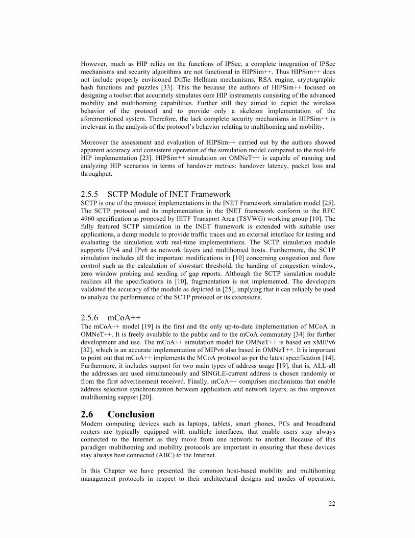
22
However, much as HIP relies on the functions of IPSec, a complete integration of IPSec mechanisms and security algorithms are not functional in HIPSim++. Thus HIPSim++ does not include properly envisioned Diffie–Hellman mechanisms, RSA engine, cryptographic hash functions and puzzles [33]. This the because the authors of HIPSim++ focused on designing a toolset that accurately simulates core HIP instruments consisting of the advanced mobility and multihoming capabilities. Further still they aimed to depict the wireless behavior of the protocol and to provide only a skeleton implementation of the aforementioned system. Therefore, the lack complete security mechanisms in HIPSim++ is irrelevant in the analysis of the protocol’s behavior relating to multihoming and mobility. Moreover the assessment and evaluation of HIPSim++ carried out by the authors showed apparent accuracy and consistent operation of the simulation model compared to the real-life HIP implementation [23]. HIPSim++ simulation on OMNeT++ is capable of running and analyzing HIP scenarios in terms of handover metrics: handover latency, packet loss and throughput.
2.5.5 SCTP Module of INET Framework SCTP is one of the protocol implementations in the INET Framework simulation model [25]. The SCTP protocol and its implementation in the INET framework conform to the RFC 4960 specification as proposed by IETF Transport Area (TSVWG) working group [10]. The fully featured SCTP simulation in the INET framework is extended with suitable user applications, a dump module to provide traffic traces and an external interface for testing and evaluating the simulation with real-time implementations. The SCTP simulation module supports IPv4 and IPv6 as network layers and multihomed hosts. Furthermore, the SCTP simulation includes all the important modifications in [10] concerning congestion and flow control such as the calculation of slowstart threshold, the handing of congestion window, zero window probing and sending of gap reports. Although the SCTP simulation module realizes all the specifications in [10], fragmentation is not implemented. The developers validated the accuracy of the module as depicted in [25], implying that it can reliably be used to analyze the performance of the SCTP protocol or its extensions.
2.5.6 mCoA++ The mCoA++ model [19] is the first and the only up-to-date implementation of MCoA in OMNeT++. It is freely available to the public and to the mCoA community [34] for further development and use. The mCoA++ simulation model for OMNeT++ is based on xMIPv6 [32], which is an accurate implementation of MIPv6 also based in OMNeT++. It is important to point out that mCoA++ implements the MCoA protocol as per the latest specification [14]. Furthermore, it includes support for two main types of address usage [19], that is, ALL-all the addresses are used simultaneously and SINGLE-current address is chosen randomly or from the first advertisement received. Finally, mCoA++ comprises mechanisms that enable address selection synchronization between application and network layers, as this improves multihoming support [20].
2.6 Conclusion Modern computing devices such as laptops, tablets, smart phones, PCs and broadband routers are typically equipped with multiple interfaces, that enable users stay always connected to the Internet as they move from one network to another. Because of this paradigm multihoming and mobility protocols are important in ensuring that these devices stay always best connected (ABC) to the Internet. In this Chapter we have presented the common host-based mobility and multihoming management protocols in respect to their architectural designs and modes of operation.

23
Moreover we have discussed how different protocols can be integrated in order to realize both mobility and multihoming. Furthermore, an overview of OMNeT++ simulation platform and an outline of the relevant simulation protocol models have been tackled. Our objective was to thoroughly review the prominent multihoming and mobility protocols and corresponding implementations, which has been achieved. The next Chapter discusses the methods used to compare and test the performance of the identified multihoming and mobility protocols and solutions.

24
25
3 QUALITATIVE AND QUANTITATIVE ANALYSIS
3.1 Introduction This chapter presents all the activities geared towards comparing the multihoming and mobility management protocols and corresponding implementations, which were discussed in the previous chapter, in the IPv6 heterogeneous wireless environment. Based on this analysis, we aim to identify the best suitable framework that supports both multihoming and mobility. It discusses the two main comparison methods, comparative qualitative framework and comparative quantitative framework. The feature comparison based on mobility and multihoming criteria is presented in the qualitative comparison whereas the simulation of protocol performance is described in the quantitative comparison. Following the qualitative and quantitative analysis stated here below, the project progressed to presentation and analysis of simulation results and then documentation.
3.2 Comparative Qualitative Framework In this section we present a qualitative comparison for the main characteristics of the studied multihoming and mobility management protocols. We focus on some of the host-based multihoming and mobility protocols/solutions which include: MIPv6, MCoA, SCTP, mSCTP, HIP, SHIM6 and MIPSHIM6. Host-based protocols are those protocols that have to be installed in the protocol stack of both the mobile node and the relevant network nodes. Section 3.2.1 deals with the comparative analysis of mobility protocols (see Table 1) whereas section 3.2.2 tackles the comparative analysis of multihoming protocols (see table 2). Finally, section 3.2.3 summarizes the benefits and drawbacks of the evaluated protocols and solutions as shown in Table 3. Based on our qualitative framework, we discuss and compare relevant evaluation characteristics of the studied mobility and multihoming protocols/solutions as follows: Protocol layer: refers to the layer of the protocol stack of the OSI reference model in which the varieties of multihoming and mobility protocols operate. Approach: classified into whether they split the Identifier from the Locator or not. Session Survivability Identifier: refers to the preservation of end-entity on sessions from path failure or mobility events. It highlights the type of identifier (e.g., HI, IP address) that provides session continuity transparently to upper-layers protocols, for both multihoming and mobility protocols/solutions. Required architectural components: refer to the additional nodes required in the network infrastructure as well as the associated modifications necessary on various nodes. Route Optimization: refers to the direct communication between the MN and CN without help from additional network elements. Handover Management: concerns about maintaining the MN’s connection as it continues to move and change its point of attachment over the network. Location Management: is used to identify the current location of MNs and also to keep track of their location changes as they move on. Security: refers to the measures taken by the protocols to protect data and signaling information against various security threats. Signaling overhead: the amount of signaling messages needed to perform the mobility management procedure during handover. This affects the performance of the mobility protocol as well as the available network capacity. Our definition of signaling overhead only considers the number of messages as opposed to the size of messages/packets.

26
Simultaneous movement of nodes: also known as the double jump, refers to the case where both communicating peers simultaneously execute an L3 handover and get attached to a new access network. Backward compatibility with IPv4: refers to the seamless operation of the IPv6 protocol implementations with the existing IPv4 infrastructure. In addition to the above characteristic features, multihoming includes a set of design goals, which we have classified as follows: Load Sharing (Flow Distribution): refers to the simultaneous use of multiple interfaces/paths in order to improve throughput. This allows traffic to be shared over several interfaces thereby achieving load balancing or even choosing the most suitable connections according to some preferences. Path Exploration: is classified into parallel or serially, and it refers to the mechanism used the monitor the alternative paths/addresses. Signaling overhead: during rehoming/link failure is the amount of signaling messages needed to perform fault recovery during when the MN switches communications from the faulty link to the new link, in order to achieve resilience against failures. Fault tolerance/Resilience: refers to the ability to detect network or link failure and recover from it.

27
3.2.1 Q
ualitative Com
parison of Mobility Protocols
Table 1: A com
parative analysis of various mobility protocols and solutions
Mobility C
riteria m
SCT
P H
IP M
IPv6 M
IPSHIM
6
Protocol layer L4 (Transport Layer)
HIP Layer (B
etween L3 and L4)
L3 (Netw
ork Layer) L3 (N
etwork Layer)
Session Survivability
Identifier Session continuity is provided by the SC
TP port Session continuity is provided by use of H
I Session continuity provided by use of H
A
Session continuity provided by use of HA
Required
architectural com
ponents The M
N and the fixed host m
ust both be
equipped w
ith netw
ork stacks
supporting Mobile SC
TP. The
current m
SCTP
specification [26] only considers a scenario w
here the M
N initiates an SC
TP association w
ith a fixed server (single-homed),
thus, limited flexibility.
HIP
DN
S server,
HIP
rendezvous server. M
N and C
N should be equipped w
ith H
IP implem
entations.
Hom
e Agent
Hom
e Agent
MN
and CN
should be equipped with
MIPShim
6 implem
entations.
Route O
ptimization
Supported Intrinsically
provides the
Route
Optim
ization w
ithout using
any additional
Binding
Update
procedures [26].
Supported
Supported B
inding update and return routability procedure needed [17].
Supported It replaces the M
IPv6 RO
with a lighter
and efficient SHIM
6 RO
mechanism
Handover M
anagement
Reactive
method
(hard handover)
handover procedure
is initiated after the MN
attaches to the new
location [35]. Proactive
method
(soft handover)
uses predictive
information to establish a data
forwarding
path before
the M
N’s m
ovement [35].
Supported U
ses the proactive method
Supported U
ses the reactive method
Supported U
ses the reactive method
Supported U
ses the reactive method

28
Mobility C
riteria m
SCT
P H
IP M
IPv6 M
IPSHIM
6
Location M
anagement
Not Supported
mSC
TP needs to be used along with a
location managem
ent scheme such as
Mobile IP or SIP.
Supported IP addresses act as locators. W
hen a host moves to another address,
it notifies its peer of the new address
by sending a HIP U
PDA
TE packet containing a LO
CA
TOR
parameter.
Supported U
ses the binding update messages, in
which M
N has to inform
its current location (C
oA) to its H
A.
Supported
U
ses the binding update messages, in
which
MN
has
to inform
its
current location (C
oA) to its H
A.
Security It ensures authentication of A
ddress C
onfiguration C
hange (A
SCO
NF)
chunks exchanged between the peers,
during mSC
TP handover. A
uthenticated C
hunks for
SCTP
allows
an SC
TP sender
to sign
chunks using a shared key between
the sender
and receiver
and also
provides a mechanism
for deriving a shared key for each association.
The connection establishment is w
ell authenticated;
the procedure
establishes Security Associations for a
secure connection with IPsec ESP.
HIP also provides a secure m
eans of updating a host's IP address via H
IP U
PDA
TE packets
by using
cryptographic verification
of the
sender.
The MN
and HA
must use an IPsec
security association
to protect
the integrity
and authenticity
of the
Binding
Updates
and A
cknowledgem
ents. The
BU
s to
CN
s are
protected by
return routability
procedure, w
hich assures that the right M
N is sending the
message.
The CN
s use secret keys, “node keys”.
The Shim
6 protocol
enforces secure
comm
unication by using both CG
A and
HB
A
addresses. The
MIPv6
protocol secures the update of the binding cache of its correspondent peers through the return routability procedure.
Signaling overhead
during handover
Low
Consists of at least four m
essages exchanged betw
een the MN
and fixed host,
including tw
o A
SCO
NF
and tw
o ASC
ON
F-AC
K packets.
Low
Consists
of three
UPD
ATE
packet m
essages, containing the LOC
ATO
R
parameter
High
It consists of at least two m
essages, BU
and B
A exchanged betw
een the MN
and H
A.
For route optimization, it includes at
least six messages i.e., tw
o BU
s, two
BA
s, HoT, C
oT, HoTi and C
oTi.
High
Consists
of at
least six
messages
exchanged between the M
N, H
A and C
N,
for a successfully handover.

29
Mobility C
riteria m
SCT
P H
IP M
IPv6 M
IPSHIM
6
Simultaneous
movem
ent of
nodes N
ot supported R
equires one of the hosts to be fixed.
Supported A
chieved by
using a
rendezvous server.
The rendezvous
server im
proves the reachability of mobile
nodes by registering their HIT-to-IP
address mappings.
Supported A
chieved by
routing the
mobility
header messages via the M
N’s hom
e agent and to the peer’s hom
e address, if it is also m
obile.
Supported A
chieved by routing the mobility header
messages via the M
N’s hom
e agent and to the peer’s hom
e address, if it is also m
obile.
Backw
ard compatibility w
ith IPv4
Supported The usage scenarios for SC
TP with
MIPv6 are sim
ilar to those for SCTP
with M
IPv4.
Supported H
osts can easily have both the current IPv4 and the new
IPv6 addresses.
Not supported
Built for strictly IPv6 nodes.
Not supported
Built for strictly IPv6 nodes.
3.2.2 Q
ualitative Com
parison of Multihom
ing Protocols
Table 2: A com
parative analysis of multihom
ing protocols and solutions
Multihom
ing Criteria
SCT
P SH
IM6
HIP
MC
oA
MIPSH
IM6
Protocol layer L4
L3 H
IP Layer (Betw
een L3 and L4) L3
L3
Session Survivability
Identifier Supported The
SCTP
port provides
session continuity.
Supported Session continuity is provided by
use of
ULID
, w
hich is
CG
A or H
BA
IP address.
Supported Session continuity provided by use of H
I.
Supported Session
continuity provided
by use of HA
.
Supported Session continuity provided by use of H
A.

30
Multihom
ing Criteria
SCT
P SH
IM6
HIP
MC
oA
MIPSH
IM6
Required
architectural com
ponents Tw
o SCTP endpoints
The endpoints should support m
ultiple interfaces/addresses.
Initiator and Responder w
hich support
multiple
interfaces and/or addresses Initiator and R
esponder must
be equipped
with
Shim6
implem
entations.
HIP
DN
S server,
HIP
rendezvous server M
N and C
N m
ust be equipped w
ith HIP im
plementations.
Hom
e Agent
Hom
e A
gent m
ust support
multiple binding cache entries
MN
should support creation of
multiple
IP address
bindings/registrations.
Hom
e Agent
MN
and CN
must be equipped
with
MIPShim
6 im
plementations.
Fault tolerance/Resilience
Supported Fault tolerance is obtained by default
when
supporting m
ultihoming, w
hich operates by m
aintaining one primary
path and
one or
more
alternative paths.
Supported
Shim6 uses the R
eachability Protocol
(REA
P) to
detect failures and to recover from
them
.
Supported Fault
tolerance for
a m
ultihomed host is achieved by
availability of
multiple
addresses at the HIP layer as
alternative locators in case of failure.
Supported Fault tolerance for a M
N is
achieved by
registering and
binding m
ultiple care-of
addresses w
ith the
home
address at a time. In case of
failure on
one link,
comm
unication is
still m
aintained on the alternative C
oA.
Supported M
akes use of the Shim6 failure
detection and
recovery capabilities.
Load
Sharing (Flow
D
istribution) N
ot supported Supported D
ifferent connections
to a
host can use different locators of a host.
Not supported
Supported C
an separate a flow betw
een m
ultiple points of attachment
simultaneously
Not supported
Path Exploration
Supported Parallel A
n SC
TP endpoint
sends H
EAR
TBEA
T m
essages to
probe the
reachability of
alternative destination
addresses defined
in the
Supported Serially W
henever there is outgoing traffic but no incom
ing return traffic or keepalive m
essages, there m
ust be failure, at which
point the
locator pair
Supported Parallel W
henever there is decreasing or no
received signal
strength indication
(RSSI)
on one
interface connection, there must
be failure, at which point the
Supported Parallel W
henever there is decreasing or no R
SSI on one interface connection,
there m
ust be
failure, at which point the path
exploration is
performed
on
Supported Serially It uses the R
EAP protocol of
Shim6 to detect failures on the
end-to-end path and also to find alternative addresses that could still allow
comm
unication, by
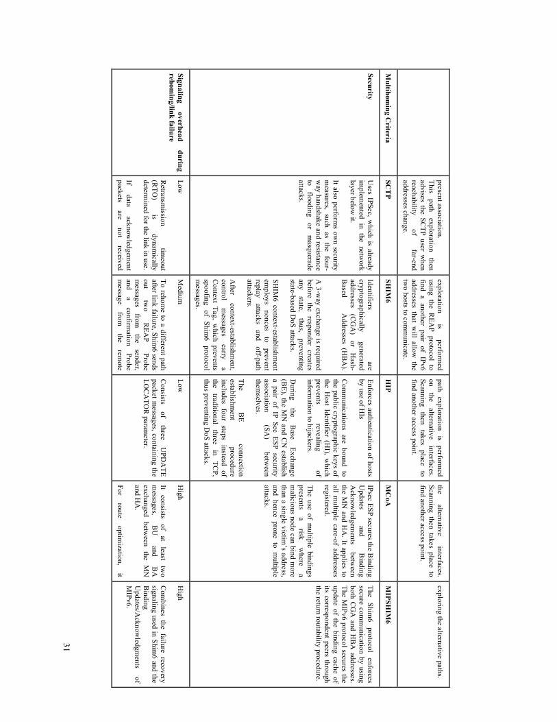
31
present association. This
path exploration
then advises the SC
TP user when
reachability of
far-end addresses change.
exploration is
performed
using the REA
P protocol to find a another pair of IPv6 addresses that w
ill allow the
two hosts to com
municate.
path exploration
is perform
ed on
the alternative
interfaces. Scanning
then takes
place to
find another access point.
the alternative
interfaces. Scanning then takes place to find another access point.
exploring the alternative paths.
Multihom
ing Criteria
SCT
P SH
IM6
HIP
MC
oA
MIPSH
IM6
Security U
ses IPSec, which is already
implem
ented in the network
layer below it.
It also performs ow
n security m
easures, such as the four-w
ay handshake and resistance to
flooding or
masquerade
attacks.
Identifiers are
cryptographically generated
addresses (C
GA
) or
Hash-
Based A
ddresses (HB
A).
A 3-w
ay exchange is required before the responder creates any
state, thus,
preventing state-based D
oS attacks. SH
IM6 context-establishm
ent em
ploys nonces
to prevent
replay attacks
and off-path
attackers. A
fter context-establishm
ent, control
messages
carry a
Context Tag, w
hich prevents spoofing of Shim
6 protocol m
essages.
Enforces authentication of hosts by use of H
Is
C
omm
unications are bound to the public cryptographic keys of the H
ost Identifier (HI), w
hich prevents
revealing of
information to hijackers.
During
the B
ase Exchange
(BE), the M
N and C
N establish
a pair of IP Sec ESP security association
(SA)
between
themselves.
The B
E connection
establishment
procedure includes four steps instead of the
traditional three
in TC
P, thus preventing D
oS attacks.
IPsec ESP secures the Binding
Updates
and B
inding A
cknowledgem
ents betw
een the M
N and H
A. It applies to
all multiple care-of addresses
registered. The use of m
ultiple bindings presents
a risk
where
a m
alicious node can bind more
than a single victim’s address,
and hence prone to multiple
attacks.
The Shim
6 protocol
enforces secure com
munication by using
both CG
A and H
BA
addresses. The M
IPv6 protocol secures the update of the binding cache of its correspondent peers through the return routability procedure.
Signaling overhead
during rehom
ing/link failure Low
R
etransmission
timeout
(RTO
) is
dynamically
determined for the link in use.
If data
acknowledgem
ent packets
are not
received
Medium
To rehom
e to a different path after link failure, Shim
6 sends out
two
REA
P Probe
messages
from
the sender,
and a
confirmation
Probe m
essage from
the
remote
Low
Consists
of three
UPD
ATE
packet messages, containing the
LOC
ATO
R param
eter.
High
It consists
of at
least tw
o m
essages, B
U
and B
A
exchanged between the M
N
and HA
. For
route optim
ization, it
High
Com
bines the failure recovery signaling used in Shim
6 and the B
inding U
pdates/Acknow
ledgments
of M
IPv6.
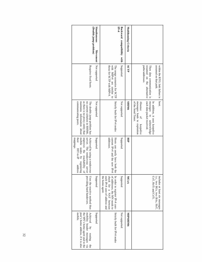
32
within the R
TO, link failure is
assumed on that path.
Then data comm
unication is resum
ed on
the alternative
paths/addresses.
host. In addition, it uses keepalive m
essages to
acknowledge
each data packet received. A
bsence of
keepalive m
essages leads to expiration of the Send Tim
er.
includes at least six messages
i.e., two B
Us, tw
o BA
s, HoT,
CoT, H
oTi and CoTi.
Multihom
ing Criteria
SCT
P SH
IM6
HIP
MC
oA
MIPSH
IM6
Backw
ard compatibility w
ith IPv4
Supported The usage scenarios for SC
TP w
ith M
IPv6 are
similar
to those for SC
TP with M
IPv4.
Not supported
Strictly built for IPv6 nodes
Supported H
osts can easily have both the current IPv4 and the new
IPv6 addresses.
Supported In order to register IPv4 care-of addresses, the M
N needs to
check for
a N
AT
between
each IPv4 care-of address and the hom
e agent.
Not supported
Strictly built for IPv6 nodes
Simultaneous
Movem
ent (D
ouble jump problem
) N
ot supported R
equires fixed hosts.
Not supported
The double jump problem
has no current solution in SH
IM6,
as there is no proxy entity that m
aintains inform
ation about
comm
unicating peers.
Supported A
chieved by using a rendezvous server. The rendezvous server im
proves the
reachability of
mobile
nodes by
registering their
HIT-to-IP
address m
appings.
Supported U
ses the reactive method thus
providing hard handovers.
Supported A
chieved by
routing the
mobility
header m
essages via
the MN
’s home agent and to the
peer’s home address, if it is also
mobile.

33
3.2.3 O
verview of the Studied M
ultihoming and M
obility Strategies Table 3: A
summ
ary of the studied multihom
ing and mobility strategies in term
s of their benefits and drawbacks
Protocol A
pproach/Aim
Pros/B
enefits C
ons/Draw
backs
MIPv6
Mobility m
anagement
Locator/Identity split The locator can be either a H
oA
or a CoA
. The identifier is the H
oA
Com
patible w
ith the
existing TC
P/IP stack
since it
doesn’t introduce new
layers. Scalable solution if C
N supports M
IPv6.
Requires IPv6 netw
ork, which presents backw
ard compatibility issues
with IPv4.
Needs addition of third entity in the infrastructure, H
ome A
gent The H
ome A
gent is a single-point of failure. Suffers from
long handover delay, packet loss, and signaling overhead. H
as some open security issues, for exam
ple the return routability procedure is not very secure [13] [17].
MC
oA
Mobility
and m
ultihoming
managem
ent Locator/Identifier split The locator can be either a H
oA
or a CoA
. The identifier is the H
oA
Com
patible w
ith the
existing TC
P/IP stack
since it
doesn’t introduce new
layers. B
ackward com
patible with IPv4.
Improved m
ultihoming support enabling load sharing and increased
resilience to failures. O
vercomes the lim
itation of MIPv6 by endorsing registration of
multiple addresses.
Has a lim
ited failure detection support, as only the failure between the
MN
and the HA
can be detected. Thus, it cannot provide a full fault-tolerant com
munication support.
Lacks a specification on how m
ultiple registered addresses can be used. For instance, if the addresses can be used sim
ultaneously, or if an address is chosen based on the link characteristics. H
as open security issues due to the risks associated with m
ultiple bindings [14].
SCT
P M
ultihoming m
anagement
Locator/Identity split The locator is the IP address The identifier is the SC
TP port
Provides the
built-in support
for m
ultihomed
endpoints and
inherent route optimization.
Does
not suffer
from
undesired end-to-end
latency w
hen readdressing is rapid.
Has better reliability in case of netw
ork failures.
R
equires very
little infrastructure
change since
there is
no dependence on the third device.
SCTP
was
originally designed
for w
ired nodes
and thus
it has
performance problem
s in wireless environm
ent. In case of IPv6 netw
ork, if a peer lists an unreachable IPv6 address (i.e., link-local or site-local) to a peer that has no connectivity to that address, then an association could be broken dow
n.
It doesn’t have the location managem
ent function, and it depends on other layers for location m
anagement, such as D
ynamic D
NS, M
IP, etc. Incom
patible with all old applications.

34
Protocol A
pproach/Aim
Pros/B
enefits C
ons/Draw
backs
mSC
TP
Mobility
and m
ultihoming
managem
ent Locator/Identity split The locator is the IP address The identifier is the SC
TP port
Provides handover managem
ent without the help of routers/agents.
Intrinsically supports Route O
ptimization.
Has low
signaling overhead as it switches connections directly
between endpoints.
There is no deployment of additional devices and doesn’t require
changes to routers.
R
equires very little infrastructure change.
Supports seamless soft handovers and m
inimization of packet loss.
Does not address the case w
here two m
obile nodes are comm
unicating. It is short of the location m
anagement function, and it depends on other
layers for location managem
ent, as in Dynam
ic DN
S, MIP, etc.
Incom
patible with all old applications.
The support of seamless handover is only a draft, and therefore m
ore w
ork needs to be done in the testing and implem
entation of this option to m
ake it work as expected.
HIP
Mobility
and m
ultihoming
managem
ent Locator/Identifier
split
The locator is the IP address The
identifier is
the H
IP H
ost Identity (H
I).
Provides integrated mobility, m
ultihoming (ubiquitous access and
reliability), and security support. Im
proved supported for the QoS of real-tim
e applications or time-
sensitive data.
B
etter handover performance because of low
signaling overhead. Enhanced end-to-end security.
IPv4/v6 interoperability, backw
ards compatible and deployable in
parallel to the existing stack.
R
equires no changes to the routing infrastructure or to the typical user-level applications.
It introduces a new H
IP layer to a well established and traditional
Internet architecture which increases data traffic and im
plementation
complexity [13]. D
eployment is costly.
Needs change of the operating system
kernel as well as m
odifications of the endpoints.
Em
ploys RV
S for location managem
ent, so it needs the addition of a third device.
New
layer solutions of HIP m
ust define a new A
PI for the HI, w
hich requires m
odification of current applications.
Heavy
computations
that are
required in
the establishm
ent of
connections, present a problem for m
obile devices with lim
ited CPU
pow
er, and thus leading to a slower connection establishm
ent.

35
Protocol A
pproach/Aim
Pros/B
enefits C
ons/Draw
backs
SHIM
6 M
ultihoming m
anagement
Locator/Identifier split The
locator is
the IP
address
The
identifier, U
LID,
is a
topologically valid IP address that is set during the Shim
6 session.
The Shim layer is easily integrated into the existing TC
P/IP stack SH
IM6 com
patible hosts can comm
unicate with other nodes that
do not implem
ent it. Thus, easily deployable in the current Internet. Enhanced failure detection m
echanism.
Good security support.
It has built-in multihom
ing support.
Lacks mobility support and it has the double jum
p problem
Absence of m
otion detection system.
High signaling overhead w
hen there are a large number of Shim
6 hosts due to the increased probe m
essages.
MIPSH
IM6
Mobility
and m
ultihoming
managem
ent Locator/Identifier split This locator can be either a H
oA
or a CoA
. The identifier, U
LID, is H
oA by
definition
Can detect any failure in the used path as it uses Shim
6 failure detection and recovery capabilities. D
oes not require modification of M
IPv6 and SHIM
6 protocol m
essages in order to provide fault tolerance. The proposed architecture overcom
es the limitations of M
IPv6 and SH
IM6.
Reduced com
plexity of the solution, because it minim
izes the changes required to available protocols. C
apable of supporting failure of the Hom
e Agent.
Solves the double jump problem
of SHIM
6
It is just a proposal, and therefore more w
ork need to be done in the test and im
plementation of this solution to m
ake it work as expected.

36
3.3 Comparative Quantitative Framework The goal of comparative quantitative analysis in this project is to evaluate the performance of multihoming and mobility protocols discussed in the qualitative comparison above, and to identify the most suitable protocol that supports both mobility and multihoming management. Quantitative analysis in scientific study can be performed through implementations, mathematical modeling, and simulations among others. In the content of this research, an implementation is a realization or execution of a protocol specification. Employing implementations is beneficial as they provide realistic functionalities and support thus, leading to a series of well-founded results. However, the implementation method is very expensive and time consuming. Mathematical modeling is representation of a system by mathematical concepts. Using mathematical analysis is advantageous as it allows scientists to formulate hypothesis and notice patterns in the developed system. On the other hand, it’s hard to find a balance between the accuracy and simplicity of a model. Finally, simulation involves the process of imitating the operation of a real-world system or process. Simulations are quite useful in studying the characteristics and behaviors of model, in a simplified and a cost-effective way. However, simulations can be overly simplified such that some core characteristics may be missing. In our research, we carried out the quantitative analysis through simulations on OMNeT++. Given the complexity of mathematical modeling and the cost of realizing implementations of the protocols within our scope of study, it was a good trade-off to instead evaluate the protocols by simulations. Therefore, our comparative quantitative analysis focused on the protocols: MIPv6, MCoA, HIP and SCTP. The main reason for the choice of these protocols is that they already had available simulation models/modules on the OMNeT++ software platform, thus, we could readily perform quantitative analysis by simulation on these protocols. Moreover, these protocols exhibited good performance qualities based on the qualitative analysis in section 3.2 above, and therefore one of them was capable of being the best suitable protocol that would support mobility and/or multihoming efficiently. Accordingly, our simulation quantitative analysis focused on the following performance metrics: rehoming time (for multihoming) and handover latency (for mobility). The main reason for choosing them is that simulation measurements and statistics from these metrics could be reliably collected on OMNeT++ simulation tool. Furthermore these metrics are able to show the performance behavior of the identified multihoming and mobility protocols.
3.3.1 Relevant Simulation Metrics Handover latency and rehoming time metrics is the set of recorded measures that we used to evaluate the overall behavior the studied protocols. The protocols we investigated in the simulations in OMNeT++ are the following: multihoming protocols (HIP, MCoA, SCTP) and mobility protocols (HIP, MIPv6). Handover latency This metric is interesting because of the movement of a MN between two attachment points, which involves changes of the access point at the link layer and consequently, possible routing changes at the IP layer. Handover latency is defined as the time interval starting when the MN leaves the old access point and ending when the communication is resumed on the new access point. During this period the MN is unable to receive packets. Packets in transit to the MN are likely dropped which may lead to disruption in communication. MIPv6 handover latency We define the overall MIPv6 handover latency as the elapsed time between the moment when the MN disassociates from the old access point (now scanning for new access point) to the instant when the MN receives the binding acknowledgement (BA) message from the CN.

37
This metric is composed of Layer 2 (L2) handover delay, router discovery delay, duplicate address detection delay, home registration delay, return routability delay and correspondent node registration delay [32] [17]. HIP handover latency We define the overall HIP handover latency as the time elapsed from the moment when the MN disassociates from the old access point and until the MN sends out the third UPDATE packet while connected to the new access point. The HIP node is ready to send data while the third UPDATE packet is processed. This latency consists of four parts. First the mobile node performs L2 handover, which is dependent on the WLAN AP and WLAN NIC hardware performance. Second the MN carries out movement detection by soliciting for router advertisements. Third the MN configures its new IPv6 address by means of stateless auto-configuration using RAs sent by the routers. Finally the HIP implementation handles the IP address change by sending out UPDATE messages. Rehoming time Hosts with multiple network interfaces have the capability to connect to different networks. For such multihomed hosts, rehoming takes place after an outage has been detected or a better path has been identified, thereby diverting existing sessions from one path to another. Rehoming time is therefore defined as the time elapsed when switching the communication flows from one interface/address to another. HIP rehoming time For a multihomed mobile node with two interfaces, the onset of rehoming is triggered when the MN comes out of range of the old access point, which is connected through the first interface. We therefore define the overall HIP rehoming time as the time interval from when the MN starts scanning the new access point on the second interface until it sends out the third UPDATE packet while connected to the new access point. This definition of HIP rehoming time includes L2 handover, configuration of new IPv6 address and HIP update message procedures. This metric accurately measures the time to recover from a path failure. MCoA rehoming time Multihoming in MCoA aims to distribute flows over interfaces, when a MN is multihomed. When MN detects a signal from a new access point (presence of another network), it immediately sets up a connection with the new access point via the second interface (new address) and then distributes the flows between the old and new access points. We define the overall MCoA rehoming time as the time elapsed when the MN starts scanning for the new access point via the second interface to the time when the MN receives the BA. As soon as the BA is received, the mobile node is ready to start distributing some of its flows to the second interface, and thus leading to improved performance. This definition of MCoA rehoming time consists of L2 handover, configuration the new of IPv6 address and MCoA signalling procedures. SCTP rehoming time Our simulation considered SCTP for fixed hosts because SCTP does not have mobility support and also its ADDIP extension [26], mSCTP, is not yet available in OMNeT++ [30]. Therefore, we only tested the multihoming ability of SCTP for the transfer of data between two fixed hosts. The hosts are multihomed since they simultaneously use two addresses (with two interfaces); one for the primary path while the other is for the alternative path. The rehoming time in this case is defined as the time elapsed between the instant when a failure occurs on the primary path until the moment when data is exchanged on the alternative path.
38
Packet loss Packet loss in reference to the receiving MN is defined as the number of lost packets during the handover period. Packet loss is proportional to handover latency (for the mobility case) and rehoming time (for the multihoming case). In our simulations, we configured the same simulation parameters and conditions over the simulation cases such as the number of mobile hosts, speed of the MN, the mobility model, RA interval, physical channel parameters, NIC settings and the data rate channel. Consequently, the resulting packet loss was directly linked to handover latency and rehoming time, leaving other factors constant. Therefore, the packet loss metric was not considered in our simulations, leaving the focus on handover latency and rehoming time.
3.3.2 Simulation Requirements System
• Ubuntu 11.10 operating system • Running kernel version: Linux version 3.0.0-32-generic-pae (buildd@aatxe) (gcc
version 4.6.1 (Ubuntu/Linaro 4.6.1-9ubuntu3)) Software
• OMNeT++ version 4.1 and 4.3 (see details of protocols models below) • Discrete event simulation platform required packages: build-essential, gcc, g++,
bison, flex, Perl, tcl-dev, tk-dev, blt, libxml2-dev, zlib1g-dev, default-jre, doxygen, graphviz, libwebkitgtk-1.0-0, openmpi-bin, libopenmpi-dev, libpcap-dev LibreOffice 3.4.4
• Calc: spreadsheets to perform statistical operation on simulation results OMNeT++ Simulation Protocol Models
• SCTP module in the INET 2.1.0 for OMNeT++ v4.3 • xMIPv6 model for OMNeT++ v4.1 • MCoA++ model for OMNeT++ v4.1 • HIPSim++ model for OMNeT++ v4.1
3.3.3 Simulation Scenarios on OMNeT++ Software Platform Consider a heterogeneous wireless environment that incorporates networks of different radio access technologies, WiFi and UMTS. The main benefit of interworking these heterogeneous networks is to enable the ABC paradigm and to ensure sessions survivability through seamless roaming. As the MN moves between these overlapping networks, it can switch communications between networks or access points using the same radio technology, e.g., from WiFi to WiFi. This process is termed as horizontal handover. Additionally, the MN can switch communication between different access technologies, e.g. from WiFi to UMTS. This feature is called vertical handover. In our simulations, horizontal handover is handled by mobility management protocols. In this case the performance metric is handover latency. On the other hand, vertical handover is handled by multihoming management protocols. Here, the performance metric is rehoming time, also known as multihoming. The selected mobility and multihoming management protocols operate on OMNeT++ simulation platform in respective models; HIP is implemented in HIPSim++, MIPv6 in xMIPv6, MCoA in MCoA++ and SCTP in INET. Five main scenarios were analyzed during our evaluation and categorized under mobility and multihoming. The mobility scenarios investigate the handover latency experienced during node movement, for the two cases when the MN is using MIPv6 or HIP respectively. Similarly, the multihoming scenarios investigate the rehoming time when the MN or fixed hosts are multihomed. In this regard, scenarios consider cases when the MN is using HIP or MCoA and when fixed hosts are using SCTP.

39
Mobility Scenario for the MIPv6 and HIP simulation model The configuration of the general network composition is seen in Figure 11. In this mobility scenario the MN moves from the home network towards the foreign/visited network at a constant speed. A CN connecting to the core router, acts as server for the MN. The CN establishes a connection with the MN, and sends ICMP Ping requests. The MN then acknowledges with ICMP Ping replies. As the MN moves away from the home network, the Received Signal Strength Indication (RSSI) metric value for the home access point will decrease below an acceptable threshold. This triggers scanning of currently available access points. The foreign access point is selected for attachment since it provides a stronger Received Signal Strength Indication (RSSI) value. At that point, the MN performs a handover from the old access point to the new access point in order to resume communications for the existing session.
Figure 11: Mobility scenario for both MIPv6 and HIP simulation models
The resumed reception of Ping replies after the handover demonstrates the re-establishment of connectivity between the MN and CN while the MN changes points of attachments. This scenario aims to analyze the handover latency experienced when the mobile is using HIP or MIPv6. The handover procedure consists of L2 handover, reconfiguration of IPv6 address and MIPv6 signaling operation or HIP signaling operation, depending on the protocol in use. Multihoming Scenario for the HIP and MCoA simulation model The configuration of the general network composition of multihoming case is shown in Figure 12. The scenario is similar to the one of mobility, with the main difference that the MN now has two interfaces/addresses and thus capable of multihoming. With the HIP multihoming feature, the MN is able to simultaneously connect to two access points such that in case of link failure or outage, communications are maintained over the alternative path on a different interface. The MCoA multihoming feature also ensures simultaneous connection to two access networks; however, it operates by distributing traffic flows between the home and foreign access points.

40
Figure 12: Multihoming scenario for both MCoA and HIP simulation models
In the multihoming scenarios, the multihomed MN moves from the home network towards the foreign/visited network at a constant speed. The MN is multihomed because it has two interfaces, IF_1 and IF_2, and thus capable of connecting to two different subnets simultaneously via two addresses. A CN connecting to the core router acts as a server for the MN. The CN establishes a connection with the MN, and sends ICMP Ping requests. The MN acknowledges the requests with ICMP Ping replies. Initially the MN is connected to the home access point via the first interface, IF_1. During node mobility, the MN detects a decreasing RSSI value for the attached home access point as it moves away from the home network. In case of HIP, further decrease in RSSI is interpreted as network outage or link failure, which then triggers scanning on IF_2, of the currently available access points. The scanning results into choosing the foreign access point to connect to, since it has a higher RSSI value. At that point, the MN rehomes the communication session from the old access point to the new access point, i.e., from IF_1 to IF_2. The HIP multihoming scenario therefore aims to investigate the latency occurring when the mobile node switches traffic flows from one interface/address to another, i.e., the rehoming time. The resumed reception of Ping replies after the rehoming procedure demonstrates a successful switch of interfaces while the mobile node changes points of attachments. In the case of MCoA, as the MN moves from the home network to the foreign network, it is continuously scanning on IF_2, and it immediately setups a connection with the foreign access point as soon as it detects some RSSI from this new access point. This connection is established on IF_2, so that the MN maintains two simultaneous connections over two interfaces via two different access points. At this point, the MN distributes the traffic flows between the two interfaces, IF_1 and IF_2. The MCoA multihoming scenario therefore aims to investigate the time difference when the MN starts scanning on IF_2 until the instant when traffic starts flowing through IF_2, i.e., rehoming time. The resumed reception of Ping replies from both interfaces after the rehoming procedure demonstrates a successful distribution of communication traffic between access points/ interfaces. This is in line with the operation of the mCoA++ simulation model, which always maintains the connection on IF_1 of the home network, and distributes the traffic flows through IF_2 once IF_2 is connected to a new access point.

41
Multihoming scenario for the SCTP simulation module In this section we present the scenario used to test the network fault tolerance functionality of SCTP protocol. The multihoming scenario of SCTP consists of two fixed hosts that are connected by two links via two routers in each path, as seen in Figure 13 below. The two hosts, Host_1 and Host_2, are multihomed, each having two interfaces and an IPv6 address configured on each interface. In this scenario, SCTP offers network fault tolerance through supporting of multihoming at both ends of an association. HOST_1 seeks to transmit data to HOST_2 but before communication can begin, an SCTP association is established between endpoints. During the SCTP association, HOST_1 provides HOST_2 with a list of two IP addresses, which are configured on different network interfaces, to enable network fault tolerance. The first IP address is the default address from which HOST_1 will originate SCTP packets whereas the second IP address provides an alternative path through which HOST_1 can be reached in case of failure.
Figure 13: Multihoming scenario for the SCTP simulation module
Initially, all data traffic exchanged between these hosts goes through the primary path. At a certain time, the link connecting Router_1 and the Internet over the primary path fails; this is detected by SCTP, which takes action such that the communication is rehomed to the alternative path. The SCTP multihoming scenario therefore aims to investigate the time difference from the instant of link failure on the primary path to the time when data communication is resumed on the alternative path, i.e. rehoming time.
3.3.4 Modification and Configuration of Relevant Models SCTP The SCTP module in INET2.1 model works well with IPv4-based networks. Unfortunately, it was not fully implemented to be compatible with IPv6. Although the developers of this module had worked on introducing support for IPv6 in SCTP, some features pertinent to our project were not available such as configuration of IPv6 addresses and static routes and collection of statistics. Because our project was focused on IPv6-based networks, we had to make SCTP compatible with IPv6 network scenarios, and we did this by modifying the specific SCTP module classes. Configuration of static routes The most important requirement for SCTP to work is the initialization phase, in which all the nodes interfaces, IP addresses, communication routes and primary path should be configured. Static routes should be used to finish this initialization phase of SCTP, however,

42
the OMNeT++ 4.3 platform that we used provided no way of configuring IPv6 static routes. Hence our task was to develop a method of adding static routes for IPv6 networks, as follows: In the class “RoutingTable6”, we added the function “configureRouteFromXML()” and changed the function “parseXMLConfigFile()”, such that the system could read the XML routing table files. Using the information in the XML routing files, static routes are configured. The structure of the routing files was modified to also include route and routeEntry elements where routeEntry includes the following attributes: routeIface, routePrefix, routePrefixLength and routeNextHop. An example of XML routing file can be found in the Appendix. Display of IPv6 addresses and interfaces Another component that was lacking in OMNeT++ simulation platform was the capability to display IPv6 addresses on the simulation topology diagrams which made it so cumbersome for us, while working on the configurations of the interfaces for our network scenarios. We therefore fixed this issue, by modifying the functions assignAddress() of the IPv6InterfaceData class. Modification of SCTP classes to work with IPv6 Because the SCTP module in INET framework was mainly built for IPv4 networks, we had to modify most of its functions in the respective classes in order to operate on IPv6 datagrams and addresses. The specific classes in which we introduced IPv6-based modifications are the following: “SCTPServer”, “SCTP”, “SCTPAssociation” and “SCTPPathVariables”. Calculation of SCTP rehoming time In order to accurately measure rehoming time in SCTP multihoming scenario, we have to capture the time point when data traffic is resumed on the alternative path after an event of link failure on the primary path. Therefore, to locate this time point modified the routePacket() function of IPv6 class. Specifically, the lines of codes we introduced in routePacket() search for the data packets with the destination address of the alternative path, which is “2001:eeee:1::1” for our case. Moreover, we configured the simulation to terminate when all the data is transferred, at the instant when the “SCTPServer”, i.e. the application running on HOST_2, receives the message “SCTP_I_CLOSED”. xMIPv6 Calculation of MIPv6 total handover latency In our simulation, we define the total MIPv6 handover latency as the time difference between the instant when the mobile node sends out the scan request and when it gets the binding acknowledgement from the correspondent node. The scan request time was accurately measured by recording the time point, !"#$%&'(&)*+,-&, from the sendScanRequest() function of the Ieee80211AgentSTA class. Similarly, the time of reception of the Binding Acknowledgement was measured by recording the time point, !"#$%$&'$(&)$, from the processMobilityMessage() function belonging to xMIPv6 class. The MIPv6 handover latency was thus obtained as !"#$%$&'$(&)$ − !"#$%&'(&)*+,-&. The simulation was configured to automatically terminate when !"#$%$&'$(&)$ is recorded. Calculation of IPv6 address configuration delay The MN in our simulations uses IPv6 stateless auto-configuration mechanism to obtain a new IPv6 address. The IPv6 address configuration starts from the time when the MN gets a new address up to when Duplication Address Detection procedure is completed. To measure the IPv6 address configuration delay; we recorded the time point when the system generates the message “Prefix not assigned to interface” at!!"#$$%&''#''()*&$+(,&, located in IPv6NeigbourDiscovery class. In addition, we also recorded the time point when the system

43
later generates the message “DAD Timeout message received” at !"!#$%$&ℎ!"#$. Thus IPv6 address configuration delay is obtained as DADfinishTime – IPAddressAssignedTime. Calculation of L2 handover delay To obtain L2 handover delay values in our simulations, we recorded two important time points; !"#$%&'(&)*+,-&, which is the instant when the MN starts scanning, performed by the sendScanRequest() function of Ieee80211AgentSTA class. !""#$%&'%#()#(*%+,-%,. is the instant when the MN is successfully associated to the new access point and is generated by processAssociateConfirm() function of Ieee80211AgentSTA class. L2 handover delay is then obtained as !""#$%&'%#()#(*%+,-%,. − !"#$%&'(&)*+,-&. mCoA++ Calculation of MCoA rehoming time We obtained MCoA rehoming time in the multihoming scenario as the time difference when the MN sends out a scan request over IF_2 until it gets a BA on the same interface. To measure the MCoA rehoming time, we recorded the following time points: !"#$%&'(&)*+,-&, generated by the sendScanRequest() function of the Ieee80211AgentSTA class, and also !"#$%$&'$(&)$, generated by processMobilityMessage() function of xMIPv6 class. The time difference !"#$%$&'$(&)$ − !!"#$%&'(&)*+,-&, indicates MCoA rehoming time. The simulation was also configured to terminate automatically after obtaining !"#$%$&'$(&)$. Access point settings modification In order to have MCoA++ access point settings consistent with the rest of simulations models, i.e., xMIPv6 and HIPSim++, we changed the management module (mgmt) value of Ieee80211Nic module from Ieee80211Mgmt to Ieee80211MgmtAP. The NIC implements an 802.11 network interface card, and it can be configured via the mgmt parameter to operate as a mobile access point (AP), stationary access point (STA), or ad-hoc mode. HIPSim++ Calculation of total HIP handover latency In the mobility scenario, the overall HIP handover latency constitutes the time difference from when the MN starts scanning up to the moment it sends out the third UPDATE packet. HIP handover latency was therefore measured by recording the time points: !"!"#$%&$'()*+$, generated by sendScanRequest() function of the Ieee80211AgentSTA class, and !"#$%ℎ!"#$%#&'()!*( generated by the handleMsgRemoteIn() function of HipFsmBase class. We therefore obtained the total HIP handover latency as !"#$%ℎ!"#$%#&'()!*( − !!"#$%&'(&)*+,-&. Calculation of HIP rehoming time In the multihoming scenario, the HIP rehoming time is the time elapsed from the instant the MN starts scanning using IF_2 to the time it sends the third UPDATE packet while connected to the foreign access point through IF_2. In order to measure HIP rehoming time, we recorded the time point when the MN starts scanning on IF_2, !"#$%&'(&)*+,-&, generated by sendScanRequest() function of the Ieee80211AgentSTA class. And also we recorded the time point when it sends out the third UPDATE packet when connected to the new access point, !"#$%ℎ!"#$%#&'()!*(, generated by the handleMsgRemoteIn() function of HipFsmBase class. The time difference, SendThirdUpdateTime – ScanRequestTime, measured the overall HIP rehoming time. Calculation of HIP layer signaling delay The signaling delay due to HIP mechanisms for both mobility and multihoming, was measured by recording the time point when the MN sends out the first UPDATE packet, !"#$%&'()*+$,)"-&.", and also the time point when the MN sends out the third

44
UPDATE, !"#$%ℎ!"#$%#&'()!*(. HIP signalling delay was therefore obtained as !"#$%ℎ!"#$%#&'()!*( − !!"#$%&'()*+$,)"-&.".
3.3.5 Setup and Execution of Simulations Simulation of the experiments was carried on OMNeT++ using the respective protocol models. Mobility Scenario for MIPv6 The simulation network topology is shown in Figure 14 below. The simulation is done on an 850!×850! area. The simulation devices include a home agent (Home_Agent), home access point (AP_Home), mobile node (MN), foreign Access point (AP_1), foreign access router (R_1), Gateway Router (R_2), hub and a correspondent node (CN). AP_1 attaches to Home_Agent and AP_1 attaches to R_1. The areas of coverage for AP_Home and AP_1 are overlapped at the boundaries/edges to allow for the continuous connectivity to the wireless network, and there is an approximate distance of 300 meters between AP_Home and AP_1. The backbone links to R_2 are 1000Mps whereas the links between the access points and respective routers are 100Mbps Ethernet. The MN is configured with 802.11 network interface card (NIC), which forms the wireless interface for normal communication with the access points. The MN moves from the home network of AP_Home to the foreign network of AP_1 at speed of 1m/s. The background traffic is the ICMP Ping session, initiated from the CN to the MN. During the simulation, CN sends ping packets continually to the moving MN at a rate of one ping request every 50ms.
Figure 14: The simulation network topology for MIPv6 mobility scenario
The simulation investigates MN’s movement from its home network towards the visited network, and this is repeated 40 times, constituting 40 independent simulation runs, each run performing one handover. For each run, a different seed value is generated using OMNeT++’s processid, which is then fed into seed-set in the configuration file. The performance metric that is important in this simulation is handover latency, and it calculated from the output variables: !"#$%$&'$(&)$ and !"#$%&'(&)!"#$%. The studied simulation scenario is designed to provide realistic and also statistically significant results. This also allows us to compute 95% confidence intervals. Table 4 shows the summary of parameter settings configured for different elements in the simulation.
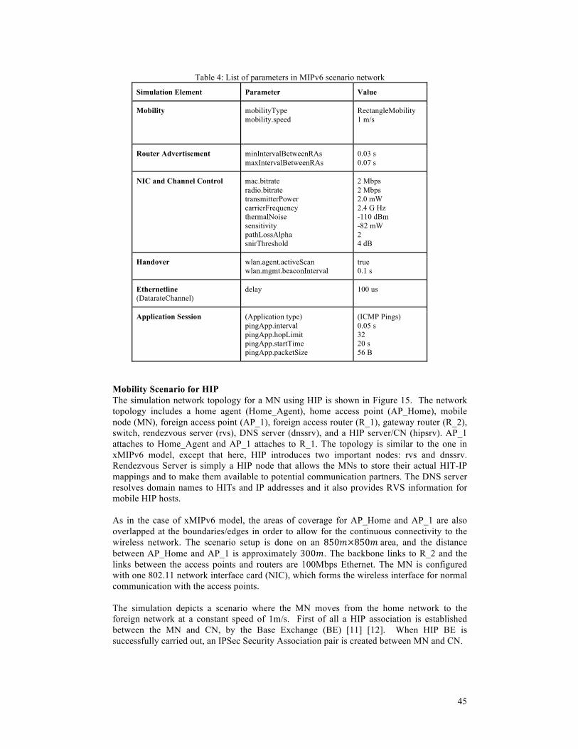
45
Table 4: List of parameters in MIPv6 scenario network
Simulation Element Parameter Value
Mobility mobilityType mobility.speed
RectangleMobility 1 m/s
Router Advertisement
minIntervalBetweenRAs maxIntervalBetweenRAs
0.03 s 0.07 s
NIC and Channel Control mac.bitrate radio.bitrate transmitterPower carrierFrequency thermalNoise sensitivity pathLossAlpha snirThreshold
2 Mbps 2 Mbps 2.0 mW 2.4 G Hz -110 dBm -82 mW 2 4 dB
Handover wlan.agent.activeScan wlan.mgmt.beaconInterval
true 0.1 s
Ethernetline (DatarateChannel)
delay 100 us
Application Session (Application type) pingApp.interval pingApp.hopLimit pingApp.startTime pingApp.packetSize
(ICMP Pings) 0.05 s 32 20 s 56 B
Mobility Scenario for HIP The simulation network topology for a MN using HIP is shown in Figure 15. The network topology includes a home agent (Home_Agent), home access point (AP_Home), mobile node (MN), foreign access point (AP_1), foreign access router (R_1), gateway router (R_2), switch, rendezvous server (rvs), DNS server (dnssrv), and a HIP server/CN (hipsrv). AP_1 attaches to Home_Agent and AP_1 attaches to R_1. The topology is similar to the one in xMIPv6 model, except that here, HIP introduces two important nodes: rvs and dnssrv. Rendezvous Server is simply a HIP node that allows the MNs to store their actual HIT-IP mappings and to make them available to potential communication partners. The DNS server resolves domain names to HITs and IP addresses and it also provides RVS information for mobile HIP hosts. As in the case of xMIPv6 model, the areas of coverage for AP_Home and AP_1 are also overlapped at the boundaries/edges in order to allow for the continuous connectivity to the wireless network. The scenario setup is done on an 850!×850!!area, and the distance between AP_Home and AP_1 is approximately 300!. The backbone links to R_2 and the links between the access points and routers are 100Mbps Ethernet. The MN is configured with one 802.11 network interface card (NIC), which forms the wireless interface for normal communication with the access points. The simulation depicts a scenario where the MN moves from the home network to the foreign network at a constant speed of 1m/s. First of all a HIP association is established between the MN and CN, by the Base Exchange (BE) [11] [12]. When HIP BE is successfully carried out, an IPSec Security Association pair is created between MN and CN.
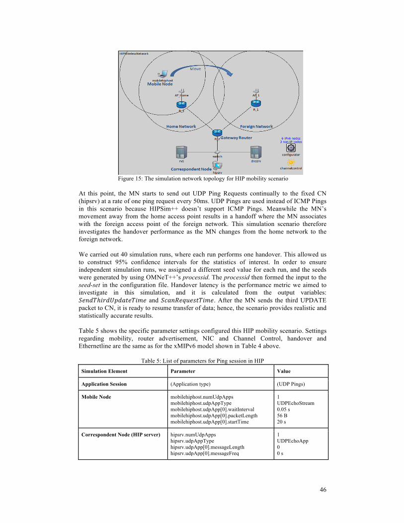
46
Figure 15: The simulation network topology for HIP mobility scenario
At this point, the MN starts to send out UDP Ping Requests continually to the fixed CN (hipsrv) at a rate of one ping request every 50ms. UDP Pings are used instead of ICMP Pings in this scenario because HIPSim++ doesn’t support ICMP Pings. Meanwhile the MN’s movement away from the home access point results in a handoff where the MN associates with the foreign access point of the foreign network. This simulation scenario therefore investigates the handover performance as the MN changes from the home network to the foreign network. We carried out 40 simulation runs, where each run performs one handover. This allowed us to construct 95% confidence intervals for the statistics of interest. In order to ensure independent simulation runs, we assigned a different seed value for each run, and the seeds were generated by using OMNeT++’s processid. The processid then formed the input to the seed-set in the configuration file. Handover latency is the performance metric we aimed to investigate in this simulation, and it is calculated from the output variables: !"#$%ℎ!"#$%#&'()!*( and !"#$%&'(&)*+,-&. After the MN sends the third UPDATE packet to CN, it is ready to resume transfer of data; hence, the scenario provides realistic and statistically accurate results. Table 5 shows the specific parameter settings configured this HIP mobility scenario. Settings regarding mobility, router advertisement, NIC and Channel Control, handover and Ethernetline are the same as for the xMIPv6 model shown in Table 4 above.
Table 5: List of parameters for Ping session in HIP
Simulation Element Parameter Value
Application Session (Application type) (UDP Pings)
Mobile Node mobilehiphost.numUdpApps mobilehiphost.udpAppType mobilehiphost.udpApp[0].waitInterval mobilehiphost.udpApp[0].packetLength mobilehiphost.udpApp[0].startTime
1 UDPEchoStream 0.05 s 56 B 20 s
Correspondent Node (HIP server) hipsrv.numUdpApps hipsrv.udpAppType hipsrv.udpApp[0].messageLength hipsrv.udpApp[0].messageFreq
1 UDPEchoApp 0 0 s

47
Multihoming Scenario for HIP This multihoming simulation setup considers failures due to handovers, which are caused by the movement of the MN when roaming between networks. As a result of network outage on the previous connection, the MN switches to a new network. Our multihoming network topology is similar to the one for the HIP mobility topology, shown in Figure 15 above. The difference is that now, two 802.11 network interface cards (NICs) are installed on the MN, i.e. IF_1 and IF_2. The simulation considers a heterogeneous network environment consisting of WiFi and UMTS networks. In this environment, the MN can connect to WiFi through IF_1 and to UMTS through IF_2. As the MN moves from the WiFi network (Home Access point) to UMTS network (Foreign access point), a UDP Ping session is established, where the MN is designated as the sender and the CN designated as the receiver. The UDP ping application settings for the MN and CN are seen in Table 5 above. The MN is moving away from the Home Access point at a constant speed of 1m/s, leading to the decrease of RSSI on IF_1, which triggers scanning on IF_2 for new access points. At a certain point, the MN switches communication sessions from IF_1 to IF_2 on the new foreign access point, as a fault tolerance mechanism dealing with network outage of WiFi connection. The MN is configured to use IPv6 stateless auto-configuration mechanism to obtain new IP addresses on its interfaces. Thus, the MN rehomes to IF_2 on the UMTS network thereby maintaining existing applications and sessions running on the MN. This multihoming simulation investigates the rehoming performance as the MN changes from WiFi to UMTS, i.e. from IF_1 to IF_2. We performed 40 series of measurements to produce a more a detailed picture on rehoming time behavior as well as to allow us to construct 95% confidence intervals for the statistics of interest. The series were independent since each run was performed with a different seed value, which enabled statistically random results. Moreover, the simulation was set up to trigger 1 rehoming event in every simulation run. The performance metric under study was rehoming time, and it was calculated from the simulation output variables: !"#$%&'(&)*+,-& on IF_2 and !"#$%ℎ!"#$%#&'()!*( from IF_2 to CN. Table 6 shows a list of parameters configured for the home access point, foreign access point, IF_1 and IF_2. The rest of simulation settings regarding Mobility, Router Advertisement, NIC and Channel Control, Handover and Ethernetline are the same as for the xMIPv6 model shown in Table 4 above.
Table 6: List of parameters for HIP multihoming scenario
Simulation Element Parameter Value
AP_Home wlan.mac.bitrate wlan.radio.bitrate wlan.radio.channelNumber
11e6 bps (WLAN) 11e6 bps 1
AP_1 wlan.mac.bitrate wlan.radio.bitrate wlan.radio.channelNumber
2.6e6 bps (UMTS) 2.6e6 bps 2
IF_1 mac.bitrate radio.bitrate agent.channelsToScan
11e6 bps 11e6 bps 1
IF_2 mac.bitrate radio.bitrate agent.channelsToScan
2.6e6 bps 2.6e6 bps 2
48
Multihoming Scenario for MCoA The MCoA multihoming network topology is similar to the one for MIPv6 mobility topology, as seen in Figure 14. The only difference is that the MCoA multihoming scenario considers a heterogeneous network environment where the MN having two interfaces, is able to simultaneously connect to two different access networks with the aim of distributing traffic flows between the two access points. We considered a heterogeneous network having two overlapping networks, WiFi and UMTS. The MN is configured with two 802.11 network interface cards (NICs) i.e. IF_1 and IF_2, and in this environment the MN can connect to WiFi through IF_1 and to UMTS through IF_2. The list of parameter settings configured for home access point (WiFi), foreign access point (UMTS), IF_1 and IF_2 are depicted in Table 6 above. In this simulation setup, both the MN and CN are running an ICMP Ping application where the CN is the sender of ICMP Ping requests while the MN is the receiver. The MN acknowledges the received Ping requests by sending out ICMP Ping replies to the CN. The MN is initially located in the WiFi network (home network) in which it is associated to AP_Home through IF_1, and it moves toward towards the UMTS network (foreign network) at a constant speed of 1m/s. Meanwhile the MN is continually scanning on IF_2 to establish if there are potential access points it can connect to in order to improve performance by simultaneously using both IF_1 and IF_2 for data communication. As the MN moves from the WiFi network to UMTS network, at a certain point it will detect an acceptable RSSI value from the UMTS access point (AP_1) resulting into association on this new access point through IF_2. At this point, the MN has two simultaneous connections, to WiFi and UMTS, over two different interfaces, IF_1 and IF_2. At this point it starts distributing the traffic flows between the two interfaces. As in the HIP and MIPv6 scenarios, the MN uses IPv6 stateless auto-configuration in order to obtain the new IP address on its interface. This simulation therefore investigates the multihoming performance as the MN uses both interfaces for traffic flow while it is connected to WiFi and UMTS. The simulation settings regarding Mobility, Router Advertisement, NIC and Channel Control, Handover and Ethernetline are the same as for the xMIPv6 model shown in Table 4 above. To obtain a detailed analysis of MCoA multihoming behaviour, we run 40 series of measurements. Each series constituted one simulation run, and the runs were independent since we employed a different seed value for each simulation run. Furthermore, we configured each simulation run to trigger 1 rehoming event, obtained at the instant when the MN starts to use both IF_1 and IF_2. Rehoming time is the performance metric we aimed to measure in this simulation, and it was calculated from the simulation output variables: !"#$%&'(&)*!"#$ on IF_2 and !"#$%$&'$(&)$ from home agent. After the MN receives the BA (!"#$%$&'$(&)$) from the home agent, traffic data flows are distributed between IF_1 and IF_2, hence, this scenario provides realistic and statistically accurate results. Multihoming Scenario for SCTP The simulation network topology for investigating the multihoming capability of SCTP protocol is shown in Figure 16. The topology includes SCTP fixed hosts; Host_1 and Host_2, and the routers; router_1, router_2, router_3 and router_4. The SCTP hosts are multihomed, since each has two interfaces and a different IPv6 address is configured on each interface. The links between routers form the core network and these are configured with data rate of 1Gbps and transmission delay of 20ms. The Ethernet connections terminating on the hosts are configured with data rate of 100Mbs and transmission delay of 10ms. The simulation setup aims to study the network fault tolerance feature of SCTP, in event of link failure on the primary path during data exchange between the hosts. We configured host_1 to transfer 10MB of data to host_2, such that host_1 acts as the client while host_2 the server. The Table 7 shows the SCTP parameter settings that we configured for the client and server.

49
Figure 16: Simulation network topology for SCTP multihoming scenario
Table 7: List of parameters for SCTP multihoming simulation setup
Simulation Element Parameter Value
host_1 numSctpApps sctpApp[0].typename sctpApp[0].startTime sctpApp[0].numRequestsPerSession sctpApp[0].requestLength
1 SCTPClient 5s 10000 1000
host_2 numSctpApps sctpApp[0].typename
1 SCTPServer
After establishment of SCTP association between endpoints, the path consisting of routers, router_1 and router_2, is designated as the primary path whereas the path having routers, router_3 and router_4, is designated as the alternative path. The initialization phase and SCTP association takes approximately 5s, after which all data communication that is exchanged between the hosts goes through the primary path. After some time, the primary path experiences link failure in the core network between routers, router_1 and router_2. The failure event occurs at a time defined by a uniform distribution between 5.3 and 7.5 seconds. This link failure is detected by SCTP, which then redirects the communication through the alternative path using a new set of addresses. The simulation therefore studies the link fault tolerance measured by the difference in time from the instant of link failure to time when data communication is resumed on the alternative path, which we call rehoming time. We performed a total of 40 simulation runs in order to capture a more detailed picture on rehoming time behavior and to construct 95% confidence intervals. We assigned each simulation run a different failure time instant, which was obtained by randomly generating values from the uniform distribution between 5.3 and 7.5, thus introducing randomness. We calculated the rehoming time from the time-stamps of the following simulation variables: DataOnAlternativePathTime and LinkFailureTime, where DataOnAlternativePathTime is the time-stamp recorded for the first data packet transmitted on the alternative path, while !"#$%&"'()*+",* is the instant of link failure on the primary path.
3.3.6 Randomness in the Simulations Randomness was an important aspect of our simulations as this enabled us to produce identically independent variables, which we used to compute the mean values and the corresponding 95% confidence intervals. For the wireless simulation scenarios, we set the RA interval in the range 0.03 and 0.07s, such that the actual value employed in each

50
simulation run was randomly selected from that range. In addition to the RA interval, we also changed the seed in each simulation run for event randomization. For the fixed simulation scenario of SCTP, randomness was introduced by using different failure time instants, which were obtained by randomly generating values from the uniform distribution between 5.3 and 7.5s.
3.4 Conclusion This chapter has presented in detail the steps taken to compare several multihoming and mobility management protocols and/or solutions in IPv6-based network. Firstly, we carried out a qualitative comparison of these protocols and/or solutions in terms of multihoming and mobility goals, benefits and drawbacks. Secondly, from the qualitative analysis we identified four suitable protocols and associated performance metrics and then quantitatively analyzed the protocols using simulations on the OMNeT++ software platform. Finally, the setup and configuration of the different simulation scenarios on the simulation platform has also been discussed. The next chapter presents a discussion of the validation and analysis of simulation results.

51
4 PRESENTATION AND ANALYSIS OF RESULTS
4.1 Introduction This chapter lays out the simulation results, obtained from the experimental scenarios carried out in Chapter 3. Diagrams, tables, graphs and results are presented where necessary to illustrate the results.
4.2 Presentation of Simulation Results Mobility simulation for MIPv6 In the MIPv6 mobility scenario, we set out to investigate the handover performance as the MN moved from the home network to foreign network. We measured the handover performance in terms of handover latency metric, !!" ,!calculated from the time-stamps of required output variables: !!" = !!"#$%$&'$(&)$ − !!"#$%&'(&)*+,-&. In addition to other output variables including L2_Handover, DAD_Delay, MIPv6_Delay, Ping drop rate, Ping round trip delays etc., the results were saved in the output scalar file and data was plotted using Microsoft Excel. Based on the 40 simulation runs, handover latency was expressed as the average of the 40-handover series. The obtained average handover latency is 3.32s, and the statistical accuracy is represented by a 95% confidence interval where the real value is within ±2.65% (marginal error) around the average. The total MIPv6 handover latency can be divided into three phases: L2 handover, IPv6 address configuration and MIPv6 signaling. Latency is produced in each phase. L2 handover delay is dependent on the WLAN AP and WLAN NIC hardware performance. IPv6 address configuration consists of router discovery delay and duplicate address detection delay. MIPv6 signaling is composed of the following delay components: home registration, return routability and CN registration. The total MIPv6 handover latency in every phase is shown in Table 8.
Table 8: Results of MIPv6 Total Handover Latency and delays in each phase
Type of Delay Average Delay (s) Percentage contribution for each phase (%)
L2 Handover Delay 0.655 19.75
IPv6 Address Configuration Delay 1.622 48.93
MIPv6 Signaling Delay 1.038 31.32
Total Handover Latency 3.315 100.00
Mobility simulation for HIP In the HIP mobility experiment, we wanted to find out the overall handover performance of the HIP protocol in terms of handover latency, studied from the point of view of a single MN that leaves its home network and enters the domain of a foreign network. The total HIP handover latency was obtained by, firstly, recording the time-stamps of output variables of interest and then calculating this value using: !!" = !!"#$%ℎ!"#$%#&'()!*( −!!"#$%&'(&)*+,-&. Using a total of 40 simulation runs, where each run performed one handover, the total handover latency was then calculated as the average sum of all the measured latencies. The total HIP handover latency obtained in this simulation setup is

52
2.266s, where the real value is within ±4.07% (marginal error) of the estimated value with a confidence interval of 95%. As in MIPv6, our definition of HIP handover latency constitutes three phases: L2 handover, IPv6 address configuration and HIP signaling. Moreover, each phase contributes to the total latency. L2 handover is a link layer specific handover delay. IPv6 address configuration involves router detection delay and duplicate address detection delay after configuration of a new IPv6 address. HIP signaling consists of the time delay for the 3 UPDATE packets. The results for the average delay accruing from the individual delay components and the total handover delay are shown in Table 9.
Table 9: Results of HIP Total Handover Latency and delays in each phase
Type of Delay Average Delay (s) Percentage contribution for each phase (%)
L2 Handover delay 0.6549 28.90
IPv6 Address Configuration Delay 1.6026 70.73
HIP Signaling Delay 0.0082 0.36
Total Handover Latency 2.2658 100.00
Multihoming simulation for MCoA In the MCoA simulation scenario, we set out to the investigate the multihoming performance of MCoA protocol in terms of rehoming time from the instant when the mobile node starts scanning on the second interface (IF_2) to the time traffic starts flowing through that interface. The rehoming time metric was measured by, firstly, recording the time-stamps of the pertinent output variables and then calculating this value using: !!" = !"#$%$&'$(&)$ − !"#$%&'(&)*+,-&. From 40 simulation runs, where each run performed one rehoming event, the total rehoming time was obtained as the average sum of all the measured runs. The simulation results from this setup produced the total rehoming time of 1.66s, within a statistical accuracy of 95% confidence interval having a marginal error of ±5.49%. The obtained rehoming time is a sum of delays from three phases: L2 handover, IPv6 address configuration and MCoA signaling. MCoA signalling includes the binding update and binding acknowledgement messages exchanged between the MN and home agent. In this simulation, MCoA rehoming time was evaluated, in addition to checking each phase of the process. The Table 10 below shows the obtained average delays from the three phases and the total rehoming time.
Table 10: Results of MCoA Rehoming Time and the delays in each phase
Type of Delay Average Delay (s) Percentage contribution for each phase (%)
L2 Handover delay 0.4043 24.42
IPv6 Address Configuration Delay 1.2459 75.26
MCoA Signaling Delay 0.0054 0.32
Total Rehoming Time 1.6555 100.00

53
It is worth mentioning that the MCoA protocol in MCoA++ was optimized to take advantage of flow distribution mechanism of multihoming. With this flow distribution feature, flows are dynamically stripped between interfaces, according to preferences with the aim of optimizing the use of bandwidth and also minimizing the effect of bottlenecks to delay-sensitive applications. Multihoming simulation for HIP To understand the behavior of multihoming performance for the HIP protocol where a MN experiences network failure as it roams between two networks, we carried out the HIP multihoming scenario on OMNeT++ using HIPSim++ simulation framework. This simulation was deployed to measure multihoming performance in terms of rehoming time metric as the MN changes from IF_1 to IF_2. In order to measure the rehoming time, we recorded the time-stamps of parameters of interest in the output scalar file. Then we calculated rehoming time, !!", using the equation !!" = !"#$%ℎ!"#$%#&'()!*( −!"#$%&'(&)*+,-&. We focused on the MN movement from the home network towards the foreign network for each simulation run. This iteration was repeated 40 times, thus producing 40 series of measurements. The total rehoming time was then calculated as the average sum of the 40 rehoming events. The total HIP rehoming time obtained is 413ms, of which the real value is within ±0.09% (marginal error) of the estimated value, represented by a 95% confidence interval. The obtained average rehoming time is a sum of delays from two phases: L2 handover and HIP signaling. L2 handover delay depends on the specific physical transport technology and NIC design. HIP signaling consists of the time delay for the 3 UPDATE packets. The table 11 below shows the obtained average delays from the two phases and the total rehoming time.
Table 11: Results of the HIP Total Rehoming time and delays in each phase
Type of Delay Average Delay (s) Percentage contribution for each phase (%)
L2 Handover delay 0.4046 98.03
HIP Signaling Delay 0.0081 1.97
Total Rehoming Time 0.4127 100.00
Multihoming simulation for SCTP In this simulation set up, our aim was to investigate the link fault tolerance in terms of rehoming time metric,!!!" , which we defined as the time difference from the time the primary link experiences failure to the time when data communication is resumed on the alternative path. We performed 40 simulation measurements, where we supplied a unique instant of link failure for each run obtained by uniform distribution between 5.3 and 7.5 seconds. In every simulation run, we recorded the time-stamp when the first packet data is transmitted on the alternative path, after link failure on the primary path. We defined rehoming as the change of communication path from primary link to alternative link, using a different interface and IP address. The total rehoming time was then calculated as the average sum of all the 40 rehoming events. From this simulation setup, we obtained the total rehoming time of 992ms, calculated with a statistical accuracy of 95% confidence interval within a marginal error of ±1.01%.

54
4.3 Interpretation and Analysis of Results In this section, we present the analysis of simulation results in which we quantitatively assess and compare the performance of the simulated protocols. The objective is to identify the protocol that efficiently manages both multihoming and mobility in terms of the simulation performance metrics. Firstly, we present the comparative performance evaluation of mobility protocols consisting of MIPv6 and HIP, in terms of the handover latency metric. Then we proceed to perform a comparative analysis of the simulated multihoming protocols, MCoA, HIP and SCTP, based on the obtained simulation results of the rehoming time. The results provide a performance evaluation of multihoming functionality in terms of rehoming time metric.
4.3.1 Mobility Protocols The Figure 17 and Table 12 depict the comparative performance evaluation of the Mobile IPv6 protocol and HIP protocol. The main performance metric that allows us to compare these mobility protocols in terms of handover performance is the overall handover latency. The lower the handover latency, the higher the mobility management performance of the protocol. The reason is that low handover latency results in low packet loss, hence having a minimum impact on real-time communication. The simulation results from the mobility scenarios show that HIP protocol has a handover latency of 2.27s compared to 3.32s for MIPv6, which means HIP shows better performance. The higher latency for MIPv6 can be explained by high signaling delay. In our experiments, MIPv6 required 1.038s to complete signaling, which is 1s higher than the associated HIP signaling delay, as already pointed out in section 4.2. In general, the fact that HIP signaling constitutes only 3 UPDATE messages exchanged between the MN and CN, unlike MIPv6 signaling that involves BU and BA message exchanges between the MN and HA in addition to the CoT, CoTi, HoT, HoTi, BU and BA messages with the CN, gives HIP a performance edge over MIPv6. Consequently, the longer latency in the case of MIPv6 results in higher packet loss compared to HIP.
Figure 17: Comparative performance evaluation of MIPv6 and HIP in terms of Handover latency
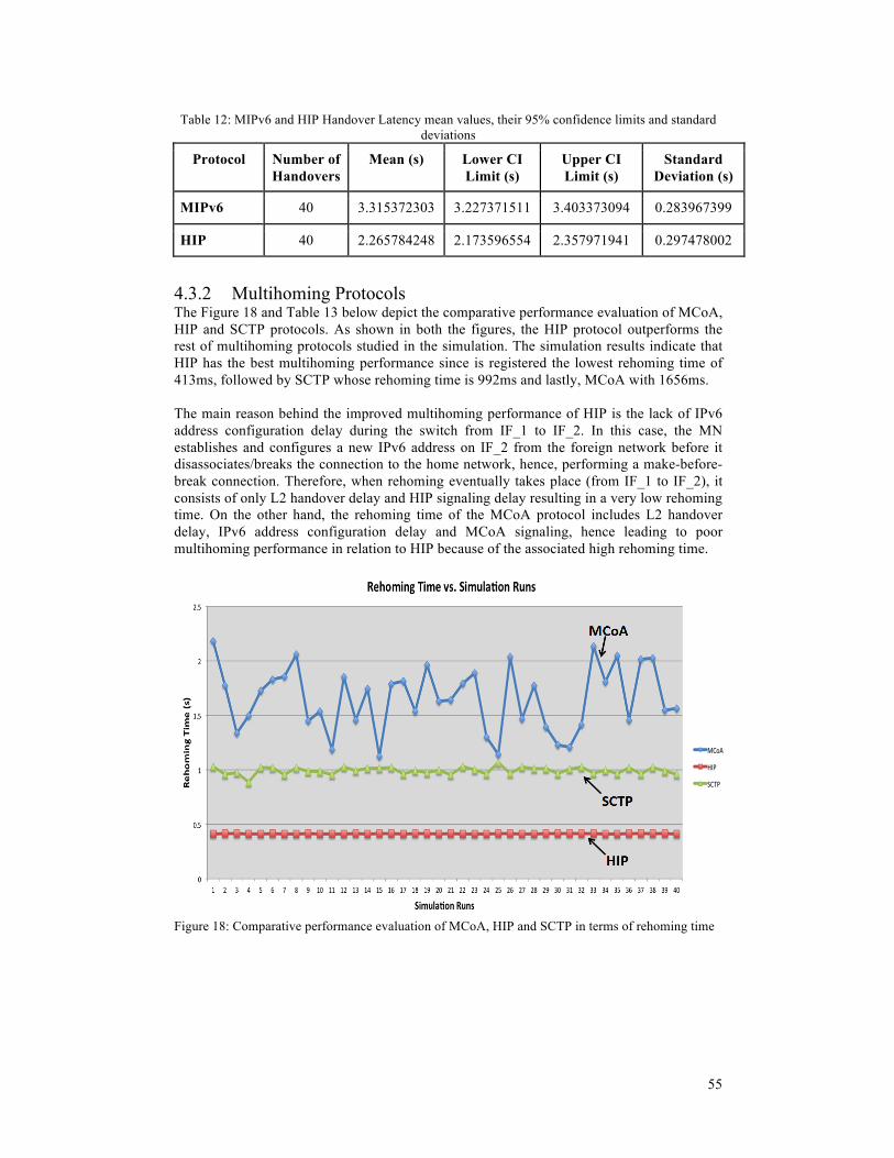
55
Table 12: MIPv6 and HIP Handover Latency mean values, their 95% confidence limits and standard deviations
Protocol Number of Handovers
Mean (s) Lower CI Limit (s)
Upper CI Limit (s)
Standard Deviation (s)
MIPv6 40 3.315372303 3.227371511 3.403373094 0.283967399
HIP 40 2.265784248 2.173596554 2.357971941 0.297478002
4.3.2 Multihoming Protocols The Figure 18 and Table 13 below depict the comparative performance evaluation of MCoA, HIP and SCTP protocols. As shown in both the figures, the HIP protocol outperforms the rest of multihoming protocols studied in the simulation. The simulation results indicate that HIP has the best multihoming performance since is registered the lowest rehoming time of 413ms, followed by SCTP whose rehoming time is 992ms and lastly, MCoA with 1656ms. The main reason behind the improved multihoming performance of HIP is the lack of IPv6 address configuration delay during the switch from IF_1 to IF_2. In this case, the MN establishes and configures a new IPv6 address on IF_2 from the foreign network before it disassociates/breaks the connection to the home network, hence, performing a make-before-break connection. Therefore, when rehoming eventually takes place (from IF_1 to IF_2), it consists of only L2 handover delay and HIP signaling delay resulting in a very low rehoming time. On the other hand, the rehoming time of the MCoA protocol includes L2 handover delay, IPv6 address configuration delay and MCoA signaling, hence leading to poor multihoming performance in relation to HIP because of the associated high rehoming time.
Figure 18: Comparative performance evaluation of MCoA, HIP and SCTP in terms of rehoming time

56
Table 13: Rehoming Time mean values, their 95% Confidence Interval Limits and standard deviations
Protocol Number of Rehoming
Events
Mean (s) Lower CI Limit (s)
Upper CI Limit(s)
Standard Deviation (s)
MCoA 40 1.655510646 1.564614074 1.746407218 0.293311715
HIP 40 0.41270157 0.412324509 0.413078632 0.00121673
SCTP 40 0.992166037 0.982127347 1.002204727 0.032393579
It is imperative to note that SCTP rehoming time depends on the retransmission timeout, whose duration is referred to as RTO. The retransmission timeout ensures data delivery in the absence of any feedback from Host_2 (the peer of Host_1). The RTO is dynamically calculated by Host_1 for each path or addresses connecting to Host_2. When Host_1 starts sending data to Host_2, it expects an acknowledgment for each data packet received by Host_2. This acknowledgement is expected within the calculated RTO on that path. In case host_1 doesn’t receive the acknowledgement within the defined RTO, it assumes a link fault over that path, and hence it retransmits the data packets, i.e., those that have not been acknowledged, on the alternative path as well as the subsequent data packets.
4.4 Validation of Results Our simulation results are very similar to those obtained by other researchers who have tested and simulated the same protocols, HIP [23], MIPv6 [32], MCoA [19] and SCTP [25]. Moreover the individual protocol models on OMNeT++; xMIPv6 [32], HIPSim++ [23], MCoA++ [19] and SCTP on INET Framework [25] have been tested and their correctness evaluated. Subsequently, the results from these protocol models on OMNeT++ are valid and genuine. Additionally, the OMNeT++ simulation tool that we used in this project is popular in the field of network simulation and has been used widely in academia and industry [28] [30]. OMNeT++ has been going through constant development and improvements from versions 2.3 to 4.3 and it has an active OMNeT++ community [30] that discusses technical issues as well as providing latest simulation modules. This evidence shows that our simulation results can be trusted.
4.5 Conclusion This chapter has presented the discussion and analysis of results from the simulations we conducted in the OMNeT++ environment for both multihoming and mobility scenarios. Furthermore, we carried out a quantitative comparison of performance for multihoming and mobility protocols based on their respective metrics used in the simulations. In particular, we intended not just to determine which protocol performs best but also to provide the underlying explanations and interpretation of simulation results. In our simulation setups, we studied two mobility management protocols, MIPv6 and HIP, and three multihoming management protocols, MCoA, HIP and SCTP. Realistic conditions were taken into account for our simulation scenarios in order to obtain accurate results. We investigated the handover performance of mobility protocols in terms of handover latency metric, while rehoming time was the performance metric we used to evaluate multihoming performance for multihoming management protocols. We also discussed the validation of the obtained simulation results. The mobility simulation results indicated that the HIP protocol performs better in handover performance in comparison to MIPv6 since to it has a lower handover latency of 2266ms. The multihoming simulation results also demonstrated that the HIP protocol is the best in

57
multihoming performance among the studied multihoming protocols since it has a very low rehoming time of 413ms. In a nutshell, our quantitative performance comparison reveals that HIP is the best solution that supports both mobility and multihoming in IPv6 network environment. In the next chapter we present the summary of results from the qualitative and quantitative with the aim of identifying the best suitable framework that supports both multihoming and mobility in IPv6 network.

58

59
5 SUMMARY, CONCLUSION AND RECOMMENDATIONS
5.1 Summary of Results This thesis project set out to compare the existing host-based multihoming and mobility protocols and corresponding implementations in the IPv6 heterogeneous environment, and to identify the best suitable framework that supports both multihoming and mobility. To trace the success of the project, four research questions were considered towards the attainment of the project’s aim and objectives: 1) What are the architectural goals and system design principles for the common protocols
and corresponding implementations that support multihoming and/or mobility in IPv6 heterogeneous environment?
We thoroughly reviewed the common protocols and corresponding implementations that support multihoming and mobility in IPv6 as depicted in sections 2.2 and 2.4. 2) What are their cornerstones, advantages, modes of operation, challenges and
drawbacks? We carried out a qualitative comparison of the common protocols and solutions in section 3.2 in terms of the mobility and multihoming criteria, advantages and drawbacks. 3) Which metrics and measurement parameters should be used to simulate and evaluate the
performance of the identified multihoming and mobility solutions? For the quantitative analysis, we used handover latency and rehoming time as the simulations metrics for evaluating the performance of mobility and multihoming protocols respectively. In the simulation study, we focused four protocols i.e. SCTP, MIPv6, MCoA and HIP. In this phase, we designed multihoming and mobility simulation scenarios and successfully executed the simulations on OMNeT++ platform using the respective protocol simulation models. Multihoming and mobility are two different concepts, however, they both have an important feature of providing session survivability. Accordingly, our simulation quantitative analysis was aimed at quantifying session survivability, and thus the Table 14 below shows the summary of performance results.
Table 14: Performance results with 95% confidence interval Protocol Handover Latency (s) Rehoming Time (s) SCTP N/A 0.99! ± 0.0100 MIPv6 3.32! ± 0.0880 N/A MCoA 3.32! ± 0.08801 1.66! ± 0.0909 HIP 2.27! ± 0.0922 0.41! ± 0.0004
4) What is the best solution that supports both multihoming and mobility? In this research project, we have identified HIP as the best suitable framework that supports both multihoming and mobility management in IPv6 heterogeneous network environment. As it can be observed from the quantitative comparison in Table 14, HIP shows the best performance in both the multihoming and mobility scenarios. The main reason for the improved performance of HIP is that it has very low signaling overhead during handovers and rehoming events. Low signaling overhead means that HIP experiences low signaling delay which leads to low handover latency and rehoming time. Moreover HIP implements 1 MCoA is a multihoming extension of MIPv6, where the mobility performance of MCoA is similar to that of MIPv6.

60
soft handovers during rehoming events as it is able to perform L3 signaling before switching to the new interface resulting in very low rehoming time. The low handover latency signifies better handover performance and subsequently improved mobility management. Similarly, the low rehoming time signifies better rehoming performance and consequently improved multihoming management. The analysis from our qualitative comparative framework also illustrates that HIP has better performance based on the mobility and multihoming criteria that we used. Some of the benefits of HIP include integrated mobility and multihoming, enhanced security and requires no changes to the routing infrastructure among others. However, HIP is still under development and its standardization is not yet finalized since the protocol is continuously evolving to suite additional functionalities and extensions. Additionally, the research and results obtained in this thesis project provide a practical demonstration of the principle that the use of multiple addresses enable multihomed nodes to become more fault-tolerant, as failures due to network outages, or due to mobile events and handover cases, alleviates the impact on real-time communication. It is imperative to note that multihoming in the mobile context can provide soft handovers, of which the resulting rehoming time is very low compared to handover latency, leading to even lower packet loss. Additional benefits of multihoming include flow distribution, load sharing and bandwidth optimization.
5.2 Added Value for Practice In this thesis project we have provided a qualitative and quantitative comparison of the existing host-based multihoming and mobility protocols and/or solutions in IPv6 environment. The comparative analysis and results can be used by other researchers to gain more knowledge and deep understanding of this area. Previous efforts have focused on independently studying multihoming and mobility, as they are generally perceived as two separate concepts, and thus handled by different protocols. However, our research framework aimed at identifying the best solution that supports both mobility and multihoming in IPv6 network. Combining mobility and multihoming is a relatively new area of research and it is associated with a number of benefits such as reliability, ubiquity, load sharing, seamless handover, security, bandwidth optimization and flow distribution. Our research has therefore shown the improved performance of multihomed mobility compared to just single homed mobility; hence, our contribution to this research area has been particularly meaningful.
5.3 Limitations and Challenges Faced We faced a few limitations and challenges while working on this project, some of the main problems are elaborated below: a) One of the outstanding limitations we encountered was related to the availability of
simulation protocol models on OMNeT++ software platform. For instance simulation models for SHIM6, mSCTP and MIPSHIM6 are not yet available on OMNeT++. Accordingly we substituted mSCTP with SCTP module of INET Framework, thereby simulating only the multihoming feature of SCTP for fixed hosts. Regarding the SHIM6 protocol and MIPSHIM6 solution, we didn’t have any alternative models to simulate them on OMNeT++, so we didn’t include them in our quantitative comparative analysis.
b) There was also a limitation in the type of applications that could be simulated by
protocol models on OMNeT++. Originally we had intended to use the same type of application i.e. ICMP Pings in all the simulation scenarios, however, HIPSim++ and

61
SCTP models didn’t support ICMP Pings. Instead we used UDP Pings for HIP in HIPSim++ and SCTP Application for SCTP model in INET Framework.
c) In the simulation phase as a whole, we faced a problem of the lack of relevant
documentation and guide materials regarding the operation of simulation protocol models. This meant that we had to spend a lot of time in understanding the underlying source codes and configuring the models in conformance with our developed simulation scenarios.
5.4 Future for Research The process of researching on multihoming and mobility protocols in IPv6 environment has been a great learning experience for us in theoretical framework and simulation implementations. The breadth and depth of the toolsets and software skills involved has tested and developed our capabilities immensely. Since our simulation scenarios considered only a fixed set of configurations such as MN speed of 1m/s, AR interval of 0.03s to 0.07s and Ethernetline delay of 100!", there is need to also investigate the performance of the studied protocols when varying these parameter values. Furthermore, we would like to fully update the used simulation protocol models to the most recent version of OMNeT++ v4.3. This is because most of the models operate with older versions of OMNeT++, moreover some functionalities as required by the RFCs are missing such as Diffie-Hellman security mechanisms in HIPSim++, failure of the home agent in mCoA++ and securing the RO procedure in xMIPv6. Another activity of our future work will focus on developing the missing simulation models on OMNeT++ that are relevant for multihoming and mobility such as SHIM6 and mSCTP. This will provide more protocols for comparison by which we shall use analysis of variance (ANOVA) to ensure that results are statistically significant. Finally the core direction of future work should aim towards improving the performance of the existing multihoming and mobility protocols and/or solutions especially the reduction of signaling delay and security enhancements.

62

63
APPENDIX A
An example of XML Routing Table file <?xml version="1.0" encoding="iso-8859-1"?> <netconf>
<local node="host_1"> <interface name="ppp0" AdvSendAdvertisements="on"> <inetAddr tentative="">2001:aaaa:1:0:0:0:0:1</inetAddr> </interface> <interface name="ppp1" AdvSendAdvertisements="on"> <inetAddr tentative="">2001:bbbb:1:0:0:0:0:1</inetAddr> </interface> <route> <routeEntry routeIface="ppp0" routePrefix="2001:ffff:1:0:0:0:0:0" routePrefixLength = "32" routeNextHop="2001:aaaa:1:0:0:0:0:2"/> </route> <route> <routeEntry routeIface="ppp1" routePrefix="2001:eeee:1:0:0:0:0:0" routePrefixLength = "32" routeNextHop="2001:bbbb:1:0:0:0:0:2"/> </route>
</local> </netconf>

64

65
BIBLIOGRAPHY
[1] A. Achour, K. Haddadou, B. Kervella, and G. Pujolle, “A SIP-SHIM6-based solution providing interdomain service continuity in IMS-based networks,” IEEE Communications Magazine, vol. 50, no. 7, pp. 109–119, Jul. 2012.
[2] L. A. Magagula, H. A. Chan, and O. E. Falowo, “Handover approaches for
seamless mobility management in next generation wireless networks,” Wireless Communications and Mobile Computing, vol. 12, no. 16, pp. 1414–1428, 2012.
[3] M. Zekri, B. Jouaber, and D. Zeghlache, “A review on mobility management and
vertical handover solutions over heterogeneous wireless networks,” Computer Communications, vol. 35, no. 17, pp. 2055–2068, 2012.
[4] B. Sousa, K. Pentikousis, and M. Curado, “Multihoming Management for Future
Networks,” Mobile Networks and Applications, vol. 16, no. 4, pp. 505–17, Aug. 2011.
[5] A. Dhraief and A. Belghith, “Suitability analysis of mobility and multihoming
unification,” in International Conference on Communication in Wireless Environments and Ubiquitous Systems: New Challenges (ICWUS 2010), 8-10 Oct. 2010, pp. 1–6.
[6] A. Dhraief, I. Mabrouki, and A. Belghith, “A service-oriented framework for
mobility and multihoming support,” in Electrotechnical Conference (MELECON), 2012 16th IEEE Mediterranean, 2012, pp. 489–493.
[7] G. Fekete, “Policy based flow management with the host identity protocol for
multihomed hosts,” in First International Conference on Emerging Network Intelligence (EMERGING 2009), 11-16 Oct. 2009, pp. 91–96.
[8] P. Jokela, T. Rinta-aho, T. Jokikyyny, J. Wall, M. Kuparinen, H. Mahkonen, J.
Melen, T. Kauppinen, and J. Korhonen, “Handover performance with HIP and MIPv6,” in 1st International Symposium on Wireless Communication Systems, 2004, pp. 324 – 328.
[9] A. Garcia-Martinez, M. Bagnulo, and I. Van Beijnum, “The Shim6 Architecture
for IPv6 Multihoming,” IEEE Communications Magazine, vol. 48, no. 9, pp. 152–157, Sep. 2010.
[10] R. Stewart and Q. Xie, “Stream Control Transmission Protocol,” RFC 4960,
September, 2007. [11] P. Nikander, A. Gurtov, and T. R. Henderson, “Host Identity Protocol (HIP):
Connectivity, Mobility, Multi-homing, Security, and Privacy over IPv4 and IPv6 Networks,” IEEE Communications Surveys & Tutorials, vol. 12, no. 2, pp. 186–204, Second Quarter 2010.

66
[12] R. Moskowitz, P. Nikander, P. Jokela, and T. Henderson, “Host identity protocol,” RFC 5201, April, 2008.
[13] M. Ratola, “Which layer for mobility? - Comparing Mobile IPv6, HIP and
SCTP,” in HUT T-110.551 Seminar on Internetworking, 2004. [14] R. Wakikawa, V. Devarapalli, G. Tsirtsis, T. Ernst, and K. Nagami, “Multiple
Care-of Addresses Registration,” IETF RFC 5648, October, 2009. [15] A. Dhraief and N. Montavont, “Toward Mobility and Multihoming Unification-
The SHIM6 Protocol: A Case Study,” in IEEE Wireless Communications and Networking Conference, 2008, pp. 2840 –2845.
[16] M. Muslam, H. A. Chan, and N. Ventura, “Host Identity Protocol extension
supporting localized mobility management,” in IEEE Consumer Communications and Networking Conference (CCNC 2011), 8-11 Jan. 2011, pp. 106–110.
[17] C. Perkins, D. Johnson, and J. Arkko, “Mobility Support in IPv6,” RFC 6275,
July, 2011. [18] M. Bagnulo, A. Garcia-Martinez, and A. Azcorra, “IPv6 multihoming support
in the mobile Internet,” IEEE Wireless Communications, vol. 14, no. 5, pp. 92–98, Oct. 2007.
[19] B. Sousa, M. Silva, K. Pentikousis, and M. Curado, “A multiple care of
addresses model,” in Computers and Communications (ISCC), IEEE Symposium, 2011, pp. 485–490.
[20] B. Sousa, K. Pentikousis, and M. Curado, “A study of multimedia application
performance over Multiple Care-of Addresses in Mobile IPv6,” in Computers and Communications (ISCC), IEEE Symposium, 2011, pp. 7–12.
[21] E. Nordmark and M. Bagnulo, “Shim6: Level 3 multihoming shim protocol for
IPv6,” RFC 5533, June, 2009. [22] A. de la Oliva, M. Bagnulo, A. Garcia-Martmez, and I. Soto, “Performance
analysis of the REAchability protocol for IPv6 multihoming,” in Next Generation Teletraffic and Wired/Wireless Advanced Networking. 7th International Conference, NEW2AN 2007, 10-14 Sept. 2007, pp. 443–454.
[23] L. Bokor, S. Novaczki, L. T. Zeke, and G. Jeney, “Design and evaluation of
host identity protocol (HIP) simulation framework for INET/OMNeT++,” in 12th ACM International Conference on Modeling, Analysis, and Simulation of Wireless and Mobile Systems, MSWiM’09, 26-29 Oct. 29, 2009, pp. 124–133.
[24] P. Nikander, T. Henderson, C. Vogt, and J. Arkko, “End-host mobility and
multihoming with the host identity protocol,” RFC 5206, April, 2008. [25] I. Rüngeler, M. Tüxen, and E. P. Rathgeb, “Integration of SCTP in the
OMNeT++ simulation environment,” in Proceedings of the 1st international

67
conference on Simulation tools and techniques for communications, networks and systems & workshops, 2008, p. 78.
[26] S. Koh, Q. Xie, and S. Park, “Mobile SCTP (mSCTP) for IP Handover
Support,” IETF Draft Draft-Sjkoh-Msctp-01, October, 2005. [27] W. D. Kelton and A. M. Law, Simulation modeling and analysis. McGraw Hill
Boston, MA, 2000. [28] A. Varga and R. Hornig, “An overview of the OMNeT++ simulation
environment,” in Proceedings of the 1st international conference on Simulation tools and techniques for communications, networks and systems & workshops, 2008, p. 60.
[29] M. Köksal, “A Survey of Network Simulators Supporting Wireless Networks,”
Middle East Technical University Ankara, Turkey, October 22, 2008. [30] ---, “OMNeT++ Community Site.” [Online]. Available: http://www.omnetpp.o-
rg. [Accessed: 03-Oct-2013] [31] ---, “OMNeT++ User Manual.” [Online]. Available: http://hughesbennett.co.u-
k/public/omnetpp/manual/usman.html#sec101. [Accessed: 03-Oct-2013]. [32] F. Z. Yousaf, C. Bauer, and C. Wietfeld, “An accurate and extensible mobile
IPv6 (xMIPV6) simulation model for OMNeT++,” in Proceedings of the 1st international conference on Simulation tools and techniques for communications, networks and systems & workshops, 2008, p. 88.
[33] L. Bokor, “HIPSim++: A Host Identity Protocol (HIP) Simulation Framework
for INET/OMNeT++.” [Online]. Available: http://www.ict-optimix.eu/index.-php/HIPSim. [Accessed: 03-Oct-2013].
[34] B. Sousa, “mCoA++: Multiple Care-of Address Registration in OMNeT++.”
[Online]. Available: http://mcoa.dei.uc.pt. [Accessed: 03-Oct-2013]. [35] I. Al-Surmi, M. Othman, and B. Mohd Ali, “Mobility management for IP-based
next generation mobile networks: Review, challenge and perspective,” Journal of Network and Computer Applications, vol. 35, no. 1, pp. 295–315, 2012.