performance characteristics of omnidirectional antennas ... · performance characteristics of...
TRANSCRIPT

.
Performance Characteristics of Omnidirectional Antennas for Spacecraft Using NASA Networks (NASA-TR-100680) P E R F O R H A N C E N 07- 295 a4
CHARACTERISTICS OF O M N I D I R E C T I O N B L Abli'Eh NAS FOR SPACECBAFT U S I N G NASA NETWORKS [ N A S A ) 3 1 p A v a i l : N T I S HC A03/BF A01 CSCL 2033 On cl as
G 3 / 1 7 0103498
Larry Hilliard
July 1987
' W NASA Technical Memorandum 100680
z
https://ntrs.nasa.gov/search.jsp?R=19870020151 2020-03-30T13:26:39+00:00Z
NASA Technical Memorandum 100680
Performance Characteristics of Omnidirectional Antennas for Spacecraft Using NASA Networks
Larry Hilliard Micro wave Instrument and RF Technology Branch
Natlonal Aeronaullcs and Space Administration
Goddard Space Flight Center Greenbelt Maryland 2077-1 AC 301 982.4955
1987

All measurement values are expressed in the International System of Units (SI) in accordance with NASA Policy Directive 2220.4, paragraph 4.
ii

PREFACE I .
This document describes the performance capabilities and critical elements of the shaped omni antenna developed for NASA for space users of NASA networks. The shaped omni is designed to be operated in tandem for virtually omnidirectional coverage and uniform gain free of spacecraft interference. These anten- nas are ideal for low gain data requirements and emergency backup, deployment, and retrieval of higher gain RF systems. Other omnidirectional antennas that have flown in space are described in the final section of this document. A performance summary for the shaped omni is in the Appendix.
' *
iii

CONTENTS
Page
1 b -
HISTORICAL BACKGROUND OF SPACE DATA SYSTEMS ............................. TDRSS NETWORK. ................................................................... 1
DESIGN CONSIDERATIONS-OMNIDIRECTIONAL ANTENNAS. 1 .......................
2 DEVELOPMENT PROGRAM-SHAPED OMNI .........................................
3 QUADRIFILAR HELIX. ............................................................... .......................................................... 4 BAFFLED GROUND PLANE
................................................................... 9 TESTING RESULTS
SYSTEM CONFIGURATIONS .......................................................... 10
OTHER OMNIDIRECTIONAL ANTENNAS ............................................. 10
APPENDIX: SHAPED OMNI ANTENNAS.. ........................................... A-1 DATA LINK CALCULATIONS ............................................ A-6
V

PERFORMANCE CHARACTERISTICS OF OMNIDIRECTIONAL
’ . ANTENNAS FOR SPACECRAFT USING NASA NETWORKS
HISTORICAL BACKGROUND OF SPACE DATA SYSTEMS
The success of all space missions has been based on the ability to gather data in space and return that data to earth-based investigators. The National Aeronautics and Space Administration (NASA) tracking and data acquisition stations, located on various parts of the Earth, underwent three distinct evolutions, which were the following:
a. Space Tracking and Data Acquisition Network (STADAN)-STADAN, completed in 1958, was used for tracking unmanned spacecraft in Earth orbits from ground facilities that used sensitive receivers and powerful transmitters.
b. Manned Space Flight Network (MSFN)-During the Mercury, Gemini, and Apollo programs of the early 1960s, MSFN provided astronauts with two-way contact between the ground, the sea, and space.
c. Deep Space Network (DSN)-Implemented in the early 1960s to support NASA’s lunar and planetary missions, DSN used parabolic dish antennas in three stations each separated by approximately 120 O
of longitude. DSN is still operational and continues to support planetary missions under the Jet Pro- pulsion Laboratory (JPL) management.
The Spaceflight Tracking and Data Network (STDN), operational from May 1971 to the era of the Tracking and Data Relay Satellite (TDRS) System (TDRSS) Network, is a combination of the STADAN and the MSFN.
TDRSS NETWORK
It was recognized that the Ground Spaceflight Tracking and Data Network’s (GSTDN) limitations could be removed through a new network that used geostationary satellites rather than ground stations for tracking and communicating with user spacecraft. This network could provide coverage for almost the entire orbital period of a user spacecraft, support a number of spacecraft simultaneously, and have a high assurance of availability. Several NASA studies showed that this network was feasible by using state-of-the-art technology developed in the middle to late 1970s and by using the ATS-6 and the Nimbus-6 spacecraft as demonstration models. This research led to the development of the TDRSS network, which demands higher performance on the TDRSS user spacecraft.
Antennas with higher gain, receivers with more sensitivity, transmitters with higher power, and high perform- ance diplexers have all been developed to meet the requirements for increased effective isotropic radiated power (EIRP) in user spacecraft on their primary data links. TDRSS users also require a group of antennas that provide omnidirectional coverage for deployment, retrieval, and emergency backup communications. A cadre of antennas has been developed to perform this function for TDRSS users.
DESIGN CONSIDERATIONS-OMNIDIRECTIONAL ANTENNAS
Omnidirectional antennas require a simple electronic and mechanical interface and clear field of view (FOV) to qualify as an emergency backup component. They are used to acquire the data link when spacecraft orien- tation may be unknown or uncontrollable. Because they are required to emit nearly isotropic radiation and
1

have a simple configuration, the omnidirectional antenna is best realized by using a single feed. The FOV of a single element antenna will be limited unless the antenna can be positioned well away from the spacecraft. (See Figure 1.)
I DEVELOPMENT PROGRAM-SHAPED OMNI
FOV = 300° ANTENNAS PAST THIS LINE h 3 ARE TOO FAR AWAY FROM THE SPACECRAFT TO WORK I ', PROPERLY FOV -- 270'
\
ANTENNA POSITIONS 1A AND 180' + 180° + INTERFEROMETRY FOV = 350'
1B
I \
I \
FOV = 350'
Figure 1. Fields of View (FOVs) for Various Omnidirectional Antenna Positions
Position 3 is eliminated from consideration because of the adverse effects it would have on the attitude con- trol system, deployment operations, and the additional transmission line losses that it would introduce. Therefore, the backup omnidirectional antenna systems developed by NASA employ a single feed positioned a short distance away from the spacecraft (position 2) or two identical antennas with their signals combined, with a hybrid combiner or switching network, working in tandem and directed 180" apart (positions 1A and 1B).
In the single antenna configuration, there is a zone of spacecraft interference that is unacceptable unless the spacecraft has the ability to keep the TDRS within its FOV. In the tandem configuration, the radiation pat- terns of the two identical antennas interfere with each other along the plane of the spacecraft mounting sur- face because of the phase differences between signals caused by the physical separation of the antennas.
It was recognized that with evolving materials and complex space missions that an improved omni antenna with hemispherical coverage that would satisfy most missions would be desirable.
A development program was initiated with Research and Technology Objectives and Plans (RTOP) funding to pursue the following design improvements on the spacecraft mounted (tandem) version of the omnidirec- tional antenna, known as the shaped omni. The shaped omni program set out to do the following:
2

a. Refine the beamwidth on a single antenna of the set to a level approaching exactly 180" (zt90" off boresight)
b. Maintain uniform gain over the front hemisphere
c. Minimize the radiation in the back hemisphere (toward the spacecraft)
There was a provision included as an option to build an engineering model antenna with the following design considerations and to meet the subsequent performance specifications.
Environmental Objectives
The Shaped Omni Antenna:
Materials - Nonmagnetic space flight materials with negligible outgassing
Temperature - Survives temperature extremes of - 100 " to 100 "C and operates under condi- tions of -65" to 75°C
Vacuum - Operates under a pressure range of 10 - 8 torr to one atmosphere
Noise and Vibration - Survives acoustic and vibration levels required for spacecraft components
Spacecraft Interface Objectives
Size and Weight - Provides user spacecraft compatibility by minimizing the size and weight. (Limits for the original engineering model were set as a 36-in.-diameter sphere, weighing less than 5 lb)
- Uses a single SMA RF connection
- Can be mast-mounted or spacecraft-mounted
Connectors
Mounting
Performance Objectives
Polarization - Uses left-hand circularly polarized signals for transmission and reception
Gain - Provides gain greater than - 1 dB throughout the front hemisphere
QUADRIFILAR HELIX
The radiating element chosen for the shaped omni antenna is the quadrifilar helix (Figure 2). It is comprised of identical radiators wound around a tube of teflon and fiberglass and fed in phase quadrature to create an omnidirectional radiator.

, TEFLON-FIBERGLASS SUBSTRATE
r
I/ II 1 I I I I A
Y
4 HELICAL ELEMENTS goo OUT OF PHASE
T BALUNS 7 .
SMA
CONNECTOR BRANCH LINE HYBRID TUNING NETWORK
Figure 2. Quadrifilar Helix Radiating Element
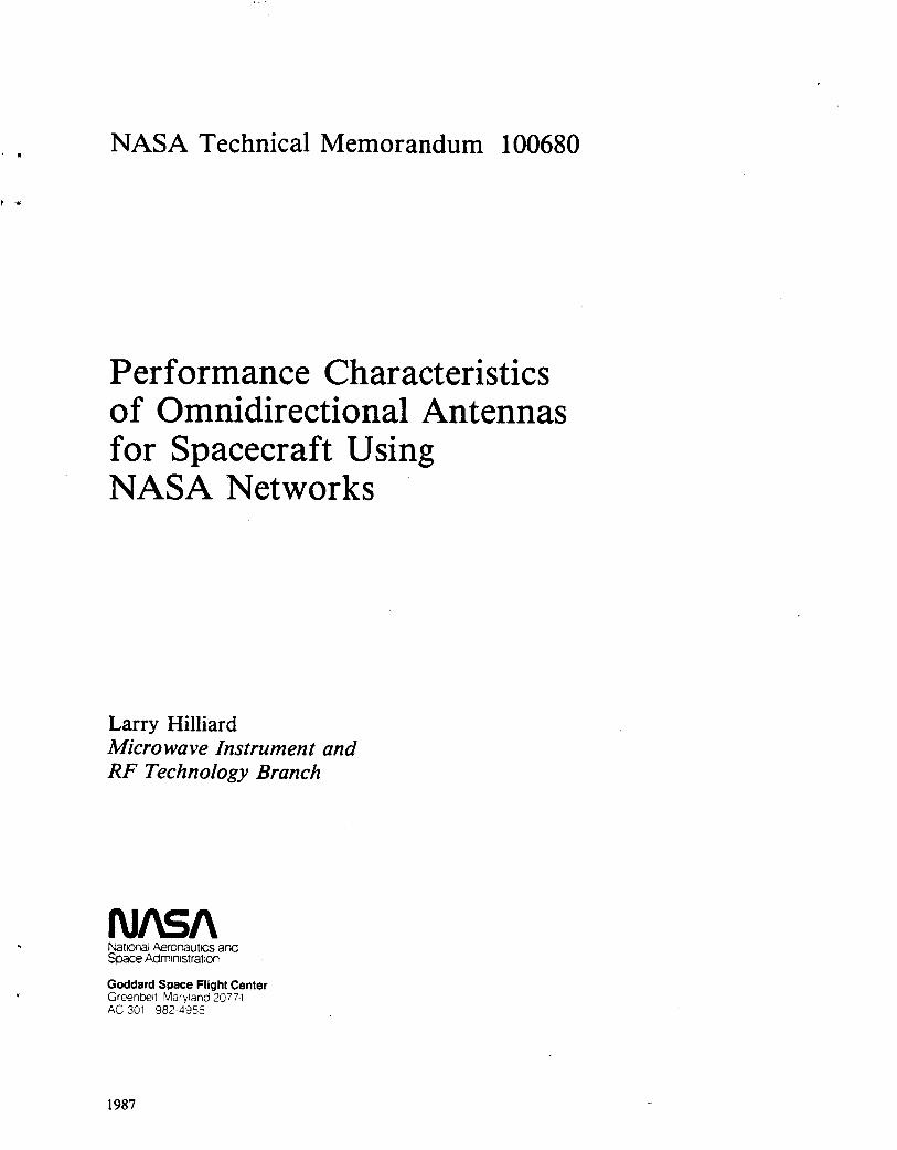
The element assembly will be used to transmit and receive. Therefore, to achieve the required bandwidth, a double-tuned matching network with 90 O hybrid couplers and baluns is a necessary component as part of the feed. The matching network uses tuning stubs and impedance transformer sections on a microstrip board. Theoretically, the element assembly is matched exactly at 2,106 and 2,287 MHz, as shown in Figure 3.
An interface connector feeds the hybrids, which provide two 90 O signals for the tuning network. The tuning network feeds four balanced signals to the ‘elements through baluns. The hybrid and tuning networks are microstrip boards bonded back to back. The baluns are 1 : 1, 180 O coaxial devices connected to the base of the element quad. The elements are wire supported on a cylinder of thin teflodfiberglass substrate. The quadrifilar element alone creates a cardioid pattern like the one shown in Figure 4.
BAFFLED GROUND PLANE
The ground plane of the shaped omni antenna causes the sharp cutoff of the pattern to occur in the hemisphere behind the ground plane. Figure 5 shows the latest model of the shaped omni. It weighs 3 lb and uses a 12-in.- diameter low-profile cone incorporating four concentric circular baffles. In the Appendix, Figure X-2 shows the original 36-in.-diameter shaped omni, that weighed 20 lb and had more than 30 baffles. Using flight materials we project that weight can be reduced to less than 2 lb.
The cone angle is 78 O, a 12 O slope above the plane normal to the radiating element. The height of the baffles, their separation, the slope of the ground plane, and fringing all affect the angle of cutoff. They were chosen to effect coverage down to 5 O above the horizontal for an 8 to 10 percent bandwidth (2,100 to 2,300 MHz). At a single frequency, very sharp cutoff can occur, but the spacing of the baffles was continuously varied to achieve slightly slower cutoff over a wide bandwidth. The chokes are arranged so that the higher frequen- cies are attenuated by baffles closer to the element and the lower frequencies are attenuated by baffles closer to the perimeter. The engineering model performed better at the higher of the two frequencies (Figure 6).
The baffles act as chokes in place of the normal conductive surface and suppress the vertical component of the signal. GSFC’s tests of the shaped omni used conductive materials to short circuit many of the perimeter baffles. The results of these tests suggested that the center baffles had a greater effect on the attenuation of unwanted radiation.
-
4
270 O 90 O
180°
Figure 3. Quadrifilar Helix Input Impedance With the Double Tuning Network
5

Figure 4. Cardioid Pattern Created by Quadrifilar Alone (2,287 MHz Without Ground Plane)
6

Figure 5. Shaped Omni Antenna
7

h
W Q
M c
8
Because the large ground plane on the first engineering model pushed the limits of spacecraft mounting con- straints, a second shaped omni was fabricated that uses a 12-in. ground plane. An analysis of the tradeoff between a larger ground plane and enhanced antenna performance will be included with the final report on the 12-in. engineering model. (See Appendix.)
The 12-in. shaped omni uses only four baffles and provides hemispherical coverage at the correct frequen- cies. The patterns show a predictable degradation in the horizon cutoff characteristics. This effect is a direct result of reducing the size of the ground plane. It was determined that the center baffles on the 36-in. shaped omni were effectively shorting out the element, and the engineering model responded best at a higher fre- quency-2,425 MHz. The advantage of removing these interior baffles on the 124x1. design was twofold: first, there is a better response for the frequency range of interest; and, second, it creates a ground plane of lower complexity for easier manufacture. It was also determined that the wideband frequency response of the baffles was better achieved by putting the widely spaced, low-frequency baffles in the center and the baffles responding to high frequency on the edge of the ground plane. A change in materials was made on the 1241-1. ground plane. The base material was copper, which added weight but allowed the baffles to be soldered into place without plating. This allowed the baffles to be optimally placed and the solution to be easily arrived at by an empirical method. Extra rigidity was added to the quadrifilar element for ease in handling. There is no requirement to keep the material copper. The biggest factor in maintaining a good pattern is the symmetry of the baffles and the helix.
TESTING RESULTS
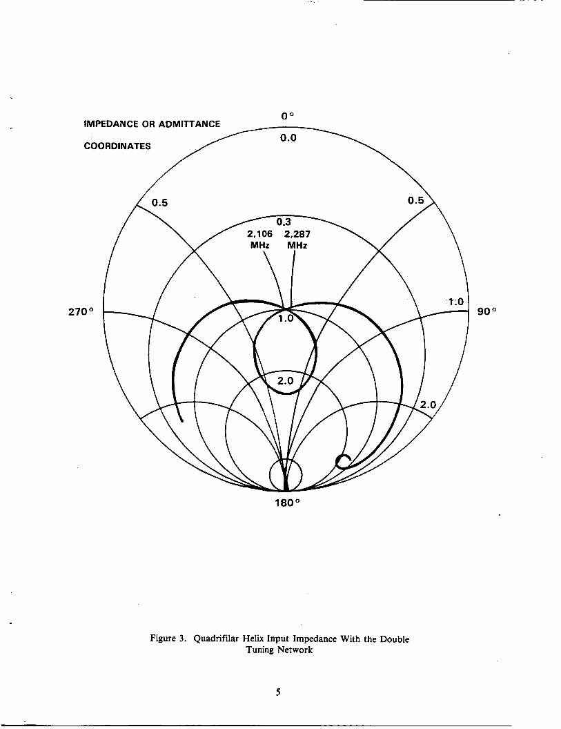
The shaped omni antenna has been tested as a single antenna to investigate its ability to meet the perform- ance objectives of the development program. Besides the low-angle cutoff exhibited in Figure 6, the shaped omni also met the performance criteria shown in Table 1 over the 200-MHz frequency range.
Table 1 Performance Specifications for the Shaped Omni Antenns
Parameter
Frequency (MHz)
Gain (dBi): - 85<0<85 0< - 100,0<100
VSWR (ref 50 Q)
Phase Variation (electrical deg per mechanical deg)
Power Handling (W)
Band 1
2,106 *20
0 - 35
2: 1
<5
10
Band 2
2,287 *20
0 - 35
1 .a: 1
<5
10
9

SYSTEM CONFIGURATIONS
Two omnidirectional antenna set systems configurations are readily assembled with two shaped omni anten- nas. The coupled configuration is shown on the left side of Figure 7. A composite pattern was calculated for a pair of antennas directed 180” apart and fed from points approximately 30 wavelengths apart, to simulate the width of a hypothetical spacecraft. In the areas that the individual antenna’s beams overlap, an in- terferometry pattern is observed due to the difference in signal phase.
Another configuration of shaped omni antennas would have two antennas switched into the transponder. On the right side of Figure 7, the switched configuration adds some complexity and RF losses but further improves the radiation patterns so that the zone of interferometry is reduced to image effects. A more detailed link margin analysis is shown in the “Data Link Calculations” in the Appendix.
Additional patterns were taken of the shaped omni antenna to study the effect of a large reflective mounting surface. Antennas mounted in positions 1A and 1B of Figure 1 will exhibit a pattern like those shown in Figure 8. A 4- by 8-ft piece of aluminum was used to simulate a spacecraft mounting surface. Because the shaped omni ground plane was originally designed for a diameter of 36 in., the engineering model was not flush mounted to the 4- by 8-ft surface, but a gap of approximately 3 in. was left. By eliminating this gap, the user will eliminate the gain fluctuations in the front hemisphere and attain the steep angle cutoff characteristics available with spacecraft mounting. This effect has been studied extensively in microstrip om- ni antennas. (See the “Other Omnidirectional Antennas’’ Section.)
OTHER OMNIDIRECTIONAL ANTENNAS
There are several other antennas that have been developed to serve the purpose of providing omnidirectional coverage for space satellites.
Spacecraft Mounted
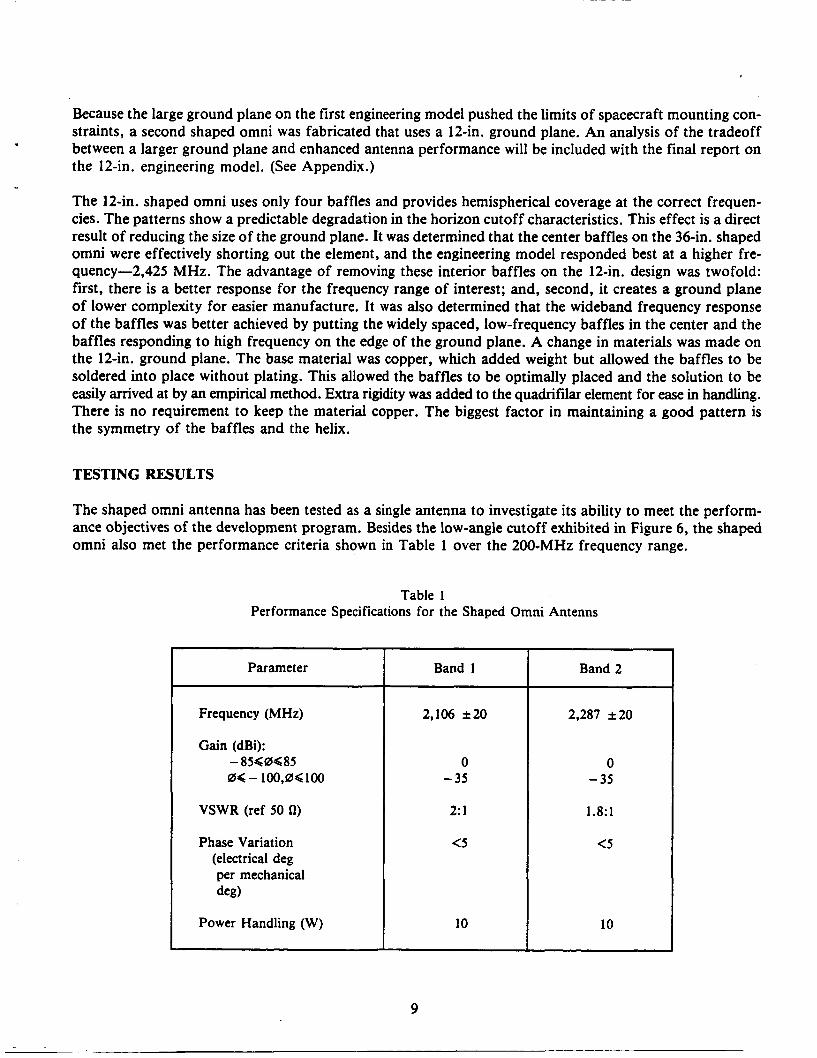
Another way of getting omnidirectional coverage from a low-profile antenna is to use a microstrip belt array antenna. The Canadian Communications Technology Satellite (CTS) antenna and the Air Force P78-1 satellite used microstrip belt antenna arrays around their perimeter (Figure 9).
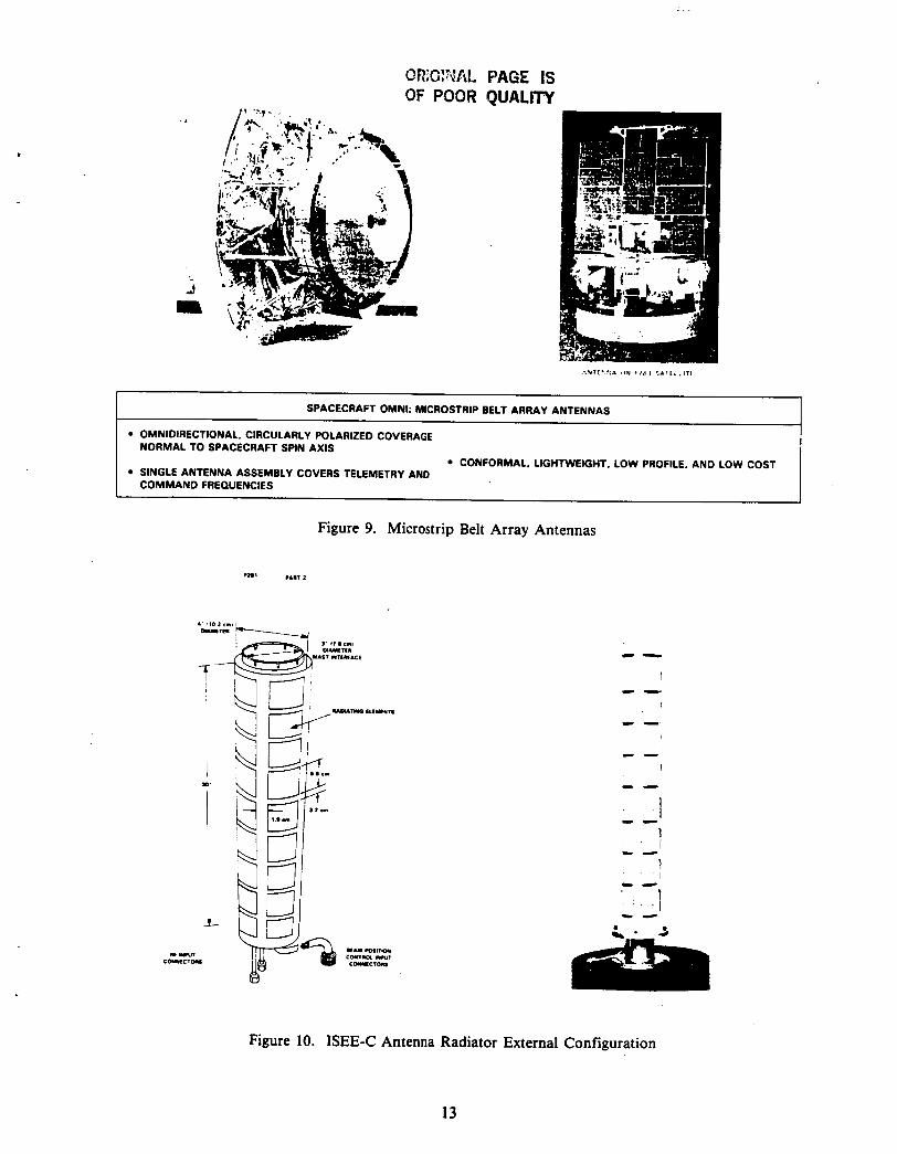
Goddard has used microstrip patches around a deployable boom for the International Sun-Earth Explorer (ISEE) Spacecraft. The ISEE antennas pictured in Figure 10 provide simultaneous right- and left-hand cir- cular polarization with 15 dB minimum isolation between ports. The 32-element antenna provides 10 dBi gain and a minimum 7 dBi gain at & 10” from the equator with six different beam combinations.
Microstrip Radiators
These cylindrical antennas use rectangular microstrip patches. Circular patches may also be used. Aluminum radiators mounted on a teflonlfiberglass printed circuit board use conductive cladding on the lower side as the microstrip ground plane. For the rectangular patches, slots are formed perpendicular to the feed line between the edge of their radiating element and the ground plane parallel to it. The fields of both edges rein- force each other in the front hemisphere if they are located approximately !h wavelength apart. A % wavelength square element can be fed by two lines excited in phase quadrature to provide circular polarization. Another
10

m
u? 'El
0
8 I 0 E r v)
m
u? 0 0 0 3 +I
0
f-
2 a 0 a ? rg
X
m
Y QD
0 0
D
(3 +I
> a
5 Ov) a w w w u a
t;
- B E
$ '
E
z: w 2
11

I
t
d I
8
'..YIL'*.A ,,.1 11.1 I 51111.111
SPACECRAFT OMNI: MICROSTRIP BELT ARRAY ANTENNAS
OMNIDIRECTIONAL. CIRCULARLY POLARIZED COVERAGE NORMAL TO SPACECRAFT SPIN AXIS
CONFORMAL. LIGHTWEIGHT, LOW PROFILE, AN0 LOW COST SINGLE ANTENNA ASSEMBLY COVERS TELEMETRY AND COMMAND FREQUENCIES
Figure 9. Microstrip Belt Array Antennas
Figure 10. ISEE-C Antenna Radiator External Configuration
13

appmach is to use a '/z wavelength diameter disk fed at points 90 O apart. The ERBS omnidirectional antenna r a o r was such a disk-shaped microstrip patch fed at a single point. An appropriately sized notch or tab added at the edge of the disk introduces a nonsymmetry and the disk radiates with circular polarization. (See Figures 1 l a and 1 lb.)
. .
RADIATING ELEMENT
Figure 1 la. Circularly Polarized Microstrip
QUADRATURE FEED POINT
(FOR CIR. POL1 FEED POINT
PLANE RATE TRlC
REMOVED FOR CLARITY)
Figure 1 lb. Disk Shaped Circular Polarized Microstrip Radiator
Perf-ance
Nearfp uniform gain for all angles out to 7 7 O from boresight can be obtained by shaping the beam pattern n o d l y obtained from a microstrip patch. Raising the microstrip element a fraction of a wavelength above the stmctural ground plane depresses the beam on boresight and enhances its energy directed toward broader
14

look angles. Varying the size of the ground plane changes the performance of the antenna markedly. Varying the height above the ground plane also affects the resultant radiation pattern (Figure 12).
The ISEE-3 32 element antenna used four additional radiating elements which were raised off the ground plane for extra beamwidth. A 4-element omni mounted just above the 32-element antenna and suspended further from the substrate provided -4.5 dBi coverage over a k45 O beamwidth.
Other specifications such as VSWR and bandwidth are illustrated over different temperature ranges in Table 2.
Figure 12. Qualitative Effect of Radiative Height on Patterns
15
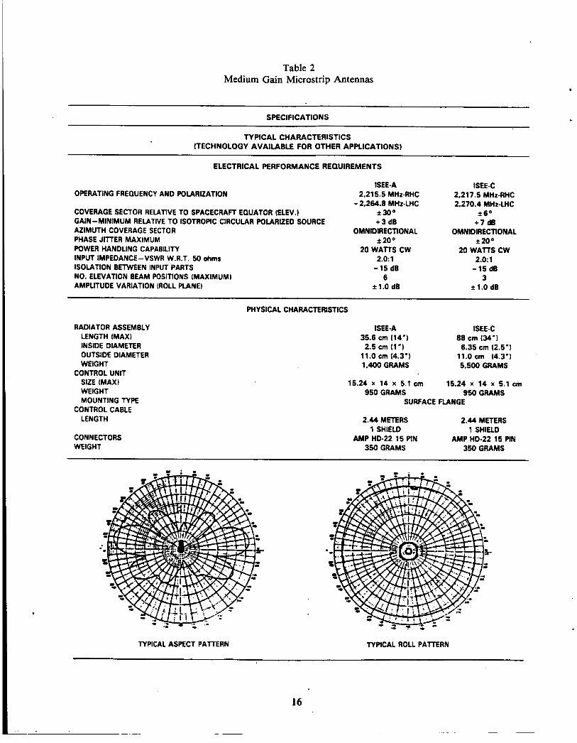
. SPECIFICATIONS
TYPICAL CHARACTERISTICS (TECHNOLOGY AVAILABLE FOR OTHER APPLICATIONS)
ELECTRICAL PERFORMANCE REQUIREMENTS
OPERATING FREQUENCY AND POLARIZATION
COVERAGE SECTOR RELATIVE TO SPACECRAFT EQUATOR (ELEV.)
AZIMUTH COVERAGE SECTOR PHASE JITTER MAXIMUM POWER HANDLING CAPABILITY INPUT IMPEDANCE-VSWR W.R.T. 50 ohms ISOLATION BETWEEN INPUT PARTS NO. ELEVATION BEAM POSITIONS (MAXIMUM) AMPLITUDE VARIATION (ROLL PLANE)
GAIN-MINIMUM RELATIVE TO ISOTROPIC CIRCULAR POLARIZED SOURCE
SEE-A 2,215.5 MHz-RHC
-2.264.8 MHz-LHC *300 + 3 dB
OMNIDIRECTIONAL f 200
20 WATTS CW 2.0:l
-15dB 6
kl.0 dB
ISEE-C 2.217.5 MHz-RHC 2.270.4 MHz-LHC
* 6 O
+7 dB OMNIDIRECTIONAL
*200 20 WATTS CW
2.0:l -15 dB
3 1.0 dB
RADIATOR ASSEMBLY LENGTH (MAX) INSIDE DIAMETER OUTSIDE DIAMETER WEIGHT
CONTROL UNIT SIZE (MAX) WEIGHT MOUNTING TYPE
LENGTH CONTROL CABLE
CONNECTORS WEIGHT
PHYSICAL CHARACTERISTICS
ISEE-A ISEE-C 35.6 cm 114") 2.5 cm (1') 6.35 cm (2.5')
11.0 crn (4.3') 11.0 cm (4.3') 1.400 GRAMS 5.500 GRAMS
88 cm (34-1
15.24 x 14 x 5.1 cm 15.24 x 14 x 5.1 cm 950 GRAMS 950 GRAMS
SURFACE FLANGE
2.44 METERS 2.44 METERS 1 SHIELD 1 SHIELD
350 GRAMS 350 GRAMS AMP HD-22 15 PIN AMP HD-22 15 PIN
TYPICAL ASPECT PAllERN TYPICAL ROLL PATERN
16

APPENDIX
SHAPED OMNI ANTENNAS
FOR SPACE USERS OF NASA NETWORKS -
Source material for this Appendix is from the Ball Aerospace Systems Division, P.O. Box 1062, Boulder, Colorado, 80306. This paper is edited by L. Hilliard of the Goddard Space Flight Center.

APPENDIX: SHAPED OMNI ANTENNAS
SPECIFICATIONS
TYPICAL CHARACTERISTICS (TECHNOLOGY AVAILABLE FOR OTHER APPLICATIONS)
ELECTRICAL PERFORMANCE REQUIREMENTS
RCV XMlT 2,106.4 f 20 MHz-LHC
2,287.5 i 20 MHz-LHC
- OPERATING FREQUENCY AND POLARIZATION
COVERAGE SECTOR RELATIVE TO SPACECRAFT EQUATOR (ELEV.) *80° GAIN - MINIMUM RELATIVE TO ISOTROPIC CIRCULAR POLARIZED SOURCE 0 dBi AZIMUTH COVERAGE SECTOR *80° PHASE JITTER MAXIMUM *5O POWER HANDLING CAPABILITY 10 WATTS INPUT IMPEDANCE-VSWR W.R.T. 50 ohms 2.0: 1 ISOLATION BETWEEN XMlTlRCV FREQUENCIES SINGLE PORT CIRCULATOR REQUIRED AMPLITUDE VARIATION FRONT HEMISPHERE f 1 dB MAX
PHY SlCAL CHARACTERISTICS
.RADIATOR ASSEMBLY HEIGHT OF RADOMElELEMENT ASSEMBLY DIAMETER OF RADOME DIAMETER OF GROUND PLANE WEIGHT
SIZE (MAX) WEIGHT
LENGTH
CONTROL UNIT HOUSING
CONTROL CABLE
CONNECTORS WEIGHT
5" 3"
12" 2 Ib (WICOPPER GROUND PLANE)
BROADBAND NETWORK 2" DIAMETER x 1 %
1 Ib
COAXIAL 1 METER SMA
350 GRAMS
SEMI-RIGID
A- 1

B
x
A-2

Figure X-2. Shaped Omni Antenna (36 in. Shaped Omni below)
A-3

If space permits, the baffled ground plane cone can be extended again for applications that require increased coverage on the horizon. The original 36 in. shaped omni exhibited outstanding cutoff characteristics A 85 O
off axis. Reducing the size of the 12 in. ground plane would eliminate the broadbanding capabilities, and quickly degrade the rapid cutoff characteristics of the antenna assembly. The 12 in. design nearly optimizes the mechanical electronic tradeoff, as Figure X-3 shows.
I
A,-E .Q
CUTOFF/COVERAGE
10 " 12 " 24 " 36 "
SIZE OF BAFFLED GROUND PLANE
Figure X-3. Effects of Ground Plane Size on Pattern Cutoff
A-4

DATA LINK CALCULATIONS
f = 2,106.4 MHz RECEIVE COUPLED CONFIGURATION
SIGNAL LOSS 3.5 dB
DIPLEXER f = 2.0 dB
T, =125O
LINE LOSS
dBs CONVERTED L = LOSSES TO MULTIPLES F = NOISE FIGURE
T, = - 2 T a + 290 (y) +290 (f -1) L
+ 290 (-) + 290 (0.5848) = 373.2 250
3.8019 - - -
No = 228.6 - 25.7 = 202.9 dBW/HZ u
A-5

FORWARD LINK COUPLED
TDRS ElRP PATH LOSS RECEIVE ANTENNA GAIN POLARIZATION LOSS UQPSK LOSS HYBRIDILINEIDIPLEXER LOSSES EQUIPMENT IMPLEMENTATION LOSS RECEIVED SIGNAL LESS TRANSPONDER NO REDUCTION
DATA RATEIREQUIRED SIN,
S-BAND SINGLE ACCESS
(SSA)
43.6 dBW
0.0 dB - 191.5 dB
-3.0 dB -0.5 dB -5.8 dB -3.0 dB
- 160.2 dBW 202.9 dB bpsIW
42.7 dB bps 8 KBPSI - 39.0 dB bps
’ S-BAND MULTIPLE ACCESS
(SMA)
34.0 dBW
0.0 dB -3.0 dB -0.5 dB -5.8 dB -3.0 dB
- 169.8 dBW
- 191.5 dB
202.9 dB bps/W 33.1 dB bps
1 KBPS/ - 30.0 dB bps 3.1 dB I 3.7 dB
LINK MARGINS IN AREA OF UNIFORM GAIN ( k 80 O OFF BORESIGHT)
RETURN LINK
TRANSMIT POWER 5 W COAXIAL LINEIDIPLEXERIHYBRID ANTENNA GAIN POLARIZATION LOSS
EFFECTIVE ElRP TDRSS USERS GUIDE CONSTANT (DG-1) ACHIEVABLE DATA RATE DATA RATEILESS REQUIRED SIN,
7 dBW 5.8 dB
+ 1.0 dB 3.0 dB
-0.8 dBW 34.0 dB 33.2 dB bps
1 KBPSI- 30.0 dB bps 3.2 dB
7 dBW 5.8 dB
+ 1.0 dB 3.0 dB
-0.8 dBW 23.6 dB 22.8 dB bps
125 bpd - 21 .O dB bps 1.8 dB
LINK MARGINS IN AREA OF UNIFORM GAIN ( f 80 O OFF BORESIGHT)
. . .
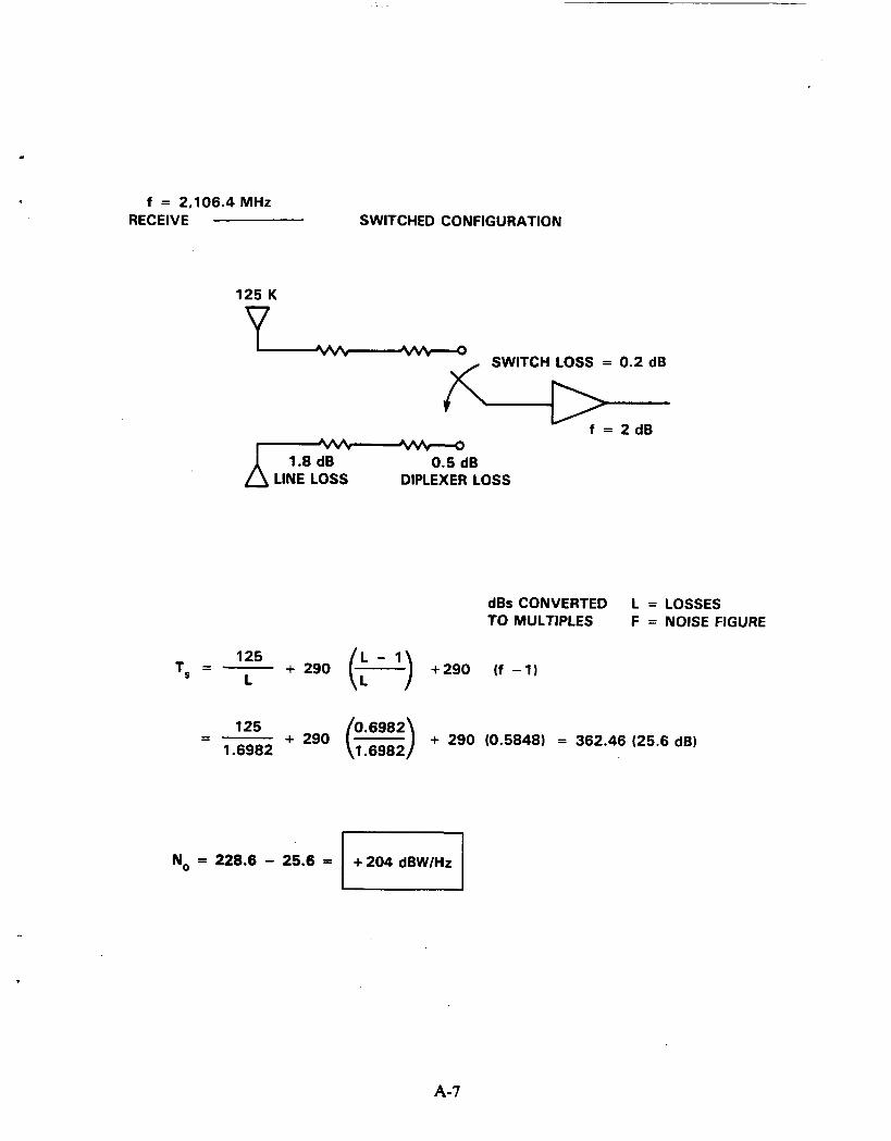
f = 2,106.4 MHz RECEIVE SWITCHED CONFIGURATION
125 K v SWITCH LOSS = 0.2 dB
Y
f = 2 d B
1.8 dB 0.5 dB LINE LOSS DIPLEXER LOSS
dBsCONVERTED L = LOSSES TO MULTIPLES F = NOISE FIGURE
= - 125 + 290 ~ : ~ ~ ~ ~ ) - + 290 (0.5848) = 362.46 (25.6 dB) 1.6982
No = 228.6 - 25.6 = +204 dBW/Hz El
A-7

RETURN LINK SWITCHED
10 KBPSl-40.OdB bps 7.1 dB
TDRS ElRP PATH LOSS RECEIVE ANTENNA GAIN POLARIZATION LOSS UQPSK LOSS SWlTCHlLlNElDlPLEXER LOSSES EQUIPMENT IMPLEMENTATION LOSSES RECEIVED SIGNAL LESS TRANSPONDER NO REDUCTION
1 KBPSI- 30.0 dB bps 7.5 dB
DATA RATElREQUlRED SIN,
34.0 dB b p s m 36.5 dB bps
1 KBPSl - 30.0 dB bps
S-BAND SINGLE ACCESS
(SSA)
23.6 dB bpsMl 26.1 dB bps
125 bpsl - 21 .O dB bps
43.6 dBW - 191.5 dB
0.0 dB -3.0 dB -0.5 dB -2.5 dB
S-BAND MULTIPLE ACCESS
(SMA)
34.0 dBW - 191.5 dB
0.0 dB -3.0 dB -0.5 dB -2.5 dB
-3.0 dB -3.0 dB - 156.9 dBW I -166.5dBW
204.0 dB bpslW 204.0 dB bpsMl 47.1 dB bps I 37.5 dB bDS
LINK MARGINS IN AREA OF UNIFORM GAIN ( f 90 O OFF BORESIGHT)
RETURN LINK
TRANSMIT POWER COAXIAL LlNElDlPLEXERlSWlTCH ANTENNA GAIN POLARIZATION LOSS
EFFECTIVE ElRP
ACHIEVABLE DATA RATE DATA RATElLESS REQUIRED SIN,
TDRSS USERS GUIDE CONSTANT (DG-1)
7 dBW 2.5 dB
3.0 dB +1.0 dB
7 dBW 2.5 dB
+1.0 dB 3.0 dB
2.5 dBW I 2.5 dBW
LINK'MARGINS IN AREA OF UNIFORM GAIN ( f 90 O OFF BORESIGHT)
A-8

.
1. Report No.
TM 100680
Report Documentation Page 2. Government Accession No. 3. Recipient's Catalog No.
4. Title and Subtitle
Performance Characteristics of Ormidirectional Antennas for Spacecraft Using NASA Nelxorks
5. Report Date
6. Performing Organization Code
727.1
7. Author(s) 8. Performing Organization Report No.
Lawrence M. Hill iard
9. Performing Organization Name and Address
Micrmave Instrument and RE' Techmlogy Branch Goddard Space Flight Center G r e e n b e l t , Maryland 20771
12. Sponsoring Agency Name and Address
NAS A / H e a d q u a r ters Washington, D.C. 20546
727-310-20-46 11. Contract or Grant No.
13. Type of Report and Period Covered
Technical bWmrandun 14. Sponsoring Agency Code
16. Abstract
This document describes the performance capabilities ard critical elements of the shaped Omni antenna developed for NASA for space users of NASA networks. The shaped anni is designed to be operated i n tandm for virtually omni- directional coverage and unifonn gain free of spacecraft interference. These antennas are ideal for low gain data requirements and emergency backup, deployment, and retr ieval of higher gain RF systems. antennas that have flown i n space are described i n the f inal section of t h i s document.
This docment introduces organizations anl projects to the shaped anni applications for NASA's spce use. Coverage, gain, weight, p e r , and implementation and other performance information for satisfying a wide range of data requirements are included.
Other amidirectional
A perfonnance smrnary for the shaped anni is i n the Appendix.
19. Security Classif. (of this repon) 20. Security Classif. (of this pagel
17. Key Words (Suggested by AuthorWl I 18. Distribution Statement
21. No. of pages 22. Price
Antel-lllaS Qnnidirectional Coverage spa- carmand /Te 1m~tx-y
Unclassified - Unlimited Subject Category 17
Unclassified 1 Unclassified I I I
IASA FORM 1626 OCT 86