performance characteristics of an annular conical aerospike nozzle with freestream effect
TRANSCRIPT

Performance Characteristics of an Annular Conical AerospikeNozzle with Freestream Effect
S. B. Verma∗
National Aerospace Laboratories, Bangalore 560 017, India
DOI: 10.2514/1.40302
Anexperimental investigation has been carried out to study the performance andbase pressure characteristics of a
Mach 2.0 annular conical aerospike nozzle with and without freestream flow. The effect of cowl length, plug length,
and plug contour variation on the nozzle performance and base pressure characteristics is studied. It is observed that
the overexpansion shock from the internal nozzle, overexpansion shock on the spike surface, and the expansion fan
from the cowl lip of the internal nozzle dominate the overall flowfield development. The presence of freestream flow
reduces the nozzle performance by approximately 4% relative to static conditions. Base pressure characteristics are
observed to be strongly influenced by the movement of these shocks on the plug surface, and their subsequent
interaction with the inner shear layer controls the base-wake closure. Relative to the conical plug configuration, the
contouredplug shows considerably enhancedbase pressure characteristics. Real-timepressuremeasurements on the
spike reveal highly unsteady flow in the intermittent region of separation.
Nomenclature
Acowl exit = annular area at the cowl exit, ms�1
Cf�i� = thrust coefficient of an ideal nozzleCf�x� = estimated thrust coefficient, F=AtPoj
F = estimated thrust in the axial direction, Nf = fluctuation frequency, HzG�f� = power spectral densityht = height of the annular throat, mmL = full length of the spike from the nozzle throat, mml = length of the cowl, mmM1 = freestream Mach numberPa = ambient pressure, psiPb = plug base pressure, psiPc = stagnation chamber pressure, psiPcowl exit = pressure at the cowl exit, ms�1
Pe = nozzle exit pressure, psiPoj = jet stagnation pressure, psiPw = local wall pressure on the spike surface, psiVcowl exit = velocity at the cowl exit, ms�1
X = coordinate along the nozzle axis, mm�i = area ratio of the internal nozzle� = area ratio of the aerospike nozzle
I. Introduction
C ONVENTIONAL bell nozzles, due to their fixed geometry,suffer from reduced engine performance at low altitude due to
overexpansion and at high altitude due to underexpansion; seeFig. 1a. Therefore, to achieve relatively better performance over thedesired flight envelope, multistaging of the launch vehicle has beenpreferred to date. Forfirst-stage application, themaximumgeometricarea ratio available is constrained by flow separation and the relatedside-load activity. For upper-stage applications, the maximumgeometric area ratio is limited by the available integration vol-ume [1]. But with a change in launcher stage design from the
tandem to parallel configuration, the main stage engine is nowexpected to fulfill a wide range of operating conditions during thelauncher’s ascent [2]. Because these main-stage engines spend mostof their flight time at high altitude, a designer prefers a high area-ratio
Fig. 1 Conventional bell nozzle: a) schematic of variousflow conditionsprevalent in a bell nozzle with a change in ambient pressure, and
b) comparison of theoretical nozzles with conventional bell nozzles and
aerospike nozzles [11].
Presented as Paper 5290 at the 44th AIAA/ASME/SAE Joint PropulsionConference and Exhibit, Hartford, CT, 20–23 July 2008; received 7 August2008; revision received 26 November 2008; accepted for publication 26November 2008. Copyright © 2008 by the American Institute of Aeronauticsand Astronautics, Inc. All rights reserved. Copies of this paper may be madefor personal or internal use, on condition that the copier pay the $10.00per-copy fee to the Copyright Clearance Center, Inc., 222 RosewoodDrive, Danvers, MA 01923; include the code 0748-4658/09 $10.00 incorrespondence with the CCC.
∗Research Scientist, Experimental Aerodynamics Division, Council ofScientific & Industrial Research; [email protected].
JOURNAL OF PROPULSION AND POWER
Vol. 25, No. 3, May–June 2009
783
Dow
nloa
ded
by U
NIV
OF
CA
LIF
OR
NIA
LO
S A
NG
EL
ES
on M
ay 2
, 201
4 | h
ttp://
arc.
aiaa
.org
| D
OI:
10.
2514
/1.4
0302

nozzle with high vacuum performance as the key requirement.But moderately large area-ratio nozzles operating at sea levelproduce separated exhaust flow, resulting in performance lossesand high nozzle structural loads [3–6]. Therefore, an ideal nozzlewould be one that continuously adjusts its contour, area ratio, andlength to maximize thrust at each altitude, a concept known asaltitude compensation. But variable area-ratio bell nozzles aremechanically complex and not cost effective for most applica-tions [3].
Different types of nozzle concepts have been discussed and testedon the ground in the past [1,2,7–25]. These include the extendiblenozzle [1] (widely used for upper-stage application) and the dual-bellnozzle [2] (still in the conceptual stage but a strong contender forthe future Ariane vehicle) with single-step altitude adaptationcapabilities, the annular/cluster plug nozzle [8,17–19] with con-tinuous altitude adaptation for first- or upper-stage application, andthe expansion-deflection thrust chamber [12] concept for the upperstage offering substantial decrease in integration volumewithout anymoving parts. Other than the extendible nozzle, however, none ofthese concepts have reached hardware flight status. Recently, anannular aerospike nozzle has been tested for the first time in flight[26]. The linear concept of the annular/cluster plug nozzle is alsoforeseen as a strong contender for the propulsion system of reusablespacecraft [18,19].
The concept of aerospike nozzles was first reported in the 1960s[8–12] and 1970s [13–16], but has recently found renewedinterest the world over as there is a need to increase the payloadcapacity of modern-day launch vehicles. The aerospike nozzle is,basically, a bell nozzle turned inside out that tends to maximizeperformance with altitude change. The outer wall of an aerospike(which serves as the inner wall of the bell) is always exposed toan ambient pressure, and so the external expansion allowscontinuous adaptation to ambient pressure during the entireflight trajectory. This eliminates overexpansion losses at altitudesbelow the nozzle design point. To get the highest benefit withthis nozzle concept, the design pressure ratio and, thus, thegeometrical area ratio should be chosen as high as possible, whichcould be realized with large launcher tail areas and/or high thrustchamber pressures. Figure 1b, reproduced from [11], shows acomparison of various nozzles. The ideal nozzle, indicated by thethick solid line, represents the maximum performance possible. It
gear drive nozzle outer case
schlieren windows supersonic dif fuser
nozzle inner body
nozzle outer body
test model M
rack-pinion arrangement for nozzle axial movement
38.5
32
l =4.5
33.85
R310
152.8
removable section forcowl-length variation
modified section to house the plug nozzle
annular nozzle
Ø32Ø50ht = 9
AeØ75
59.7112.525
afterbody
cowl
35 pressure ports
Ø1.6
Ø0.5
5100% spike
40% spike
a)
b)
Fig. 2 Schematic showing a) the base flow facility at the National Aerospace Laboratories, and b) the plug mounting arrangements and cowl-length
variation. All dimensions are in mm.
NPR
Pw
/Poj
0 0.2 0.4 0.6 0.8 10
0.2
0.4
0.6
0.8
12.102.573.123.824.294.745.225.75
NPR
(Pw-
Pa
)/P
oj
0 0.2 0.4 0.6 0.8 1-0.3
-0.2
-0.1
0
0.1
0.2
0.3
0.4
0.52.102.573.123.824.294.745.225.75
a)
b)Fig. 3 Wall pressure measurements on the conical 100% length spike
without the freestream flow; l=ht � 1:0.
784 VERMA
Dow
nloa
ded
by U
NIV
OF
CA
LIF
OR
NIA
LO
S A
NG
EL
ES
on M
ay 2
, 201
4 | h
ttp://
arc.
aiaa
.org
| D
OI:
10.
2514
/1.4
0302

can be clearly discerned that the aerospike shows the bestperformance at all altitudes. It has been further reported [17] thatmost of the thrust on the spike is generated over the first quarter, sothat the remaining three-quarters can be truncated without much lossin total thrust. However, the thrust lost by removing some portion ofthe spike is compensated by the pressure acting on the base area of thetruncated plug. Such a truncated plug nozzle configuration has theadded advantages of a reduction in engine size andweight, which canthen be used to increase the payload capacity of the launch vehicle,resulting in an overall gain in system performance. Altitude com-pensating effects still occur for such a truncated plug configurationalthough the flow structure downstream of the plug is significantlymodified; hence, studies on plug nozzle configuration with andwithout freestream flow are of particular interest.
This paper reports the results of an experimental investigationperformed on a 15 deg annular conical aerospike nozzle (designMach number 2.0) with and without freestream flow. Earlier studiesreport that at low nozzle pressure ratio, or NPR (P0j=Pa), the basepressure is nearly equal to ambient pressure and becomes constant athigh NPR. The base pressure undergoes significant changes beforeand after this transition occurs, which need to be clearly understoodfor the prediction of base thrust characteristics. Themain objective ofthe test campaign was, therefore, to correlate the variations in basepressure characteristics to changes in the plug flowfield through theeffect of nozzle pressure ratio, percentage truncation, and cowl-length variation and study its implications on nozzle performance. Acomparison of the nozzle performance for all test cases, with andwithout freestream, is made by evaluating the thrust generated on thespike/plug.
II. Experimental Setup and Procedure
A. Wind Tunnel and Test Conditions
Experiments were carried out in the 0.5 m base flow facility, aspecial purpose blowdown-type tunnel (Fig. 2a). Some of the specialfeatures of this tunnel are 1) an axisymmetric variable geometrynozzle, which can provide test Mach numbers in the range of0:4� 0:01–3:5� 0:01 (and unit Reynolds numbers in the range of10–50� 0:2 � 106 m�1); 2) support of the models directly on thenozzle innerbody, thereby completely eliminating the supportsystem interference; 3) fairly well-developed zero pressure gradientturbulent-boundary-layer characteristics on the afterbody; and4) easier mounting and changing of the afterbody-nozzle models.The tunnel has been extensively calibrated, and the results indicategood mean flow uniformity and axisymmetry of the freestream andjet flow in the tunnel.
B. Model and Experimental Setup
The Mj � 2:0� 0:1 conical (15� 0:03 deg half-angle) annularaerospike model was mounted on the central cylindrical inner bodyin such a way that different truncated sections of the spike/plug canbe tested on the same cylindrical central body; see Fig. 2b. Up to 12pressure points (with a pitch of 4� 0:1 mm) were fabricated along asingle line on the full-length spike so as to investigate the flow indetail and to help evaluate the pressure thrust generated on the full-length spike. The exit nozzle radius, re, in this nozzle is fixed as25� 0:1 mm. The annular gap at the throat section (ht) is9� 0:1 mm, and the length (L) of the spike is 59:7� 0:1 mm. Theaerospike nozzle area is defined as the ratio of the area at spike end
Region of compression
Internal shockOverexpansion shock
Separated flow
Expansion fan Type-C
Shear layer
Separated flow
Overexpansion shock
Spike surface
Type-A
Reattached flow
shock pattern
Overexpansion shock
Jet boundaryExpansion fans Type-B
(a) T II
Compression shocks Trailing shock
Overexpansion shock Expansion fan
M<1 Inner shear layer
Expansion fan
Truncated base
Jet boundary Type-B
Expansion fan
Truncated base
Jet boundary
M<1
Inner shear layer
M>1
Envelope shock
Trailing shock
Type-C
Shear layer
Truncated base
Jet boundary
Overexpansion shock
Separated flowTrailing shock
M<1
Inner shear layer
Internal shock
Type-A
a) d)
b) e)
–
c) f)
Jet boundary
Afterbody
Fig. 4 Schlieren pictures with no freestream condition for the full-length spike: a)NPR� 2:1, b)NPR� 2:57, and c)NPR� 3:82. Schlieren pictures
with no freestream condition for the 40% truncated spike: d) NPR� 2:57, e) NPR� 4:15, and f) NPR� 7:0.
VERMA 785
Dow
nloa
ded
by U
NIV
OF
CA
LIF
OR
NIA
LO
S A
NG
EL
ES
on M
ay 2
, 201
4 | h
ttp://
arc.
aiaa
.org
| D
OI:
10.
2514
/1.4
0302

(re � 25� 0:1 mm) to the annular throat area. The length of thecowl, l (measured as the distance from throat section to the cowl lip),is varied between 4:5� 0:1 mm and 9:0� 0:1 mm, giving l=ht �0:5� 0:005 and 1:0� 0:02 (resulting in �i � 1:1� 0:01 and�i � 1:19� 0:01, respectively). A 40% truncation of the full-lengthspike was also fabricated to study the effect of truncation on theoverall nozzle performance. The truncated spike, however, had onlyfive pressure ports for thrust evaluation. Two static pressure portswere included in the plug base region to acquire the base pressureand, hence, evaluate its contribution to the nozzle performance.Mean wall pressures were measured using Druck pressure scannerswith a scan time of 8 s at each NPR. Simultaneous schlieren pictureswere also taken at each NPR. A separate full-length conical spikemodel was fabricated to accommodate four Kulite (model XCE-062)pressure transducers to study the unsteady nature of separation shockoscillations. The afterbody contour was designed based on therecommendations given in [17]. The jet stagnation pressure,Poj, wasmeasured using a pitot tube ahead of the modified cylindrical sectionused to house the spike/plug, and the ambient pressure, Pa, wasmeasured on the afterbody, 15 mm upstream of the cowl lip. Theuncertainty in the measurement of Poj is�0:2 psia, and that for Pw,Pb, and Pa is, respectively, �0:1 psia. In addition to static tests, amajor part of the experiments were performed in the presence of
freestream Mach numbers, M1, of 0:94� 0:02 and 1:57� 0:03.Thus, by varying the jet stagnation pressure Poj to vary NPR,although the freestream Mach number is maintained, the localambient pressure Pa decreases with each increase in Poj (jetentrainment effect). Thus, the effect of the ambient pressure decreasein the presence of a freestream is easily simulated in such a facilityand relates to real flight conditions.
III. Results and Discussion
A. Full-Length Spike
Figure 3a shows the streamwise mean wall pressure (Pw=Poj)distribution on the full-length spike with a cowl length of 1.0 fordifferent nozzle pressure ratioswithout freestream flow. For each testcase, the NPR is held constant for 8 s. The point of incipientseparation is marked by the first sudden increase in wall pressure inthe pressure profiles. Higher NPR pushes the point of incipientseparation downstream until the design NPR is reached, whichshows no separation on the spike surface (full expansion).Examination of the wall pressure profiles shows a region ofcompression (seen as a hump) between X=L of 0:4–0:6. The wall
a) NPR
Pb
/Poj
0 4 8 12 16 200
0.1
0.2
0.3
0.4
0.5
0.6
0.7M∝ = 0.0
0.941.57
closed-wakeregime
open-wakeregime
NPR
(Pb
-P
a)
/Poj
0 4 8 12 16 20-0.1
-0.08
-0.06
-0.04
-0.02
0
0.02
0.04
0.06
0.08
0.1
0.12M∝ = 0.0
0.941.57
type
-A
flow
type
-B
flow
type - C flow
closed-wakeregime
open-wakeregime
b) Fig. 5 Base pressure variation with NPR showing the effect of
freestream for a 40% truncation case; l=ht � 1:0: a) Pb=Poj vs NPR, and
b) �Pb � Pa�=Poj vs NPR.
a) NPR
(Pb
-P
a)
/Poj
0 2 4 6 8 10 12-0.1
-0.08
-0.06
-0.04
-0.02
0
0.02
0.04
0.06
0.08
0.1
0.1260% plug40% plug
NPR
0 2 4 6 8 10 12-0.1
-0.08
-0.06
-0.04
-0.02
0
0.02
0.04
0.06
0.08
0.1
0.12l / ht = 0.5l / ht = 1.0
( Pb
-P
a)
/Poj
b) Fig. 6 Comparison of base pressure variation for conical plug: a) effect
of plug length, and b) effect of cowl length.
786 VERMA
Dow
nloa
ded
by U
NIV
OF
CA
LIF
OR
NIA
LO
S A
NG
EL
ES
on M
ay 2
, 201
4 | h
ttp://
arc.
aiaa
.org
| D
OI:
10.
2514
/1.4
0302

pressures are also plotted with �Pw � Pa�=Poj along the Y axis; seeFig. 3b. According to this definition of nondimensional pressure(NDP) [22], an NDP> 0 indicates positive thrust and NDP< 0indicates negative thrust.
Figures 4a–4c show schlieren pictures (with a horizontal knifeedge) of the exhaust flowfield on the spike for three NPR. Basic flowcharacteristics that can be observed are the external jet boundarydeveloping from the cowl exit, the internal nozzle overexpansionshock originating in the vicinity of the cowl lip, and theoverexpansion shock formed on the spike surface. Increasing theNPRchanges the angle of these shocks as the internal nozzle operatesfrom the overexpanded to the underexpanded condition. Thisproduces different flow conditions on the spike, which can bebroadly classified into three types. At low NPR, the interactionbetween the overexpansion shock from the internal nozzle with theoverexpansion shock on the spike results in a free shock separationcondition; see Fig. 4a. This is designated as a type A flow, in whichthere is complete flow separation downstream of the point ofincipient separation. At intermediate NPR between 2.57 and 3.12, atype B flow condition can be identified, as in Fig. 4b, in which theinteraction between these overexpansion shocks cause flow
reattachment (forming a �-shock pattern) that increases the localwall pressure above ambient, as shown in Fig. 3b. A type C flowcondition, seen in Fig. 4c, is producedwhen the internal nozzle startsto operate in an underexpanded condition. The expansion fan fromthe cowl lip overexpands the flow on the spike surface that resultsin the formation of an overexpansion/separation shock. At thesame time, the internal shock originating from the throat of theinternal nozzle impinges on the spike surface, forming a region ofcompression (seen as a pressure bump in Fig. 3a). At higher NPR, theexpansion fan impinges further downstream, causing the over-expansion shock to move toward the end of the spike, and thepressure profiles gradually begin to resemble the profile at fullexpansion.
B. 40% Plug Nozzle
1. Base Flow Characteristics (Conical Spike)
Truncating the otherwise long spikemodifies the exhaustflowfieldconsiderably. Figures 4d–4f show the schlieren pictures of the flowfor a 40% plug nozzle (l=ht � 1:0) without freestream flow. Tocapture better flow details, the top half of the schlieren picture is
NPR
Pb
/Poj
0 4 8 12 16 200
0.1
0.2
0.3
0.4
0.5
0.6
0.7M∝ = 0.0
0.941.57
a)
open-wake regime
closed-wake regime
NPR
(Pb
-P
a)
/Po j
0 4 8 12 16 20-0.1
-0.08
-0.06
-0.04
-0.02
0
0.02
0.04
0.06
0.08
0.1
0.12
M∝ = 0.00.941.57
type
-Afl
ow
type
-Bfl
ow
type-C flow
closed-wakeregime
open-wakeregime
b)
NPR
(Pb
-P
a)
/Poj
0 2 4 6 8 10 12-0.1
-0.08
-0.06
-0.04
-0.02
0
0.02
0.04
0.06
0.08
0.1
0.12
l / ht = 1.0l / ht = 0.5
c)Fig. 7 Base pressure variation with NPR for a 45% contoured plug, l=ht � 1:0: a) Pb=Poj vs NPR, b) �Pb � Pa�=Poj vs NPR, and c) effect of cowl length.
VERMA 787
Dow
nloa
ded
by U
NIV
OF
CA
LIF
OR
NIA
LO
S A
NG
EL
ES
on M
ay 2
, 201
4 | h
ttp://
arc.
aiaa
.org
| D
OI:
10.
2514
/1.4
0302

taken using a knife edge in horizontal position and the bottom halfwith a vertical knife edge. The accelerating flow on the plug expandsaround the corner, influencing the base pressure. An inner shear layerdevelops from the corner of the plug, dividing the plug flow from thebase region; see Fig. 4e. Figures 5a and 5b show the base pressurecharacteristics as a function of NPR. The data in Fig. 5a largely showtwo major flow regimes, namely, the one during which the basepressure ratio (Pb=Poj) continues to decrease sharply and the otherthat shows values with a constant base pressure ratio. These regimeshave been identified [17–19,22] as “open wake” and “closed wake,”respectively, based essentially on the influence ofPa (and, hence, theflow development on the plug and base region) on Pb.
Plotting �Pb � Pa�=Poj� vs NPR [13], as in Fig. 5b, helps to bettercorrelate the subtle changes in base pressure to the flowfielddevelopment on the plug nozzle, which are discussed. At low NPR(2.1), the overexpansion shock on the spike surface increases Pw toPa downstream of separation whereas the reflected shock from theshock–shock interaction (between overexpansion shocks from thecowl lip and spike surface) intersects the free shear layer from thecowl lip and is reflected back to the separated shear layer as anexpansion, upstream of the base region. This results in a positive basethrust. At NPR of 2.57, as in Fig. 4d, the change in angle of theoverexpansion shocks from the internal nozzle modifies the shock–shock interaction in such a way that the reflected shock causes flowreattachment on the plug surface, which increases the base pressure.This flow condition is designated as type A. A short plug preventsfurther flow reattachment at higher NPR, and the overexpansionshock now sits exactly at the plug corner. The accelerated flow on theplug further expands around the corner, decreasing the base pressure.This is designated as a type B flow condition; see Fig. 4e. As theinternal nozzle begins to operate in the underexpanded condition, theexpansion fan from the cowl lip impinges on the inner shear layer,
thereby strongly influencing the Pb so that now the base starts todeliver negative thrust. At NPR of about 5.5, the expansion fan fromthe cowl lipmoves downstream of the sonic line and a sudden changein base flow characteristics is observed. At this point, Pb becomesinsensitive to changes in Pa. The impingement of the expansion fanon the inner shear layer produces a strong trailing shock that is visiblein Fig. 4f forNPR� 7:0. This is designated as a typeC condition; seeFig. 4f. This sudden change in flow condition experienced forNPR � 5:5 marks the transition from an open-wake regime toclosed-wake regime; see Fig. 5. Up to this point, initially theoverexpansion shock from the internal nozzle (and its subsequentreflection from the jet boundary) and later on the expansion fan fromthe cowl exit, containing information about Pa, directly affected Pbin the base region. But during the closed-wake regime, the basepressure ratio (Pb=Poj) remains constant; see Fig. 5a. However, thenondimensional base pressure, �Pb � Pa�=Poj, as in Fig. 5b, keepson increasing primarily due to an increase in Pb with an increase inNPR. This causes the negative base thrust contribution to decreasegradually and, ultimately, at very high NPR, a positive thrustcontribution occurs once again.
In the presence of freestream flow, the overall base pressurecharacteristics remain the same, except that now the transitionsbetween different types of flow conditions occur at higher NPR (butlower Poj) primarily due to the dominating effect of reduced Pa inthese cases, which helps to improve the base thrust contributionsignificantly; see Fig. 5b. This is relevant to real flight conditionsin which an early shift to the positive base thrust contribution (orin other words, less time spent under a negative base thrustcontribution) is preferred to facilitate enhanced nozzle performanceat low altitudes. Once under a closed-wake regime, the trend for(Pb � Pa�=Poj with and without the freestream condition is similarwith increasing NPR.
b) 3.82
f) 5.73 c) 5.75
d) 2.59
i = 1.24
e) 3.83
a) 2.57
i = 1.19
Jet boundary Overexpansion shock (internal nozzle)
Overexpansion shock (internal nozzle)
Jet boundary
Overexpansion shock from plug Overexpansion
shock from plug
Overexpansion shock (internal nozzle)
Overexpansion shock (internal nozzle)
Jet boundary
Jet boundary
Jet boundary
Jet boundary
Reattached flow
Expansion fan Expansion fan
separated flow
Expansion fan (cowl lip) Expansion fan (cowl lip)
Inner shear layer Inner shear layer
Compression waves
Compression waves
Type - A
Type - B
Type - C
Fig. 8 Schlieren pictures with no freestream condition for the 40% conical spike: a) NPR� 2:57, b) NPR� 3:82, and c) NPR� 5:75. Schlierenpictures with no freestream condition for the 45% contoured spike: d) NPR� 2:59, e) NPR� 3:83, and f) NPR� 5:73.
788 VERMA
Dow
nloa
ded
by U
NIV
OF
CA
LIF
OR
NIA
LO
S A
NG
EL
ES
on M
ay 2
, 201
4 | h
ttp://
arc.
aiaa
.org
| D
OI:
10.
2514
/1.4
0302
2. Effect of Percentage Truncation and Cowl Length
Figure 6a shows the base flow characteristics as a function ofpercentage truncationwithout afterbodyflow. The longer plug (60%)shows a higher base pressure ratiowithflow transitions occurring at ahigher NPR. This is because, on a longer plug, each flow regimecontinues to occur up to a higher NPR and so the wake closure alsogets delayed. This is not desirable in real flight and so the use ofshorter plugs (and, hence, early wake closure) is preferred. A longercowl length also initiates a slight early wake closure, the benefits ofwhich are somewhat similar to those achieved by using a shorterplug; see Fig. 6b.
C. Base Flow Characteristics (45% Contoured plug)
Because the base flow characteristics are very strongly influencedby the flow development on the plug surface, a contoured plug wasfabricated using a minimum length nozzle (MLN) design procedurefor a design Mach number of 2.0. All other model configurationswere kept the same. Remarkable changes in the flow developmentand, hence, the base flow characteristics were observed. Figures 7aand 7b show the base pressure ratio variation for a 45% contouredplug nozzle. Relative to the conical plug configuration, as in Fig. 5b,contouring the plug is seen to enhance the base flow characteristics
significantly. A much higher base pressure Pb is observed in eachflow regime (which also reduces the NPR range contributing tonegative base thrust) with minimal affect of freestream Machnumber. Also in closed-wake regime, the base pressure is muchhigher for the contoured plug. The effect of cowl length is similar tothat observed for the conical case; see Fig. 7c.
The reason for the observed behavior is that, for a given axiallocation (relative to conical plug), the area ratio of the internal nozzlefor the contoured plug is higher (�i � 1:24, although the total arearatio of the full-length aerospike nozzle is same). For a given NPR,therefore, flow separation on the contoured plug occurs relativelyupstream to that occurring on the conical plug; see Figs. 8a and 8d.The internal nozzle is, therefore, more strongly overexpanded atsimilar NPR and remains in the overexpanded state for a larger NPRrange. This helps increase Pb between NPR� 2:1 and 3.8, as inFig. 7a, and this flow condition can be designated as typeA.Once theoverexpansion shock sits at the plug corner, the accelerated flowbegins to reduce Pb as also observed for the conical plug (type B).But the process of wake closure is more strongly influenced by themovement of the expansion waves from the cowl lip impinging onthe inner shear layer. Despite a longer plug (45%), the wake closureoccurs at similar NPR as for the 40% conical plug (type C). This isbecause, for a contoured plug surface, the expansion waves from thecowl lip impinge on the inner shear layer at a relatively upstreamdistance (as in Figs. 8c and 8f, owing to a relatively lower level ofunderexpansion at similar NPR), and an early wake closure isinitiated primarily due to a smaller base. The lower levels ofunderexpansion of the internal nozzle can be easily identified fromthe smaller bulge in the external jet boundary from the cowl lip for thecontoured plug; see Figs. 8c and 8f. Thereafter, Pb increases, as alsoobserved earlier, with an increase in NPR.
D. Performance Comparison
The thrust estimate for the aforementioned configurations wasmade using the following formula [27]:
F� �mVcowl exit �Pcowl exit � Pa�Acowl exit
Z�Pw � Pa� cos 75 dA �Pb � Pa�Ab
where dA is the elemental area on the spike surface. For the full-length spike, the last term is zero. An immediate effect of truncationis to produce a base pressure that once again contributes to bothpositive and negative thrust depending on the nozzle operatingconditions, as seen in the preceding section.
NPR
Cf(x
)
0 2 4 6 8 10 120.8
0.9
1
1.1
1.2
1.3
Cf(i): idealCf(x); M∝ = 0.0Cf(x); M∝ = 0.94Cf(x); M∝ = 1.57
NPR
Cf(x
)
0 2 4 6 8 10 120.8
0.9
1
1.1
1.2
1.3
Cf(i): idealCf(x); l / ht = 1.0Cf(x); l / ht = 0.5
a)
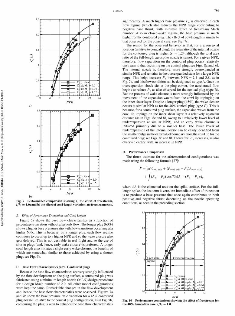
b) Fig. 9 Performance comparison showing a) the effect of freestream,
l=ht � 1:0; and b) the effect of cowl-length variation; no freestream case.
NPR
Cf(x
)
0 2 4 6 8 10 120.8
0.9
1
1.1
1.2
1.3
Cf(i): idealCf(x); 100% spikeCf(x): 40% spike; M∝ = 0.0Cf(x): 40% spike; M∝ = 0.94Cf(x): 40% spike; M∝ = 1.57
Closed-wake regimeOpen-wakeregime
Fig. 10 Performance comparison showing the effect of freestream for
the 40% truncation case; l=ht � 1:0.
VERMA 789
Dow
nloa
ded
by U
NIV
OF
CA
LIF
OR
NIA
LO
S A
NG
EL
ES
on M
ay 2
, 201
4 | h
ttp://
arc.
aiaa
.org
| D
OI:
10.
2514
/1.4
0302

The coefficient of thrust of a nozzle is given by [27]
Cf�x� � F=�AtP0j�
For an ideal nozzle (Pe � Pa), the optimum coefficient of thrust isgiven by
Cf�i� ��
2k2
k � 1
�2
k 1
�k1k�1�1 �
�PePoj
�k�1k
��0:5
It can be seen that, for the ideal case, theCf value is dependent ongas property k and the pressure ratio across the nozzle and not on thetype of nozzle.
Figure 9a shows a comparison of theCf variation with NPR for nofreestream condition and with cowl-length variation. The thrust ineach case was estimated using the wall pressure distribution andintegrating it over the conical surface area of the spike. Theuncertainty in the evaluation of Cf is approximately�0:3% at eachtest NPR. A comparison of the estimatedCf value for the test cases isalso made with an ideal nozzle that changes its area ratio with achange in NPR. It can be seen that up to NPR 5 the two test casesshow similar performance. Beyond NPR 5, the two curves begin todepart. Note that, for all test cases with NPR � 6, flow separationdoes not occur on the plug and, therefore, relates theflowcondition tomain stage operation. The curve for the cowl length of 0.5 showslower performance relative to the cowl length of 1.0. The differenceis about 2% (of Cf) at NPR of 7.25. The probable reason is thehigher contribution from the momentum term for l=ht � 1:0 thatoverweighs the benefits of higher wall pressures on the spike forl=ht � 0:5, especially at higher NPR.
The effect of freestream flow on the nozzle performance can beseen in Fig. 9b. The presence of freestreamflowmodifies the externaljet boundary originating from the cowl lip significantly and, hence,the flow development on the spike if constant chamber pressure,P0j,is maintained, which is relevant to real flight conditions. However, ifsimilar NPR are to be maintained to evaluate and compare the thrustperformance, then a lesser mass flow is required from the nozzle (dueto lowerP0j required tomaintain similar NPRasPa decreaseswith anincreasingM1) than for a nozzlewith no freestream condition so that
the momentum thrust contribution from the internal nozzle isrelatively less with freestream flow. In either case, a reduction in netthrust results with an increasing NPR, as seen in Fig. 9b.
The truncated spike shows no change in theCf value, with respectto that for the full-length spike, up to the point at which the flowundergoes a flow transition from an open-wake to close-wakeregime; see Fig. 10. At this point, a sudden drop in the Cf value isobserved, after which the Cf value once again increases with anincrease in NPR. For different freestream conditions, a change in theCf value trend is seen to occur at the NPR for which the base regioncloses for each test case. After this flow transition, a reduction in theCf value is apparent between the truncated and full-length cases.
E. Spectral Analysis
Figures 11a and 11b show the schlieren picture of the type B flowcondition (NPR� 3:1) on the full-length conical aerospike (withoutfreestream) and the corresponding time history of a wall pressuresignal in the intermittent separation region, respectively. The large-scale streamwise oscillatory motion or “flapping” of the shock wavecan be easily identified; see Fig. 11b. The high level in wall pressure,P2, is captured when the “foot” of the shock wave is upstream of thetransducer, whereas level P1 is captured when the shock wavetranslates downstream of the transducer location. Figures 11c and11d show the power spectra of wall pressure fluctuations in theundisturbed boundary layer and in intermittent separation regions,respectively. A 1500 Hz peak in frequency can be seen in the regionof separation, as in Fig. 11d, and downstream (not shown). Theseparation region also shows fluctuations in the 200–800 Hz range,suggesting highly unsteady flow conditions near separation shock.
IV. Conclusions
An experimental investigation has been carried out to study theperformance characteristics of an annular conical aerospike nozzle(full length and 40% truncation). For no freestream condition, theperformance of a full-length conical aerospike nozzle differs fromthe ideal case by about 3–4% (of Cf) at almost all NPR tested. A
0.00
0.05
0.10
0.15
0.20
0.25
0.30
0 1000 2000 3000 4000 5000
Frequency (Hz)
G(f
)(p
si2 /H
z)
0.000
0.002
0.004
0.006
0.008
0.010
0 1000 2000 3000 4000 5000
Frequency (Hz)
G(f
)(p
si2 /H
z )
Overexpansion shock
Kulite locations Spike surface
c)
X/L = 0.276
d)
X/L = 0.343
a)
Overexpansion shock from internal nozzle
0.15
0.2
0.25
0.3
0.35
0.4
0 0.005 0.01 0.015 0.02 0.025 0.03
time (s)
Pw
/Poj
b)
X/L = 0.343 Shock passages
P1
P2
Fig. 11 Flow condition on a full-length conical aerospike nozzle: a) schlieren picture showing the shock structure details in a type B flow; b) time history
of the wall pressure signals in an intermittent region of separation forNPR� 3:1, and c) and d) power spectral density in the separation region (first twolocations).
790 VERMA
Dow
nloa
ded
by U
NIV
OF
CA
LIF
OR
NIA
LO
S A
NG
EL
ES
on M
ay 2
, 201
4 | h
ttp://
arc.
aiaa
.org
| D
OI:
10.
2514
/1.4
0302

reduction in cowl length to 0.5 further reduces the performance of thenozzle. In the presence of freestream conditions, the performance ofthe tested configurations further drops by 3% at the highest NPR.
Truncating the spike does not affect the nozzle performanceexcept when the flow undergoes a transition from an open-wake toclosed-wake regime. After this, although the Cf value continues toincrease with an increase in NPR, a drop in performance relative tothe full-length spike of about 3% is observed. Contouring the plugmodifies the flowfield considerably, both on the plug and in the base-wake region, with significant improvement in overall base thrustcontribution and minimum time spent under negative base thrustcontribution.
Flow separation at low NPR indicates highly unsteady flowconditions on the full-length conical spike, which can result inundesirable lateral forces/side loads. To avoid this condition, it ispreferred to use shorter plug nozzles so that they can switch to aclosed-wake regime at lower altitudes. This can be further achievedby properly designing the plug contour and plug corner and by usingan appropriate base-bleed system.
Acknowledgments
The author wishes to thank the Aeronautics Research andDevelopment Board, India, for funding the project. The technicalsupport of Rajshekhar Gowda during aerospike model design andfabrication and of A. Narayanswamy and V. Biju of the Base Flowfacility at the National Aerospace Laboratories during the testcampaigns is gratefully acknowledged. Many thanks to FrancescoNasuti of the University of Rome “La Sapienza,” Tomita Takeo ofthe Japan Aerospace Exploration Agency, and Joesph Ruf of theNASAMarshall Space Flight Center for the useful discussions I hadwith them over e-mail during the planning and execution of thiswork.
References
[1] Hagemann, G., Immich, H., Nguyen, T. V., and Dumnov, G. E.,“Advanced Rocket Nozzles,” Journal of Propulsion and Power,Vol. 14, No. 5, Sept.–Oct. 1998, pp. 629–634.
[2] Stark, R., Boehm, C., Haidn, O. J., and Zimmermann, H., “Cold FlowTesting of Dual-Bell Nozzles in Altitude Simulation Chamber,”European Conference for Aerospace Sciences (EUCASS), 2006.
[3] Hagemann, G., Frey, M., and Koeschel, W., “Appearance of RestrictedShock Separation in Rocket Nozzles,” Journal of Propulsion and
Power, Vol. 18, No. 3, 2002, pp. 577–584.doi:10.2514/2.5971
[4] Oestlund, J., Damgaard, T., and Frey, M., “Side-Load Phenomena inHighly Overexpanded Rocket Nozzles,” Journal of Propulsion and
Power, Vol. 20, No. 4, 2004, pp. 695–704.doi:10.2514/1.3059
[5] Verma, S. B., Stark, R., and Haidn, O., “Relation Between ShockUnsteadiness and the Origin of Side-Loads in a Thrust OptimizedParabolic Rocket Nozzle,” Aerospace Science and Technology,Vol. 10, No. 6, Sept. 2006.
[6] Verma, S. B., and Oskar, H., “Study on Restricted Shock SeparationPhenomena in Rocket Nozzles,” AIAA Paper 2006-1431, 2006.
[7] Manski, D., Hagemann, G., Frey, M., and Frenken, G., “Optimizationof Dual Mode Rocket Engine Nozzles for SSTO Vehicles,”IAF 98-S.3.08.
[8] Berman, K., and Crimp, F. W., Jr., “Performance of Plug-Type RocketExhaust Nozzles,” American Rocket Society Journal, Jan. 1961,
pp. 18–23.[9] Rao, G. V. R., “Recent Developments in Rocket Nozzle
Configurations,” American Rocket Society Journal, Nov. 1961,p. 1488.
[10] Angelino, G., “Approximate Method for Plug Nozzle Design,” AIAAJournal, Vol. 2, No. 10, Oct. 1964, pp. 1834–1835.doi:10.2514/3.2682
[11] Huzel, D. K., and Huang, D. H., “Design of Liquid Propellant Rocket
Engines,” NASA Science and Technical Information Office,Washington D.C., 1967, pp. 89–95.
[12] Wasko, R. A., “Performance of Annular Plug and Expansion-Deflection Nozzles Including External Flow Effects at TransonicMachNumbers,” NASA TN D-4462, April 1968.
[13] Humphreys, R. P., Thompson, H. D., and Hoffmann, J. D., “Design ofMaximum Thrust Plug Nozzles for Fixed Inlet Geometry,” AIAA
Journal, Vol. 9, No. 8, Aug. 1971, pp. 1581–1587.doi:10.2514/3.49960
[14] Migdal, D., “Supersonic Annular Nozzles,” Journal of Spacecraft andRockets, Vol. 9, No. 1, Jan. 1972, pp. 3–6.doi:10.2514/3.61623
[15] Sule, W. P., and Mueller, T. J., “Annular Truncated Plug NozzleFlowfield and Base Pressure Characteristics,” Journal of Spacecraft
and Rockets, Vol. 10, No. 11, 1973, pp. 689–695.doi:10.2514/3.61949
[16] Hall, C. R., Jr., and Mueller, T. J., “Exploratory Analysis ofNonuniform Plug Nozzle Flowfields,” Journal of Spacecraft and
Rockets, Vol. 9, No. 5, 1972, pp. 373–342.doi:10.2514/3.61684
[17] Ruf, J. H., and McConnaughey, P. K., “The Plume Physics BehindAerospike Nozzle Altitude Compensation and Slipstream Effect,”AIAA Paper 97-3217, 1997.
[18] Fick, M., and Schmucker, R. H., “Performance Aspects of Plug ClusterNozzles,” Journal of Spacecraft and Rockets, Vol. 33, No. 4, July–Aug. 1996, pp. 507–512.doi:10.2514/3.26792
[19] Rommel, T., Hagemann, G., Schley, C.-A., Kruelle, G., and Manski,D., “Plug Nozzle Flowfield Analysis,” Journal of Propulsion and
Power, Vol. 13, No. 5, Sept.–Oct. 1997.[20] Hagemann, G., Immich, H., and Terhardt, M., “Flow Phenomena in
Advanced Rocket Nozzles—The Plug Nozzle,” AIAA Paper 98-3522,1998.
[21] Dumnov, G. E., Nikulin, G. Z., and Ponomaryov, N. B., “Investigationof Advanced Nozzles for Rocket Engines,” Space Rocket Engines andPower Plants, Vol. 4, No. 142, NIITP, 1993 (Published in Russian).
[22] Tomita, T., Tamura, H., and Takahashi, M., “An ExperimentalEvaluation of Plug Nozzle Flowfield,” AIAA Paper 96-2632, 1996.
[23] Ito, T., Fujii, K., and Hayashi, A. K., “Computations of AxisymmetricPlug-Nozzle Flowfields: Flow Structures and Thrust Performance,”Journal of Propulsion and Power, Vol. 18, No. 2, 2002, pp. 254–260.doi:10.2514/2.5964
[24] Yu, L., Zhengke, Z., Wuye, D., Jingsheng, Z., Shouen, Z., Xianchen,C., and Zhengpeng, Z., “Experimental and Numerical Studies onAerospike Nozzles,” AIAA Paper 99-2340, 1999.
[25] Wuye, D., Yu, L., and Xianchen, C., “Simulated Tests of AerospikeNozzle and Data Acquisition System,” Journal of Propulsion
Technology, Vol. 21, No. 4, 2000, pp. 85–88.[26] Norris, G.,“Solid Performance for Aerospike,” Flight International,
27 April–3 May 2004, p. 28.[27] Sutton, G. P., and Biblarz, O., Rocket Propulsion Elements, 7th ed.,
Wiley Interscience, New York, 2000.
K. FrendiAssociate Editor
VERMA 791
Dow
nloa
ded
by U
NIV
OF
CA
LIF
OR
NIA
LO
S A
NG
EL
ES
on M
ay 2
, 201
4 | h
ttp://
arc.
aiaa
.org
| D
OI:
10.
2514
/1.4
0302