performance based design for self-compacting structural...
TRANSCRIPT

1313131313
SP-228—2
PPPPPerererererffffformormormormormancancancancance Be Be Be Be Baaaaased Dsed Dsed Dsed Dsed Deeeeesssssignignignignignfffffor or or or or SelfSelfSelfSelfSelf-C-C-C-C-Compompompompompactinactinactinactinacting g g g g StructStructStructStructStructurururururalalalalal
High-High-High-High-High-StrStrStrStrStrenenenenengggggth Cth Cth Cth Cth Conconconconconcrrrrreteteteteteeeee
bbbbbyyyyy H. OH. OH. OH. OH. Okkkkkamuramuramuramuramura, K. Ma, K. Ma, K. Ma, K. Ma, K. Maekaekaekaekaekaaaaawwwwwa, and a, and a, and a, and a, and TTTTT. Mi. Mi. Mi. Mi. Mishimshimshimshimshimaaaaa
Synopsis:Synopsis:Synopsis:Synopsis:Synopsis: This paper contains an historical review of self-compacting concreteclarifies and the original concept. Further, combinations of self-compacting concrete forhigh strength and durability are discussed in relation to structural concrete design,construction and maintenance, and recent development of performance-based designcodes and manuals for SCC. On the competitiveness in industries, life-cycle cost isestimated for sustainable development of the infrastructure.
Keywords: construction; durability; high-strength; life cycle cost;maintenance; performance assessment; self-compacting concrete;structural concrete

1414141414 Okamura et al.Okamura et al.Okamura et al.Okamura et al.Okamura et al.Hajime OKAMURA is currently the President and a Professor of Kochi University of
Technology, Japan. He is a former Dean of Engineering School of The University of Tokyo
and the President of Japan Society of Civil Engineers.
Koichi MAEKAWA is a Professor of Department of Civil Engineering at The University of
Tokyo, Japan. He received his doctorate degree from The University of Tokyo in 1985.
Tetsuya MISHIMA is currently a manager at the Structural Engineering Section of
Technical Research Institute, Maeda Corporation.
INTRODUCTION
Since the breakthrough of self-compacting concrete (SCC) in 1988, its practical
application to structural concrete has been driven in world construction industries.
Meanwhile, additional higher performances, such as strength, durability and
environmental friendliness, have been coupled with the self-compacting feature. Structural
and material design methods have been also proposed to rationally extract the potential of
SC based concrete. This paper summarizes SCC development in the past decades and
introduces the updated performance-based design of high strength structural concrete with
self-compacting nature.
SCC development history in the Japanese construction industry is illustrated in Figure
1. In early 1980s, shortened structural life of reinforced concrete drew public interest and
criticism. Insufficient workmanship and compaction were recognized as primary causes of
these defects. This was the background to make the first move towards self-compacting
concrete. We accepted it as true that SCC may ensure the inherent capability of concrete
composites in practice. Hence, no compaction is the best way to achieve material potential.
This was the first message to the industry and was given at the occasion of Japan Cement
Association Meeting in 1986. This message presented by the first author was regrettably
thought of as just a vision.
Before the first prototype innovation, multi-particle physics was chiefly investigated to
clarify the dynamic segregation of the liquid matrix - particle suspension system1), 2)
. Here,
fresh concrete was firmly understood as a multi-sized particle assembly as clearly figured
out by T. C. Powers3)
. The frictional stress transfer was also studied for segregation-free
concrete as an analogy of SCC.
After the 1988 SCC discovery at the University of Tokyo, chemo-physical assessment of
super-plasticizer was challenged for the mix design procedure4)
, which was issued in 1991.
Next, the production manual and quality control system were developed for ready mixed
concrete manufacturing and practical applications5)
. The first terminology for this
compaction free concrete was high performance concrete (HPC). In those days, some
confusion occurred in academia as HPC was chiefly used for high strength concrete. Then, to
elucidate the original concept of development, the terminology SCC was introduced. Main
focus was directed to high quality concrete that can be achieved in real structures.
Since Hanshin-Awaji Great Earthquake in 1995, high seismic structural performance
has been required in Japan. In concert, life cycle capacity of infrastructures has become the
great social demand. In fact, with increases in maintenance costs for existing structures,

High-High-High-High-High-StrStrStrStrStrenenenenengggggth/High-Pth/High-Pth/High-Pth/High-Pth/High-Perererererffffformormormormormancancancancance Ce Ce Ce Ce Conconconconconcrrrrreteteteteteeeee 1515151515self-compacting, high-strength and durable concrete has been drawing attention as an
engineering solution. At present, this combination is denoted as super quality concrete
(SQC) in Japan. Based on this activity, a performance-based design guideline for structural
SQC was issued in 2000 and approved by Concrete Committee of the Japan Society of
Civil Engineers (JSCE) (Figure 1). With this, the initial cost of structures can be equivalent
to that of conventional reinforced concrete (RC) in spite of their increased durability and
greater seismic resistance with much less life-cycle cost.
This paper presents an outline of the design and management to rationally realizing
SCC as “high performance structural concrete.”
SIMILARITY OF SCC AND HIGH STRENGTH CONCRETE in 1940
There is a surprising similarity between the 1988 innovated self-compacting concrete
and the high-strength concrete6)
developed by Dr. T. Yoshida in 1940 at University of
Tokyo. After the innovation of SCC in 1988, the volumetric mix proportions of SCC were
found to be so close to this old time high-strength concrete (HSC) of more than 110 MPa as
shown in Figure 2. This HSC was mainly utilized for precast concrete railway tunnel
linings in the 1940s. In order to obtain the high strength, compression force was first
applied to fresh concrete carefully encased inside the steel forms and the mixed water was
squeezed out through the voids of the forms. Then, the water - cement ratio by weight was
reported to be 0.22 from the initial 0.31.
For efficiently squeezing water, applied compressive stress shall be directly transferred
to the cement paste phase residing inside the voids of fine and coarse aggregates as shown
in Figure 2. The coarse aggregate phase should not bear the contact compression so that
the mortar phase may carry the total stress in between the coarse aggregates. In concert, the
sand particle assembly shall be loosely dispersed for conveying total compression to the
cement paste phase. Although this multi-scale stress transfer is rather volumetric for
long-standing high-strength concrete, the design concept of SCC in terms of shear flow is
basically the same.
It can be said that the matching mix proportions are not mere coincidence but they
result from the logic no matter how different the deformational modes are. The authors
believe that if there were a super-plasticizer about 70 years ago, Dr. T. Yoshida would be
the innovator of SCC, because old high strength concrete mix proportion as shown in
Figure 2 was verified to turn into SCC when we use the same properties of sands and
gravels with the current super-plasticizer. Nowadays, the old high-strength concrete
continues to serve in the undersea railway tunnel facilities since 1940, and there is no
problem even without maintenance for more than 60 years. This is evidence of the
possibility of SQC with a long service life.
SELF-COMPACTING HIGH-STRENGTH CONCRETE (SQC)
Mix Proportions and Concrete Materials
The highly flowing character of SCC specified by the SQC design guideline is obtained

1616161616 Okamura et al.Okamura et al.Okamura et al.Okamura et al.Okamura et al.by a large dosage of powder and the use of no viscous admixture agent. Typical mix
proportions specified in the guideline are listed in Table 1. The SQC design guideline
specifies the quality requirements of 1) self-compacting feature, 2) water-binder ratio less
than 0.40 by weight, 3) autogenous shrinkage less than 200 x 10-6
at 28 days, 4) concrete
strength of 60 to 100 N/mm2
at 56 days. The major concrete constituent materials are
described as follows: cement: belite rich, cement with admixtures or low-heat when the
unit cement content becomes high, aggregate: durable hard crushed stone with stability
against alkali-aggregate reaction due to the higher unit cement content, admixtures: air
entraining water reducing chemicals to have air content around 6% when resistance to
freeze-thaw cycles is required.
Mechanical Properties of High-Strength Deformed Steel Bars
Currently, the use of high-strength deformed steel bars is growing, especially for RC
tall buildings and high bridge piers. Thus, the SQC design guidelines include high-strength
reinforcement in order to combine high performance steel and concrete for structural
enhancement against earthquakes. The mechanical properties are shown in Table 2 and
typical stress-strain relationship is shown in Figure 3.
Materials and Construction Costs
The main materials used for SQC structures are high-strength steel (USD685 or other
type) and SCC. At present, the unit cost of high-strength steel is slightly more than double
that of ordinary electric furnace steel. The unit cost of SQC is 1.5 to 2.5 times the ordinary
concrete cost and varies greatly from region to region. Material costs are needlessly high in
Japan owing to the cartel market structure.
The SQC Association conducted trial structural designs and estimated costs under
various conditions. Some estimates exhibited lower construction costs even though the high
expense of SQC is inevitable in Japan, because smaller volumes of concrete can be
sufficiently placed and less quantities of excavated soil are produced if the cross section of
the structure can be reduced. Figure 4 shows a cost comparison for bridge piers and box
culverts. SQ structural concrete is competitive although SQ material costs much more. This
is the reason why SQC design codification is demanded on a performance basis.
STRUCTURAL PERFORMANCES
Seismic Resistance
(1) Experimental outline--Kondoh et al. reported the results of reversed cyclic loading
to verify the ductility of SQC column members7), 8)
. The materials stated in the previous
section were applied to specimens subjected to reversed cyclic loading. Table 3 lists the
properties of specimens used in the laboratory experiments. Figure 5 shows an external
view of the specimen with the cross sectional dimensions and loading points.
Major parameters used in the experiment were the longitudinal reinforcement ratio and
the shear capacity ratio defined by V·L/M, where V denotes the shear capacity, L, the shear

High-High-High-High-High-StrStrStrStrStrenenenenengggggth/High-Pth/High-Pth/High-Pth/High-Pth/High-Perererererffffformormormormormancancancancance Ce Ce Ce Ce Conconconconconcrrrrreteteteteteeeee 1717171717span and M, the flexural capacity. The axial force was set at approximately 10% of the
design axial capacity of each specimen. For specimen No. 9 with a reduced cross sectional
area, a mean axial stress of 4.69 N/mm2
was applied to maintain comparison with No. 0
under the same axial force.
(2) Experimental results--Figure 6 shows flexural moment displacement relations for
typical specimens. Specimen No. 1 has a longitudinal reinforcement ratio equivalent to that
of No. 0, and was made of high-strength material. The experimental result shows that the
yield strength My of specimen No. 1 becomes larger than that of No. 0 in proportion to the
increase in the yield strength of longitudinal steel, but that the ultimate displacement is
almost the same for both cases. It is thus found that an increase in the strength of column
members is possible while maintaining their ductility, and that SQC column members may
absorb energy and resist seismic forces no less than ordinary reinforced concrete members.
Specimen No. 9, which was designed to have a reduced cross sectional area to provide
a flexural capacity equivalent to that of No. 0, possesses a ductility equivalent to or greater
than that of No. 0. Thus, SQC members can maintain their strength and ductility even after
their cross sectional area is reduced to 60 to 70% of that of ordinary reinforced concrete
members. Then, it is possible to reduce the dead weight of the structure and to elevate
seismic resistance, simultaneously. All three specimens as shown in Figure 5 have the
same shear capacity ratio of 1.5. For lateral hoops, D10s (SD345s) were placed at intervals
of 6 cm, D10s (USD785s) at intervals of 6 cm, and D10s (USE785s) at intervals of 9 cm in
specimen Nos. 0, 1 and 9, respectively.
(3) Ductility--Figure 7 shows the relation of the ultimate rotational capacity (mean
drift angle) and the shear capacity ratio. It was reported that specimen No. 9 with a shear
span to depth ratio, which slightly differs from the other specimens, has slightly higher
ductility but that a certain correlation is observed between shear capacity ratio and the
ultimate rotational angle for the other specimens, and could be expressed by equation (1).
The equation seems fully applicable as a design formula for simply identifying the ductility
of SQC members with a shear span to depth ratio (approximately 3.0) equivalent to that of
the specimen shown in this paper.
( ) 018.0018.0 +⋅
⋅=
M
LV
u
θ (1)
The Seismic Design Standards for Railway Structures adopt design methods that take
disaster-induced damage levels into consideration. If the Design Standards are applicable
to SQC members, practical design using SQC structural characteristics is possible. For
example, the yield strength can be set at a high level by using high-strength materials
without over-use of steel. Then, it is easy to design structures to control the degree of
disaster-induced damage by considering how important the target structure is. The
correlation of the damage level and the load-displacement relation is shown in Figure 8.
Figure 9 shows a comparison between experimental and calculated results for specimen
No. 1. The formula in the Design Standards evaluates ductility of SQC members at
respective damage levels fairly well. It may be confirmed that the Design Standards are
applicable to SQC members, too.

1818181818 Okamura et al.Okamura et al.Okamura et al.Okamura et al.Okamura et al.Shear Strength
The material strength and member shear capacity are not proportional. At present,
rational design formulae are being developed for simply evaluating the shear capacity of
structural reinforced concrete members using high-strength materials, although the use of
nonlinear finite element based assessment is advanced especially for size effect 9)
. Recently
much research has been performed and data have been accumulated.10), 11)
The proposed
design formulae in detail is explained in reference 12.
Strength of Lap Splice
Ito et al. studied the basic anchorage length of SQC members using beam specimens
with lap splices along the length in a region of constant bending moment.13)
They
compared the experimental bond strength with the calculated one in the Standard
Specifications for Design and Construction of Concrete Structures14)
, and suggested that
the present bond strength should be reduced slightly for SQC members. Table 4 lists the
specimen tests carried out by Ito el al. and Figure 10 shows the details of the specimens.
Table 5 is a list of experimental results. The experimental values were below the
calculated ones by about 10%. Then, equation (2) is proposed for calculating the bond
strength of SQC while considering a reduction factor β of 0.89, a mean value among all
specimens. It is confirmed that setting the material factor for bond strength γ c at 1.3 may
ensure safety as for lap splice strength as shown in Figure 11.
( ) 3.1,89.0,'28.03/2
==⋅=
cccboff γβγβ (2)
DURABILITY AND LIFE-CYCLE ASSESSMENT
Durability simulation of structural concrete is one of challenges in concrete science
and technology15)
and practical application to life cycle assessment is also expected16)
. The
major determinant of durability of reinforced concrete structures is the corrosion of
reinforcement and embedded steel. Steel corrosion is generally accelerated by concrete
cracking, carbonation, chloride ion penetration, erosion by acid rain, freezing and thawing
cycles, chemical erosion and alkali-aggregate reaction. In turn, the corrosion may
accelerate cracking and cover concrete spalling. Together, and they mutually quicken
corrosion itself. Thus, quantitative risk assessment of concrete deterioration due to these
factors is necessary for ensuring the long-term service life of durable structural concrete.
Outlined below are the results of experiments for the resistance to carbonation, freezing
and thawing cycles and acid rain for self-compacting, high-strength and highly durable
concrete. The formula for predicting deterioration is also described17), 18), 19)
in this section.
The SQC Association has been the driving force in establishing SQC guidelines in
practice.
Carbonation
As self-compacting, high-strength and highly durable concrete has a water-binder ratio

High-High-High-High-High-StrStrStrStrStrenenenenengggggth/High-Pth/High-Pth/High-Pth/High-Pth/High-Perererererffffformormormormormancancancancance Ce Ce Ce Ce Conconconconconcrrrrreteteteteteeeee 1919191919less than 0.40, the hardened concrete is normally dense and has greater resistance to
carbonation than ordinary concrete. Figure 12 shows the result of an accelerated
carbonation test for SQC with a water-binder ratio less than 0.40. The accelerated
carbonation was started at 56 days at a carbon dioxide concentration of 5%. The
compressive strength at the beginning of the experiment is indicated along the horizontal
axis, and the depth of carbonation after 26 weeks of acceleration is shown on the vertical
axis. The figure shows that the greater the compressive strength is at the beginning, the
more quickly the depth of carbonation decreases.
According to Recommendations for Design and Construction Practice of High
Durable Concrete of the Architectural Institute of Japan, a carbonation depth of 30 mm in
service for 500 years under normal conditions corresponds to 12 mm after 26 weeks of
accelerated carbonation.
A carbon dioxide concentration of 5% during the experiment was converted to a value
in the air and the coefficient of carbonation rate was obtained for practical use. The
relationship of the coefficient to the effective water-binder ratio is shown in Figure 13. The
coefficient,α , of carbonation rate for self-compacting, high-strength and highly durable
concrete α can be estimated by,
( )year/mm'63.138.0 BW+−=α (3)
where, W/B' = effective water-binder ratio = W/(Cp+k·A
d),
W = unit content of water (kg/m3
),
B' = unit content of effective unit binder (kg/m3
),
Cp = unit content of Portland cement (kg/m
3
),
Ad = unit content of admixture (kg/m
3
),
K = constant determined by the type of admixture,
For fly ash k=0, for iron-blast furnace slag powder k=0.7, for silica fume k=0.
Acid Rain
When acid rain acts on concrete, the hydrogen ion in the acid rain reacts with the
hydroxide ion in the pore solution of concrete, the alkalinity of concrete is lost, and
hydro-oxide ion concentration by pH is decreased. When acid rain has a great impact on
concrete, the calcium silicate hydrate that constitutes the cement paste gets vulnerable to
decomposition under much lower pH environment. Then, embrittlement causes erosion of
the concrete texture. Other types of ions contained in acid rain may also have adverse
effects. For example, the sulfate ion is likely to cause expansion of the concrete and lead to
mechanical deterioration.
An accelerated test was conducted to evaluate the resistance of SCC against acid rain
under the conditions listed in Table 6. The results are shown in Figure 14. The figure
indicates that the erosion depth is proportional to the duration of acid rain, and that the
depth after 50 cycles is about 1 mm regardless of the mix proportions. As a result of the
accelerated test, the eroding rate C0 was estimated at 1/50 mm/day, or 7.30 mm per year,
based on the fact that the eroding time per cycle was one day. The value of pH was set 3.0
and it was assumed that the erosion depth is proportional to the acid rain concentration.
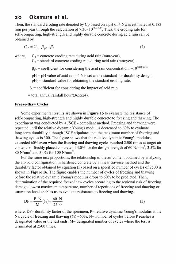
2020202020 Okamura et al.Okamura et al.Okamura et al.Okamura et al.Okamura et al.Then, the standard eroding rate denoted by Cp based on a pH of 4.6 was estimated at 0.183
mm per year through the calculation of 7.30×10(3.0-4.6)
. Thus, the eroding rate for
self-compacting, high-strength and highly durable concrete during acid rain can be
obtained by,
tphpdCC ββ ⋅⋅= (4)
where, Cd = concrete eroding rate during acid rain (mm/year),
Cp = standard concrete eroding rate during acid rain (mm/year),
βph
= coefficient for considering the acid rain concentration, =10(pH0-pH)
pH = pH value of acid rain, 4.6 is set as the standard for durability design,
pH0 = standard value for obtaining the standard eroding rate,
βt = coefficient for considering the impact of acid rain
= total annual rainfall hour/(365x24).
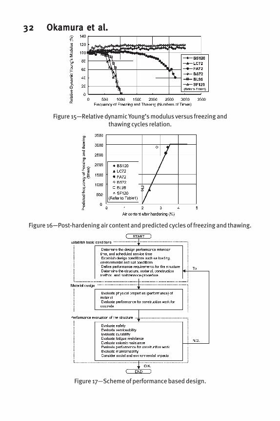
Freeze-thaw Cycles
Some experimental results are shown in Figure 15 to evaluate the resistance of
self-compacting, high-strength and highly durable concrete to freezing and thawing. The
experiment was conducted by a JSCE - compliant method. Freezing and thawing were
repeated until the relative dynamic Young's modulus decreased to 60% to evaluate
long-term durability although JSCE stipulates that the maximum number of freezing and
thawing cycles is 300. The figure shows that the relative dynamic Young's modulus
exceeded 60% even when the freezing and thawing cycles reached 2500 times at target air
contents of freshly placed concrete of 4.0% for the design strength of 60 N/mm2
, 3.5% for
80 N/mm2
and 3.0% for 100 N/mm2
.
For the same mix proportions, the relationship of the air content obtained by analyzing
the air-void configuration in hardened concrete by a linear traverse method and the
durability factor obtained by equation (5) based on a specified number of cycles of 2500 is
shown in Figure 16. The figure enables the number of cycles of freezing and thawing
before the relative dynamic Young's modulus drops to 60% to be predicted. Then,
determination of the required freeze/thaw cycles according to the regional risk of freezing
damage, lowest maximum temperature, number of repetitions of freezing and thawing or
saturation level enables us to evaluate resistance to freezing and thawing.
( )
2500
N60
%
M
NP
DF
⋅
=
⋅
= (5)
where, DF= durability factor of the specimen, P= relative dynamic Young's modulus at the
Nth
cycle of freezing and thawing (%) =60%, N= number of cycles before P reaches a
designated value or the test ends, M= designated number of cycles where the test is
terminated at 2500 times.

High-High-High-High-High-StrStrStrStrStrenenenenengggggth/High-Pth/High-Pth/High-Pth/High-Pth/High-Perererererffffformormormormormancancancancance Ce Ce Ce Ce Conconconconconcrrrrreteteteteteeeee 2121212121DESIGN EXAMPLES
Draft Design and Construction Guideline
The SQC Association requested the Concrete Committee of the Japan Society of Civil
Engineers to review and develop a new authorized design and construction guideline
focused on performance assessment of SQC based upon the voluntary draft for design and
construction of structural SQC prepared by the Association in 1996. After two-years of
serious discussion and enhancement, the new guideline was published in March 2001 by
JSCE. It consists of five volumes: I. Design and construction guideline focused on
performance evaluation, II. Design manual, III. Construction manual, IV. Maintenance and
V. Appendix -Design guides and examples-. The configuration of the guideline emphasizes
performance verification and is on the basis of JSCE Standard Specifications for Design
and Construction of Concrete Structures.
Chapter I only describes conceptual design and construction issues, basically
independent of specific technical knowledge. The subsequent chapters describe the latest
technology, but should be revised step by step whenever new progress is obtained. The
second and the following chapters are mutually related. For example, the descriptions on
maintenance presuppose that design and construction comply with the contents of Chapters
II and III.
Flow of Design and Design Conditions
This section outlines an example of design presented in the appendix to the guideline.
The flow of a design example is shown in Figure 17. The review process is divided into
two major phases: material design and performance evaluation of the structure. In material
design, targeted physical properties (characteristic values) are specified and performance
for construction work is evaluated. Performance evaluation of the structure consists of the
evaluation of performance requirements for safety, serviceability, durability and seismic
resistance.
In design focused on performance evaluation, design conditions are defined first, and
evaluated to check whether they satisfy the design requirements of the target structure. A
fast finding of the design conditions that satisfy performance requirements in all terms is
the key to work efficiency. The discussion of the sample design emphasizes the procedure
for evaluating the specified design conditions, but does not refer to the method for
efficiently establishing the design conditions that pass assessment. The major design
conditions demanded for the sample design are listed as (1) design period of performance
retention assurance: 100 years, (2) substantially expected period of service: 300 to 500
years: for superstructure, (3) prestressed concrete five-span continuous bridge with hollow
slabs, (4) substructure: wall piers and pile foundations (cast-in-place piles), (5)
environmental conditions: inland, coastal or cold area, (6) (coastal area is defined within
500 m from the coast line), (7) concrete: LC72 (f'ck
=60 N/mm2
), (8) longitudinal
reinforcement: USD685, transverse reinforcement: USD785.

2222222222 Okamura et al.Okamura et al.Okamura et al.Okamura et al.Okamura et al.Results of Performance Evaluation
As an example of a structure that satisfies performance requirements for safety and
seismic resistance, the dimensions and shape of substructure are shown in Figure 18. As
for construction work, the second-level self-compaction is required in view of density of
reinforcement arrangement. The LC72 mix proportion satisfies all the standard values
required for the second level, and thus passes assessment. It is verified that the structure
with the concrete cover specified in Table 7 satisfies performance requirements for
serviceability and durability in the inland and cold areas. In a coastal area, however, the
structure has insufficient resistance to salt attack even if the LC72 mix proportion be used.
In this case, some measures are required such as providing a concrete cover of about 95
mm in the bridge pier or applying surface protection by coating.
Life Cycle Cost – Comparison of SQC and Conventional Structural Concrete -
In order to clarify the competitiveness of self-compacting high strength concrete, life
cycle cost was compared with 9 design details of a RC bridge pier located close to the sea
(See Figure 19) 20)
. Here, life cycle cost is defined as the sum of initial construction cost
and estimated maintenance expense. The recycle cost is not included and no discounting
rate is set up. For estimating the maintenance cost, repair and rebuilt expenses by currency
are calculated in terms of steel corrosion and probabilistic earthquake induced damage.
The corrosion risk assessment was conducted with following equations of the JSCE
Standard Specifications21)
according to the cover depth and the quality of concrete.
( )diffusionofequation2
2
x
u
D
t
u
d
∂
∂
=
∂
∂
(6)
( )standardjudging213
limkg/m.CC
d=≥ (7)
where, u = Density of chloride ion (kg/m3
) at x=0, u=C0
t = time (s)
x = distance from concrete surface (cm)
Dd = Diffusion coefficient of chloride ion (cm
2
/s)
C0 = Density of chloride ion at concrete surface (kg/m
3
)
Cd = Density of chloride ion at steel bar (kg/m
3
)
Clim
= Corrosion limit density of chloride ion (kg/m3
)
The repair cost to recover the function after earthquake can be estimated with the
possibility of seismic event of different magnitudes and corresponding damage magnitude
of the structure. The damage level can be computed by conducting nonlinear dynamic
analysis under the estimated seismic action. If much reinforcement is placed, the recovery
cost may be less even under great seismic loads but the initial cost will be increased. If we
itemize high quality concrete, larger initial cost will be demanded, but the maintenance
cost can be compressed. Then, the material / structural capability, which have much to do
with initial cost, are trade-offs of maintenance cost.

High-High-High-High-High-StrStrStrStrStrenenenenengggggth/High-Pth/High-Pth/High-Pth/High-Pth/High-Perererererffffformormormormormancancancancance Ce Ce Ce Ce Conconconconconcrrrrreteteteteteeeee 2323232323Here, nine cases of design details are discussed as listed in Table 8, and the
corresponding LCC estimation is lined up in Table 9. All cases satisfy the requirements of
the design code specification for road bridges in Japan. SQC design exhibits a little bit
higher initial cost than others as an extremely high unit price of self-compacting concrete is
defined. However, the life cycle cost of SQC is the lowest with greater competitiveness.
The high strength of constituent materials can bring lightweight and higher seismic
resistance, and at the same time, dense cementitious texture is realized and longer life is
brought about.
This multiple benefit is the main source of cost competitiveness. Figure 20 shows the
sensitivity of compressive strength of concrete to the cost configuration. Dramatic cost
reduction is obtained when the strength of concrete is increased. It is obvious that the
reduced maintenance cost relies greatly on the enhanced durability rather than the reduced
seismic risk. As a matter of fact, the highly durable character of the high strength concrete
enables cost benefits.
CONCLUSIONS
Systematically arranged experiments have been conducted to identify the basic
characteristics of super quality concrete structures. This paper also outlines structural
experiments for quantifying structural safety and serviceability after the rare extreme
loading. For durability, assessment to realize long-life structural concrete, quantitative
assessment of resistance to carbonation, acid rain and freezing and thawing cycles was
discussed. The design guideline and construction practice for SQC were introduced to
rationally utilize self-compacting character in the industry, and the life-cycle cost was
compared with conventional and the new SQC performance-based design. Some design
examples for a new generation transportation system were explained in order to make sure
the competitiveness of structural high-strength and self-compacting concrete. This
guideline was completed in April 2001 and paved the way for design by any concrete
engineer. This is expected to contribute to wider use of next generation of civil engineering
structures with high durability, structural safety, serviceability and restorative capability
against rare extreme loadings.
ACKNOWLEDGMENT
The structural performance and durability assessment in the paper were mainly
conducted by the SQC Association with 15 regular member firms and 34 associates. The
authors deeply appreciate cooperation by Mr. Makoto Kitoh of Choudai Corporation, Mr.
Makoto Kikuchi of Tekken Corporation, Mr. Sakae Ushijima of Aoki Corporation, Mr.
Yuji Ito of Fujita Corporation, Mr. Hitoshi Tanaka of Tobishima Corporation and Mr.
Tadashi Watanabe of Maeda Corporation.

2424242424 Okamura et al.Okamura et al.Okamura et al.Okamura et al.Okamura et al.REFERENCES
1. Nanayakkara, A., Gunatilaka, D., Ozawa, K. and Maekawa, K., Flow and
segregation of fresh concrete in tapered pipes - Two-phase computational model,
ASME, FED-Vol.75, 1988.12.
2. Ozawa, K., Nanayakkara, A. and Maekawa, K., Flow and segregation of fresh
concrete around bifurcation in pipe lines, ASME, FED-Vol.75, 1988.12.
3. Powers, T. C., Properties of Fresh Concrete, MaGrow-Hill, N. Y., 1968.
4. Okamura, H., Maekawa, K. and Ozawa, K., High Performance Concrete, Giho-do
Press, Tokyo, 1991.
5. Okamura, H. and Ohuchi, M., Self-Compacting Concrete, Journal of Advanced
Concrete Technology, 1(1), 5-15, 2003.
6. Yoashida, T., On the highest strength concrete, Proceedings of JSCE, Vol.26, No.11,
1940.
7. Kondo, M., Mishima, T., Shimono, K. and Sato, T., A study on ductility evaluation
methods for reinforced concrete members using high-strength material, Proceedings
of the Japan Concrete Institute, No.3, 1999, pp 217-222 (in Japanese).
8. Kondo, M., Mishima, T., Tanimura, Y. and Sato, T., A study on ductility checking
Methods for reinforced concrete members using high-strength material, Proceedings
of the 55th Annual Conference of Japan Society of Civil Engineers, Vol. 478,
September 2000, pp 958-959 (in Japanese).
9. Maekawa, K., Okamura, H. and Pimanmas, A., Nonlinear Mechanics of Reinforced
Concrete, Spon Press, London, 2003.
10. Nitta, K., Tanimura, Y., Kashiwabara, S. and Sato, T., An experimental study on the
shear strength of reinforced concrete beams using high-strength material,
Proceedings of the 55th Annual Conference of Japan Society of Civil Engineers, Vol.
521, September 2000, pp 1044-1045 (in Japanese).
11. Tsuchiya, S., Mishima, T. and Maekawa, K., Shear failure analysis of RC beams
using high strength materials, Proceeding of fib congress, Osaka, fib, W-150, 2002.
12. Mishima, T., A performance design method of RC structures using high strength
self-compacting concrete and high strength steel bars, Proceeding of fib congress,
Osaka, fib, K-24, 2002.
13. Ito, H., Hara, N. and Mishima, T., A study on the basic anchorage length of a
member using self-compacting high-strength concrete and high-strength steel,
Proceedings of the 55th Annual Conference of Japan Society of Civil Engineers, Vol.
577, September 2000, pp 1156-1157 (in Japanese).
14. Japan Society of Civil Engineers, Standard Specifications for Concrete Structures
–2002, Structural Peformance Verification, March 2002,pp 136-137(in Japanese).
15. Maekawa, K., Chaube, R. P. and Kishi. T., Modeling of Concrete Performance,
Spon Press, London, 1999.
16. Maekawa, K., Ishida, T. and Kishi. T., Multi-scale Modeling of Concrete
Performance – Integrated Material and Structural Mechanics -, Journal of Advanced
Concrete Technology, 1(2), 2003.
17. Ushijima, S., Shirokuni, S., Yanagi, H., Inagaki, M. and Kitoh, M., A study on the

High-High-High-High-High-StrStrStrStrStrenenenenengggggth/High-Pth/High-Pth/High-Pth/High-Pth/High-Perererererffffformormormormormancancancancance Ce Ce Ce Ce Conconconconconcrrrrreteteteteteeeee 2525252525resistance of super high quality concrete to freezing and thawing, and neutralization,
Proceedings of the 53rd Annual Conference of Japan Society of Civil Engineers, Vol.
339, October 1998, pp 678-679 (in Japanese).
18. Makishima, O., Tanaka, K., Kimachi, Y. and Tsuzaki, J., An experimental study on acid
resistance of super quality concrete, Proceedings of the Japan Concrete Institute, Vol.
21, No.2, 1999, pp 391-396 (in Japanese).
19. Sato, F., Ueda, H., Shutto, K. and Ushijima, S., Long-term resistance of super quality
concrete to freezing and thawing, Proceedings of the Japan Concrete Institute, Vol. 21,
No.2, 1999, pp 385-390 (in Japanese).
20. Obara, T., Kaneko, O., Kanetoh, M., and Mishima T., A study on estimation for life
cycle costs of RC bridge piers, Proceedings of the Japan Concrete Institute, Vol. 25,
No.2, 2003, pp 1957-1962 (in Japanese).
21. Japan Society of Civil Engineers, Standard Specifications for Concrete Structures
–2002, Construction, March 2002, pp 24-28(in Japanese).

2626262626 Okamura et al.Okamura et al.Okamura et al.Okamura et al.Okamura et al.
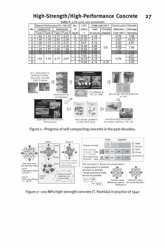
High-High-High-High-High-StrStrStrStrStrenenenenengggggth/High-Pth/High-Pth/High-Pth/High-Pth/High-Perererererffffformormormormormancancancancance Ce Ce Ce Ce Conconconconconcrrrrreteteteteteeeee 2727272727
Figure 1—Progress of self-compacting concrete in the past decades.
Figure 2—100 MPa high-strength concrete (T. Yoshida) in practice of 1940

2828282828 Okamura et al.Okamura et al.Okamura et al.Okamura et al.Okamura et al.
Figure 3—Stress-strain relations of high-strength deformed steel bars.
Figure 4—Trial designs and cost comparison.
Figure 5—Specimen details.

High-High-High-High-High-StrStrStrStrStrenenenenengggggth/High-Pth/High-Pth/High-Pth/High-Pth/High-Perererererffffformormormormormancancancancance Ce Ce Ce Ce Conconconconconcrrrrreteteteteteeeee 2929292929
Figure 6—Flexural moment-displacement relations.
Figure 7—Shear capacity ratio and ultimate rotation angle of member.
Figure 8—Damage levels and load displacement relationship.

3030303030 Okamura et al.Okamura et al.Okamura et al.Okamura et al.Okamura et al.
Figure 9—Load displacement relations for SQC specimen.
Figure 10—Detail of specimens (K2).
Figure 11—Design bond strength

High-High-High-High-High-StrStrStrStrStrenenenenengggggth/High-Pth/High-Pth/High-Pth/High-Pth/High-Perererererffffformormormormormancancancancance Ce Ce Ce Ce Conconconconconcrrrrreteteteteteeeee 3131313131
Figure 13—Coefficient of rate of carbonation and effective water-binder ratio.
Figure 14—Mean erosion depth in accelerated acid rain resistance test.
Figure 12—Results of accelerated carbonation test for SQC.
3232323232 Okamura et al.Okamura et al.Okamura et al.Okamura et al.Okamura et al.
Figure 16—Post-hardening air content and predicted cycles of freezing and thawing.
Figure 17—Scheme of performance based design.
Figure 15—Relative dynamic Young’s modulus versus freezing andthawing cycles relation.

High-High-High-High-High-StrStrStrStrStrenenenenengggggth/High-Pth/High-Pth/High-Pth/High-Pth/High-Perererererffffformormormormormancancancancance Ce Ce Ce Ce Conconconconconcrrrrreteteteteteeeee 3333333333
Figure 18—Example of substructure.
Figure 19—Design example for life cycle cost estimation.

3434343434 Okamura et al.Okamura et al.Okamura et al.Okamura et al.Okamura et al.
Figure 20—LCC estimation and sensitivity analysis.