performance analysis of a solar-powered/ …lior/documents/performanceanalysisofas… ·...
TRANSCRIPT
Solar Energy VoL 32, No. 6, pp. 753-764, 1984 0038-092X/84 $3.00 + .00 Printed in the U.S.A. Pergamon Press Ltd.
PERFORMANCE ANALYSIS OF A SOLAR-POWERED/ FUEL-ASSISTED RANKINE CYCLE WITH A NOVEL
30 hp TURBINE
KEtTU KOAI, NO/O~ LIOR and HSUAN YEll Department of Mechanical Engineering and Applied Mechanics, University of Pennsylvania
Philadelphia, PA 19104, U,S.A.
(Received 28 April 1982; accepted 9 June 1983)
Abstract--The subject of this analysis is a novel hybrid steam Rankine cycle, which was designed to drive a conventional open-compressor chiller, but is equally applicable to power generation. Steam is to be generated by the use of solar energy collected at about 100°C, and is then to be superheated to about 600°C in a fossil-fuel fired superheater. The steam is to drive a novel counter-rotating turbine, and most of its exhaust heat is regenerated. A comprehensive computer program developed to analyze the operation and performance of the basic power cycle is described. Each component was defined by a separate subroutine which computes its realistic off-design performance from basic principles. Detailed predicted performance maps of the turbine and the basic power cycle were obtained as a function of turbine speed, inlet pressure, inlet temperature, condensing temperature, steam mass flow rate, and the superheater's fuel consumption rate. Some of the major conclusions are: (1) the turbine's efficiency is quite constant, varying in the range of 68.5--76.5 per cent (75 per cent at design) for all conditions, (2) the efficiency of the basic power cycle is 18.3 per cent at design, more than double as compared to organic fluid cycles operating at similar solar input temperatures, at the expense of adding only 20 per cent non-solar energy. This, combined with the fact that actual organic Rankine cycles operate typically at temperatures above 140°C, predicts that this system would be economically superior by using less than half of the collector area and by also using less expensive collectors.
1. INTRODUCTION
1.1 Background A number of research, development and demon- stration projects have been initiated to study the applicability of low temperature (<150°C) solar power cycles to obtain cooling by the vapor com- pression method. Several reviews describe the past work[I-4], and a summary of the principal projects is shown in Table 1.
As seen in the table, most of the projects use organic fluids in the power cycle. These are desirable for such low temperature applications due to their high molecular weight and positive slope of the saturated vapor curve in the temperature-entropy plane, both attributes simplifying the design of the expander. Organic fluids have, however, also several drawbacks as compared to steam: their vapor cannot be superheated to high temperatures, the pumping power is higher, and the heat transfer coefficients are typically poorer, these in addition to possible prob- lems of instability, corrosiveness, flammability and toxicity. In particular, the practical impossibility of superheating, and to some extent the high pumping power, restrict the efficiency of the organic Rankine cycles to the range from about somewhat below or around 10 per cent at 100°C, to about 14 per cent at 150°C[2, 7].t
1"Some analyses have predicted slightly higher values of the efficiency (12-16 per cent) but they have not been attained in operation.
:~This limit is similar to that imposed in superheaters in fossil-fuel power stations.
1.2 The SSPRE Cycle Previous work[l , 15, 16] has predicted that with
the use of steam in the cycle, allowing solar heat to be applied in the boiler at 100°C, the addition of about 20 per cent of the total energy by fossil-fuel superheating of the generated steam to about 600°C,~: would essentially double the power-cycle's efficiency above that of organic-fluid Rankine cycles which operate at similar solar-collector temperatures. The proposed cycle's T-S diagram is shown in Fig. 1. Obviously, since the steam exhausting from the tur- bine is still highly superheated, its heat is recovered for preheating steam (process 6-7 delivers heat to process 3-4) and water (process 7-8 delivers heat to process 1-2). This solar-powered/fuel-assisted power cycle, dubbed SSPRE (Solar Steam Powered Rankine Engine, pronounced "espree") is shown in Fig. 2.
The underlying principle of this concept is the use of energy from two different temperature levels to arrive at (1) a better thermodynamic matching with the energy sinks in the power cycle, (2) better heat transfer characteristics, and (3) improved system economics. Lower temperature solar energy (at ,,, 100°C), which can be obtained from lower-cost collectors, supplies the heat required to evaporate water at a slightly lower temperature. Solar heat thus supplies 80 per cent of the total heat. Combustion- heat, which by necessity is generated at high tem- peratures, is used for the remainder, to superheat the steam to the top temperature of about 600°C. As compared to a plant operated by fossil-fuel alone, the better matching of the source and sink temperatures results in lower process irreversibilities. Furthermore,
753

754 K. Ko^l e t al.
8
'-d
Y
¢.
c
i VlI , , , I
!
!
0
i 0
q ,
,Y
A Q o
~|'..
$ o
|

Analysis of a solar-powered/fuel-assisted Rankine cycle
800
755
2 4 6 8 ENTROPY, kJ IkgK
Fig. 1. T-S Diagram of the SSPRE cycle.
IO 10
the high heat transfer coefficients associated with boiling water reduce the required temperature difference between the solar collector and the water, and thus also the collection temperature, improving collector efficiency. The inevitable high combustion temperature, on the other hand, provides also a high temperature difference for super heating steam. Since the gas-to-steam heat transfer process is characterized by low heat transfer coefficients, the large tem- perature differences reduce the required heat transfer
area. All the above attributes of the process also lead to significantly improved economics: lower cost col- lectors can be used and the heat exchangers and pumps are less costly.
Since the collectors constitute a major part of the solar cooling system's cost (typically more than hal0, of most significance is the fact that the SSPRE cycle requires only about half of the area of the collectors required by organic-fluid cycles of similar horse- power, and typically at a somewhat lower
I/~C"
AR COLLECTOR LOOP
FUEL EXHAUST
I~) ~°c @ 102"c JVV~, REGENER~ ~ C N ECONO.,ZER . . E R . A L I~,~ ENERGY R STORAGE
'soc @1~ •"c @ ~ .. mz*c® 0.10 BAR J 0.14 BAR
.ONDENSER
AIR OR WATER COOLING Fig. 2. Flow diagram of the SSPRE power/cooling system. A typical set of steam conditions is shown
for operation near the design point.

756 K. KOAI et al.
temperature[15-17]. The reduction in collector area must, of course, be compared to the need to supply fuel. Although at present the SSPRE cycle thus has a great economic advantage, rising fuel costs and possibly declining collector costs may change this situation. It is reasonable to predict then that at such time the high-temperature solar concentrators would become available to superheat the system eco- nomically in lieu of the fossil fuel. Here again the fundamental principle of the SSPRE concept is used to good advantage: the major portion of the heat (latent) which is required at a low temperature is supplied by a low-cost collector, and a small amount of heat (sensible, superheat) is supplied at high temperature by a source economically optimized for operation at that temperature (the concentrating collector).
Apart from the above-described applications to solar cooling, solar/fossil hybrid cycles have been considered to some extent in such areas as solar repowering of electric power plants[18], auxiliary fossil energy use in point-focusing distributed- receiver solar-thermal power systems[19], general use of low temperature heat sources[20], and with geo- thermal energy[21-23]. In the concepts described in Refs. [18, 19], fuel is used as an alternate source to solar when the latter is insufficient, but in[20-23] the fuel is proposed to be used to superheat steam generated by low temperature energy sources, such as waste heat or geothermal, in the same way as the SSPRE cycle. The geothermal source analyses also include the application of the geothermal heat to preheat the feedwater to a fuel-fired boiler, and a two-stage fuel superheat scheme. In all cases, the hybrid systems show distinct advantages over a single-source power system, as expected.
The power cycle described in this paper is intended to drive the open compressor of a commercial chiller,~" but may, of course, be also used for power generation. Supported by a contract from the U.S. Department of Energy, a power system of this type was designed to produce 30 hp (at design conditions) and drive a 25-ton (nominal) chiller. A comprehen- sive analysis of the fundamental performance aspects of the power cycle is described below. More detail is provided in[24]. An experimental facility for testing the actual turbine and system performance has been nearly completed, and data are expected to be avail- able for verifying these analytical predictions.
2. THE SYSTEM COMPONENTS AND THEIR MODELING
2.1 The scope and method o f the analysis The previous analyses of the SSPRE cycle[15, 16]
have been performed with turbine efficiency and heat exchanger and superheater effectiveness assumed to be constant. The analysis described here allows these to vary with the operating conditions. For that purpose, each of these components was modeled as a
function of its basic operational and configurational variables, and formulated as a subroutine to the overall system-analysis computer program. In this fashion, the real predicted performance of the com- ponents and of the entire system could be determined both as a function of the transient weather and cooling load forcing parameters, and of any desired variations in the configuration of the system or of its components.
To evaluate the realistic performance of the basic power cycle and of the turbine over the full range of operating conditions, it is best to isolate them at first from the influence of some of the elements which could, in principle, be varied independently. Con- sequently, the analysis was conducted here on the basic configuration shown in Fig. 3, which includes the turbine, superheater and regenerator, but without the economizer (which has a minor role in any case), the thermal storage, the solar collectors, the con- denser, the auxiliary power (fans, pumps), the chiller (load), and the pressure drops in the superheater, regenerator and piping, all of which have eventually been considered in [24], but could be varied indepen- dent of the basic power cycle, based on the techno- economical constraints of the desired system per- formance.
The modeling method and the basic power cycle's performance maps, obtained by varying one parame- ter at a time, are described below. The transient seasonal performance analysis of the entire power/cooling system has also been performed[24], but is not the subject of this paper.
2.2 The turbine Since low horsepower commercial steam turbines
which operate under the conditions of the SSPRE cycle have an efficiency typically below 50 per cent a novel 30hp radial-flow 10-stage turbine with 25 cm dia. counter-rotating rotors, which utilizes re- action blading, was designed at the University of Pennsylvania and built for operation in the system[25]. There are 5 concentric rows (i.e. stages) of turbine blades on each of the two counter-rotating rotors. The turbine is manufactured principally from type 316 stainless steel. The design predicts an
Gas exhaust
Saturated Superheater f steam in Regenerator
3 z
i v v ~ I I ~ ~ ~ I IZote t r - ~ / ~ / ~ , / % - - ~ ~ I pressure. ~7 L " " ~ ' ¢ I temperature
• I~ ~,,ueL ~P~,ro _ Ms, P3, T~ ' ~ I ~ P'ower
Steam out "n,,h,~o ~ . J output '~ ~ "= ISpeed N..~ p
lefflc - - l e f f c - ' F T . . . . de . . . . g [enc~'~" temperature L . . ~ t
6~ P,,T6 = ] exi t
pressure temperature
?Planned for a Trane Co. chiller. Fig. 3. Basic system analyzed.

Analysis of a solar-powered/fuel-assisted Rankine cycle 757
efficiency of 75% at design conditions, and excellent off-design performance (efficiency of 69-76 per cent within the full range of operating parameters).
The modeling is structured as follows:
Independent variables Inlet pressure p~ Inlet temperature T~ Exit pressure p~ Rotation speed N
Dependent variables Steam mass flow rh, Turbine efficiency r/, Power output P
The detail design and analytic derivation are reported in[25]. Briefly, the subroutine is based on the follow- ing relations.
Power output P is the product of mass flow th,, the isentropic enthalpy drop through the turbine Ah,, and the turbine efficiency ~/,, i.e.
P=6z,(Ah,)ff, (1)
Mass f low th is given by the following relation which is a more refined version of the classical Stodola's relation
r - - l \ l P' 2 2 - ~lp----~ ) ~ , - ~
xJl--(P-eY-"('-'/')(IP+v.)tan.,, (2) \~1 \v,
where A is annulus area and r is ratio of specific heats,
? ((2u)~/2) (3) v~ = (ah,) '
u is peripheral speed, r/p is polytropic efficiency, approximately equal to stage efficiency r/,,, and ~ is turbine flow absolute leaving angle.
Turbine eJficiency tl, is the product of stage efficiency, r/,,, leaving loss correction C#, reheat factor 91 and seal leakage correction C,~, i.e.
t h = TI,,91C#C,t. (4)
The variation of ~/,, with the velocity ratio v, is based on a large number of experimental data for well- designed turbines with reaction type blading[25]. The reheat factor 91 is calculated on the basis of con- ventional theory, whereas C# and C,i are calculated from the design.
steam passes through tubes which obtain heat from the furnace section of the superheater (where they are exposed to the flame and the combustion gases), and the convection section (where they are exposed to the combustion gases only). The heating through these sections can be performed either in series or in parallel. The latter was chosen for actual use in this project,? and is depicted, with its dimensions, in Fig. 4.
The heat transfer modeling was performed to provide the exit steam temperature, efficiency, and pressure drop of the superheater as a function of the steam mass flow, the fuel mass flow, the inlet tem- perature and pressure, and the superheater configura- tion, and is based on [26].
In the furnace section, the analysis shows that two equations describe the gas temperature Tg, and the total radiative/convective heat flux d r to the steam tubes
Tg = TAr(I -- 0.75 ~ ')
O ' D ' + z ' = (1 - 0.75 ~,)4
(5)
(6)
where
Q' = "reduced efficiency" -- Or G r - To (7) n," TA,~
H r is the enthalpy input rate in the feed stream (air and fuel) measured above a base temperature To (25°C),
TAr = adiabatic flame temperature = ~ ' , m:cp
thy is feed stream mass flow rate,
(8)
D ' = reduced firing density
HI - I I -k3 \
(9)
(GSO = "gas-surface total exchange area"
AT - 1 1 ' ( l O )
Ti k (11)
2.3 The superheater The steam is superheated to the desired tem-
perature in this device by the combustion of gas. The
C, is the sink fraction of total surface envelope Ar
G - A , / A T = 1 - - A , / & 02)
?A superheater was built to the University of Pennsyl- vania specifications by Trane Thermal Co., Conshohocken, Pennsylvania.
A~ is surface area of sink (steam tubes), Ar is area of total surface envelope, E, is emissivity of chamber wall, % is gas emissivity, o is the Stefan-Boltzmann constant and h is convective heat transfer coefficient

758 K. Ko~detal.
Combustion ¢1 "J ~ _ / " ( air inlet | ml l | l ~ r~
DiLution i l i l - air inLetsteo m Gas
in le t exhaust 4
Furnace Section
Length of Furnace = 1.37 m
I.D. of Furnace Shell = 0.43 m
6 coi ls
Length of coi l = 2.03 m
I.D. of tube = 1.57 cm
O.D. of tube = 1.9 cm
Material = Stainless steel (Incoloy)
Conductivity = 163.2 kJ/m-hr °C
Steam ou t le t 5
Convection Section (Counter-flow)
Length of Convection Section = 1.4 m
O.D. of Inner Shell (Furnace) = 0.51 m
I.D. of Outer Shell = 0.762 m
5 Inner co i ls
5 Outer co i ls
Length per Inner coi l = 6.935 m
Length per Outer coi l = 7.176 m
I.D. of tube = 1.57 cm
O.D. of tube = 1.9 cm
Material = Stainless steel (Incoloy)
Conductivity = 163.2 kJ/m-hr °C
Fig. 4. Superheater configuration and specifications.?
between gas and steam tubes.
T,, - (Tg + 7"1)/2 (13)
Tt is surface temperature of heat sink, and
7", , = reduced sink temperature - - - . (14)
T~r
fromeqns (5), (12),(10~ (11), (13),(9) and(14),respectively. Substituting these values into eqn (6), the final value ~ ' satisfying the energy balance is obtained by trial and error. Then the net heat flux ~r is obtained from eqn (7), and the furnace efficiency from
~F ~/" HI (16)
As a first step, the theoretical adiabatic flame temperature TAr is calculated for a constant pressure combustion process of natural gas with 20 per cent excess air, based on the heat of combustion of the reaction
CH 4 + 2.4 02 + (2.4)(3.76) N2"-'-~CO:
+ 2 H20 + 0.402 Jr 9.024 N2. (15)
T ~ was found to be 2068 K. As a second step, to calculate ~ ' , an initial guess
on the value Q ' is made. With m/given and TA~ obtained in Step 1, T v Tgt, D', and ~ are calculated
tThe superheater actually operates in vertical position: the steam outlet (on the r i o t in this figure) is at the bottom.
As a third step, the net heat flux calculated in Step 2, which is used to superheat the inlet steam, allows the determination of the exit steam enthalpy and temperature if the independent variables (the tem- perature and pressure of the steam at the inlet to the superheater, and the steam mass flow rate) are given.
As the last step, the exit gas temperature Tcorn b c a n
be obtained by
r ~ -- r~ - ~ r~,. (17)
The convection section of the superheater is as- sumed to be essentially a single-pass counterflow heat exchanger, with steam flowing in the tubes. Using conventional correlations for the external and inter- nal convective heat transfer coefficients, the effectiveness, heat transfer rate ~ r and exit tem-
Analysis of a solar-powered/fuel-assisted Rankine cycle
perature of the steam and the combustion gas are calculated. The overall superheater efficiency r/~ is determined from
Or+Or (18) ??,up = /If
2.4 The regenerator This is a counterflow/cross-flow steam-to-steam
shell-and-tube heat exchanger with the hotter steam flowing inside the tubes. The dimensions and configuration of the regenerator purchased for this project are shown in Table 2.
The regenerator's effectiveness, total heat transfer rate, and outlet temperatures and internal pressure drops of the two steam streams are calculated as a function of their mass flows and inlet states, and of the regenerator's configuration. The conventional procedure outlined in[27], and which involves the computation of internal, external, and overall heat transfer coefficients, as well as pressure drops, is used in a straightforward way.
The predicted performance of both the superheater and the regenerator was found to be within a couple of percent from that which the manufacturers of these units quoted.
3. PERWORMANCE OF THE BASIC SSPRE CYCLE
3.1 Objectives In the following, the influence of the rotating speed
ratio (N/N*), turbine inlet temperature T. turbine inlet pressure p~ (determined by solar-input boiler temperature), and turbine exhaust pressure (deter- mined by the imposed condensing temperature), on turbine efficiency, steam mass flow, power output, superheater fuel consumption, and thermal efficiency of the Rankine cycle were determined in detail, for
759
the system configuration described in Figs. 3 and 4 and Table 2, using the simulation program described in Section 2 above.
The thermophysical properties of the fluids used are described as separate subroutines in the program. The superheater and regenerator subroutines were each run separately, and successfully validated against results computed by the manufacturers of these units. The superheater efficiency was ,,~ 0.77 and the effiectiveness of the generator ~ 0.6-0.7 in the investigated range.
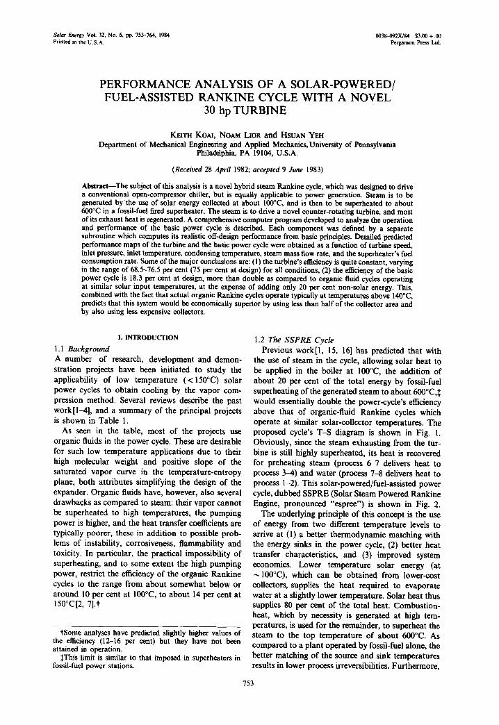
As shown in Fig. 5, the turbine efficiency is well maintained throughout the range of rotating speeds: r/, = 68.5-76.5 per cent at design) for 0.65 < N/N* ~ 1.1.
The turbine efficiency is the product of the stage efficiency, the reheat factor, and the leaving loss correction. As shown in Section 2.2, stage efficiency (t/,,) depends only on the isentropic velocity ratio (v,), and reaches a maximum (the design t/~) when v, = v,*. Since v, is essentially the ratio of peripheral velocity to the flow velocity relative to the blade, physically when v, = v*, all flow angles are the same as design, thus the stage efficiency is the highest possible.
When p~ or T~ increases, the isentropic enthalpy drop (zth,) increases. It requires a higher speed N to reach the same value of v, as the design value, v*. Hence, the peak stage efficiency occurs at a higher speed. The peak turbine efficiency, however, is higher for higher p~ because the reheat factor increases with Pi-
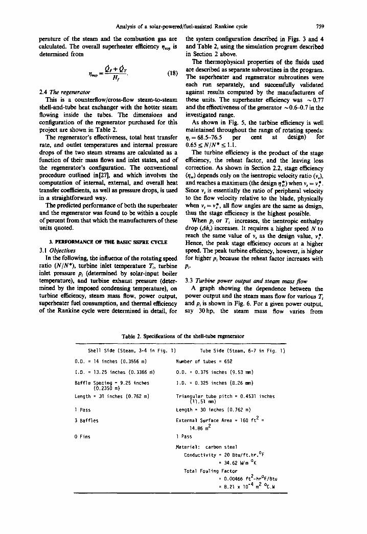
3.3 Turbine power output and steam mass flow A graph showing the dependence between the
power output and the steam mass flow for various T~ and p~ is shown in Fig. 6. For a given power output, say 30hp, the steam mass flow varies from
Table 2. Specifications of the shell-tube regenerator
Shell Side (Steam, 3-4 in Fig. I)
O.D. = 14 inches (0.3556 m)
I.D. = 13.25 inches (0.3366 m)
Baff le Spacing = 9.25 inches (0.2350 m)
Length = 30 inches (0.762 m)
l Pass
3 Baffles
0 Fins
Tube Side (Steam, 6-7 in Fig. I )
Number of tubes = 652
O.D. = 0.375 inches (9.53 ram)
I.D. = 0.325 inches (8.26 ram)
Triangular tube pitch = 0.4531 inches (11.51 ram)
Length = 30 inches (0.762 m)
External Surface Area = 160 f t 2 =
14.86 m 2
I Pass
Mater ia l : carbon steel
Conductivity = 20 Btu / f t .h r . °F
= 34.62 W/m OK
Total Fouling Factor
= 0.00466 ft2-hr°F/Btu
= 8.21 x lO "4 m 2 °C.W
760 K. Ko~d et al.
160.2kg/hr at T~=600°C and pi= 1.01 bar to 251 kg/hr at T~ = 260°C and p~ = 1.3 bar. The slope (dP/dth,)r, at constant temperature T~ ranges from i hp/4.08 kg/hr to 1 hp/8.04 kg/hr at T~ equal to 600 and 200°C, respectively. The slope (dP/d~h,)p, at constant pressure p~ ranges approximately from 1 hp/3.80 kg/hr at p~ = 1.3 bar to 1 hp/5.65 kg/hr at Pi = 0.5 bar.
| "[i I ' C ) O E S I O N ooIi ('Cl
\ X,, i °"K// \,oX; F \ x
°- F o,,! \
N/N", SPEED/DESIGN SPEED
Fig. 5. Turbine efficiency vs the speed ratio, p~ = 1.0133 bar, TS=46°C.
50
/,5
Z,0
35
30
o 25
.-2 0- I w e,.. 20
15
10
0 60
l I I I I I
"P,, oe.>
: : ' / , / , / , ,+ .o, ;/1,/,,/,,,,
~,~ •
I I I t I I 90 120 150 180 210 2"0 2 7 0
STEAM MASS FLOW r~, lkg/hr)
Fig. 6. Turbine power vs steam mass flow rate. 15,300 RPM, Ts.=46°C.
The analysis has also shown that the power output increases with the turbine inlet temperature, being roughly proportional to ~ (T: absolute inlet tem- perature). The slope (dP/dT) ranges from 1 hp/26.8°C at p~ = 1.3 bar to 1 hp/122°C at p~ = 0.4 bar. For the design inlet pressure (1.0133 bar), the slope is 1 hp/37.4°C.
A linear dependence exists also between the power output and inlet pressure. The rate of increase (dP/dp~) ranges from 4 hp/0.1 bar at Tt = 600°C to 3 hp/0.1 bar at T~ = 200°C.
Further results on the turbine's performance are presented in[25].
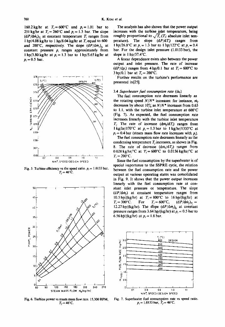
3.4 Superheater fuel consumption rate (fiaf) The fuel consumption rate decreases linearly as
the rotating speed N/N* increases: for instance, th/ decreases by about 10% as N/N* increases from 0.65 to 1.1, with the turbine inlet temperature at 600°C (Fig. 7). As expected, the fuel consumption rate increases linearly with the turbine inlet temperature T, The rate of increase (dthy/dT 3 ranges from I kg/hr/170°C at p~ = 1.3 bar to 1 kg/hr/1333°C at p~ = 0.4 bar (steam mass flow rate increases with p~).
The fuel consumption rate decreases linearly as the condensing temperature T/increases, as shown in Fig. 8. The rate of decrease (d,'h:/dTi) ranges from 0.028 kg/hr/°C at T~= 600°C to 0.0156kg/hr/°C at T, = 2oooc.
Since the fuel consumption by the superheater is of special importance to the SSPRE cycle, the relation between the fuel consumption rate and the power output at various operating states was consolidated in Fig. 9. It shows that the power output increases linearly with the fuel consumption rate at con- stant inlet pressure or temperature. The slope (dP/dth:) at constant temperature ranges from 10.5 hp/(kg/hr) at T~ = 800°C to 16 lip/(kg/hr) at T~ = 300°C. F o r T~ = 600°C, ( d P / d r h f ) r ~ = 12.27hp/(kg/hr). The slope (dP/drhy)p, at constant pressure ranges from 3.64 hp/(kg/hr) at p~ = 0.5 bar to 6.56 hlb/(kg/hr) at p~ = 1.8 bar.
-c~ 3 0 ~ " ~
~ - ~ 2.s ~ . ~
i 2o L
J 15 oJ
". tO
• E 05
I ' I ' i ' I i [
Ti I'C) - 600 DESIGN
550 500 1.50 400 350 300 2 5 O
2 0 O
07 0 8 09 1.0 1.1
N/N II, SPEED/DESIGN S P E E D
Fig. 7. Superheater fuel consumption rate vs speed ratio. p~ = 1.0133 bar, Tf= 46°C.

Analysis of a solar-powered/fuel-assisted Rankine cycle 761
3.5
~3.0
I 2.5
~: 20
1.5
LL0
.E =" 0.5
I I I
Ti (°C)
200
0 l , I , l , I , 36 40 "-/. 48 52
CONDENSING TEMPERATURE I f ('C)
Fig. 8. Superheater fuel consumption rate vs condensing temperature. 15,300 RPM.
superheater may seem to be desirable, but cannot be considered independently, since it is closely related to the other components in the system. Especially note- worthy is its effect on the size, quality and thus the cost of the solar collector field which provides the major part of the energy to the cycle.
Figure 10 shows the turbine power output as a function of the ratio of fuel energy input O,~p and the steam enthalpy input rh/~. from the storage, at various turbine inlet T~ and p~. The power output increases with the ratio (Q~,/thA.,) almost linearly at constant inlet pressure while the turbine inlet tem- perature increases as expected.
3.4 Thermal efficiency of the Rankine cycle 01~c): The thermal efficiency of the basic Rankine cycle
can be calculated from
h 3 - h 6
~Rc = (h5 - h4) + (h3 - h2) + (hi - hi0)" (19)
I i i I I q
70 ,~l.O
q~t" 'I S 6o ~~ "i~ "~'" . . . , / 50 ~ : " / " " '% ' f - - ,~L3 Pilso,)
.-~/Z-' . .
~o ~o " "/:f.'f.'_/./7
• o o 1.0
30 "~. - o.g 0-
20 ~ 07
0 6 10 0.5 F 031 1 t I
0 1 2 3 4 5 5 7
t~FUEL , FUEL FLOW RATE {kg/hr)
Fig. 9. Power vs fuel consumption. 15,300 RPM, TI= 46°C. Regenerator inlet steam is at T 9.
Figure 9 also shows the turbine inlet pressure range which can supply a required power demand. For instance, if the power demand is 30 hp, the allowable range of steam inlet pressure is 0.92 < p~ < 1.25 bar with inlet temperature 800 > TI. > 208°C, and fuel consumption rate 3 . 4 > m r > l.Skg/hr. The upper bound of this pressure range corresponds to the lowest allowable limit of turbine inlet temperature to keep the turbine dry; whereas the lower bound of this pressure range corresponds to the material thermal limit of the turbine inlet temperature. Within this pressure range, the required fuel consumption and steam superheat temperature for the same power output decrease with increasing p , since the enthalpy drop between the inlet and exit steam increases with p~ for the same p,.
The reduction of the fuel consumption by the
The state points are defined in Figs. 1 and 2. The inlet steam to the regenerator from the storage is assumed to be saturated. The enthalpy hi0 is for saturated water at the pressure p,, and h, is for saturated water at the pressure Pl. The enthalpy h5 is specified by the inlet state to the turbine, and h6 is determined by the turbine calculation, h4 is determined by the regen- erator calculation.
Figure 11, showing J/Rc as function of the turbine inlet temperature T, and rotating speed (N/N*), indicates that all curves go through a maximum. The
45
40
35
30
tw uJ
25 O 0_
~ 20 g.
15
10
0-- 0.05 0.10 0.15 0.20 0.25 0.30
Qsupl msh in , FUEL ENERGY/
STEAM E N T H A L P Y INPUT FROM STORAGE
Fig. I0. Power vs fuel cnergy/"solar energy" fraction. 15,300 RPM, Tr= 46°C.

762 K. Ko~d et al.
0.19
0.18
~ 0 . 1 7 F"
"J 0.16
co E 0.15
w
0.I/.
z w 0.13
~ 0 1 2
0.11
I i , i , I T i ( ~ S I G N
550
500
z.50
/ zOO
350
3OO
250 ......
200
0.10 I J I ' I I I , J 0.7 0 8 0.9 10 1.1
NIN*, S P E E D / D E S I G N S P E E D
Fig. l l . SSPRE cycle efficiency vs speed ratio. p~ -- 1.0133 bar, Tf= 46°C.
maximal points of ~/,c move to lower N/N* values as the inlet temperature T~ decreases (with Pt and T/kept constant). The maximum point occurs at design speed for T~ = 600°C, and at N/N* = 0.75 for T~ = 200°C. This corresponds to the similar trend of the turbine efficiency in Fig. 5.
V/Re increases almost linearly with the inlet tem- perature T~ at constant inlet pressure. The rate of increase (dtlRc/dT) ranges from 1.65%/100°C~ " at pj = 1.3 bar to 1.5 per cent/100°C at p~ = 0.6 bar. t/s c increases with the inlet pressure at constant tem- perature since the enthalpy drop (hs--h6) and thus the power output increase.
v/R c decreases with the condensing temperature T/ (Fig. 12). The rate of decrease (dthc/dT/) ranges from 0.29 per cent/°C with T~ -- 600°C to 0.244 per cent/°C with 7",. = 200°C.
Figure 13 shows that the thermal efficiency of the Rankine Cycle 01Re) increases with the fuel energy ratio ((~,,p/m,h~n) at constant turbine inlet tem- perature or inlet pressure. At the design pressure pi = 1.0133 bar, r/x c is 18.2 per cent at 600°C, and 8.8 per cent at 100°C (extrapolated). It can thus be seen again that the addition of 20 per cent (0.25/1.25) non-solar energy out of the total energy input dou- bles the cycle's thermal efficiency.
4. CONCLUSIONS eI t is predicted from the design and analysis that
the novel low-horsepower steam turbine developed for the solar-powered/fuel-assisted cycle has an efficiency of 75 per cent at design conditions, and would maintain it between about 69 and 76 per cent
tHere 1.65 per cent refers to the absolute increase for rlec. At design r/R c is 18.2 per cent. In other words, the relative increase is 9 per cent. This definition applies also to the other slopes of T/Re until the end of the paper.
over the full range of widely different operating conditions. This is an improvement of at least 50 per cent over existing commercial steam turbines oper- ating at similar conditions.
eThe study of the basic cycle shows that the thermal efficiency of the proposed Rankine power cycle is 18.3 per cent at the design thermodynamic
0.20
0.19
0.18
>.- 0.17
llJ G 0.16 ,7 m 0.15 w _J u )- 0.14
x 0.13 Z
0.12
0.11
0.10 I = I I I , I ¢ I 36 40 td. /.8 52
CONDENSING TEMPERATURE If ('C)
Fig. 12. SSPRE cycle efficiency vs condensing temperature. pj = 1.0133 bar, 15,300 RPM.
0.22 , i
~@ 600 0.20 ~ , / . q l .3~
41 o.16 @---
w D .
0.16 7
o.1~ ",,,/o.'. P~ o ~ , (Bar) - /
o.12 ,)o/-
' [ ~ 0.10
0"08 t
0.061 I t t t " 0.05 0.10 0.16 0.20 0.25 0.30
Osup lmsh in , FUEL ENERGY/ STEAM ENTHALPY INPUT FROM STORAGE
Fig. 13. SSPRE cycle efficiency vs fuel energy/"solar energy" fraction. 15,300 RPM, T/= 46°C.

Analysis of a solar-powered/fuel-assisted Rankine cycle 763
conditions (turbine inlet at 1.01 bar, 600°C; steam condensation at 46°C) and turbine design speed (15300rpm). In comparison with the conventional solar-powered Rankine cycle operating at the satur- ation temperature corresponding to the above pres- sure (100°C), this hybrid cycle offers a much higher efficiency than that of organic fluid Rankine cycles (which is < 10 per cent), or the saturated steam Rankine cycle (8.8 per cent). By superheating the steam to the design level of this novel power cycle for solar power and cooling, the cycle's thermal efficiency is more than doubled at the expense of adding only 20 per cent non-solar energy out of the total energy used.
sPredicted performance maps of the turbine and the cycle over a full range of operating parameters have been presented.
Acknowledgement--The University of Pennsylvania gradu- ate students Stuart Bassler and Albert Leung have assisted in the development of the computer program. Major con- tributions to the turbine analysis were made by Profs. R. P. Kroon and C. A. Meyer. This project was supported by the USDOE Office of Conservation and Solar Applications, Solar R & D Branch.
Greek
NOMENCLATURE A turbine flow annulus area % specific heat at constant pressure, J / k g - C
Cu turbine leaving loss correction Ca turbine seal leakage correction
h specific enthalpy of steam, J/kg; film co¢fficienf of heat transfer, kJ/m 2 - hr C
h~ coefficient of convective heat transfer, IO/m 2 - hr C
H/ fuel energy input rate or the fuel enthalpy input rate, kJ/hr
m/ fuel mass flow rate, kg/hr m, steam mass flow rate, kg/hr N turbine rotation speed, rpm p pressure, bar
Ap pressure drop, bar P turbine power output, hp
heat transfer rate, kJ/hr R universal gas constant
reheat factor T temperature, °C T/ steam condensing temperature, C u turbine peripheral speed
symbols ~ turbine flow absolute leaving angle E~ emissivity of superheater's furnace chamber wall % emissivity of combustion gas ~/, furnace efficiency r/p polytropic expansion efficiency
r/Re Rankine cycle thermal efficiency r/s , stage efficiency of turbine
r/~ superheater efficiency r/, turbine efficiency K epiC v v, isentropic velocity ratio of turbine stages o Stefan-Boltzmann constant, 5.668 x 10 -8
W/m 2 K 4
Subscripts AF adiabatic flame
comb exit combustion gas e turbine exit
F furnace g combustion gas i turbine inlet s steam
sup superheater T superheater convection section
1,2... 10 thermodynamic state points
Superscripts * design conditions
REFERENCES i . N . Lior, Methods for improving the energy per-
formance of heat pumps. Presented at the 9th Inter- society Energy Conversion Engng Conf., San Francisco, California, 1974. Also University of Pennsylvania MEAM Report No. 74--4 (1974).
2. H. M. Curran, Assessment of solar-powered cooling of buildings, Final Report HIT-600, Hittman Associates, NTIS:COO/2522-1. (1975).
3. R. Merriam, Solar air conditioning study. NTIS Docu- ment No. AD/A-043*951 (1977).
4. N. Lior, H. Yeh and I. Zinnes, Solar cooling via vapor compression cycles. Proc. 1980 Ann. Meet., 3.1, Inter- national Solar Energy Society, American Section, Phoe- nix, Arizona, 210 (1980).
5. D. Prigmore and R. Barber, Cooling with the Sun's Heat, design consideration and test data for a Rankine- cycle prototype. Solar Energy 17, 185 (1975).
6. R. E. Barber, Current costs of solar powered organic Rankine cycle engines. Solar Energy 20, 1 (1978).
7. R. Barber, Solar Rankine air-conditioning systems. ASHRAE Trans. 2, 760 (1979).
8. R. A. English, Development of a high temperature solar powered water chiller. Report SAN-1590-1, U.S. Dept. of Energy, (1978).
9. S. J. Hynek, A. C. Harvey, R. L. Demler, D. H. Walker and H. H. Fuller Design and development of a recip- rocating low temperature Freon expander, Proc. 16th IECEC, 1, Paper No. 819613, 1387 (1981).
10. J. Rousseau and J. Noe, Solar-powered Rankine-cycle heat pump system. Proc. IECEC, 1163 (1976).
1 I. S. E. Eckard, Test results for a Rankine engine powered vapor compression air-conditioner for 360°K heat source. Proc. IECEC, 1169 (1976).
12. J. C. Graf, Rankine cycle solar driven heat pump development. DOE Review Meeting, NTIS Report CONF-8OOMO, pp. 1-11 (1980).
13. F. R. Biancardi, Design and operation of a solar- powered turbocompressor air-conditioning and heating system. Proc. IECEC, 186 (1975).
14. F. R. Biancardi and G. Melikian, Analysis and design of an 18-ton solar powered heating and cooling system. Proc. IECEC 1459 (1978).
15. N. Lior, Solar energy and the steam Rankine cycle for driving and assisting heat pumps in heating and cooling modes. Energy Cony. 16, 111 (1977).
16. H. M. Curran and M. Miller, Evaluation of solar- assisted Rankine cycle concept for the cooling of build- ings, Proc. lOth IECEC 1391 (1975).
17. H. M. Curran, Solar/fossil Rankine cooling. Proc. 16th 1ECEC 2, 1662 (1981).
18. L. E. Van Bibber and W. G. Parker, An evaluation of alternate system configurations for solar repowering electric power plants. Proc. 16th IECEC 2, 1782 (1981).
19. R. E. Irwin, D. A. Rodriguez and R. L. Pons, Opti- mization of a hybrid solar thermal power system. ASME Paper No. 81-WA/SOL-28 (1981).
20. C. G. Martin and P. F. Swenson for Energy Technology Inc., Method of converting low grade heat energy to useful mechanical power. U.S. Patent No. 3, 950, 949, (1976).

764 K. KOAI et al.
21. R. DiPippo, H. E. Khalifa, R. J. Correia and J. Kestin, Fossil superheating in geothermal steam power plants. Proc. 13th IECEC 2, 1095 (1978).
22. J. Kestin, R. DiPippo and H. E. Khalifa, Hybrid geothermal-fossil power plants. Mech. Engng 100, 12, 28 (1978).
23. R. DiPippo, J. Kestin, E. M. Avelar and H. E. Khalifa, Compound hybrid geothermal-fossil power plants: Thermodynamic analyses and site-specific applications. ASME Paper No. 80-Pet-83 (1980).
24. N. Lior, K. Koai and H. Yeh, Analysis of the solar- powered/fuel-assisted Rankine cycle cooling system. Report SAN/20110-5, Submitted to the USDOE, (1981).
25. R.P. Kroon, C. A. Meyer, N. Lior and H. Yell, Design
of a 30 HP solar steam powered turbine. Topical Report DOE/ET/20110-3 (DE 8200 7236) to the USDOE (1981).
26. H. C. Hottel and A. F. Sarofim, Radiative Transfer, pp. 459 to 470, McGraw-Hill, New York (1967).
27. D. Q. Kern, Process Heat Transfer, McGraw-Hill, New York (1960).
28. R. L. Webb, Air-side heat transfer in finned tube heat exchangers. Heat Transfer Engng 1, 33 (1980).
29. W. M. Rohsenow and J. Hartnett, Handbook of Heat Transfer pp. 12-19, McGraw-Hill, New York (1973).
30. N. Lior, I. Cohen and Y. Tartakovski, Analytical and Design Considerations for an Integral Thermal Storage~Flashed Steam Generator. University of Penn- sylvania SSPRE Report. To be published.