perception owners’ notes - san juan sailing
TRANSCRIPT

Perception Owner’s Notes September 2021
1
PERCEPTION Owners’ Notes
Lagoon 42
Welcome aboard Perception! We think the stars aligned to bring Perception into our lives in early 2021. After a year of quarantine, she was just the right prescription to get over 2020. Her name, Perception, is a nod to Jim’s tech start-up company that gives us the ability to test the meaning of “working remotely.” We are excited to share her with you and yours through San Juan Sailing. Since our home is in Boise, Idaho, we lived aboard the vessel for two months getting her ready to join the San Juan Sailing Fleet. During this time, we tried to provision the boat with everything we would need to live comfortably aboard, and hope you find her well-appointed during your stay as well. The sleek, modern, design of this upgraded Premium Owners version of the 2019 Lagoon 42 includes:
• 3 cabin layout with king size owner’s berth and private en suite, king size berth and double v-berth. All berths have custom premium upgraded mattresses that provide comfortable sleeping arrangements for up to 6 people. The owner’s cabin offers additional storage to keep your personal effects and provisions organized and accessible throughout your stay onboard.
• Thoughtfully planned galley and Saloon offers generous food storage and refrigeration/freezing capacity. You won’t be needing to pile your provisions up in front of the windows while aboard this vessel!

Perception Owner’s Notes September 2021
2
• Panoramic windows that provide lots of natural light and 360° views.
• Cockpit and main Saloon that flow together like an open-air apartment. The Cockpit can be fully enclosed from the elements and still offer a panoramic view or drop the blackout shades as well to keep cool.
• The elevated helm station was designed for operation by a small crew, optimizing circulation and open, direct access to both the deck and the Cockpit. It is protected by a composite bimini and sliding cover with direct access to the coach roof and boom. Self-tacking jib allows for efficient, single-handed tacking.
We kindly ask that you treat her as if she were your own and please absolutely no smoking or animals allowed while onboard. Our hope is that you enjoy Perception as much as we do. If you can think of anything that would make her more enjoyable, please let us know through San Juan Sailing. Also, if questions arise during your charter, please don’t hesitate to call us at 208-867-1666. Text if you don’t get answer on the phone and we will get right back to you. Thank you for being our guests! Warm regards, Melinda and Jim Hall

Perception Owner’s Notes September 2021
3
Index
Anchors and Windlass .................................................... 7 Barbecue ......................................................................... 9 Batteries/Charging/Inverter ........................................... 9 Berths and Bedding ...................................................... 12 Bilge Pumps .................................................................. 12 Cockpit and Helm Enclosure ......................................... 13 Dinghy/Outboard/Davit ................................................ 13 Electrical ....................................................................... 16 Electronics/Instruments ............................................... 17 Emergency/Safety Equipment ........................................ 6 Engines ......................................................................... 21 Entertainment Systems ................................................ 23 Fuel ............................................................................... 24
Heads and Holding Tanks ............................................. 24 Heaters (Cabin Hydronic Heater) ................................. 27 Lighting ........................................................................ 28 Nuances ......................................................................... 5 Refrigeration and Freezer ............................................ 29 Sails and Rigging ........................................................... 29 Showers and Sumps ..................................................... 31 Spares and Tools .......................................................... 32 Specifications and Vessel Information ........................... 4 Storage ......................................................................... 32 Stove/Oven, Microwave, Keurig Coffeemaker ............. 32 Water ........................................................................... 34
Perception Owner’s Notes September 2021
4
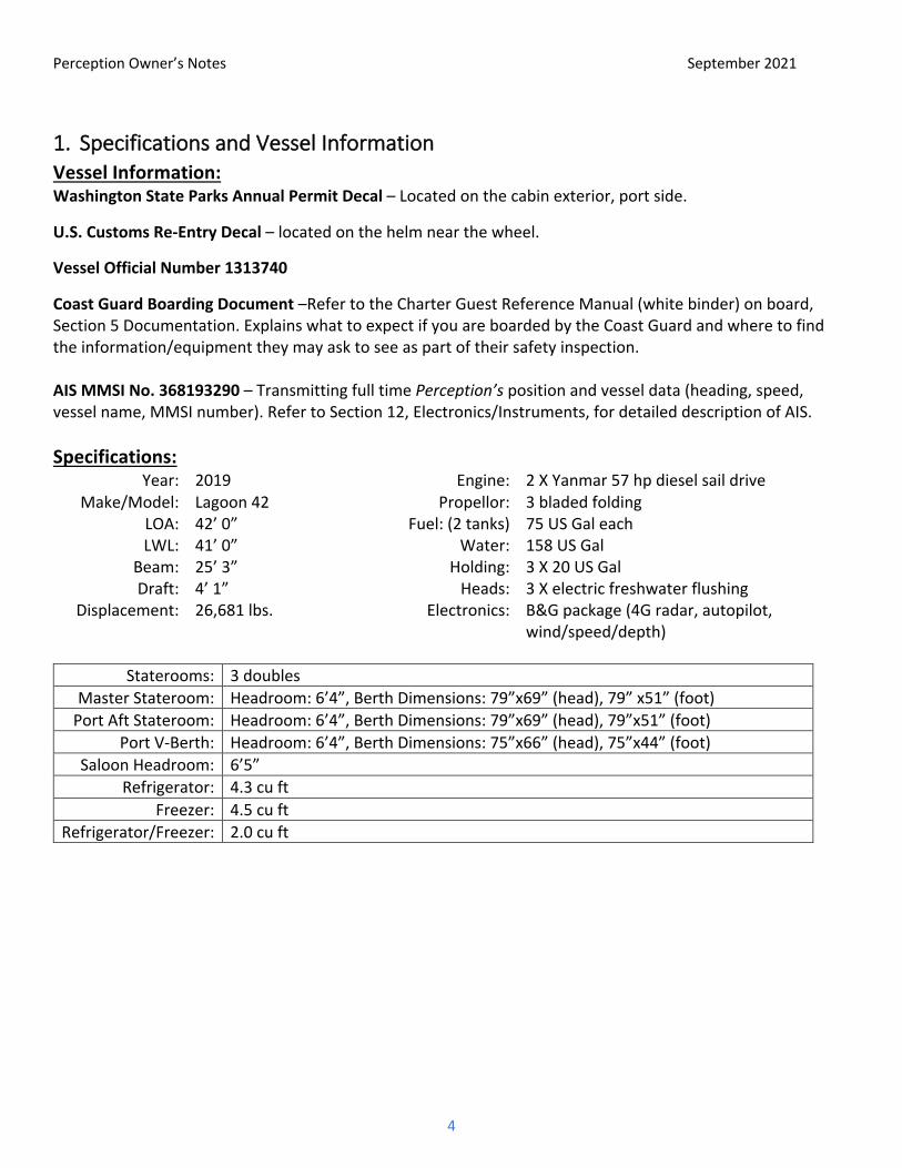
1. Specifications and Vessel Information Vessel Information: Washington State Parks Annual Permit Decal – Located on the cabin exterior, port side.
U.S. Customs Re-Entry Decal – located on the helm near the wheel.
Vessel Official Number 1313740
Coast Guard Boarding Document –Refer to the Charter Guest Reference Manual (white binder) on board, Section 5 Documentation. Explains what to expect if you are boarded by the Coast Guard and where to find the information/equipment they may ask to see as part of their safety inspection. AIS MMSI No. 368193290 – Transmitting full time Perception’s position and vessel data (heading, speed, vessel name, MMSI number). Refer to Section 12, Electronics/Instruments, for detailed description of AIS. Specifications:
Year: 2019 Engine: 2 X Yanmar 57 hp diesel sail drive Make/Model: Lagoon 42 Propellor: 3 bladed folding
LOA: 42’ 0” Fuel: (2 tanks) 75 US Gal each LWL: 41’ 0” Water: 158 US Gal
Beam: 25’ 3” Holding: 3 X 20 US Gal Draft: 4’ 1” Heads: 3 X electric freshwater flushing
Displacement: 26,681 lbs. Electronics: B&G package (4G radar, autopilot, wind/speed/depth)
Staterooms: 3 doubles
Master Stateroom: Headroom: 6’4”, Berth Dimensions: 79”x69” (head), 79” x51” (foot) Port Aft Stateroom: Headroom: 6’4”, Berth Dimensions: 79”x69” (head), 79”x51” (foot)
Port V-Berth: Headroom: 6’4”, Berth Dimensions: 75”x66” (head), 75”x44” (foot) Saloon Headroom: 6’5”
Refrigerator: 4.3 cu ft Freezer: 4.5 cu ft
Refrigerator/Freezer: 2.0 cu ft

Perception Owner’s Notes September 2021
5
2. Nuances There are a few things about Perception that are not ‘typical’. These are the things that may require special attention or where it may be best to deviate from customary operating procedures. We have listed some here because we believe they will help you plan your charter.
Hot Water: CAUTION: Water heated by the engines can be scalding hot. Be very careful to adjust temperature appropriately. For best results, use half pressure and avoid a scalding/freezing cyclical shower. PLEASE ASSIST CHILDREN!
Galley Sink Sea water spigot: Turn the knob on the spigot and depress the button located at the top right-hand corner of the open shelf cabinet under the stovetop. Galley sink drainboard does not have enough slope to properly drain and water can accumulate in the corner towards the sliding glass door. We remedy this by rolling a towel lengthwise and laying it on the rim above the sink. Hydronic Heater: After shutting down the engines you may notice a pump running in the port engine compartment. This is normal cycling of the hydronic heating fluid. The pump will run as long as cabin heaters are running and the fluid is warm. Turn cabin/saloon thermostats to low to stop the hydronic fluid pump. Mainsail Halyard: The mainsail halyard block where it attaches to the head of the sail does not swivel. Be sure to take the twist out of the halyard lines before attaching the halyard block to the head of the sail. Starboard Cabin Hatch: The entire starboard hull may be closed for privacy by sliding a section of the wall closed over the bottom of the companionway. Note that the windlass breaker is in a cabinet behind this sliding section. Engine Stop Buttons: There is a red emergency stop button on the top of each engine that is prone to getting bumped during engine checks. If an engine won’t start, check that its red button is set to “RUN”. Folding Propellers: After shutting down the engines we shift into reverse for a second to stop counter-rotation, allow blades to feather, then shift back to neutral. Holding tank monitors: Please do not hold down the buttons on the tank monitors, as this will put them into calibration mode, rendering them inaccurate for future measurements. The buttons on the tank monitors are quite sensitive and will actuate if leaned against. Rafting: Do not raft Perception with other boats. See the section on anchoring for more information.

Perception Owner’s Notes September 2021
6
3. Emergency/Safety Equipment Emergency/Safety Equipment Locations: You are not likely to need these but must know their location.
• Bilge Pumps (manual): Pump handles insert into the pumps on the inboard side of each hull above the aft stairs at the back of the Cockpit. Pump handles are stored in clips on the underside of the port Cockpit locker lid. Note: if water rises above floorboards, can use shower sump pumps also in emergency.
• Carbon Monoxide Detectors: At the top of the companionways into the starboard and port hulls. • Cockpit Cushions: In case of COB, throw anything that floats, quickly. • Emergency Tiller: T-shaped pipe in port Cockpit locker. • Fire Blanket: Saloon Open Shelf, starboard side, bottom cubby • Fire Extinguishers (5):
o Galley Open Shelf, Saloon, mounted by door starboard side o Port hull, aft cabin mounted on wall o Port Hull forward cabin, mounted on wall o Starboard hull, mounted at foot of stairs o Cockpit locker, aft
• First Aid Kit: Saloon Open Shelf, starboard side, bottom cubby • Flares (Pyrotechnic with gun): Green mesh bag in Cockpit seat locker • Flashlights: Saloon Open Shelf, starboard side, bottom cubby and Nav Table • Horn, handheld: Green mesh bag in Cockpit seat locker • Horseshoe Buoy: Port stern pulpit. • Rigid Life Buoy with Floating Light: Starboard stern pulpit. • PFDs – Inflatables (8): 2 each located in the stateroom hanging lockers, 2 spares in Cockpit seat island
with 4 additional non-inflatable vests. NSO: please check for “green” visible at bottom of clear canister before each cruise. That verifies the auto-inflate function when immersed. We wear these at all times when working the deck or the Cockpit while underway.
• PFD: – Throwable Type IV: In the Cockpit above the setee. • Radar Reflector (tube style): Port shroud above first spreader. • Spares: Port Forepeak • Tapered Plugs, Red and Orange StaPlugs: Green mesh bag in Cockpit seat locker • Tools. West Marine Shipyard 175 pc toolkit and supplemental tool bags in Saloon under port-side
settee seat next to port hull companionway. • VHF Radios: VHF base unit at Nav Station & handheld at helm. • Through-hull Valves/Fittings: A schematic showing through hull locations is in the Charter Guest
Reference Manual aboard.

Perception Owner’s Notes September 2021
7
4. Anchors and Windlass Highlights
• Rocna primary with 240' chain and 60’ nylon rode, chain has one yellow poly line interwoven at each 25’ and two lines at 100' and 200’
• Windlass clutch release/tighten wrench is located in a holder inside the starboard deck locker. • Windlass breaker located in cabinet on the inboard side of the starboard cabin behind the sliding door • Delta secondary with 30’ chain and 150’ nylon rode in port deck locker • Snubber should always be attached to chain when anchor is up • Bridle should always be attached to chain when anchor is down • Chain can build into mountain under windlass in port deck locker when retrieving • 375' polypropylene stern tie line on spool at stern • Windlass control is located in the forward center starboard locker • Anchor windlass may trip breaker when retrieving anchor from depths > 40’, or with repeated
retrievals without a cool-down period
Figure 1: Windlass and winch breakers
Figure 2: Chain length marking
Details
• Primary Anchor – Rocna 33kg mounted on the bow, with 240’ 3/8” chain, 2’ yellow poly line at each 25’ and two poly lines at 100’ and 200’.
• Bridle - Permanently attached to each bow and clipped to anchor. • Snubber – Attached to central cleat on the chain runway • Secondary Anchor – Delta secondary anchor and rode stowed in the forward center port locker. • Windlass Breaker - The windlass breaker is in a cabinet behind the sliding door to the starboard cabin
on the inboard side of the hull. The sliding door must be closed to access this cabinet. To Deploy Anchor:
1) We check tide tables to determine current water level and amount of drop while anchored. 2) Weather (ch 4 or 7, “Northern Inland Waters”) helps select an anchorage. 3) The windlass breaker is in a cabinet on the inboard side of the starboard cabin behind the sliding door. 4) Normal for the San Juan Islands is a 4 to 1 scope, bow to bottom (add 5 feet to depth sounder reading:
5’ freeboard and 1’ for transducer below waterline). In San Juans, anchorages are often about 25’ bow to bottom, so we often deploy about 100’ chain.
5) Remove the snubber from the chain. 6) With one fluid motion we lower to approximately the number of feet on the depth sounder so the
anchor is near the bottom by depressing the down switch. 7) A signal to the helmsman prompts reverse at idle speed while deploying rode to the desired scope.

Perception Owner’s Notes September 2021
8
8) We then allow the anchor to set and to stop the boat while it continues in reverse, idle speed. We then line up objects on shore to determine if we are holding, staying in reverse at idle for about one minute.
9) Finally, we hook up the bridle at the bow roller and then ease the windlass until the bridle is taking the strain. If stronger winds are forecast, we test with RPM at half the projected windspeed (1,000 rpm for winds to 20 knots; 1,500 rpm for 30 knots, etc), after setting bridle. (We check movement shoreside, not the significant prop current going by the chain.)
10) In storm conditions (or storm forecast), you can increase scope if there is adequate room to leeward. 11) The secondary anchor is available for additional holding power if a storm is anticipated, but best if set
before the storm hits. 12) If anchored in a small cove, you may wish to deploy a line ashore. 375’ floating polypropylene on a reel
resides on the stern transom. Deploy the line with the dinghy while the spool unwinds. If sufficient length, bring the line around a secure shore object and back to the boat to a transom cleat for ease of retrieval. The line should be tied to one or both stern outboard cleats on the corners of the boat. Do not rely on the reel to hold the boat.
To retrieve the anchor:
1) Start at least one engine, given that the windlass draws from the 12V domestic battery. 2) Depress “up” switch, always assuring the chain is vertical during retrieval—this avoids either towing
the boat or dragging the chain against the hull. Into a breeze, we engage forward gear as needed, but exercise care that we don't overstand and drag the chain against the hull.
3) Carefully bring the bridle clip up to the bow roller and detach it before pulling it over the roller. Fasten the bridle to the lifeline to keep the lines out of the way of the anchor and clear of the water under the bows.
4) Incoming chain may build a mountain under the windlass which can jam it and in rare cases cause a wild gravity runout of rode. If that happens, stand clear for safety. We avoid that chain “mountain” by “lifting” the chain backward in the well as it is retrieved, using the wooden mop handle in the chain locker. We hook the mop handle under the chain and pull it backward as another crew feeds it by pressing the "up" switch, 10' at a time.
5) As the length of rode remaining approaches the water depth, the sound of the windlass laboring alerts us to immediately stop. Sometimes a brief pause will cause the anchor to break free, given the 90-degree angle of pull. A brief tap on the button, if laboring, says to break out the anchor with the engine in idle forward, not with the windlass.
6) To nest the anchor without chipping the hull, the anchor may need to be swiveled. We use the windlass to bring the anchor shank up and over the bow roller in one continuous motion, then nest the anchor by hand.
7) After nesting, with a slight slack in the chain; we secure the anchor once again with the snubber on the cleat on the chain runway to take the load off the windlass.
8) Reminder: put the windlass remote back in the holder before closing the anchor locker lid.
Rafting:
Do not raft Perception with other boats. The anchor is sized to hold well for our boat but should not be assumed to hold the added load of rafted boats. Similarly, and perhaps most importantly, Perception should not rely on other boats’ anchors to hold our boat. Finally, no external pressure should be applied to the large windows in the hulls, which may occur when rafting against the fenders of other boats.

Perception Owner’s Notes September 2021
9
5. Barbecue Highlights
• Dedicated propane tank on the stern of the boat. Open the valve on the top of the tank when cooking and close it when done.
• Please clean the grill when finished cooking and replace the cloth cover once the grill has cooled. Details The propane fired stainless steel BBQ is mounted on the port stern rail and has a dedicated propane tank at the stern of the boat. To use the BBQ, open the valve on the top of the tank. Open the BBQ lid and use the igniter button to ignite. We have found that unless we turn off the valve on the propane tank when finished, it may drain out all the propane! P.S. Wind isn't a friend of the BBQ.
6. Batteries/Charging/Inverter Batteries Highlights
• Battery switch panels are located in the engine compartments. o Starboard Panel – starboard engine, house (domestic) batteries. o Port Panel – port engine, parallel (emergency start) switch.
• No need to touch the battery switches. All automatically charged with combiner. • House batteries – have 450 usable amp hours (Ah). • Average consumption, engine shutdown until next morning: 110 Ah (~12% capacity used) • Capacity remaining measured in percentage, Ah used (-450 max), and volts (11.8v minimum) may be
read from the house battery charge state monitor. • Large bank of solar panels (1,320W total) will typically maintain house battery charge.
Details We check both Ah used and the voltmeter before retiring for the night, then check both again on engine startup next day to assure we are charging properly. The system automatically charges the house bank so you can just leave the switches alone, except to combine for emergency engine start. For reference only, battery switches are in both engine compartments. The domestic/house and both engine switches should always be on.
Figure 3: Battery switches in starboard engine compartment
Figure 4: Battery switches in port engine compartment

Perception Owner’s Notes September 2021
10
The parallel switch on the port engine compartment panel is the emergency crossover should you ever need the house bank to fire the engines. Again, it should normally remain in the vertical/off position.
The large bank of solar panels on Perception will quickly return the house batteries to full charge when there is direct sunlight. If you experience multiple cloudy days, monitor the battery state to determine if recharging with the engines or shore power is necessary. Hint: one mid-week overnight on shore power helps top off the batteries, especially if we've had a few days of good sailing/little engine use.
Engine start batteries: Port engine start battery – in port engine compartment Starboard engine start battery – in starboard engine compartment House Bank (2019): This battery bank is located in the starboard engine compartment. The batteries can be charged by:
• Running the engine • Shore power – see Charging section on next page for detailed steps for connecting to shore power and
ensuring the batteries are charging. • Solar panels – the large bank of solar panels on Perception will typically maintain battery charge when
away from shore power. House Battery Monitors: There are two methods for checking the house battery charge state.
1. Voltmeter/Charge State/Alarm: small circular readout located at the bottom left corner of the electrical panel. Press the + and – buttons to cycle through state of charge (%), battery voltage (V), current (A), power (W), and consumed Amp-hours since last charge (Ah).
2. Voltmeter on Electrical Panel: Press the left section of the doughnut under the display until “Domestic” appears.
Figure 5: House battery charge state monitor
Figure 6: Voltmeter on AC/DC Control panel

Perception Owner’s Notes September 2021
11
Charging Highlights
• The house and engine start batteries are charged when connected to shore power or when the engines are running at cruise RPM. The house batteries are automatically charged by the solar panels.
Details Connecting to Shore Power:
a) There are two 120V 30A shore power cords located in the aft Cockpit locker. b) Connect one cord to the boat first – connection located on port side at top of transom steps. c) Run the cord to the dock outlet. Connect the extra 50’ cord if needed. Turn OFF the dock breaker
before plugging in the cord. Plug in the cord and turn ON the dock breaker. d) Flip on the secondary shore power breaker labelled “Inverter” on the bottom gray 120V AC Panel at
the Nav Station in the Saloon. After a few seconds the inverter will pass shore power through to the boat 120V AC system. You should hear a beep and see the meter on the top 120V AC Panel indicate that power is available as in the figure below.
e) When connected to shore power we normally have all seven breakers on the two 120V AC Panels flipped on to activate all the AC plugs, water heater, and electric heat for the boat.
f) Verify that the batteries are charging: After a few seconds check the voltage on the panel monitor. It should read >13V.
g) Note that the primary shore power breaker is located in the port engine compartment on the inboard side of the compartment and is always ON. It rarely trips but can be reset once if it does. If it trips a second time do not reset, call San Juan Sailing for advice.
Figure 7: 120V AC Panels
Figure 8: Primary 120V Shore Power Breaker

Perception Owner’s Notes September 2021
12
Inverter Highlights
• To minimize battery drain, only enable the inverter when used. Use the USB charging plugs in each cabin for your devices instead of AC/DC wall adapters.
• Inverter control panel is located at the bottom center of the electrical panel. • Provides power to the 120V outlets for use by low amperage devices like the TV, DVD, phone charging
and laptops. High amperage appliances like heaters, hair dryers, and microwave will rapidly deplete the batteries.
• To turn on, go into the system setup menu. If the inverter is displaying system status, press enter once, highlight “system settings” with the arrow keys and press enter again.
• Once in the system setup menu, use the arrows to highlight “Inverter” in the display as shown below. Once “Inverter” is highlighted, press the Enter button to select, the down arrow to change to “Enabled”, and the Enter button again to activate the inverter.
• To turn off, use the arrows to highlight “Inverter” in the system setup menu. Once “Inverter” is highlighted, press the Enter button to select, the down arrow to change to “Disabled”, and the Enter button again to deactivate the inverter.
• Press the “Func” key twice to return to the system status display.
Figure 9: Inverter control panel showing system status
Figure 10: Inverter control panel showing inverter on
7. Berths and Bedding The aft cabins both have what we have dubbed “quing” berths. At the head, they are wider than a queen but narrower than a king. The forward port berth is between a full and a queen in size. Each berth has an alternative down duvet and a cotton blankets. SJS provides 2 sheets and pillow cases for each berth. Berth measurements are shown in the Specifications section above.
8. Bilge Pumps Highlights
• Emergency Manual Pumps: Located on the inboard side of the starboard and port hulls just above the transom steps. Handles are clipped to the underside of the of the Cockpit settee seat locker lid.
• Electric Bilge Pumps: Located in each hull, mid floor forward of the aft bunks. Normally automatically controlled by float switches or can be manually turned on by pressing the rocker switch on the DC panel at the Nav Station.

Perception Owner’s Notes September 2021
13
• Shower Sump Pumps: In emergencies, the shower sump pumps can be turned on if water rises up to the shower floor level.
9. Cockpit and Helm Enclosure Highlights
• Perception has a full enclosure for the helm made of canvas/window zip/snap-on panels. These should be left attached, and we recommend not removing them even mid-summer. You will be glad they are in place when the wind comes up or during a rain shower.
• Perception has a full enclosure of mylar and breathable shades for the Cockpit area. These may be rolled up to open the Cockpit or secured to attachment points near the floor depending on conditions.
• Section of hard top bimini slides back for easy access to top deck. Details
• The mylar entries to the helm station and the upper deck should be rolled up when underway to allow easy access to the side and upper decks. Please roll up mylar windows carefully to avoid creasing. Loosen the straps to hold the rolled windows before snapping them in, then tighten to secure.
• All the panels in the Cockpit area have both mylar windows and breathable shades. These will roll up individually or together, allowing you to roll up the mylar windows, the shades, or both depending on conditions. Please roll up mylar windows carefully to avoid creasing.
• If you do choose to remove any of the panels during your cruise please handle and store carefully as the mylar windows are easily scratched and creased. Roll the panels together and place on the desk area in the starboard cabin. Please make your entire crew aware to not place any items on top of the panels so they don’t get creased. Replace all panels at the end of your cruise.
• The starboard side of the hard top bimini will slide back to provide easier access up the steps to the top deck. After unzipping and rolling up the starboard-side mylar panel, push up on the starboard edge of the bimini and pull to port. It can be a bit difficult to start the motion. The center section of the starboard side will slide backwards into the roof.
10. Dinghy/Outboard/Davit Highlights
• 11' Highfield RIB dinghy (2019), 20hp Yamaha engine on davit. • Do not tow the dinghy, raise on davits when underway and at night. • Grapnel anchor and bungee to hold the dinghy when beaching. • The dinghy motor has an automatic choke, there is no manual choke to adjust.
Details The davit system will raise the dinghy high out of the water and is easily raised and lowered using the winch at the helm station. To lower the dinghy:
• Make sure the clutch for the davit line on the port side of the davits is locked. • Detach the safety shackle at the port side of the davits. • Wrap the davit line three times around the port helm station winch and hold the line securely. • Release the clutch for the davit line and slowly lower the davits until the dinghy is in the water. • Once the dingy is in the water stop lowering the davits or they will crash into the dinghy motor. Secure
the davit line clutch with the davits suspended approximately 6” over the dinghy motor.
Perception Owner’s Notes September 2021
14
• Enter the dinghy and release the carabiners from the rings on the dinghy. Please leave the carabiners attached to the davits.
To raise the dinghy:
• Lower the davits to a height approximately 6” over the dinghy motor and close the davit line clutch. • Attach the carabiners on the davits to the rings on the dinghy suspension lines. Put the rear lines over
the dinghy motor throttle/tiller to keep it from being pulled sideways when the dinghy is raised. • Exit the dinghy – never attempt to raise the davits while a person is in the dinghy. • Wrap the davit line three times around the port helm station winch and put it into the self-tailer. • Using the winch, carefully put tension on the dinghy suspension lines, making sure that the dinghy
motor is not caught in the lines. • Raise the dinghy until the davits are fully raised, securely resting against the white support blocks on
the stationary uprights. It is very important to raise the dinghy fully, so the white support blocks keep the dinghy and davits from swaying while underway.
• Attach the safety shackle at the port side of the davits. We have learned these precautions, please:
• Never leave the davits partially raised with the dingy suspended. Waves or wakes will cause the dingy to swing, possibly damaging the davit system.
• Never tow the dinghy or leave it down overnight. Always raise the dingy on the davits. If towed or left down it could flip and swamp, costing you an outboard.
• The 20hp outboard is 4-stroke and takes straight gas. • The dinghy engine is heavy. When beaching, raise the engine before approaching the shore and use
the oars to for the final approach to the beach.
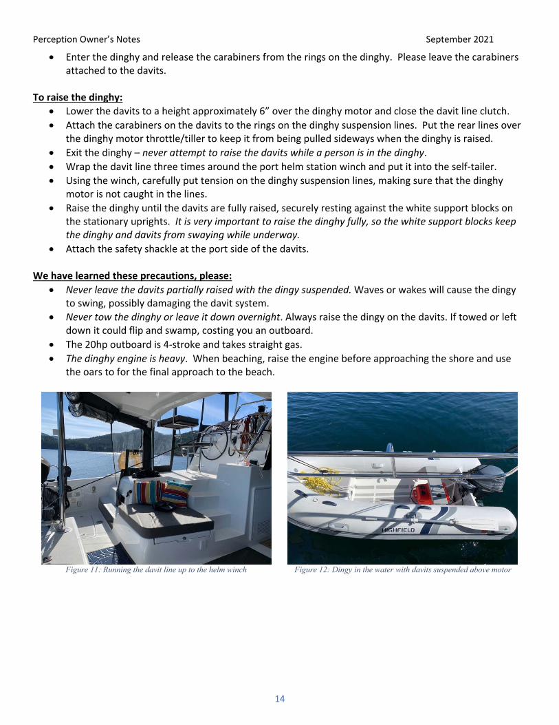
Figure 11: Running the davit line up to the helm winch
Figure 12: Dingy in the water with davits suspended above motor

Perception Owner’s Notes September 2021
15
Figure 13: Davit support block with davits securely seated
Figure 14: Davit safety shackle
Starting the Dinghy: Connect the engine shut-off cord to your wrist and snap the clip under the red kill switch. Open the air intake valve on the top of the gas tank and pump the bulb on the fuel line several times. The dinghy motor has an automatic choke, simply hold the throttle at the “start” position. Pull the starter cord out slowly until you feel resistance, then give a strong pull straight out. When cold it may take several pulls to get the engine to start. To shut off the dinghy, press the red kill switch for several seconds and close the air intake valve on top of the gas tank. Beaching the Dinghy: The dinghy motor is very heavy, making it difficult to take the dinghy up the beach. Use the dinghy anchor and bungee to keep the dinghy offshore while exploring the beach.
• Raise the motor and row the dinghy to shore as it can be challenging to raise the motor while surfing into the beach.
• Tie the dinghy painter to a secure object or have crew hold the painter. • Secure the bungee on the grapnel anchor to the dinghy, you may use the forward davit ring for this
purpose. • Row the dinghy out into deeper water and drop the grapnel anchor. • Return to shore stretching the bungee as you go. • Pay out the painter letting the bungee pull the dinghy out into deeper water. • Tie the dinghy painter to a secure object on shore.

Perception Owner’s Notes September 2021
16
11. Electrical Highlights
• The AC/DC Panel is located at the top of the starboard companionway. • The AC and DC panel breakers use the color dot convention shown at
right. • AC shore power primary breakers are located in the port hull engine
compartment, in the forward-starboard corner up high. They rarely trip but can be reset once if they do. If they trip a second time do not reset, call San Juan Sailing for advice.
• AC shore power secondary breaker is located on the AC/DC Panel and is labelled “Inverter”.
• Battery charger breaker is located on the AC side of the AC/DC panel at the Nav Station. • A set of circuit breakers for individual components in the boat may be found behind the forward panel
under the Nav Station. These should not normally trip.
Figure 15: AC/DC panel key
Figure 16: AC/DC Control Panel
Perception Owner’s Notes September 2021
17
12. Electronics/Instruments
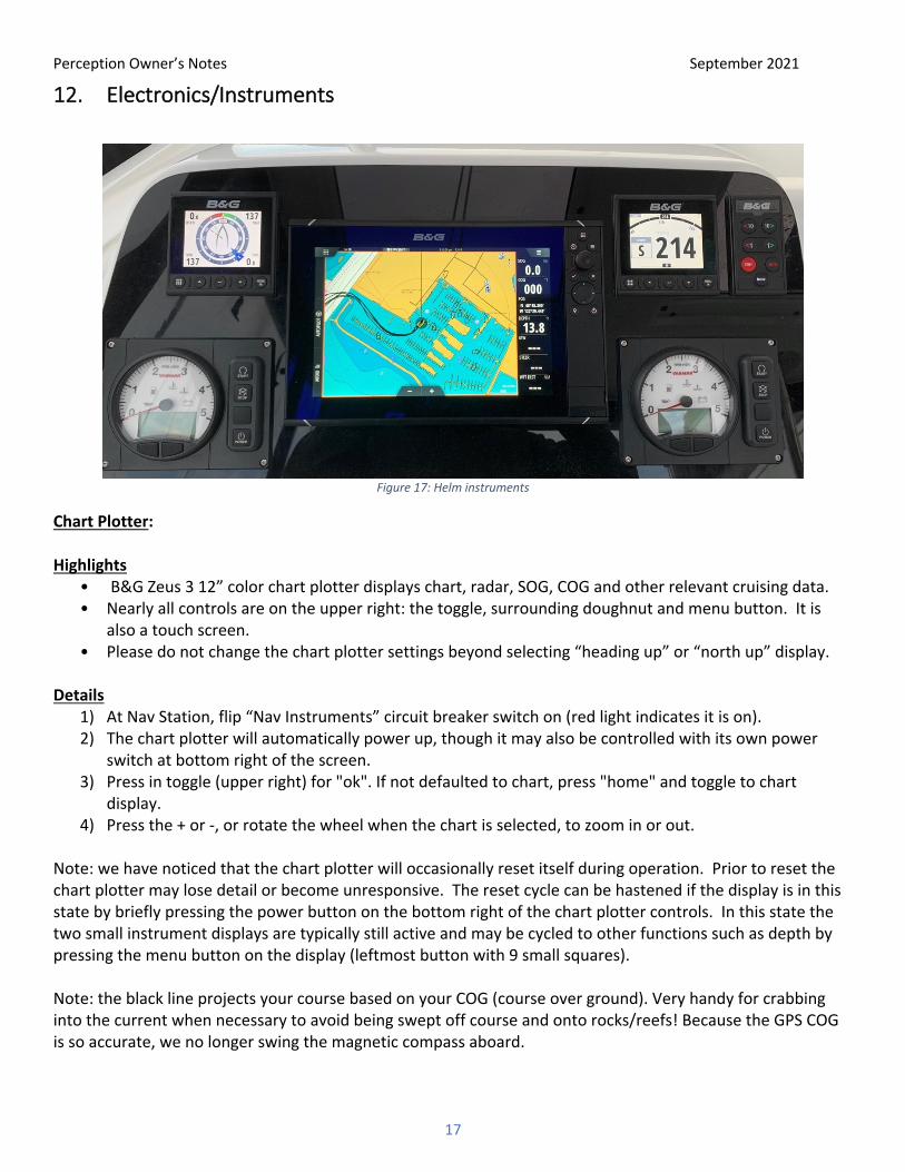
Figure 17: Helm instruments
Chart Plotter: Highlights
• B&G Zeus 3 12” color chart plotter displays chart, radar, SOG, COG and other relevant cruising data. • Nearly all controls are on the upper right: the toggle, surrounding doughnut and menu button. It is
also a touch screen. • Please do not change the chart plotter settings beyond selecting “heading up” or “north up” display.
Details
1) At Nav Station, flip “Nav Instruments” circuit breaker switch on (red light indicates it is on). 2) The chart plotter will automatically power up, though it may also be controlled with its own power
switch at bottom right of the screen. 3) Press in toggle (upper right) for "ok". If not defaulted to chart, press "home" and toggle to chart
display. 4) Press the + or -, or rotate the wheel when the chart is selected, to zoom in or out.
Note: we have noticed that the chart plotter will occasionally reset itself during operation. Prior to reset the chart plotter may lose detail or become unresponsive. The reset cycle can be hastened if the display is in this state by briefly pressing the power button on the bottom right of the chart plotter controls. In this state the two small instrument displays are typically still active and may be cycled to other functions such as depth by pressing the menu button on the display (leftmost button with 9 small squares). Note: the black line projects your course based on your COG (course over ground). Very handy for crabbing into the current when necessary to avoid being swept off course and onto rocks/reefs! Because the GPS COG is so accurate, we no longer swing the magnetic compass aboard.

Perception Owner’s Notes September 2021
18
To choose “heading up display” or “north up display”, press the menu button (indicated by three horizontal lines), use the wheel to select “More options”, then select “Orientation” to choose your preference. Again, please do not customize beyond this. The digital compass for the auto pilot is located in the starboard bilge at the bottom of the companionway. Placing anything magnetic in this area can cause the auto pilot to not work properly. This compass also feeds the boat’s current heading to the chart plotter, so something like a metal box, an electric toothbrush, or cell phone placed near this compass can cause both the auto pilot and chart plotter problems. We use the paper Maptec Chartbook for pre-planning, for continuous orientation underway and for pre-locating rocks and reefs on our planned route. We use the chart plotter to track our position underway in detail, for occasional confirmation of chart position, and for navigating in coves. Radar:
Highlight
• 4KW digital radar overlays onto chart display
Details The radar may be activated from the helm chart plotter. We typically use the radar as an overlay on top of chart data. To enter this mode, perform the following:
• Press the menu button (indicated by three horizontal lines), use the wheel to select “Overlay”, then choose “Radar”.
• To start transmitting, press the menu button, select “Radar Options”, then select “Transmit”. • To stop transmitting, press the menu button, select “Radar Options”, then select “Standby”. • From “home” you can also choose to show radar only or radar and chart plotter side by side. While we
normally leave the unit preset to radar overlay when the radar is activated; sometimes we find it beneficial to show a side-by-side display for greater radar clarity.
We do not cruise at night or in fog. The radar is especially useful should one be unpredictably enveloped in fog or heavy rain. If there is fog either visible or in the forecast, we stay at our mooring until it lifts (normally before noon). Safety is paramount. A.I.S. (Automatic Identification System): Highlights
• Perception transmits her position and data via an AIS signal as well as receives AIS signals from other vessels equipped with AIS transmitters (Commercial vessels are required to have AIS, recreational vessels are optional). Perception is transmitting her position full time (The AIS unit is wired directly to the batteries).
• The chart plotter is tied to the AIS Unit and shows the positions of vessels with AIS as triangles. • AIS information supplements marine radar, which continues to be the primary method of collision
avoidance for water transport. • AIS requires each vessel to have a 9-digit MMSI (Maritime Mobile Service Identity) number to transmit
position and data. Perception’s MMSI number is recorded in Section 1 of this document. Details

Perception Owner’s Notes September 2021
19
AIS vessels appear on the chart plotter screen as triangles. The triangle points in the direction that the vessel is moving and if you touch the screen over the triangle the system will pop up the name of the vessel. Pressing on the vessel name will give you a menu to find additional information (such as name, size, speed, bearing, etc.) about the vessel. The system also transmits this same type of information about Perception to other vessels with AIS.
AIS is an added safety feature which allows large commercial vessels to easily see you and your direction/speed. They may try to contact you via VHF channel 16 to verify your course intent. In addition, AIS allows San Juan Sailing/Yachting to provide faster assistance in case of unplanned maintenance issues as well as alert San Juan Sailing/Yachting of Perception’s return approach. Vessels with AIS can be viewed in real-time through mobile device apps and websites like www.marinetraffic.com that will reveal vessel name, course, speed, track, and other information.
Autopilot:
The autopilot may be used to hold heading when motoring or sailing. • Press “AUTO” button (at bottom right) to activate Heading Hold. • Press arrow keys to alter course to port or starboard by 1 deg or 10 deg increments. • Press “STBY” (Top right) to regain wheel steerage. • Must be in “STBY” to make quick heading changes to avoid other vessels or steer around
flotsam/jetsam, crab pot floats, etc. Depth Sounder: The B&G depth sounder is calibrated in feet and is set to read from the transducer, which is about a foot below water level. If you assume the reading is from the top of the water, you will have a very modest 1 foot safety margin. Due to rocks, we get nervous in anything less than 30 feet underway and 15 feet in an anchorage. The depth sounder is powered through the nav instruments circuit breaker. Please note that depth sounders sometimes give false readings in really deep water. In the San Juans, 400’-600’ are common depths in some channels and you may see false readings as the sensitivity on the transducer increases in an effort to give some reading, often from changes in water density, salinity, or underwater debris. Due to those changes in depth readings (especially in very deep water), we do not set depth alarms, but always know our position on the chart. Please note: You cannot rely on the depth sounder to avoid rocks! It is possible to go from 300’ to on the rocks in less than 30 seconds under sail in some areas! The answer is simple: we always plan our route on the chart and track our position on the chart plotter. Rocks are clearly marked. Knotmeter: You have two speed sources: speed through the water registered by the knotmeter on the small B&G Triton displays, and speed over ground (registered by the GPS on the chart plotter, which takes current into account). The knotmeter reads slightly faster on one tack than the other.

Perception Owner’s Notes September 2021
20
VHF radio: Highlights
• Icom base unit VHF radio at the Nav Station. Press and hold the large knob for three seconds to turn on/off.
• Icom VHF radio handset. Connected to the base station. The VHF system may be turned on/off by pressing the knob on the top of the handset for three seconds.
• Always monitor Ch 16. As the nearest vessel to an emergency, you may well be able to save a life or a boat.
• The VHF base unit radio does not need to be on to send and receive AIS data. See A.I.S. (Automatic Identification System) section above for detailed description of AIS.
Figure 18: VHF at the Nav Station
Figure 19: VHF handheld at the helm
Details For your convenience, we have “tagged” two channels for you: 80 (San Juan Sailing) and 16 (the emergency and contact channel). Please remember to touch the “16/C” button on the base unit or handset after each use so that you automatically monitor channel 16 while underway. To access weather channels, press the left/right buttons on the VHF base unit until the CH/WX option appears and press the button underneath it. Channel #4 or #7 are most often in range in the San Juan Islands. We listen for “Northern Inland Waters”. Pressing “CH/WX” again returns the normal channel.

Perception Owner’s Notes September 2021
21
13. Engines
Highlights • Yanmar 57hp 4 cylinder diesels, SD60 Saildrives, and 3 blade feathering Flexofold propellors. • The rear engine compartment hatches access the engines from the top for daily engine “lookover”.
This “before engine start” shows us in one quick view any black powder belt wear or loose belt, oil in bilge, eelgrass in strainer, or coolant spillage.
• Avoid excessive idling • 2000 rpm is economy cruise • 2200 rpm is cruising speed (green dot on tachometer) • 2500 rpm is emergency fast cruise (not longer than 10 minutes)
Details Raw water strainer is above water level. No need to open or clean unless the engine overheats but should be visually checked from the outside with a flashlight each morning prior to departure. If it’s necessary to clean it out, remove the lid carefully, making sure not to lose the O-ring. The strainer bowl should drain when the cover is removed. When replacing the lid, please avoid over-tightening. Oil dipstick access is on the starboard side of the engines. The engine is not known to use oil; nevertheless, a spare quart is inside the Cockpit locker. Mechanics check the oil levels weekly. To Start:
• There are no keys to start the engines, so make sure both engine battery switches are turned on (Port and Starboard engine compartments).
• Check all around the boat exterior to ensure no lines are in the water.
• Assure throttle/gearshift is in neutral. • Turn on the engine control panel – press the “I” button
at the bottom of the panel – see photo on right. • Start the engine by pressing the “Start” button at the
top of the panel – hold until engine is running – but no more than 5 seconds.
• Listen/look for the cooling water coming from the aft end of each hull.
• Most engines idle too long, causing carbon buildup. So if in a marina, we start the engine just before loosing lines. Same protocol if hoisting anchor or untying from a buoy—minimal idle. If starting after sailing, we allow one minute at 1200 rpm, another minute or so in gear at 1500 before resuming cruising speed.
Running: We are careful to pause 1-2 seconds after the “click” into gear before accelerating, to protect the transmission. And, of course, we always pause when changing from forward to reverse.
• 1200 rpm is about 4 knots—marina speed • 2000 rpm is economy cruise, about 6 knots, approx. 0.75 gph per engine, range: 67 hours, 400 NM • 2200 rpm is cruising speed, about 7.5 knots, approx. 1 gph per engine, range: 50 hours, 375 NM
Figure 20: Engine control panel
Perception Owner’s Notes September 2021
22
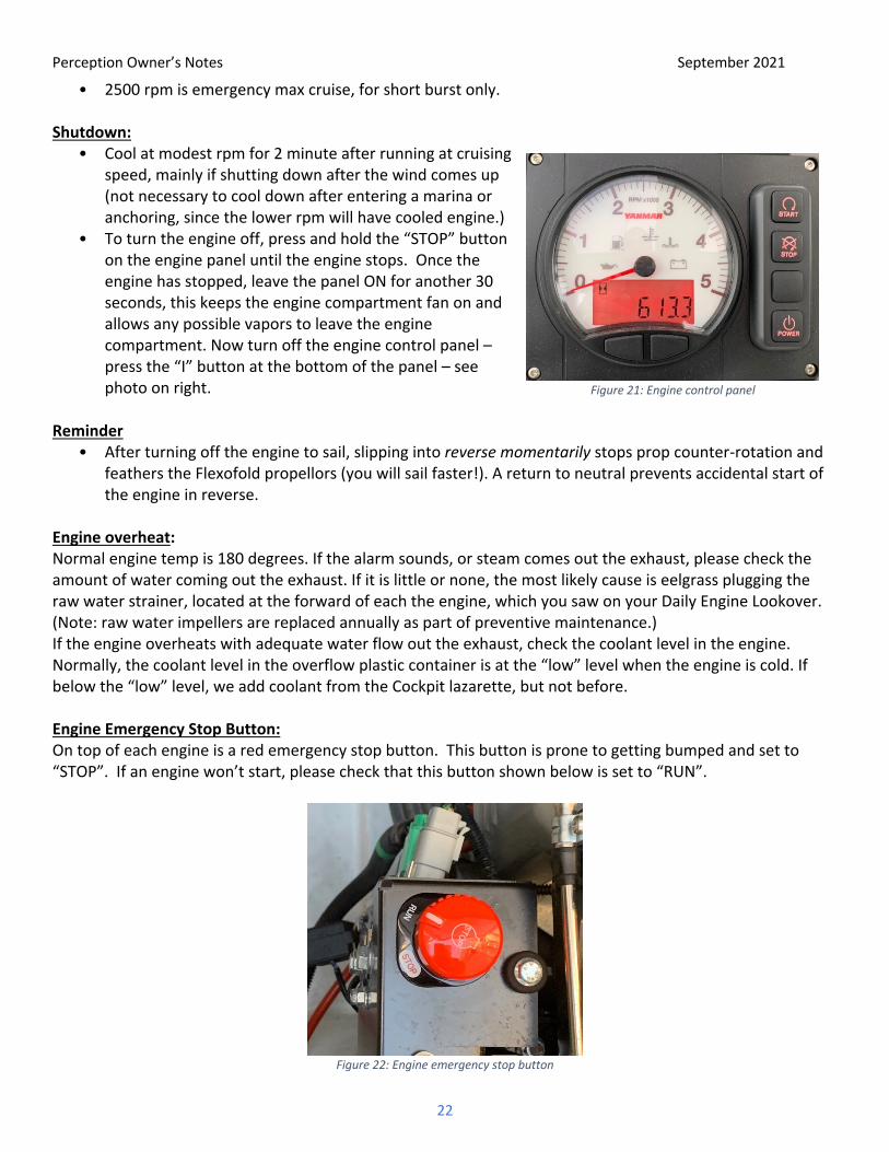
• 2500 rpm is emergency max cruise, for short burst only.
Shutdown: • Cool at modest rpm for 2 minute after running at cruising
speed, mainly if shutting down after the wind comes up (not necessary to cool down after entering a marina or anchoring, since the lower rpm will have cooled engine.)
• To turn the engine off, press and hold the “STOP” button on the engine panel until the engine stops. Once the engine has stopped, leave the panel ON for another 30 seconds, this keeps the engine compartment fan on and allows any possible vapors to leave the engine compartment. Now turn off the engine control panel – press the “I” button at the bottom of the panel – see photo on right.
Reminder
• After turning off the engine to sail, slipping into reverse momentarily stops prop counter-rotation and feathers the Flexofold propellors (you will sail faster!). A return to neutral prevents accidental start of the engine in reverse.
Engine overheat: Normal engine temp is 180 degrees. If the alarm sounds, or steam comes out the exhaust, please check the amount of water coming out the exhaust. If it is little or none, the most likely cause is eelgrass plugging the raw water strainer, located at the forward of each the engine, which you saw on your Daily Engine Lookover. (Note: raw water impellers are replaced annually as part of preventive maintenance.) If the engine overheats with adequate water flow out the exhaust, check the coolant level in the engine. Normally, the coolant level in the overflow plastic container is at the “low” level when the engine is cold. If below the “low” level, we add coolant from the Cockpit lazarette, but not before. Engine Emergency Stop Button: On top of each engine is a red emergency stop button. This button is prone to getting bumped and set to “STOP”. If an engine won’t start, please check that this button shown below is set to “RUN”.
Figure 22: Engine emergency stop button
Figure 21: Engine control panel

Perception Owner’s Notes September 2021
23
14. Entertainment Systems
Highlights ● Fusion MS-RA70N stereo located at the Nav Station in the Saloon. Bluetooth and radio. Speakers in Saloon and
Cockpit. ● Large TV Screen with cable for attaching devices. ● When shore power not available the Inverter will provide power to the TV.
Figure 23: Fusion stereo
Figure 24: Port aft stateroom TV
Details Fusion Stereo: Volume control – The Saloon and Cockpit speaker volumes can be adjusted separately:
a) Press the large black volume knob. The two volume zones will show in the display.
b) Press the center of the volume knob repeatedly until the volume you want to adjust is highlighted by vertical bars or both are highlighted if you want to adjust both together.
Mode Selection – There are four modes; AM Radio, FM Radio, Aux, and BT. Press the Arrow button on the upper right of the volume knob to change modes. Bluetooth – Select the BT mode. Turn on your device’s Bluetooth and connect to “PERCEPTION”. Television: The 32-inch smart TV is located in port-aft stateroom. If not connected to shore power, the Inverter will need to be turned on. Either way make sure the AC Outlets breaker on the AC/DC Panel is flipped on. A HDMI to HDMI and a USB to HDMI cable has been provided, as well as a multi-port hub for your convenience.
Figure 25: Stereo volume control
Figure 26: Television Adapter Hub
Perception Owner’s Notes September 2021
24
15. Fuel Highlights
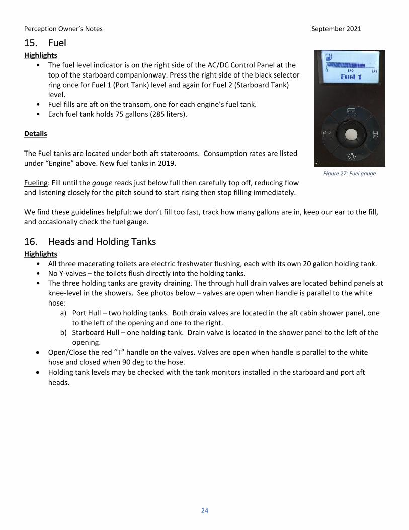
• The fuel level indicator is on the right side of the AC/DC Control Panel at the top of the starboard companionway. Press the right side of the black selector ring once for Fuel 1 (Port Tank) level and again for Fuel 2 (Starboard Tank) level.
• Fuel fills are aft on the transom, one for each engine’s fuel tank. • Each fuel tank holds 75 gallons (285 liters).
Details
The Fuel tanks are located under both aft staterooms. Consumption rates are listed under “Engine” above. New fuel tanks in 2019. Fueling: Fill until the gauge reads just below full then carefully top off, reducing flow and listening closely for the pitch sound to start rising then stop filling immediately. We find these guidelines helpful: we don’t fill too fast, track how many gallons are in, keep our ear to the fill, and occasionally check the fuel gauge.
16. Heads and Holding Tanks Highlights
• All three macerating toilets are electric freshwater flushing, each with its own 20 gallon holding tank. • No Y-valves – the toilets flush directly into the holding tanks. • The three holding tanks are gravity draining. The through hull drain valves are located behind panels at
knee-level in the showers. See photos below – valves are open when handle is parallel to the white hose:
a) Port Hull – two holding tanks. Both drain valves are located in the aft cabin shower panel, one to the left of the opening and one to the right.
b) Starboard Hull – one holding tank. Drain valve is located in the shower panel to the left of the opening.
• Open/Close the red “T” handle on the valves. Valves are open when handle is parallel to the white hose and closed when 90 deg to the hose.
• Holding tank levels may be checked with the tank monitors installed in the starboard and port aft heads.
Figure 27: Fuel gauge

Perception Owner’s Notes September 2021
25
Figure 28: Holding tank drain access panel
Figure 29: Drain valve in closed position
Details Rule of the Sea: The person who clogs the head, unclogs the head. Experienced sailor rule: To avoid the “rule of the sea” above, nothing goes down the toilet that hasn’t been digested. Please place feminine articles and toilet paper in the waste basket, plastic bag, or zip lock…makes for a much more pleasant cruise! The toilets can be flushed two ways. To flush in a more traditional manner, depress the switch pictured on the left and the waste will be evacuated and water will be added while you hold down the button. Liquid waste takes just a second, while for solid waste you will want to press and hold the button until the water you see in the toilet is clear (5-10 seconds). The switch pictured on the right can be used to add more water to the bowl by toggling it up, or to drain without adding additional water by toggling it down. Again, no paper is to be flushed down the head – if it hasn’t been through you, don’t flush it down the toilet! Holding Tanks: The three holding tanks are approximately 20 gallons each. One is located above each toilet. There is no Y valve. The holding tanks are above the water line. Each tank has a deck fitting for use at a pump out facility. Alternatively, the large red handle seacock, accessed under the floorboards as described in “Highlights” above, will evacuate the holding tank by gravity. We urge you to use shoreside facilities for solid effluent when moored in shallow bays and marinas where solid effluent has a measurable adverse impact…or the holding tank. Be aware that discharge in deep water is permissible in Canadian waters, but USCG regs prohibit such discharge in US waters.
Figure 30: Toilet flush control switches
Perception Owner’s Notes September 2021
26
If the holding tanks are overfilled, effluent will overflow through the vents, which gives foul odors and dirties the hull.
Depending upon the number and type of flushes above, and the number of people aboard, each holding tank may hold about two to three day's usage.
Emptying the Holding Tanks 1) Deck Pump-out: The holding tanks can be pumped out via the labeled deck fills. After pumping out the
holding tanks, please refill each tank with about 5 gallons of fresh water through the deck fitting to rinse, and then pump-out again. This will help keep the waste system smelling fresh! Thank you!
2) Overboard Discharge (where legal): The holding tanks are gravity drain, there is no macerator pump. They will normally drain in less than a minute (you may hear them finish with a ‘whoosh’ if the engine is not running). Open the large, red-handled seacocks located inside the cabinet of each head. Please make sure you close the seacock after the tank empties. If left open, then every time the toilet is flushed it will flow straight overboard!
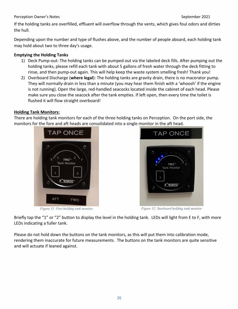
Holding Tank Monitors: There are holding tank monitors for each of the three holding tanks on Perception. On the port side, the monitors for the fore and aft heads are consolidated into a single monitor in the aft head.
Figure 31: Port holding tank monitor
Figure 32: Starboard holding tank monitor
Briefly tap the “1” or “2” button to display the level in the holding tank. LEDs will light from E to F, with more LEDs indicating a fuller tank. Please do not hold down the buttons on the tank monitors, as this will put them into calibration mode, rendering them inaccurate for future measurements. The buttons on the tank monitors are quite sensitive and will actuate if leaned against.

Perception Owner’s Notes September 2021
27
17. Heaters (Cabin Hydronic Heater) Highlights
• ITR Hurricane Hydronic Heater with hydronic/forced-air heat in the port engine compartment. • Hydronic fluid is heated by the Hurricane heater furnace and by the engines. • Heated hydronic fluid is pumped to forced-air heat exchangers in the Saloon and cabins. • Master control panel located at the Nav Station in the Saloon. • There are five individual thermostats to control forced-air heating: 2 in the Saloon and 1 in each of the
staterooms. • The heater will also provide hot water for the boat when the diesel furnace is running.
Figure 33: Hurricane heater control panel
Figure 34: Thermostat
Details The Hurricane hydronic/forced air heating system draws from the port diesel fuel tank. In our waters, we use the heater on cool evenings or to take the chill off in the morning. We normally turn off the heater at night to sleep cool, to avoid the sound of its fluid pump, and to save battery power if not on shore power. We will also use the hydronic heater to heat water for showers and dishes. As it takes some time to heat water, prepare by turning on the furnace 30 minutes ahead of planned usage when the water is cold. Turn on the cabin heater as follows:
a) Press the touchscreen of the master control panel. Press “ON” next to diesel heat to start the diesel furnace.
b) For each zone you want heated, press the top-right “sun” button on the thermostat and set the desired temperature (68-70 degrees best) using the arrow buttons.
c) For each zone you don’t want heated, press the top-left “moon” button on the thermostat and set the temperature to something low (64 degrees or lower).
d) If not on shore power, remember that the heater and fans will use battery power so monitor the house battery voltage. We usually turn the heater off at night while sleeping.
When on shore power the heater may also be run from AC power by turning on the “Electric Heat” option on the master control panel. The “Heater” breaker must be activated on the lower 120V AC panel for this mode.

Perception Owner’s Notes September 2021
28
The electric element for heating is relatively small and we typically find it useful only for maintaining temperature after first heating with the diesel furnace. Note that the engine will also heat the hydronic fluid used for the heaters. If you find the forced-air heaters active when the engines have been running, you may stop them by pressing the “moon” button at top-left on each thermostat and setting a low temperature. After stopping the engines the hydronic fluid pump in the port engine compartment will run as long as the fluid is warm and one or more forced-air heaters is running. You must stop all the heaters to stop the hydronic fluid pump in the port engine compartment. The Cockpit thermostat is located in the Saloon and is typically only useful when the Cockpit and Helm enclosures are closed and Saloon doors are open. Keep the thermostat for the Cockpit in “moon” mode with a low temperature setting to avoid wasting heat outdoors. You can test that the Cockpit heater is off by checking for airflow from the black vents on the forward edge of the transom.
18. Lighting Highlights
• Flip on the “Cabin Lights” breaker on the AC/DC control panel at the top of the starboard companionway.
• Saloon and Cockpit light switches are located on the inboard face of the galley cabinet next to the Saloon door.
• Port Hull light switches: a) Hallway – Two switches on the wall forward and aft of the stairs. b) Head – On the sink backsplash. Vanity lights about mirrors with switches on ends. c) Berth – Clamshell reading lights – each the clamshell to activate.
• Starboard Hull light switches: d) Hallway – On the wall immediately forward of the stairs. e) Head – On the forward end of the sink backsplash. f) Head vanity light above mirror has a switch on the end, charged by USB cord hanging in mirror
cabinet. Remove light from mounting brackets and plug into USB outlet. g) Cabins – On the inboard bulkheads inside the cabin doors. h) Berths – Clamshell reading lights – open each clamshell to activate.

Perception Owner’s Notes September 2021
29
19. Refrigeration and Freezer Highlights
• Circuit breaker is on the AC/DC control panel at the top of the starboard companionway. • We normally leave the fridge and freezer on 24 hours. They can be turned off at night to conserve
battery power, but this should typically not be necessary on Perception.
Details In addition to the standard side-loading refrigerator and top-loading freezer, Perception contains an Engel cooler/freezer inside the Saloon coffee table. Remove the coffee table mat to access. The temperature control on the unit may be set to cool or freeze.
Figure 35: Engle cooler/freezer in the coffee table
20. Sails and Rigging Highlights
• Full-battened main with Stack Pack, 100% furling jib. • All lines led to the helm station. • Single line mainsail reefing from helm station. • Apparent wind speed reefing guidelines in Details below.
Details Mainsail: We have a “stack pack” buckled boom cover and lazy jack system. No need to adjust the lazy jacks…just unbuckle and hoist. Raising:
a) Unbuckle the Stack Pack sail cover. b) Make sure that the clutches on the reef lines are open to let the main fully deploy. c) When not sailing the main halyard is normally attached to a loop on top of the hard bimini. When
attaching to the sail make sure that the main halyard leads inside all the lazy jacks.
Perception Owner’s Notes September 2021
30
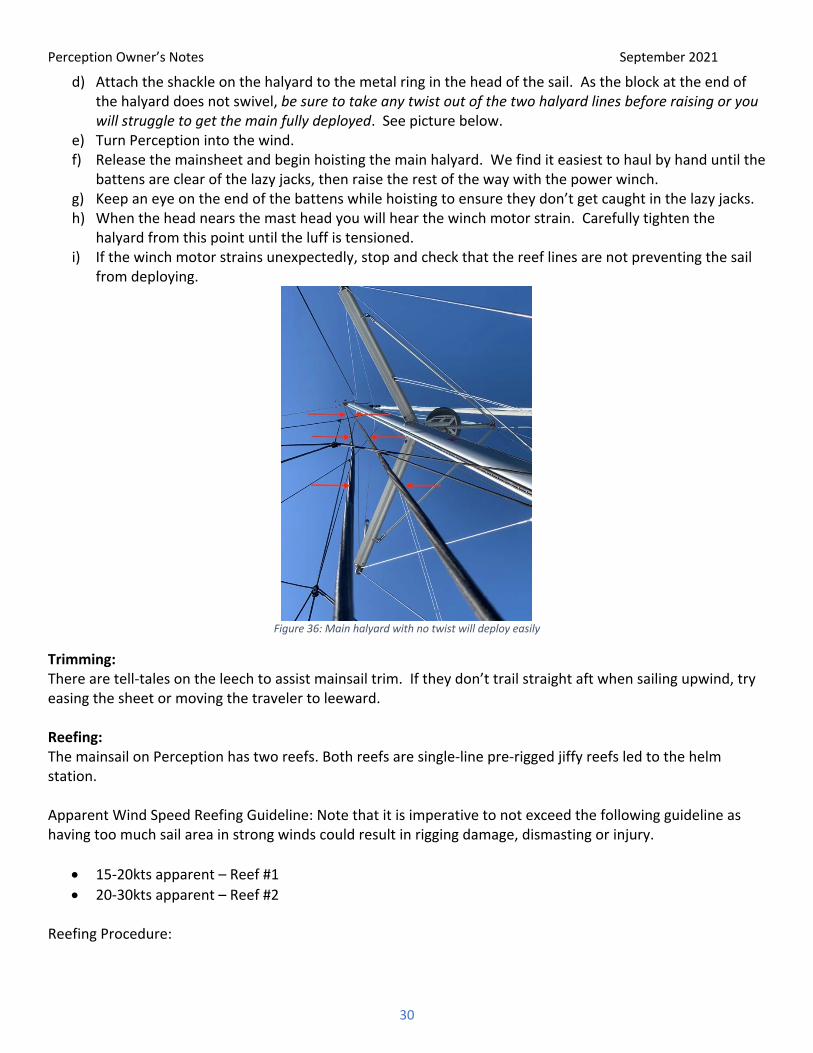
d) Attach the shackle on the halyard to the metal ring in the head of the sail. As the block at the end of the halyard does not swivel, be sure to take any twist out of the two halyard lines before raising or you will struggle to get the main fully deployed. See picture below.
e) Turn Perception into the wind. f) Release the mainsheet and begin hoisting the main halyard. We find it easiest to haul by hand until the
battens are clear of the lazy jacks, then raise the rest of the way with the power winch. g) Keep an eye on the end of the battens while hoisting to ensure they don’t get caught in the lazy jacks. h) When the head nears the mast head you will hear the winch motor strain. Carefully tighten the
halyard from this point until the luff is tensioned. i) If the winch motor strains unexpectedly, stop and check that the reef lines are not preventing the sail
from deploying.
Figure 36: Main halyard with no twist will deploy easily
Trimming: There are tell-tales on the leech to assist mainsail trim. If they don’t trail straight aft when sailing upwind, try easing the sheet or moving the traveler to leeward. Reefing: The mainsail on Perception has two reefs. Both reefs are single-line pre-rigged jiffy reefs led to the helm station. Apparent Wind Speed Reefing Guideline: Note that it is imperative to not exceed the following guideline as having too much sail area in strong winds could result in rigging damage, dismasting or injury.
• 15-20kts apparent – Reef #1 • 20-30kts apparent – Reef #2
Reefing Procedure:
Perception Owner’s Notes September 2021
31
a) With the mainsheet eased and Perception headed upwind (close hauled if under sail or head to wind if under power and the jib furled) ease the halyard until the reef #1 grommet at the luff is 1’ above the boom then cleat off the halyard.
b) While the main is lowering, pull in the slack on the #1 Reef line. c) After the halyard if cleated, put the #1 reef line on a winch and tighten just enough to remove slack
from the luff and foot. d) If going directly to #2 reef, skip step c) above and continue lowering the main until the reef #2
grommet at the luff is 1’ above the boom then cleat off the halyard. e) While the main is lowering, pull in the slack on the #2 Reef line. f) After the halyard if cleated, put the #2 reef line on a winch and tighten just enough to remove slack
from the luff and foot. Jib: The jib is self-tacking but occasionally when the wind is light, or the jib sheet is tight it won’t tack easily. Try easing the sheet a foot or so just prior to making your turn. In light winds you may have to go forward and pull the jib across.
The jib furling line is a line led along the port deck. It is not recommended to reef the jib. It should be either completely furled or if conditions allow, completely unfurled.
21. Showers and Sumps Highlights
• Separate shower stall in starboard cabin • Separate shower stall in port aft cabin • Separate head shower in port forward cabin • Starboard freshwater transom shower (Hot and cold) • Pump switches in shower stall, no sump or float switches • CAUTION: Water can be scalding hot. Be very careful to adjust temperature appropriately. For best
results, use half pressure and avoid a scalding/freezing cyclical shower. PLEASE ASSIST CHILDREN! • The hot water tank is in the port hull under the aft berth. For an easier and more comfortable shower
in the starboard hull, run the water in the sink in the starboard head until hot, then turn on the shower. It takes some time for hot water to get all the way to the other side of the boat.
Details Shower Sump Pumps: A button in each shower operates the sump pump for approximately 15 seconds. There is no float switch, so while showering periodically push the sump pump button to dump the gray water overboard. This should be done proactively to prevent water from backing up onto the floor of the heads. Note: shower sumps can become emergency bilge pumps if water rises to that level. Transom Shower: The transom shower is in the compartment on the starboard hull above the transom steps. The shower features both hot and cold water. To operate, pull the shower hose out of the compartment and push the T-handle aft to pressurize the hose. Turn the T-handle left or right to adjust temperature. Depress the shower head trigger for spray.

Perception Owner’s Notes September 2021
32
When done with the shower push the T-handle forward to depressurize the hose, release the remaining hose pressure by triggering the nozzle, and return the hose to the compartment.
22. Spares and Tools Tools and common spares are located in the saloon seat bench locker on the port side. Long term and engine spares are located in a plastic tub in the port forepeak.
23. Storage You won’t struggle to find places to stow provisions on this catamaran. Food: 1 – Baskets mounted under upper cabinets allow ample room for dry goods storage. 2 – 2 floor hatches in galley area are great for storing drinks. 3 – Starboard hull has bookshelves and cabinets for surplus food storage. Clothes: Each stateroom has a hanging locker, shelf cabinet, and under bed drawers. Luggage: Luggage is easily stored in port forepeak or under bed in third cabin (access through cabinet door between under bed drawers. Cooking utensils: long handled utensils located in utensil can behind stove. Other assorted kitchen tools and eating utensils located in galley drawer. Knives located in wood block behind stove. Pots and Pans: Everyday pots and pans are stored in the cabinet above the dish drainer. Lids and larger skillet are stored in the lower cabinet below the food preparation counter. Large cookware and the crab pot and crackers are stowed in the middle seat locker in the Saloon. Fenders and Dock lines: Bridgedeck starboard locker when not in use.
Tools: Saloon bench seat near port hull ladder Trash: Trash can be DOUBLE BAGGED and stowed in the starboard forepeak in the plastic tub labeled TRASH until you are in a marina where you can dispose of it. Please be mindful of leaky/funky trash that could leave lasting odor in the fiberglass hull.
24. Stove/Oven, Microwave, Keurig Coffeemaker Highlights
• The stove/oven are propane-fired. • The microwave oven is plugged into a 120V outlet in the galley. • The propane solenoid switch is located on the electrical panel at the top of the starboard hull ladder. • There are two 4.5 gallon steel propane tanks in the Cockpit seat locker next to the Saloon bulkhead. The locker is
vented overboard for safety. (You will notice a propane smell in the propane locker itself as the fiberglass absorbs the odor of propane.)

Perception Owner’s Notes September 2021
33
• The San Juan Sailing staff checks these tanks weekly to assure that you don’t run out. • For safety, we turn off the solenoid switch after stove use. • If not connected to shore power the microwave can be powered by the battery inverter. Please only use for
short (1-2 minute) cook times if the sun isn’t out or you will rapidly drain the house batteries. • Caution: propane is heavier than air. If leak is detected, extinguish all flames and open all hatches and doors.
Details
Lighting a Stove Burner:
• Make sure the propane tank hand valve is open and the solenoid valve switch is on. • Depress the striker button while pushing the burner temperature knob to the “light” (flame symbol) position. If
striker doesn’t work, check black burner covers to make sure they are properly seated. If they are and burner still won’t light, try using a BBQ lighter instead of the striker button.
• After the burner lights, hold the knob in for a few seconds to heat the safety “thermocouple”, then release. • Turn the knob to the desired heat level. • If needed, the stove potholder arms can be found in the storage basket above the microwave and attached with
the hardware in the Ziploc bag.
Lighting the Oven Burner:
• Make sure the propane tank hand valve is open and the solenoid valve switch is on. • Open the oven door. • Push the oven temperature knob in and turn to the high flame symbol while depressing the striker button. • After the burner lights, hold the knob in for a few seconds to heat the safety “thermocouple”, then release. • Turn the knob to the desired heat level. • If striker doesn’t light it, use a BBQ lighter.
Microwave Oven:
• Located on the counter behind the sink faucet. • Make sure the OUTLETS switch on the electrical panel is ON. • If not connected to shore power the microwave can be powered by the battery inverter. Please only use for
short (1-2 minute) cook times if sun is not out or you will rapidly drain the house batteries. See Section 6, Batteries/Charging/Inverter for instructions on how to use the inverter.
Keurig Coffeemaker:
• Located on the counter above the refrigerator. • When not connected to shore power, use caution when operating as it can rapidly drain the house batteries if
the sun is not out. • Make sure the OUTLETS switch on the electrical panel is ON. Plug in, turn power button on, dispense mug of
water (6-12 ounces) in water tank and place mug on drip tray. Lift the grey handle and place a K-cup compatible coffee pod into the holder, lower the handle and press the Press the brew button. The brew indicator light will illuminate solid, then begin to pulse while the brewer is heating. After about 2 minutes, the brew indicator light will illuminate solid again and the beverage will begin to dispense. Brewing is complete when the brew indicator light is no longer illuminated.
Perception Owner’s Notes September 2021
34
25. Vacuum Highlights
• Hoover battery powered upright vacuum is located in starboard hull tall cabinet and the battery charger is in the hanging cubby in the same cabinet.
• Store by opening vacuum to the fully reclined position, tuck the handle under the bracket in the corner and rest the foot behind the angled wood rail.
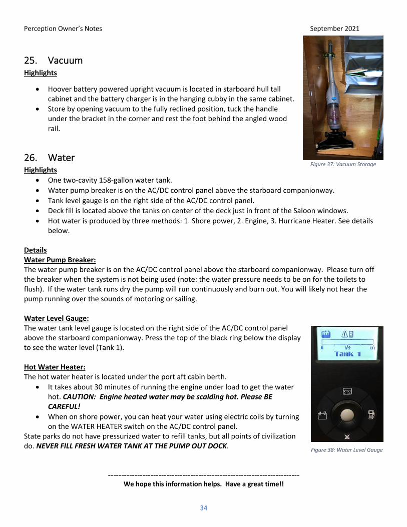
26. Water Highlights
• One two-cavity 158-gallon water tank. • Water pump breaker is on the AC/DC control panel above the starboard companionway. • Tank level gauge is on the right side of the AC/DC control panel. • Deck fill is located above the tanks on center of the deck just in front of the Saloon windows. • Hot water is produced by three methods: 1. Shore power, 2. Engine, 3. Hurricane Heater. See details
below. Details Water Pump Breaker: The water pump breaker is on the AC/DC control panel above the starboard companionway. Please turn off the breaker when the system is not being used (note: the water pressure needs to be on for the toilets to flush). If the water tank runs dry the pump will run continuously and burn out. You will likely not hear the pump running over the sounds of motoring or sailing. Water Level Gauge: The water tank level gauge is located on the right side of the AC/DC control panel above the starboard companionway. Press the top of the black ring below the display to see the water level (Tank 1). Hot Water Heater: The hot water heater is located under the port aft cabin berth.
• It takes about 30 minutes of running the engine under load to get the water hot. CAUTION: Engine heated water may be scalding hot. Please BE CAREFUL!
• When on shore power, you can heat your water using electric coils by turning on the WATER HEATER switch on the AC/DC control panel.
State parks do not have pressurized water to refill tanks, but all points of civilization do. NEVER FILL FRESH WATER TANK AT THE PUMP OUT DOCK.
------------------------------------------------------------------------ We hope this information helps. Have a great time!!
Figure 38: Water Level Gauge
Figure 37: Vacuum Storage