perceiving translucent materials
TRANSCRIPT
Perceiving translucent materialsRoland W. Fleming1, Henrik Wann Jensen2 & Heinrich H Bülthoff1
1Max Planck Institute for Biological Cybernetics.2Computer Graphics Laboratory, UCSD.
Abstract
Many common materials, including fruit, wax and human skin,are somewhat translucent. What makes an object looktranslucent or opaque? Here we use a recently developedcomputer graphics model of subsurface light transport [Jensen, etal., 2001] to study the factors that determine perceivedtranslucency. We discuss how physical factors, such as light-source direction can alter the apparent translucency of an object,finding that objects are perceived to be more translucent whenilluminated from behind than in front. We also study the role ofa range of image cues, including colour, contrast and blur, in theperception of translucency. Although we learn a lot aboutimages of translucent materials, we find that many simplecandidate sources of information fail to predict how translucentan object looks. We suggest that the visual system does not relysolely on these simple image statistics to estimate translucency:the relevant stimulus information remains to be discovered.
CR Categories: J.4 [Computer Application]: Social andBehavioral Sciences; I.3.7. [Computer Graphics] Three-dimensional Graphics and Realism.
Keywords: subsurface scattering; perception; psychophysics.
1. Introduction
Many materials that we commonly encounter aretranslucent, including leaves and fruit flesh; textiles and papers;various stones, such as agate or marble; soaps; wax; some typesof glass; milk and human skin. How do we recognize thesematerials? What image cues allow us to tell that a surface istranslucent rather than opaque? Here we use a combination ofpsychophysics and computational image analysis to study theimage properties that underlie the distinctive appearance oftranslucent materials.
When light strikes a translucent material, it enters the bodyof the object, scatters, and re-emerges from the surface. Thelight that bleeds through translucent objects gives them acharacteristic softness and glow. However, although light isvisible through translucent objects, form is generally not. Thishas profound consequences for the image cues underlyingtranslucency perception, and results from the way that lightscatters beneath the surface of an object.
Subsurface light transport
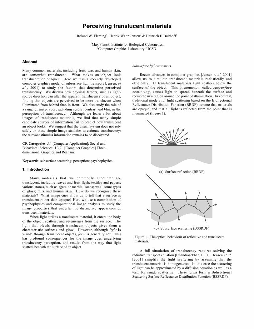
Recent advances in computer graphics [Jensen et al. 2001]allow us to simulate translucent materials realistically andefficiently. In translucent materials light scatters below thesurface of the object. This phenomenon, called subsurfacescattering, causes light to spread beneath the surface andreemerge in a region around the point of illumination. In contrast,traditional models for light scattering based on the BidirectionalReflectance Distribution Function (BRDF) assume that materialsare opaque, and that all light is reflected from the point that isilluminated (Figure 1).
(a) Surface reflection (BRDF)
(b) Subsurface scattering (BSSRDF)
Figure 1. The optical behaviour of reflective and translucentmaterials.
A full simulation of translucency requires solving theradiative transport equation [Chandrasekhar, 1961]. Jensen et al.[2001] simplify the light scattering by assuming that thetranslucent material is homogeneous. In this case the scatteringof light can be approximated by a diffusion equation as well as aterm for single scattering. These terms form a BidirectionalScattering Surface Reflectance Distribution Function (BSSRDF).
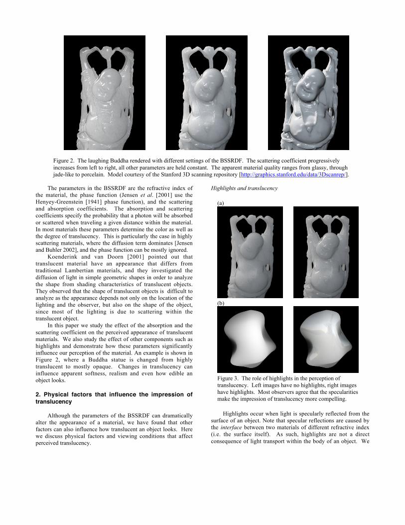
Figure 2. The laughing Buddha rendered with different settings of the BSSRDF. The scattering coefficient progressivelyincreases from left to right, all other parameters are held constant. The apparent material quality ranges from glassy, throughjade-like to porcelain. Model courtesy of the Stanford 3D scanning repository [http://graphics.stanford.edu/data/3Dscanrep/].
The parameters in the BSSRDF are the refractive index ofthe material, the phase function (Jensen et al. [2001] use theHenyey-Greenstein [1941] phase function), and the scatteringand absorption coefficients. The absorption and scatteringcoefficients specify the probability that a photon will be absorbedor scattered when traveling a given distance within the material.In most materials these parameters determine the color as well asthe degree of translucency. This is particularly the case in highlyscattering materials, where the diffusion term dominates [Jensenand Buhler 2002], and the phase function can be mostly ignored.
Koenderink and van Doorn [2001] pointed out thattranslucent material have an appearance that differs fromtraditional Lambertian materials, and they investigated thediffusion of light in simple geometric shapes in order to analyzethe shape from shading characteristics of translucent objects.They observed that the shape of translucent objects is difficult toanalyze as the appearance depends not only on the location of thelighting and the observer, but also on the shape of the object,since most of the lighting is due to scattering within thetranslucent object.
In this paper we study the effect of the absorption and thescattering coefficient on the perceived appearance of translucentmaterials. We also study the effect of other components such ashighlights and demonstrate how these parameters significantlyinfluence our perception of the material. An example is shown inFigure 2, where a Buddha statue is changed from highlytranslucent to mostly opaque. Changes in translucency caninfluence apparent softness, realism and even how edible anobject looks.
2. Physical factors that influence the impression oftranslucency
Although the parameters of the BSSRDF can dramaticallyalter the appearance of a material, we have found that otherfactors can also influence how translucent an object looks. Herewe discuss physical factors and viewing conditions that affectperceived translucency.
Highlights and translucency
(a)
(b)
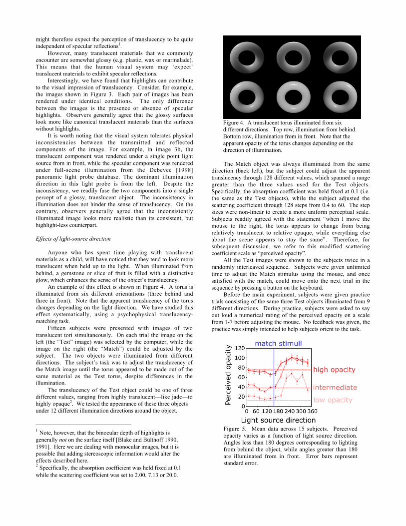
Figure 3. The role of highlights in the perception oftranslucency. Left images have no highlights, right imageshave highlights. Most observers agree that the specularitiesmake the impression of translucency more compelling.
Highlights occur when light is specularly reflected from thesurface of an object. Note that specular reflections are caused bythe interface between two materials of different refractive index(i.e. the surface itself). As such, highlights are not a directconsequence of light transport within the body of an object. We
might therefore expect the perception of translucency to be quiteindependent of specular reflections1.
However, many translucent materials that we commonlyencounter are somewhat glossy (e.g. plastic, wax or marmalade).This means that the human visual system may ‘expect’translucent materials to exhibit specular reflections.
Interestingly, we have found that highlights can contributeto the visual impression of translucency. Consider, for example,the images shown in Figure 3. Each pair of images has beenrendered under identical conditions. The only differencebetween the images is the presence or absence of specularhighlights. Observers generally agree that the glossy surfaceslook more like canonical translucent materials than the surfaceswithout highlights.
It is worth noting that the visual system tolerates physicalinconsistencies between the transmitted and reflectedcomponents of the image. For example, in image 3b, thetranslucent component was rendered under a single point lightsource from in front, while the specular component was renderedunder full-scene illumination from the Debevec [1998]panoramic light probe database. The dominant illuminationdirection in this light probe is from the left. Despite theinconsistency, we readily fuse the two components into a singlepercept of a glossy, translucent object. The inconsistency inillumination does not hinder the sense of translucency. On thecontrary, observers generally agree that the inconsistentlyilluminated image looks more realistic than its consistent, buthighlight-less counterpart.
Effects of light-source direction
Anyone who has spent time playing with translucentmaterials as a child, will have noticed that they tend to look moretranslucent when held up to the light. When illuminated frombehind, a gemstone or slice of fruit is filled with a distinctiveglow, which enhances the sense of the object’s translucency.
An example of this effect is shown in Figure 4. A torus isilluminated from six different orientations (three behind andthree in front). Note that the apparent translucency of the toruschanges depending on the light direction. We have studied thiseffect systematically, using a psychophysical translucency-matching task.
Fifteen subjects were presented with images of twotranslucent tori simultaneously. On each trial the image on theleft (the “Test” image) was selected by the computer, while theimage on the right (the “Match”) could be adjusted by thesubject. The two objects were illuminated from differentdirections. The subject’s task was to adjust the translucency ofthe Match image until the torus appeared to be made out of thesame material as the Test torus, despite differences in theillumination.
The translucency of the Test object could be one of threedifferent values, ranging from highly translucent—like jade—tohighly opaque2. We tested the appearance of these three objectsunder 12 different illumination directions around the object.
1 Note, however, that the binocular depth of highlights isgenerally not on the surface itself [Blake and Bülthoff 1990,1991]. Here we are dealing with monocular images, but it ispossible that adding stereoscopic information would alter theeffects described here.2 Specifically, the absorption coefficient was held fixed at 0.1while the scattering coefficient was set to 2.00, 7.13 or 20.0.
Figure 4. A translucent torus illuminated from sixdifferent directions. Top row, illumination from behind.Bottom row, illumination from in front. Note that theapparent opacity of the torus changes depending on thedirection of illumination.
The Match object was always illuminated from the samedirection (back left), but the subject could adjust the apparenttranslucency through 128 different values, which spanned a rangegreater than the three values used for the Test objects.Specifically, the absorption coefficient was held fixed at 0.1 (i.e.the same as the Test objects), while the subject adjusted thescattering coefficient through 128 steps from 0.4 to 60. The stepsizes were non-linear to create a more uniform perceptual scale.Subjects readily agreed with the statement “when I move themouse to the right, the torus appears to change from beingrelatively translucent to relative opaque, while everything elseabout the scene appears to stay the same”. Therefore, forsubsequent discussion, we refer to this modified scatteringcoefficient scale as “perceived opacity”.
All the Test images were shown to the subjects twice in arandomly interleaved sequence. Subjects were given unlimitedtime to adjust the Match stimulus using the mouse, and oncesatisfied with the match, could move onto the next trial in thesequence by pressing a button on the keyboard.
Before the main experiment, subjects were given practicetrials consisting of the same three Test objects illuminated from 9different directions. During practice, subjects were asked to sayout loud a numerical rating of the perceived opacity on a scalefrom 1-7 before adjusting the mouse. No feedback was given, thepractice was simply intended to help subjects orient to the task.
Figure 5. Mean data across 15 subjects. Perceivedopacity varies as a function of light source direction.Angles less than 180 degrees corresponding to lightingfrom behind the object, while angles greater than 180are illuminated from in front. Error bars representstandard error.
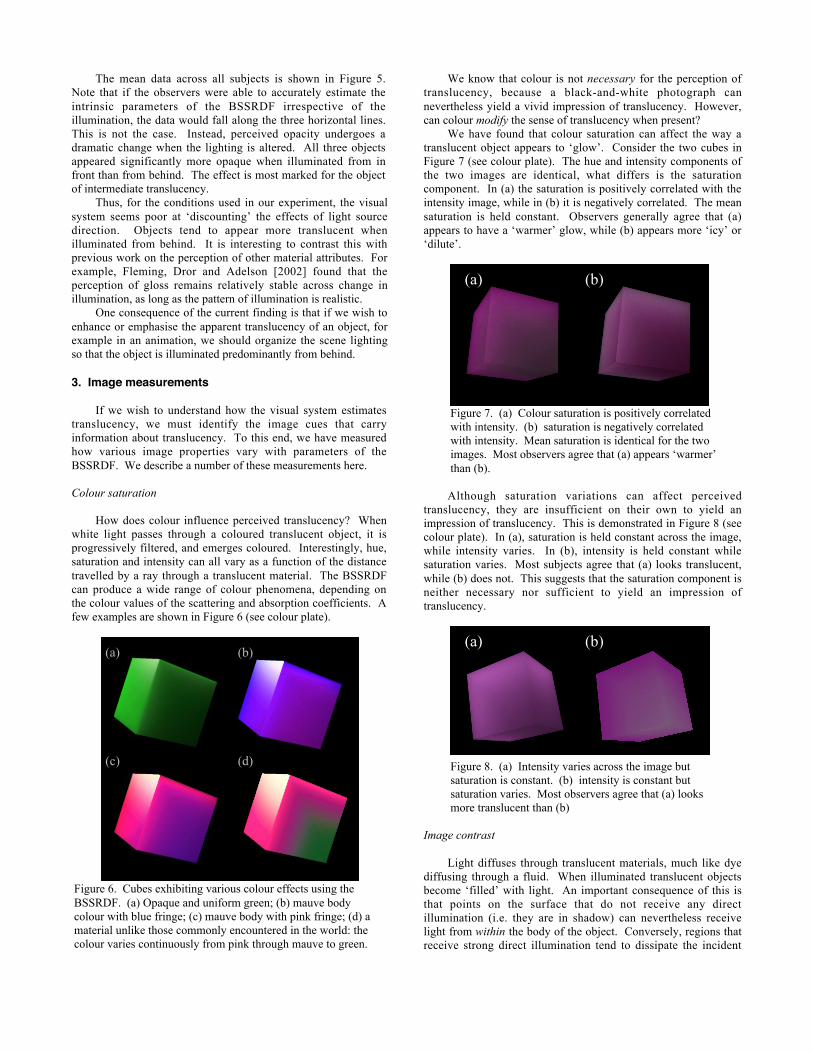
The mean data across all subjects is shown in Figure 5.Note that if the observers were able to accurately estimate theintrinsic parameters of the BSSRDF irrespective of theillumination, the data would fall along the three horizontal lines.This is not the case. Instead, perceived opacity undergoes adramatic change when the lighting is altered. All three objectsappeared significantly more opaque when illuminated from infront than from behind. The effect is most marked for the objectof intermediate translucency.
Thus, for the conditions used in our experiment, the visualsystem seems poor at ‘discounting’ the effects of light sourcedirection. Objects tend to appear more translucent whenilluminated from behind. It is interesting to contrast this withprevious work on the perception of other material attributes. Forexample, Fleming, Dror and Adelson [2002] found that theperception of gloss remains relatively stable across change inillumination, as long as the pattern of illumination is realistic.
One consequence of the current finding is that if we wish toenhance or emphasise the apparent translucency of an object, forexample in an animation, we should organize the scene lightingso that the object is illuminated predominantly from behind.
3. Image measurements
If we wish to understand how the visual system estimatestranslucency, we must identify the image cues that carryinformation about translucency. To this end, we have measuredhow various image properties vary with parameters of theBSSRDF. We describe a number of these measurements here.
Colour saturation
How does colour influence perceived translucency? Whenwhite light passes through a coloured translucent object, it isprogressively filtered, and emerges coloured. Interestingly, hue,saturation and intensity can all vary as a function of the distancetravelled by a ray through a translucent material. The BSSRDFcan produce a wide range of colour phenomena, depending onthe colour values of the scattering and absorption coefficients. Afew examples are shown in Figure 6 (see colour plate).
Figure 6. Cubes exhibiting various colour effects using theBSSRDF. (a) Opaque and uniform green; (b) mauve bodycolour with blue fringe; (c) mauve body with pink fringe; (d) amaterial unlike those commonly encountered in the world: thecolour varies continuously from pink through mauve to green.
We know that colour is not necessary for the perception oftranslucency, because a black-and-white photograph cannevertheless yield a vivid impression of translucency. However,can colour modify the sense of translucency when present?
We have found that colour saturation can affect the way atranslucent object appears to ‘glow’. Consider the two cubes inFigure 7 (see colour plate). The hue and intensity components ofthe two images are identical, what differs is the saturationcomponent. In (a) the saturation is positively correlated with theintensity image, while in (b) it is negatively correlated. The meansaturation is held constant. Observers generally agree that (a)appears to have a ‘warmer’ glow, while (b) appears more ‘icy’ or‘dilute’.
Figure 7. (a) Colour saturation is positively correlatedwith intensity. (b) saturation is negatively correlatedwith intensity. Mean saturation is identical for the twoimages. Most observers agree that (a) appears ‘warmer’than (b).
Although saturation variations can affect perceivedtranslucency, they are insufficient on their own to yield animpression of translucency. This is demonstrated in Figure 8 (seecolour plate). In (a), saturation is held constant across the image,while intensity varies. In (b), intensity is held constant whilesaturation varies. Most subjects agree that (a) looks translucent,while (b) does not. This suggests that the saturation component isneither necessary nor sufficient to yield an impression oftranslucency.
Figure 8. (a) Intensity varies across the image butsaturation is constant. (b) intensity is constant butsaturation varies. Most observers agree that (a) looksmore translucent than (b)
Image contrast
Light diffuses through translucent materials, much like dyediffusing through a fluid. When illuminated translucent objectsbecome ‘filled’ with light. An important consequence of this isthat points on the surface that do not receive any directillumination (i.e. they are in shadow) can nevertheless receivelight from within the body of the object. Conversely, regions thatreceive strong direct illumination tend to dissipate the incident
(a) (b)
(c) (d)
(a) (b)
(a) (b)

light by transmitting it to other parts of the object. This has theeffect of reducing the overall contrast of translucent objects.Figure 9 shows an example of this. Three objects are shownunder the same lighting. Torus A is the most translucent, TorusB is of intermediate translucency, while Torus C is relativelyopaque. Note that the range of intensities in the imagesprogressively increases from A to C. It seems reasonable, then,that the human visual system might use image contrast toestimate the opacity of an object. In this section, we discuss therole of image contrast in the perception of translucency.
Figure 9. Three tori in increasing order of opacity.Note that the range of intensities in the images increasesfrom A to C.
How should we define contrast? It is common to alter thecontrast and brightness of an image using a linear (affine)transformation of the image intensities. Specifically, to adjustcontrast, intensities are multiplicatively scaled, while to adjustbrightness, image intensities are additively scaled. Can we usethe concept of linear transformations to understand therelationship between opaque and translucent objects?
Figure 10 directly compares Torus A with Torus C. If weplot the intensities of the translucent torus on the x-axis, and theintensities of corresponding locations in the opaque torus on they-axis, we see that the two images are not linearly related to oneanother.
Figure 10. The non-linear relationship betweenintensity values in Torus A and Torus C.
This is important because it affects our concept of contrast.Specifically, it excludes any definition that assumes linearity.This is highlighted if we take Torus B, and try to adjust the imageintensities to make it appear like Torus A or Torus C. If wemodify the image intensities according to the best-fitting lineartransform, we get the results shown in Figure 11.
Figure 11. Here we linearly adjust the intensities ofTorus B to try to make the image appear as translucentas Torus A and as opaque as Torus C.
Although these transforms offer the best compromisebetween matching the brightness and contrast of the images, wesee that they fail to match the apparent translucency of theobjects. This is especially clear for the low-contrast image, whichlooks considerably less translucent than the target image (TorusA).
When we gradually alter an object from translucent toopaque, we see that the entire distribution of image intensitieschanges shape (Figure 12). The mode shifts to lower intensities,while the whole distribution becomes more skewed. This
Torus A
Torus B
Torus C
Torus B linearly adjusted tomatch contrast of Torus A
Torus B linearly adjusted tomatch contrast of Torus C
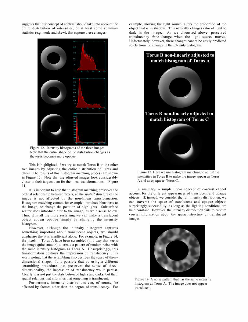
suggests that our concept of contrast should take into account theentire distribution of intensities, or at least some summarystatistics (e.g. mode and skew), that capture these changes.
Figure 12. Intensity histograms of the three images.Note that the entire shape of the distribution changes asthe torus becomes more opaque.
This is highlighted if we try to match Torus B to the othertwo images by adjusting the entire distribution of lights anddarks. The results of this histogram matching process are shownin Figure 13. Note that the adjusted images look considerablycloser to their targets than for the linear transformations in Figure11.
It is important to note that histogram matching preserves theordinal relationship between pixels, so the spatial structure of theimage is not affected by the non-linear transformation.Histogram matching cannot, for example, introduce blurriness tothe image, or change the position of highlights. Subsurfacescatter does introduce blur to the image, as we discuss below.Thus, it is all the more surprising we can make a translucentobject appear opaque simply by changing the intensityhistogram.
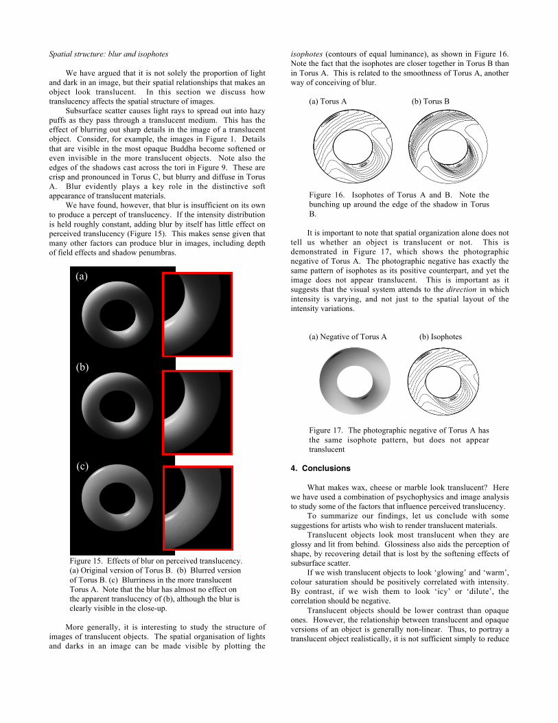
However, although the intensity histogram capturessomething important about translucent objects, we shouldemphasise that it is insufficient alone. For example, in Figure 14,the pixels in Torus A have been scrambled (in a way that keepsthe image quite smooth) to create a pattern of random noise withthe same intensity histogram as Torus A. Unsurprisingly, thistransformation destroys the impression of translucency. It isworth noting that the scrambling also destroys the sense of three-dimensional shape. It is possible that by using a differentscrambling procedure that preserves the sense of three-dimensionality, the impression of translucency would persist.Clearly it is not just the distribution of lights and darks, but theirspatial relations that inform us that something is translucent.
Furthermore, intensity distributions can, of course, beaffected by factors other than the degree of translucency. For
example, moving the light source, alters the proportion of theobject that is in shadow. This naturally changes ratio of light todark in the image. As we discussed above, perceivedtranslucency does change when the light source moves.Unfortunately, however, these changes cannot be easily predictedsolely from the changes in the intensity histogram.
Figure 13. Here we use histogram matching to adjust theintensities in Torus B to make the image appear as TorusA and as opaque as Torus C.
In summary, a simple linear concept of contrast cannotaccount for the different appearances of translucent and opaqueobjects. If, instead, we consider the full intensity distribution, wecan traverse the space of translucent and opaque objectssurprisingly successfully, as long as the lighting conditions areheld constant. However, the intensity distribution fails to capturecrucial information about the spatial structure of translucentimages
Figure 14 A noise pattern that has the same intensityhistogram as Torus A. The image does not appeartranslucent.
Torus B non-linearly adjusted tomatch histogram of Torus A
Torus B non-linearly adjusted tomatch histogram of Torus C
Spatial structure: blur and isophotes
We have argued that it is not solely the proportion of lightand dark in an image, but their spatial relationships that makes anobject look translucent. In this section we discuss howtranslucency affects the spatial structure of images.
Subsurface scatter causes light rays to spread out into hazypuffs as they pass through a translucent medium. This has theeffect of blurring out sharp details in the image of a translucentobject. Consider, for example, the images in Figure 1. Detailsthat are visible in the most opaque Buddha become softened oreven invisible in the more translucent objects. Note also theedges of the shadows cast across the tori in Figure 9. These arecrisp and pronounced in Torus C, but blurry and diffuse in TorusA. Blur evidently plays a key role in the distinctive softappearance of translucent materials.
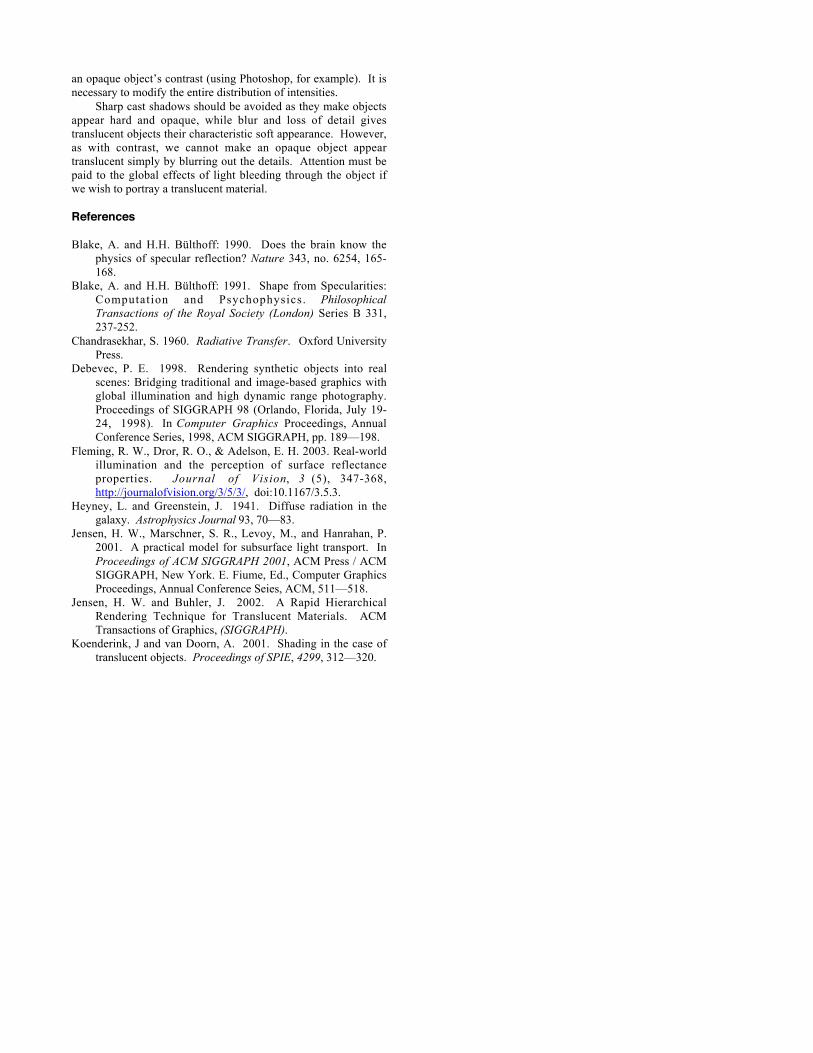
We have found, however, that blur is insufficient on its ownto produce a percept of translucency. If the intensity distributionis held roughly constant, adding blur by itself has little effect onperceived translucency (Figure 15). This makes sense given thatmany other factors can produce blur in images, including depthof field effects and shadow penumbras.
Figure 15. Effects of blur on perceived translucency.(a) Original version of Torus B. (b) Blurred versionof Torus B. (c) Blurriness in the more translucentTorus A. Note that the blur has almost no effect onthe apparent translucency of (b), although the blur isclearly visible in the close-up.
More generally, it is interesting to study the structure ofimages of translucent objects. The spatial organisation of lightsand darks in an image can be made visible by plotting the
isophotes (contours of equal luminance), as shown in Figure 16.Note the fact that the isophotes are closer together in Torus B thanin Torus A. This is related to the smoothness of Torus A, anotherway of conceiving of blur.
(a) Torus A (b) Torus B
Figure 16. Isophotes of Torus A and B. Note thebunching up around the edge of the shadow in TorusB.
It is important to note that spatial organization alone does nottell us whether an object is translucent or not. This isdemonstrated in Figure 17, which shows the photographicnegative of Torus A. The photographic negative has exactly thesame pattern of isophotes as its positive counterpart, and yet theimage does not appear translucent. This is important as itsuggests that the visual system attends to the direction in whichintensity is varying, and not just to the spatial layout of theintensity variations.
(a) Negative of Torus A (b) Isophotes
Figure 17. The photographic negative of Torus A hasthe same isophote pattern, but does not appeartranslucent
4. Conclusions
What makes wax, cheese or marble look translucent? Herewe have used a combination of psychophysics and image analysisto study some of the factors that influence perceived translucency.
To summarize our findings, let us conclude with somesuggestions for artists who wish to render translucent materials.
Translucent objects look most translucent when they areglossy and lit from behind. Glossiness also aids the perception ofshape, by recovering detail that is lost by the softening effects ofsubsurface scatter.
If we wish translucent objects to look ‘glowing’ and ‘warm’,colour saturation should be positively correlated with intensity.By contrast, if we wish them to look ‘icy’ or ‘dilute’, thecorrelation should be negative.
Translucent objects should be lower contrast than opaqueones. However, the relationship between translucent and opaqueversions of an object is generally non-linear. Thus, to portray atranslucent object realistically, it is not sufficient simply to reduce
(a)
(b)
(c)
an opaque object’s contrast (using Photoshop, for example). It isnecessary to modify the entire distribution of intensities.
Sharp cast shadows should be avoided as they make objectsappear hard and opaque, while blur and loss of detail givestranslucent objects their characteristic soft appearance. However,as with contrast, we cannot make an opaque object appeartranslucent simply by blurring out the details. Attention must bepaid to the global effects of light bleeding through the object ifwe wish to portray a translucent material.
References
Blake, A. and H.H. Bülthoff: 1990. Does the brain know thephysics of specular reflection? Nature 343, no. 6254, 165-168.
Blake, A. and H.H. Bülthoff: 1991. Shape from Specularities:Computation and Psychophysics. PhilosophicalTransactions of the Royal Society (London) Series B 331,237-252.
Chandrasekhar, S. 1960. Radiative Transfer. Oxford UniversityPress.
Debevec, P. E. 1998. Rendering synthetic objects into realscenes: Bridging traditional and image-based graphics withglobal illumination and high dynamic range photography.Proceedings of SIGGRAPH 98 (Orlando, Florida, July 19-24, 1998). In Computer Graphics Proceedings, AnnualConference Series, 1998, ACM SIGGRAPH, pp. 189—198.
Fleming, R. W., Dror, R. O., & Adelson, E. H. 2003. Real-worldillumination and the perception of surface reflectanceproperties. Journal of Vision, 3 (5), 347-368,http://journalofvision.org/3/5/3/, doi:10.1167/3.5.3.
Heyney, L. and Greenstein, J. 1941. Diffuse radiation in thegalaxy. Astrophysics Journal 93, 70—83.
Jensen, H. W., Marschner, S. R., Levoy, M., and Hanrahan, P.2001. A practical model for subsurface light transport. InProceedings of ACM SIGGRAPH 2001, ACM Press / ACMSIGGRAPH, New York. E. Fiume, Ed., Computer GraphicsProceedings, Annual Conference Seies, ACM, 511—518.
Jensen, H. W. and Buhler, J. 2002. A Rapid HierarchicalRendering Technique for Translucent Materials. ACMTransactions of Graphics, (SIGGRAPH).
Koenderink, J and van Doorn, A. 2001. Shading in the case oftranslucent objects. Proceedings of SPIE, 4299, 312—320.