pepsi-cola high visibility...
TRANSCRIPT

Pepsi-Cola High Visibility Vender For HT2 Venders Produced Beginning Production Run 6730BZ For HT3 Venders Produced Beginning Production Run 6757DZ For HT3 Tier 1 Energy Star Venders Produced Beginning Production Run 6978CC
Manufactured by
Dixie-Narco, Inc. P.O. Drawer 719 Williston, SC 29853-0719 888-353-9722 803-266-0700 fax: 803-266-4747 Visit us on the web: www.dixienarco.com
803,903,120.21

1
Table of Contents GENERAL INFORMATION
Application......................................................................................................................................................... 3 Vender Safety Precautions............................................................................................................................. 3 Product Identification....................................................................................................................................... 3 Physical Characteristics .................................................................................................................................. 3
A INSTALLATION & SETUP Unpacking the Vender..................................................................................................................................... 4 Electric Power Requirements......................................................................................................................... 4 Ground the Vender........................................................................................................................................... 4 Pepsi Electronic Door Lock........................................................................................................................4 - 5 Placing the Vender on Location..................................................................................................................... 5 Level the Vender .............................................................................................................................................. 5 Space the Vender............................................................................................................................................. 5 Coin Changers and Other Accessories ........................................................................................................ 6 Loading the Change Tubes ............................................................................................................................ 6 Loading Product................................................................................................................................................ 6 Initial Loading.................................................................................................................................................... 6
B PROGRAMMING
Historical Data................................................................................................................................................... 7 Interval Data – Resettable Data..................................................................................................................... 8 Set Price ............................................................................................................................................................ 8 Cash Settings.................................................................................................................................................... 8 User Menu...............................................................................................................................................10 - 17 Diagnostics Menu..................................................................................................................................17 – 18 Quick Reference Prompts .............................................................................................................................19 Default Space-To-Sales Setting...................................................................................................................20 Set Vender Type.............................................................................................................................................20
C GENERAL MAINTENANCE Power...............................................................................................................................................................21 Cleaning...........................................................................................................................................................21 Refrigeration Condenser...............................................................................................................................21 Coin Acceptor..................................................................................................................................................21 Lubricating the Vender..................................................................................................................................21 EPROM Replacement...........................................................................................................................22 - 24
D MAJOR COMPONENT DESCRIPTION Electrical ..........................................................................................................................................................24 Refrigeration....................................................................................................................................................24 HT2 Universal Controller...............................................................................................................................25 HT2 Machine Controller................................................................................................................................26 HT3 Control Board.........................................................................................................................................27
E TROUBLESHOOTING FLOWCHARTS All Coins are Rejected...................................................................................................................................28 All Bills are Rejected......................................................................................................................................29 Incorrect Change Dispensed........................................................................................................................30 Selection Will Not Vend.................................................................................................................................31 Ice / Frost on Evaporator...............................................................................................................................32 Compressor Runs Continuously..................................................................................................................32 Compressor Will Not Start ............................................................................................................................33 Machine Not Cooling......................................................................................................................................34 Can’t Enter the Menu or Diagnostics ..........................................................................................................35 Lights Are Not On ...........................................................................................................................................36 One or More Motors Run When Main Door is Closed..............................................................................37 Sold Out Switch..............................................................................................................................................38 The Display is Dead.......................................................................................................................................39 Can’t Read the Display..................................................................................................................................40

2
Table of Contents
F WIRING DIAGRAMS AND SCHEMATICS Figure 1 – HT2 Wiring Diagram ..................................................................................................................41 Figure 2 – HT3 Wiring Diagram ...................................................................................................................42 Figure 3 – Compressor Wiring Diagram .....................................................................................................43 Figure 4 – HT3 Choke / Relay Plate Assy. ...............................................................................................44 Figure 5 – HT2 Schaffner Fitter / Relay Plate Assy. .................................................................................45
G PARTS LIST
MAIN DOOR EXTERIOR ......................................................................................................................46 - 47 MAIN DOOR INTERIOR (A) .................................................................................................................48 - 49 MAIN DOOR INTERIOR (B) .................................................................................................................50 - 51 SELECT PANEL.....................................................................................................................................52 - 53 T8 LIGHTING..........................................................................................................................................54 - 55 ELECTRONIC COMPONENTS ...........................................................................................................56 - 57 INNER DOOR .........................................................................................................................................58 - 59 HARNESSING........................................................................................................................................60 - 63 CABINET AND VEND MECHANISM (SECTION ONE)...................................................................64 - 65 CABINET AND VEND MECHANISM (SECTION TWO) ..................................................................66 - 68 CABINET AND VEND MECHANISM (SECTION THREE)..............................................................69 - 71 CABINET INTERIOR .............................................................................................................................72 - 73 HINGES AND ROLLER ASSY.............................................................................................................74 - 75 REFRIGERATION SYSTEM (SECTION ONE).................................................................................76 - 77 REFRIGERATION SYSTEM (SECTION TWO) ................................................................................78 - 79 MISCELLANEOUS LABELS ........................................................................................................................80 SIGNS/DECALS/FLAVOR CARDS.............................................................................................................81 SCREWS & NUTS .................................................................................................................................82 - 83 WASHERS, BOLTS, & MISC. HARDWARE......................................................................................84 - 86

GENERAL INFORMATION
3
APPLICATION This manual applies to Pepsi-Cola High Visibility Venders (HVV), beginning with HT2 production run 6730BZ and HT3 production run 6757DZ. HVV venders that were manufactured prior to production run 6730BZ have significant differences in programming and parts content from previous versions. The earlier versions were manufactured in production runs 6664DY, 6672DY, and 6698BZ. To order parts, or for information pertaining to these earlier versions, please contact Dixie-Narco.
VENDER SAFETY PRECAUTIONS Please read this manual in its entirety. This service information is intended to be used by a qualified service technician, who is familiar with proper and safe procedures to be followed when repairing, replacing, or adjusting any Dixie-Narco vender components. All repairs should be performed by a qualified service technician who is equipped with the proper tools and replacement components, using genuine Dixie-Narco factory parts.
REPAIRS AND/OR SERVICING ATTEMPTED BY UNQUALIFIED PERSONS CAN RESULT IN HAZARDS DEVELOPING DUE TO IMPROPER ASSEMBLY OR ADJUSTMENTS WHILE PERFORMING SUCH REPAIRS. PERSONS NOT HAVING A PROPER BACKGROUND MAY SUBJECT THEMSELVES TO THE RISK OF INJURY OR ELECTRICAL SHOCK WHICH CAN BE SERIOUS OR EVEN FATAL.
PRODUCT IDENTIFICATION First production of HT2 was June 2001. First production of HT3 was December 2001. The production date of Dixie-Narco products is determined by the date code incorporated in the serial number. The vender serial number takes the form xxxx-yyyyzz. The last 4 digits (yyyy) identify the specific vender. The first 4 digits (xxxx) identify the manufacturing run that the vender was built in. The last two alpha characters (zz) identify the quarter and the year the vender was built. The first alpha-character identifies the quarter.
A = 1st quarter B = 2nd quarter C = 3rd quarter D = 4th quarter
The second alpha-character identifies the year:
Y = 2000 Z = 2001 A = 2002 B = 2003 C = 2004 D = 2005
PHYSICAL CHARACTERISTICS
276E 501E 600E
HEIGHT 72.5” 72.5” 79”
WIDTH 28” 37.5” 37.5”
DEPTH 36.0” 36.0” 36.0”
DEPTH WITH VALIDATOR
36.0” 36.0” 36.0”
SHIPPING WEIGHT 687 lbs. 833 lbs. 891 lbs.

INSTALLATION & SETUP
4
The Dixie-Narco Pepsi-Cola High Visibility Vender is designed utilizing the latest technology.
UNPACKING THE VENDERS Remove the stretch wrap and top cover from the vender. Product cards are installed in the select buttons.
DO NOT STORE THE VENDER OUTSIDE WITH THE STRETCH WRAP ON. THIS COULD CAUSE THE STRETCH WRAP TO BOND TO THE VENDER’S SURFACE, WHICH COULD DAMAGE THE FINISH.
Remove the shipping boards from the bottom of the vender. The shipping boards are attached by the leveling legs. To avoid unnecessary damage to the leveling legs or base, remove the shipping boards by using a 1½” “socket type” wrench to unscrew the leveling legs. Be sure to replace the legs after removing the shipping boards.
ELECTRIC POWER NEEDED Refer to the cabinet serial number plate to determine the proper voltage and frequency the machine requires (domestically this requirement is 115 Volts, 60 Hertz). The cabinet serial plate also indicates the Ampere rating of the vender. Single phase, alternating current is required. The vender must be plugged into a properly rated circuit with its own circuit protection (fuse/circuit breaker). DO NOT USE AN EXTENSION CORD.
GROUND THE VENDER The vender is equipped with a three-wire power supply cord and MUST be plugged in a properly grounded outlet. DO NOT REMOVE THE GROUND PIN OR IN ANY WAY BYPASS THE GROUND OF THE VENDER. If the outlet will not accept the power cord plug, contact an electrician to install a proper AC outlet.
FAILURE TO COMPLY WITH THESE INSTRUCTIONS MAY SUBJECT THE USER TO THE RISK OF INJURY OR ELECTRICAL SHOCK WHICH CAN BE SERIOUS OR FATAL.
PEPSI ELECTRONIC DOOR LOCK The electronic lock provided in the vender consists of a door mounted, motor driven bayonet (shaft) system, a cabinet mounted nut receptacle switch system, an infrared controlled CPU, and a remote control key (FOB). The design is modular and allows for easy field service. The electronic remote key (FOB) features a rolling code system which cannot be decoded if it is lost or stolen. After the vender has been unlocked, a new key can be programmed into it any number of times. If a key is lost or stolen, it is recommended you change the lock code in the field as soon as possible. Changing the lock code requires a new key and pressing the PROGRAM button on the lock inside the vender. The lock does not need to be changed for re-keying.
Important: For security reasons all Electronic Door Lock Venders are shipped less keys. Customers will need to contact the Electronic Door Lock manufacturer to order keys.
A power bypass connector, located in the product delivery port, allows auxiliary power to be applied via a battery pack to the electronic lock in the event that power is not available or there has been a failure of the internal power supply. In the event of an emergency, battery power is applied to the connector and the door can be opened and closed using the FOB. The electronics uses an infrared transmission system, which functions similar to a television remote control. The transmission signal is line-of-sight, which requires you to aim the remote at a specific place at close range to prevent the accidental opening of several venders at the same time.

GENERAL MAINTENANCE
5
TO OPEN THE PEPSI ELECTRONIC DOOR LOCK:
1. Plug the vender into a properly powered outlet.
2. Hold the key FOB 0 to 3 inches to the right side of select button #10 and press the button on the key FOB. Note: The wide end of the FOB should
face the door. 3. The lock will begin releasing the door. The
display will indicate Door opening. After the motor has stopped running, you can pull the door open. The display will indicate: Door unlocked.
TO CLOSE THE PEPSI ELECTRONIC DOOR LOCK: CAUTION: DO NOT SLAM THE DOOR CLOSED. Slamming the door closed can damage the electronic locking device.
1. Push the door to the cabinet until the lock motor starts. The display will indicate: Door closing.
2. Continue to push the door for approximately 2 to 3 seconds after the lock motor starts. The lock will pull the door closed tightly.
3. When the lock motor stops the door will be locked and the display will indicate: Door locked. Before leaving the vender, ensure that the door is locked.
The electronic door lock assembly is supplied by Tri Teq Lock and Security. Dixie-Narco, Inc. does not carry parts for the Tri Teq Electronic Door Lock. For parts and assistance, please contact:
Tri Teq 701 Gullo Elk Grove Village, IL 60007 Tel: 847-640-7002 Fax: 847-640-7008 Email: [email protected]
PLACING THE VENDER ON LOCATION !! CAUTION !!
DO NOT TRANSPORT THE VENDER TO OR FROM THE LOCATION LOADED WITH PRODUCT. DAMAGE TO THE VENDER MAY RESULT.
The vender must be located on a solid, flat, and level surface. The vender must be positioned close enough to an electrical outlet that an extension cord is not required. If the machine will be subject to user misuse or vandalism, it is recommended that the vender be secured to the floor or wall as described in Dixie-Narco Technical Bulletin 344. Call the Dixie-Narco Technical Service Department or your Dixie-Narco Representative for assistance.
LEVEL THE VENDER When the vender is level, the door can be opened to any position and it will not move by itself. Open the door to several different positions before deciding the vender is level. A carpenter’s level will help verify the machine is level. Make sure that all leveling legs are in contact with the floor. If you cannot level the vender in its current location, select another location. DO NOT place any objects under the machine.
DANGER
THE VENDE R MUST BE PROPERLY LOCATED AND LEVELED. IF THE MACHINE WILL BE SUBJECT TO USER MISUSE OR VANDALISM IT IS RECOMMENDED THAT THE VENDER BE SECURED TO THE FLOOR OR WALL AS DESCRIBED IN DIXIE-NARCO TECHNICAL BULLETIN 344 TO MINI MIZE THE RISK OF INJURY OR DEATH FROM TIPPING.. CALL THE DIXIE-NARCO TECHNICAL SERVICE DEPARTMENT OR YOUR DIXIE-NARCO REPRESENTATIVE FOR ASSISTANCE.
SPACE THE VENDER Do not block the rear of the vender. Keep the vender 4 inches (10 mm) from the wall to ensure adequate airflow to the condenser and compressor. At the front of the vender, make sure that nothing obstructs the air intake at the bottom of the main door. At the rear of the vender, make sure nothing obstructs the air exhaust at the bottom of the cabinet.

GENERAL MAINTENANCE
6
COIN CHANGERS & OTHER ACCESSORIES The vender must have an MDB coin changer installed and can have an MDB bill acceptor installed. If the MDB coin changer and other MDB accessories are not factory installed, refer to the instructions received from the manufacturer of the MDB coin changer and other MDB accessories for proper set-up and installation. The vender will support the following MDB coin changers:
Multi-Drop Coin Mech (Domestic) Coinco 9302GX Coinco USQ G700 Series Conlux USLZ-101 Conlux CCM5G Mars 4510 Mars 6512
The vender will support the following MDB bill validators:
Multi-Drop Bill Validators (Domestic) Coinco BA30B, BA50, MAG30, MAG50 Mars VN2512, VN2502, VN2312 Conlux NBM-3120, NBU-2111-12 Ardac 5500 Series
The vender will support the following MDB card readers:
Debitek Fage VMC LTD AT&T Danyl Schlumberger Diebold
LOADING CHANGE TUBES Open the main door and enter the “Fill Coin Mech” mode in the “CASH SETTINGS” sub-menu in Programming (see Section B – Programming). Load the coin mechanism with coins by inserting coins in the coin mech’s separator. The display will show the total value of coins as they are inserted. Note: A low coin level in the coin tubes will
interfere with operation of the bill validator. For additional information about coin mechanisms, refer to the specific manufacturer’s instructions.
Loading Product The Pepsi-Cola High Visibility Vender is designed to vend a wide range of cans, glass, and plastic beverage containers in sizes from 12 oz. to 24 oz.
All Pepsi-Cola High Visibility Venders are shipped ready to vend 20 oz. Pepsi Quick Slam (Swirl) PET bottles. To vend an alternative package in the Pepsi-Cola High Visibility Vender, contact a Dixie-Narco Factory Service Representative or refer to the proper Technical Bulletin for shimming and set-up information.
INITIAL LOADING To ensure proper loading, the wide column oscillator must be in the extreme left or right position. When loading the wide column, the first row of bottles should be loaded on the bottom bar of the oscillator. The second row of bottles must be loaded on the top bar of the oscillator. Always load complete rows; do not load only to the back or only to the front of the column. The narrow column rotors must be in the “cup” position to receive the first row of bottles. When loading narrow columns, lay the rows of bottles in the column until the column is full. DO NOT fill the columns to the top of the cabinet. Because the bottle stack will move up and down in the column during the vend cycle, allow about 2 inches at the top of the column. Correct loading will prevent service calls and ensure proper vending. After loading the vender for the first time, ensure the vender is loaded and working properly by test vending each selection with money until the first bottle is delivered. NOTE: To ensure proper airflow through the
evaporator, DO NOT place bottles (or other foreign) objects in the bottom of the tank.
SERVICE NOTE Battery Backup The Universal Control Board is equipped with a battery backup which is used to retain information programmed in the system (pricing, time, date, etc.) in case of power interruptions or any time the main power is off. When the vender is shipped, the battery is connected and memory is being maintained. Disconnect the battery if the vender will be stored for a long period of time. The following steps will guide you through this procedure. Ø Remove power from the vender by unplugging
the main power cord from the wall receptacle.
Ø Locate the HT2 Universal Control Board or HT3 Controller on the main door. Remove the battery from its holder (B1).

GENERAL MAINTENANCE
7
PEPSI-COLA HVV PROGRAMMING METHOD
June 2001 The controller has two modes of operation: NORMAL and SERVICE. NORMAL MODE: In Normal Mode, on power up display will show software installed in vender, then change to Ice Cold Drink message, Sold Out, Credit Value, or decimal point. If decimal is flashing, this indicates an error or problem recognized in the vender. When money is inserted, the display indicates the total amount of the deposit. The select buttons are used to select the product. In normal mode you may access an external menu for reading historical sales total, product total, product total by selection, and sales by price totals.
SERVICE MODE: The Service Mode is entered when the vender door is open and the service switch is pressed. The display will show a list of error codes for errors that have occurred since the door was last opened. "Jammed Column #” is a vend mechanism jammed, "Select Switch #" is a select switch problem, “Refrigeration” is a refrigeration or temp sensor problem, and “Door Switch” is a door switch open problem. To acknowledge an error, press any select button, at this time you will enter the menu. The display will show "Historical Data" at this time. Some of the menu items have sub-menus. To move through the menus and sub-menus follow these instructions. To:
MOVE THROUGH MENU: Press select buttons 1 & 2 simultaneously to scroll down through the menu. While scrolling down through menu, release, press select buttons 1 & 2 simultaneously to scroll up through menu.
ENTER SUB -MENU: Press and hold select button 1 to enter a sub-menu. EXIT SUB-MENU: With "Return" on display, press and hold select button 1 to exit a sub-
menu. EXIT SERVICE MODE: Closing the inner door or a five-minute inactivity time-out will exit the service mode.
FRONT PANEL PROGRAMMING SERVICE MENU
Historical Data This function shows the user the vender accounting over the life of the vender. Use the following select buttons to view the total sales in dollars, total number of vends and the total number of vends for each selection. Press Select Button 1: Shows the historical total cash sales for the life of the vender. Press Select Button 2: Shows the historical total number of vends. Press Select Button 3: Shows the historical number of vends by selection. Each selection automatically scrolls
across the display. Press & hold select buttons 1 & 2 simultaneously to move to the next item on the menu.
Side-By-Side
GENERAL MAINTENANCE
8
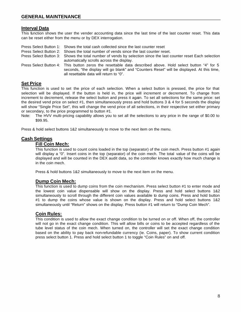
Interval Data This function shows the user the vender accounting data since the last time of the last counter reset. This data can be reset either from the menu or by DEX interrogation. Press Select Button 1: Shows the total cash collected since the last counter reset Press Select Button 2: Shows the total number of vends since the last counter reset. Press Select Button 3: Shows the total number of vends by selection since the last counter reset Each selection
automatically scrolls across the display. Press Select Button 4: This button zeros the resettable data described above. Hold select button “4” for 5
seconds, “the display will go blank” and “Counters Reset” will be displayed. At this time, all resettable data will return to “0”.
Set Price This function is used to set the price of each selection. When a select button is pressed, the price for that selection will be displayed. If the button is held in, the price will increment or decrement. To change from increment to decrement, release the select button and press it again. To set all selections for the same price: set the desired vend price on select #1, then simultaneously press and hold buttons 3 & 4 for 5 seconds the display will show “Single Price Set”, this will change the vend price of all selections, in their respective set either primary or secondary, to the price programmed to button #1. Note: The HVV multi-pricing capability allows you to set all the selections to any price in the range of $0.00 to
$99.95. Press & hold select buttons 1&2 simultaneously to move to the next item on the menu. Cash Settings
Fill Coin Mech: This function is used to count coins loaded in the top (separator) of the coin mech. Press button #1 again will display a “0”. Insert coins in the top (separator) of the coin mech. The total value of the coins will be displayed and will be counted in the DEX audit data, so the controller knows exactly how much change is in the coin mech. Press & hold buttons 1&2 simultaneously to move to the next item on the menu. Dump Coin Mech: This function is used to dump coins from the coin mechanism. Press select button #1 to enter mode and the lowest coin value dispensable will show on the display. Press and hold select buttons 1&2 simultaneously to scroll through the different coin values available to dump coins. Press and hold button #1 to dump the coins whose value is shown on the display. Press and hold select buttons 1&2 simultaneously until “Return” shows on the display. Press button #1 will return to “Dump Coin Mech”. Coin Rules: This condition is used to allow the exact change condition to be turned on or off. When off, the controller will not go in the exact change condition. This will allow bills or coins to be accepted regardless of the tube level status of the coin mech. When turned on, the controller will set the exact change condition based on the ability to pay back non-refundable currency (ie. Coins, paper). To show current condition press select button 1. Press and hold select button 1 to toggle “Coin Rules” on and off.

GENERAL MAINTENANCE
9
Escrow: This function supports 4 (four) escrow options. To show the current condition, press select button 1 will enter mode and show current escrow setting. Press and hold select button 1 will scroll through the available Escrow options and set the escrow mode to setting displayed when the select button1 is released.
Price 1
This escrow condition is forced vend option 1 (“escrow to price”). All dollar bills will be stacked. No cancel sale is allowed once minimum vend price is met or exceeded.
Price 2 This escrow condition is forced vend option 2 (“escrow no cancel”) with all bills stacked, and no cancel sale allowed unless the vender is in exact change and the maximum vend price is exceeded. Note: Any money entered below the vend price cannot be returned.
Select 4 This escrow condition is “escrow to select” with all the dollar bills being stacked. Cancel sale will return the deposit from the coin changer (i.e.4 quarters).
Select 1 This escrow condition is “escrow to select dollar bills” with the last dollar bill that meets or exceeds maximum vend price being escrowed in the validator. Cancel sale will return the held dollar bill and any amount over $1 will be returned from the coin changer.
Press & hold select buttons 1 & 2 simultaneously to move to the next item on the menu.
Multi Vend: This function, when turned on, allows credit to be retained after a vend so the customer can vend from another selection. (i.e..50 vend price, put in $1.00, push a select button and vends, .50 still shows on the display, push a second select button and vends). Credit is cancelled after 5 minutes of inactivity. There is unlimited acceptance. If a customer wants their credit (money) back, the coin return lever must be pressed. To show the current “Multi Vend” condition, press select button 1 and the display will show the current setting. Press and hold button 1 to toggle Multi Vend from on and off. Press and hold select buttons 1&2 simultaneously to move to “Return”. Return: Press and hold button 1 to move to “Cash Settings”.

GENERAL MAINTENANCE
10
User Menu: This function is used to configure the vender to operate in a fashion best suited for the vender location. To move to “Diagnostics”, press & hold select buttons 1&2 simultaneously, to enter the User Menu sub-menus press select button1. The following are sub-menus of the User Menu: Space To Sales, Time, Language, Electronic Counter, Limited Access, Secondary Price, Light, Refrigeration, Free Vend, Override, Sales Message, Recharge, and Return.
Space To Sales To view the space to sales condition, press select button 1 and display will show “Selection 1”. Alternating with columns assigned to that select button. Press select buttons 1&2 simultaneously to scroll through the available select buttons to view columns assigned and “Return”. To change space to sales:
Press select button 1 at the “Selection #” prompt and “Column ## #” (column edit routine) will be displayed, where the ## is the first column to added or deleted to the select button and the third # is “0” for not assigned or “1” for assigned to that selection. Press select button 1 with “Column ## #” on the display to toggle between “Column ## 0” and “Column ## 1”. With the setting you wish to use showing on the display, press select buttons 1 & 2 to scroll to next selection to add/delete columns or “Return”. Press select button 1 at the “Return” prompt will return to “Space to Sales”. Note: You must be in the “Selection” prompts to get to the “Return” mode that scrolls to “Space To Sales”. Press & hold select buttons 1 & 2 simultaneously to move to the next item on the menu.
Time This function is used to set the year, month, day, hour/minute (military 24 hour clock), and daylight savings time. Press select button 1 and “Year” will show on display. Press select buttons 1 and 2 simultaneously to scroll through all “Time” sub-menus.
“Year”- Year Setting (00 to 99) Press select button 1 the current year setting will show on display. Press and hold select button 1 to increment the year setting (2000 to 2099). Release select button 1 and press and hold again will decrement the year setting. Release the select button with the display showing the year you wish to use and display will return to “Year”. Press select buttons 1 & 2 simultaneously to scroll to “Month”.
“Month” - Month Setting (01 to 12)
Press select button 1 and the current 2-digit month setting will show on display. Press and hold select button 1 to scroll through the month settings. (01-Jan. to 12-Dec.). Release the select button with the display showing the month you wish to use and display will return to “Month”. Press select buttons 1 & 2 simultaneously to scroll to “Day”.
“Day” - Day of Month Setting (1 to 31)
Press select button 1 and the current 2-digit day of month setting will show on display. Press and hold select button 1 to scroll through the day of month settings (1 to 31). Release select button 1 and press and hold again will decrement the day of month setting. Release the select button with the display showing the day of month setting you wish to use and display will return to “Day”. Press select buttons 1 & 2 simultaneously to scroll to “Hour/Minute”.

GENERAL MAINTENANCE
11
“Hour/Minute” - Hour and Minute Setting (0000 to 2359)
Press select button 1 and the current 4-digit hour and minute setting will be displayed (24 hour). Press and hold select button 1: Set Hours Press and hold select button 2: Set Minutes Press select buttons 1&2 simultaneously to move to the next item in the menu.
Daylight Savings Time
Press select button 1 and the current setting will show on the display. Press and hold select button 1 to scroll through the “Daylight Savings Time” options listed: “American” – North American rules – Set forward 1 hour at 2:00 am on the first Sunday in April; Set backward 1 hour at 2:00 am on the last Sunday in October. “European” – European rules – Set forward 1 hour at 1:00 am on the last Sunday in March; Set backward 1 hour at 1:00 am on the last Sunday in October. “Australian” – Australian rules – Set forward 1 hour at 1:00 am on the first Sunday in October; Set backward 1 hour at 1:00 am on the last Sunday in March. “Off” – Off Rules – Daylight savings time change will not be made. Release the select button with the display showing the “Daylight Savings Time” setting you wish to use and display will return to “Daylight Savings Time”. Press and hold select buttons 1&2 simultaneously to move to “Return”. Press select button 1 to move to “Time”
Language This function is used to set the language that will be used for display messages. To display the current language selected, press select button 1. To change the language selected, press & hold select button 1 to scroll through the language menu. Once the desired language is shown on the display, release the button. The display will then return to "Language".
English Spanish French Slovene German Finnish Italian Norwegian Portuguese
Press and hold select buttons 1 & 2 simultaneously to move to the next item on the menu.
Electronic Counter This function is used to show historical cash sales, historical total vends, historical product counts by selection, and historical product counts that have occurred for prices being used from outside the vender. Press select button 1 to view the current four (4) button code. To view the data the four button code must be entered. Once entered the listed menus are available from the front of the vender:
Press select button 1: Show historical cash sales. Press select button 2: Show historical total vends. Press select button 3: Show historical product counts by selection. Press select button 4: Show list of prices and historical product counts that have occurred for
those prices. Press select button 5: Returns to sales idle mode (normal vender operation).

GENERAL MAINTENANCE
12
To change "Electronic Counter" four button code: At "Electronic Counter" press select button 1, "4231" (representing current four button code) will show on display. Press and hold select button 1 until the far left digit will change to *, indicating it can be changed. Press the select button which is desired for the code. The next digit will start blinking; press the select button which is desired for the code. Continue this process until all 4 digits are set. Note: The four-button code must use select buttons 1 through 9 only. Note: There is a five (5) minute time-out that will return the vender to normal vending mode. Press & hold select buttons 1 & 2 simultaneously to move to the next item on the menu.
Limited Access This function is used to program the vender to use the Limited Access Features. To move to Secondary Price Menu, press & hold select buttons 1 & 2 simultaneously, to enter the sub-menu press select button 1. The following are sub-menus of Limited Access Menu: "Selects", "Days”, “Start 1”, “Stop 1”, “Start 2”, “Stop 2”, and “Return”.
Selects This function is used to set selection(s), which, will be limited during certain periods of the day. To view the selection setting condition, press select button 1. The display will show "Selection 01 - # where # is a “0” OR “1” depending on whether the selection is enabled (1) or disabled (0). Press and hold select button 1 to toggle between “0” & “1. Press select buttons 1 & 2 simultaneously to scroll through all available select buttons, “NONE”, “ALL”, and “Return”. Pressing select button 1 when “ALL” or “NONE” are displayed will cause the display to flash momentarily. Press select button 1 at the “Return” prompt returns to “Selects”. Press & hold select buttons 1 & 2 simultaneously to move to the next item on the menu. Days This function is used to set the days of the week to be affected by limited access. Day of Week: Sunday Wednesday Saturday Return
Monday Thursday All Days Tuesday Friday no days
Press select button 1 and "Monday#" will show on the display, where # is “0” (disable) or “1” (enable). Press and hold select button 1 to toggle between “0” and “1”. Release the select button with the display showing the setting you wish to use. Press select buttons 1 & 2 simultaneously to scroll through all available days, “All Days”, “not found”, and “Return”. Press select button 1 at the “Return” prompt returns to “Days”. Press & hold select buttons 1 & 2 simultaneously to move to the next item on the menu.
Start 1 This function is used to set the hours and minutes to start period 1 limited access. Press select button 1 and the current four-digit hour and minute setting will to be displayed (24 hour). Press & hold select button 1: Set Hours Press & hold select button 2: Set Minutes Press select buttons 1 & 2 simultaneously to move to the next item in the menu. Stop 1 This function is used to set the hours and minutes to stop period 1 limited access. Press select button 1 and current four-digit hour and minute will be displayed. (24 hour). Press & hold select button 1: Set Hours Press & hold select button 2: Set Minutes Press select buttons 1 & 2 simultaneously to move to the next item in the menu.

GENERAL MAINTENANCE
13
Start 2 This function is used to set the hours and minutes to start period 2 limited access. Press select button 1 and the current four-digit hour and minute setting will be displayed (24 hour). Press & hold select button 1: Set Hours Press & hold select button 2: Set Minutes Press select buttons 1 & 2 simultaneously to move to the next item in the menu. Stop 2 This function is used to set the hours and minutes to stop period 2 limited access. Press select button 1 and the current four-digit hour and minute setting will be displayed (24 hour). Press & hold select button 1: Set Hours Press & hold select button 2: Set Minutes Press select buttons 1 & 2 simultaneously to move to the next item in the menu. Return Press select button 1 to return to “Limited Access”. Press & hold select buttons 1 & 2 simultaneously to move to the next item on the menu.
Secondary Price This function is used to program a second price for each selection. To enter the sub-menu press select button 1. The following are sub-menus of Secondary Price Menu: “Price”, “Days”, “Start”, “Stop”, and “Return”. Press select button 1 at “Return” to return to “Secondary Price”.
Price This function is used to set the price of each selection. When a select button is pressed, the price For that selection will be displayed. If the button is held in, the price will increment or decrement. To change from increment to decrement, release the select button and press it again. Note: The HVV multi-pricing capability allows you to set all selections to any price in the range
of $0.00 to 99.95. Press & and hold select buttons 1 & 2 simultaneously to move to the next item on the menu.
Days This function is used to set the days of the week to be affected by secondary pricing. Day of Week: Sunday Wednesday Saturday Return
Monday Thursday All Days Tuesday Friday no days
Press select button 1 and “Monday #” will show on the display, where # is “0” (disable) or “1” (enable). Press and hold select button 1 to toggle between “0” and “1”. Release the select button with the display showing the setting you wish to use. Press select buttons 1 & 2 simultaneously to scroll through all available days, “All Days”, “not found”, and “Return”. Press select button 1 at the “Return” prompt returns to “Days”. Press & hold select buttons 1 & 2 simultaneously to move to the next item on the menu. Start This function is used to set the hours and minutes to start secondary pricing. Press select button 1 and the current four-digit hour and minute setting will be displayed. Press and hold select button 1 to change the hour setting, press button 2 to change the minute setting. Press select buttons 1 & 2 simultaneously to move to the next item in the menu.

GENERAL MAINTENANCE
14
Stop This function is used to set the hours and minutes to stop secondary pricing. Press select button 1 and the current four-digit hour and minute setting will be displayed. Press and hold select button 1 to change the hour setting, press button 2 to change the minute setting. Press select buttons 1 & 2 simultaneously to move to the next item in the menu. Return Press button 1 to scroll to Secondary Pricing Press buttons 1 & 2 to scroll to the next item in the menu
Environmental Controls This function is used to turn the lights and/or refrigeration off and on during certain periods of the day. Press select button 1 and the current setting will be displayed. Press and hold select button 1 to toggle on and off. With the display showing the setting you wish to use, after approximately 5 seconds display will return to “Environmental Controls” and you may scroll to next item on menu. Light This function is used to turn the lights off and on during certain periods of the day. Press select button 1 will enter “Days”.
Days This function is used to set the days of the week to turn lights on and off. Day of Week: Sunday Wednesday Saturday Return
Monday Thursday All Days Tuesday Friday no days
Press select button 1 and "Monday #" will show on the display, where # is “0” (disable) or “1” (enable). Press and hold select button 1 to toggle between “0” and “1”. Release the select button with the display showing the setting you wish to use. Press select buttons 1 & 2 simultaneously to scroll through all available days, “All Days”, “not found”, and “Return”. Press select button 1 at the “Return” prompt returns to “Days”. Press & hold select buttons 1 & 2 simultaneously to move to the next item on the menu.
Start This function is used to set the hours and minutes to start lighting routine.
Press select button 1 and the current four-digit hour and minute setting will be displayed. (24 hour). Press & hold select button 1: Set Hours Press & hold select button 2: Set Minutes Press select buttons 1 & 2 to scroll to start. Press select buttons 1 & 2 simultaneously to move to the next item on the menu. Stop This function is used to set the hours and minutes to stop lighting routine. Press select button 1 and the current four-digit hour and minute setting will be displayed. (24 hour) Press & hold select button 1: Set Hours Press & hold select button 2: Set Minutes Press select buttons 1 & 2 to scroll to stop. Press select buttons 1 & 2 simultaneously to move to the next item on the menu. Enable This function is used to allow the lighting routine to go in to affect. Press select button 1 and the current setting will be displayed (On or Off). Press and hold select button 1 to toggle between “On” and “Off”.

GENERAL MAINTENANCE
15
Release the select button showing the setting you wish to use and display will return to “Enable”. Press select buttons 1 & 2 to scroll to “Return”. Return Press select button 1 to return to “Light”. Press & hold select buttons 1 & 2 simultaneously to move to the next item on the menu.
Refrigeration This function is used to electronically control the refrigeration operations of the vender. Press select button 1 will enter “Temperature”.
Temperature (Default Temperature 350F/150C) This function is used to set the average product temperature for initial pull down and reload recovery. Press select button 1 and “tt.tx” will show on the display where x is F (Fahrenheit) or C (Celsius) and tt.t is the degrees. Press and hold select button 1 to increase or decrease the number by 1F or 0.5C. Release select button with the display showing the temperature you wish to use and display will return to “Temperature”. Press select buttons 1 & 2 to scroll to “Celsius or Fahrenheit”.
Celsius or Fahrenheit This function is used to set the degree reading to Fahrenheit (F) or Celsius (C). Press select button 1 and the current setting will show on the display. Press and hold select button 1 to toggle between F and C. Release the select button with the display showing the setting you wish to use and display will return to “Celsius or Fahrenheit”. Note – sales message and display must be turned on to display current temperature. Press select buttons 1 & 2 to scroll to “Display”. Display This function is used to enable the Temperature to be displayed following the “Ice Cold Drink” message. Press select button 1 and “Display” will show on the display. Press select button 1 and the current setting will be displayed (On or Off). Press and hold select button 1 to toggle between “On” and “Off”. Note – sales message and display must be turned on to display current temperature. Press & hold select buttons 1 & 2 simultaneously to move to the next item on the menu.
Days This function is used to set the days of the week to use Temperature Setting Routine.
Day of Week: Sunday Wednesday Saturday Return Monday Thursday All Days Tuesday Friday no days
Press select button 1 and “Monday #” will show on the display, where # is “0” (disable) or “1” (enable). Press and hold select button 1 to toggle between “0” and “1”. Release the select button with the display showing the setting you wish to use. Press select buttons 1 & 2 simultaneously to scroll through all available days, “All Days”, “not found”, and “Return”. Press select button 1 at the “Return” prompt returns to “Days”. Press & hold select buttons 1 & 2 simultaneously to move to the next item on the menu. Start
This function is used to set the hours and minutes for storage temperature to become active. Press select button 1 and the current four-digit hour and minute setting will be displayed (24 hour) Press & hold select button 1: Set Hours Press & hold select button 2: Set Minutes

GENERAL MAINTENANCE
16
Press select buttons 1 & 2 simultaneously to move to the next item on the menu. Stop This function is used to set the hours and minutes for storage temperature to become inactive. Press select button 1 and the current four-digit hour and minute setting will be displayed (24hour). Press & hold select button 1: Set Hours Press & hold select button 2: Set Minutes Press select buttons 1 & 2 simultaneously to move to the next item on the menu.
Storage Temperature (Default Temperature 600F/ 160C) This function is used to set the temperature for product storage. Press select button 1 and “tt.tx” will show on the display where x is F (Fahrenheit) or C (Celsius) and tt.t is the degrees. Press and hold select button 1 to increase or decrease the number by 1 F or 0.5 C. Release select button with the display showing the temperature you wish to use and display will return to “Storage Temperature” Press select buttons 1 and 2 simultaneously to scroll to “Storage Enabled”
Storage Enabled This function is used to enable the storage setting to go in affect. Press select button 1 and the current setting will be displayed (On or Off). Press and hold select button to toggle between ”On or Off”. Release the select button showing the setting you wish to use and display will return to “Storage Enabled” Press select buttons 1 & 2 to scroll to “Return” Press select button 1 at “Return” to scroll to “Refrigeration” Press select buttons 1 & 2 simultaneously to scroll to next item on the menu.
Free Vend This function is used to set the Free Vend option. Note: For free vend to become active a free vend switch must be connected to controller on free vend switch connector. Press select button 1 and “Enable” will show on Display.
Enable This function is used to allow the free vend to go in affect. Press select button 1 and the current setting will be displayed (On or Off). Press and hold select button 1 to toggle between “ On or Off”. Release the select button showing the setting you wish to use and the display will return to “Enable”. Press select buttons 1 & 2 to scroll to “Display”
Display This function is used to show the current number of free vends performed by the controller. Press select button 1 and “#” will show on the display where “#” is the number of free vends performed by the controller. Release the select button and display will return to “Display” Press select buttons 1 and 2 simultaneously to scroll to “Reset” Reset This function is used to reset number of free vends to zero. Press and hold select button 1 for 5 seconds to reset the number of free vends performed by the controller to zero. Release the select button and the display will return to “Reset”. Press select buttons 1 & 2 to scroll to “Return”. Return Press select button 1 to return to “Free Vend”. Press & hold select buttons 1 & 2 simultaneously to move to the next item on the menu.

GENERAL MAINTENANCE
17
Override This function is used to allow a key switch to override some of the settings stored for normal operations. When enabled and the override switch is in the closed position, the controller will override “Free Vend”, disable vending, disable currency acceptance, display will show “No Sales”, and lights will be off if Environmental Kit is installed. Vender will remain in this idle state until the override switch is in the open position. Press select button 1 and the display will show the current setting for 2 seconds (On or Off). Press and hold select button 1 to toggle between “On” – enabled and “Off” – disabled. Release the select button showing the setting you wish to use and display will return to “Override”. Press select buttons 1 & 2 to scroll to “Sales Message”. Sales Message This function is used to turn on the scrolling message “Ice Cold Drink”. Press select button 1 and the display will show the current setting (On or Off). Press and hold select button 1 to toggle between “ On or Off”. Release the select button showing the setting you wish to use and display will return to “Sales Message”. Press select buttons 1 & 2 simultaneously to scroll to “Recharge” Recharge This function is used to enable the recharge card setting routine. Press select button 1 and the display will show the current setting (On- recharge card enabled or Off- recharge card disabled). Press and hold select button 1 to toggle between “On and Off”. Release the select button showing the setting you wish to use and display will return to “Recharge”. Press select buttons 1 & 2 simultaneously to scroll “Return”
Return Press select button 1 to return to “User Menu”. Press & hold select buttons 1 & 2 simultaneously to move to the next item on the menu.
Diagnostics This function allows you to systematically diagnose problems related to the vender. To move to “Auto Test” press select buttons 1 & 2 simultaneously, to enter sub-menu press select button 1. The following are sub-menus of Diagnostics Menu: “Selection”, “Sold Out Empty Test”, “Sold Out Full Test”, “Motors”, “Coin mech”, “Note Acceptor”, “Display”, “Relay”, and “Return”.
Selection Press any select button, and the display will indicate the number of the select button pressed. Press & hold select buttons 1 & 2 simultaneously to the next item on the menu. Sold Out Empty Test Use this to test the sold-out switches if the vender is empty. Press select button 1 to display any sold out paddles that are not pressed, indicating that a column is empty. The display will automatically scroll through the columns that are sold out or display “none” if all columns have product. Press select button 1 to return to “Sold Out Empty Test”. Press & hold select buttons 1 & 2 simultaneously to move to the next item on the menu. Sold Out Full Test Use this to test the sold out switches if the vender is full. Press select button 1 to display any Sold Out Paddles that are pressed, indicating that the column is full. The display will scroll through the columns that have product or display “none” if all columns are sold out. Press select button 1 to return to “Sold Out Full Test”. Press & hold select buttons 1 & 2 simultaneously to move to the next item on the menu.

GENERAL MAINTENANCE
18
Motors Use this test to run any motor in the stack. Press select button 1and “Motor 1” will show on the display. Use the following select buttons to run this test. Press Select Buttons 1&2: Press until desired motor # to run or “Return” is shown on the display. Press Select Button 1: Press to run the selected motor. The display will show “Vending” and the
selected motor will run. Coin mech Use this test to check coin mech, coin chute, and the coin mech payout systems. Insert coins. The value of the coins will be reflected on the display. Press select button 2 will exit the test and return any coins inserted and return to “Coin mech”. Press select buttons 1 & 2 simultaneously to move to the next item on the menu. Note Acceptor Use this test to check note acceptor. Insert a bill. Bill will be held in escrow. Press select button 2 to stack the bill. Press select button 3 to return the bill. After the note is has been stacked or returned, the display will return to “Note Acceptor”. Press & hold select buttons simultaneously to move to the next item on the menu. Display Press select button 1 and the display will illuminate in a scrolling manner all available characters and return to “Display”. Press & hold select buttons 1 & 2 simultaneously to move to the next item on the menu. Relay
Compressor # This function allows you to test the relay electronic control of the compressor. CAUTION: Disconnect power to the compressor before testing the compressor relay.
Failure to disconnect power to the compressor before testing the relay could result in damage to the compressor.
Press select button 1 and the display will show “Compressor #”, where # is the state of the relay 0 = not activated or off; 1= activated or on. Press select button 1 to toggle the relay on and off. Press select buttons 1 & 2 simultaneously to move to “Fan”. Fan # This function allows you to test the relay electronic control of the evaporator fan. Press select button 1 and the display will show “Fan #” where # is state of the relay 0 = not activated or off; 1 = activated or on. Press select button 1 to toggle the relay on and off. Press select buttons 1 & 2 simultaneously to scroll to “Light”. Light # This function allows you to test the relay electronic control of the lights. Press select button 1 and the display will show “Light #”, where # is the state of the relay 0 = not activated or off; 1 = activated or on. Press select button 1 to toggle the relay on and off. Press select buttons 1 & 2 simultaneously to scroll to “Return”. Press select button 1 to return to “Relay”.
Return Press & hold select buttons 1 & 2 simultaneously to scroll to “Return”. Press select button 1 to return to “Diagnostics”. Press and hold select buttons 1 & 2 simultaneously to scroll to “Auto Test”.
Auto Test This function is used in Dixie- Narco’s manufacturing process and is not intended for use in the field. It’s purpose is a self-test routine to check the HVV components listed. For further details contact Dixie-Narco Factory Service. Press and hold select buttons 1 & 2 simultaneously to scroll to “Return”. Return Press & hold select buttons 1 & 2 simultaneously to scroll to “Return”. Press select button 1 to return to normal operation.

CONTROLLER PROGRAMMING
19
PEPSI HVV QUICK REFERENCE MENU PROMPTS Main Menu Sub-Menu Sub-Sub-Menu Main Menu Sub-Menu Sub-Sub-Menu
Historical Data User con't. Environmental Controls On/Off
Interval Data Light Days
Set Price Start
Cash Settings Fill Coin Mech Stop
Dump Coin Mech Enable
Coin Rules Return
Escrow Price 1 Refrigeration Temperature
Price 2 Celsius or Fahrenheit
Select 4 Display
Select 1 Days
Multi Vend Start
Return Stop
User Menu Space To Sales Storage Temperature
Time Year Storage Enable
Month Return
Day Free Vend Enable
Hour/Minute Display
Daylight Savings Time Reset
Return
Return Override
Language Sales Message
Electronic Counter Recharge
Limited Access Selects Return
Days Diagnostics Selection
Start 1 Sold Out Empty Test
Stop 1 Sold Out Full Test
Start 2 Motors
Stop 2 Coin mech
Return Note Acceptor
Secondary Price Price Display
Days Relay Compressor #
Start Fan #
Stop Light #
Return Return
Return
Auto test
Return
A. Press and hold select buttons 1 & 2 simultaneously to move through the menu from top to bottom.
B. Press select button 1 to move left/right or enter/exit in the menu, depending on the menu prompt on the display.

CONTROLLER PROGRAMMING
20
Setting The Vender Type When installing a service control board that has not been installed in a vender, the control board needs to set the vender type to recognize and perform proper space-to-sales options and vending operations. To set the vender type:
1. Remove power to the vender. 2. Remove the existing control board. 3. Install the new control board. 4. Power-up the vender and the display will
scroll “Set Model Number”. 5. Press button 1 and the machine will display
the model number available “DN501E-HV-12”.
6. Press buttons 1 and 2 simultaneously, this will allow the user to cycle through the available model numbers for that machine type (see list below). Once the desired model number is displayed “DN501E-HV-12” or ” DN600E-HV-12”, pressing button 1 will set this type.
Note: If the incorrect model number is set, the machine will not have the correct default space-to-sales arrangement. The user should power up the unit with the door open and press button 1 when the Model Number is displayed. The display will show “Set Model Number”. Follow steps 5 and 6 above. Only the Model Numbers that correspond to the number of columns in the machine will show. See list:
5 Column Venders DN300-5 6 Column Venders DN276-6 DN168-6 DN360-6 DN630T-6 DN522-6 7 Column Venders DN276E-7 DN276E-HV-6 DN276E-HV-5 8 Column Venders DN368-8 DN501T-8 DN440-8 DN600T-8 9 Column Venders DN501E-9 600E-10 DN600E-9 DN600E-HV-12 DN501E-HV-12 DN501E-HV-11 501E-10 DN600E-HV-11 10 Column Venders DN348-10 DN414-10
Factory Default Setting
Selection # Column #
1 1 2 1 3 2 4 3 5 4 6 4 7 5 8 6 9 7 10 8 11 9 12 9

GENERAL MAINTENANCE
21
The most important facets of proper vender care and maintenance are the electrical power supplied to it, leveling, and cleanliness of the machine and its components.
POWER The vender must be connected to a dedicated 120VAC, 15 Amp circuit (U.S. and Canada).
CAUTION: REMOVE POWER TO THE VENDER PRIOR TO CONNECTING / DISCONNECTING ANY ELECTRICAL COMPONENTS FOR TESTING OR REPLACEMENT.
CLEANING
DO NOT USE A WATER JET OR NOZZLE TO CLEAN THE VENDER
SIGN FACE
The polycarbonate sign face requires proper cleaning to prolong its service life. Periodically clean the sign as follows:
1. Rinse the sign with a soft cloth or sponge soaked in warm water.
2. If necessary, use a mild soap to loosen any dirt or grime. DO NOT SCRUB or use a brush or squeegee. Scrubbing may cause damage to signs with a clear ultraviolet resistant coating (prevents yellowing).
3. Repeat the above steps as necessary. To prevent spotting, dry the sign using a soft cloth.
CABINET
1. Wash the cabinet with a good detergent or soap mixed with warm water.
2. Wax the vender often with a good grade of automobile wax.
3. Any corrosion inside of the vender should be removed with a fine steel wool and the area should be painted with aluminum paint.
4. Repair any scratches on painted surfaces to prevent corrosion.
THE COMPRESSOR ELECTRICAL CIRCUIT IS ALWAYS LIVE WHEN THE PLUG IS CONNECTED TO AN ELECTRICAL OUTLET
REFRIGERATION CONDENSER • Check the condenser periodically for dirt or lint
build-up. • Remove build-up with a brush or vacuum, or
blow the dirt out of the condenser with compressed air and an approved safety nozzle.
• Ensure nothing obstructs the air intake at the bottom of the main door.
• Ensure nothing obstructs the air exhaust at the rear of the cabinet.
COIN ACCEPTOR • Follow the coin acceptor manufacturer’s
cleaning instructions.
LUBRICATING THE VENDER Time Component Lubricant Example
Every 6 months (or as needed) Every Year (or as needed)
Main Door 1. Lock Bolt & Nut
Retainer 2. Hinge Pivot Points
Inner Door
1. Hinge Pivot Points
Inner Door 1. Door Gasket
Mechanics Friend Mechanics Friend Mechanics Friend Petroleum Jelly
GENERAL MAINTENANCE
22
Single Board Controller (SBC) Software Update Procedure
This document describes how to update software on the Single Board Controller (SBC). Note: All existing software revisions, except software version 804,919,240.11, will automatically update the software revision 804,919,240.41 or higher upon installation. For SBC boards using 804,919,240.11 software menu programming is required to manually update the software. Important: EPROM’s containing software is sensitive to Electrostatic Discharge (ESD). Failure to handle the EPROM carefully could cause damage, which may result in a failed Single Board Controller (SBC). ALWAYS KEEP THE EPROM IN THE ESD TUBE. GROUND YOURSELF ON THE VENDER CABINET BEFORE REMOVING THE EPROM FROM THE ESD TUBE OR CONTROL BOARD. AN EPROM CAN BE USED TO PROGRAM MANY VENDERS, AS LONG AS CARE IS TAKEN NOT TO DAMMAGE THE EPROMS LEGS. ALWAYS TURN POWER OFF BEFORE REMOVING OR INSTALLING EPROMS IN THE CONTROL BOARD. Important Notes: Use the SBC programming manual to program a vender that has a Single Board Controller (SBC) installed. Resetting the machine’s model number is required when updating the space to sales default for Dr Pepper SL5 DN501E-10 machines only (software revisions 804,919,240.41C, 804,919,240.51 and higher). The model number reset will make the new space to sales default settings operational. The procedure to reset the model number is provided in section IV.
I. EPROM removal • Power down the Vender. Ground yourself on the vender cabinet before removing the
EPROM from the ESD tube or control board. • If the EPROM is present in the SBC, remove the existing EPROM from the SBC.
• Note: An EPROM does not need to be in the board after the SBC has been programmed. The EPROM can be used to reprogram other boards.
• Verify the pins of the new EPROM are not bent before installing in the EPROM socket. • Install the new EPROM in the EPROM socket. Ensure the EPROM is oriented correctly
with its reference marker (locator) in the same direction as the reference marker (locator) of the EPROM socket. Do not rely on the EPROM label for orientating the EPROM. See Figure 1.
II. Automatic Reprogramming (all software revisions except 804,919,240.11)
• Turn power on to Vender. When auto-updating, the display will remain blank while the red LED on the board blinks rapidly for 3-4 seconds. Verify the new software version is shown on the display. If the new software version (the software version of the newly installed EPROM) displays, the SBC software has been successfully updated. If not, verify the EPROM is seated properly, with the reference marker oriented correctly and follow instructions for manual update if updating from 804,919,240.11. If problems still exist, contact the Dixie-Narco Technical Service Department.

GENERAL MAINTENANCE
23
Note: To remove the EPROM after programming is complete turn power off, ground yourself on the vender cabinet before removing the EPROM, remove the EPROM, turn power on, test vender for proper operation.
III. Manual Reprogramming (all 804,919,240.11 or if an EPROM does not automatically reprogram the SBC)
• At power up, the current software version will be displayed. To manually program the control board with the new software, press the blue service switch on the SBC to enter the service menu. Advance to the “Auto Test” menu by holding buttons 1& 2 simultaneously. Enter Auto Test by pressing button 1, and advance to the “Reprogramming Microprocessor” submenu by holding buttons 1& 2 simultaneously.
• At the “Reprogramming Microprocessor” prompt, press button 1. “THIS OPERATION REPROGRAMS VENDOR” shows on the display. Press button 1 at this prompt. Next display will show “BUTTON 2 = REPROGRAM, BUTTON 3 = EXIT”.
• Press button 2 to reprogram vender with the new software. “Reprogramming Vendor…” displays while the red LED on the board blinks rapidly for 3-4 seconds. Verify the new software version, and previous settings return to the display. If the new software version (the software version of the newly installed EPROM) shows on the display, the SBC software has been successfully updated. Note: To remove the EPROM after programming is complete, remove power to the vender, ground yourself on the vender cabinet before removing the EPROM, remove the EPROM, while still grounded install a label on the microprocessor showing the revision of software that is installed in the SBC, power the vender back on and test for proper operation.
Figure 1
IV. Dr Pepper SL5 DN501E-10 machines model number resetting to update the space to sales (software revisions 804,919,240.41C, 804,919,240.51 and higher). This is needed due to number 1 and number 2 select buttons flavor specifications being permanent.
• The software revisions listed must be updated in the machine through either step II or III before the new space to sales changes will work.
• After the new software is updated, make sure the vending machine’s door is open. • Remove power to the machine, by unplugging it from the outlet or at the stack plug.. • Reapply power to the machine. • At power up the current software version and model number will scroll across display. • After the current model number is displayed, press select button 1. Then display will show
“MODL” for set model number.
Locators
Locators
240.41 Label on microprocessor to show what revision of software is in SBC if EPROM is removed after reprogramming.

GENERAL MAINTENANCE
24
• Release and press select button 1 to enter the set model number menu. The current model number will display. Note: this will say 501E-10. Press and hold select buttons 1 and 2 simultaneously to scroll through the available model numbers and back to 501E-10. Release when the model number you wish to use is displayed (501E-10).
• Display will show model number selected (501E-10). Press select button 1 to lock in the setting. After the model number is successfully reprogrammed, the new space to sales settings will be operational.
ELECTRICAL Transformer Provides 24 volt and 12 volt
power to the Machine Controller
Fuse (F1) 1.6 Amp Slo Blo Control Board Power (includes display and MDB Peripherals)
Fuse (F2) 6.0 Amp Fast Blo Vend Motor Power
Relay Potter & Brumfield T91P5D52-24 240VAC/20A -NO/10A-NC (Compressor, Light, Fan)
Power Line Filter Schaffner (HT2) FN2020-6-06 110/250VAC / 50-60 Hz 6A@400C / -250C +850C
Choke Foster (HT3) A-16015 5mH 6A
REFRIGERATION 110 VAC
Compressor Embraco, 1/3 HP, 115 VAC, 60 Hz 1 Phase Unit uses 7.5 oz. of 134A Refrigerant
Start Relay 110 VAC, 1.351.605
Start Capacitor 110 VAC 233-280 MFO / 165V
Thermal Overload
110 VAC MRT 22AF2-5598
Condenser Fan 6W Motor 110 VAC FV870CW25S Blade – 8-11/16” dia.
Evaporator Fan 6W Motor 110 VAC AD775CW32S Blade – 8-3/4” dia.

MAJOR COMPONENT DESCRIPTION
25
HT2 UNIVERS AL CONTROLLER

MAJOR COMPONENT DESCRIPTION
26
HT2 MACHINE CONTROLLER
J2 Board Power to Transformer P10 Motor Extension Harness (connection) J3 Board to Board Interface (Machine Controller to Universal Controller) J1 Cabinet Extension Harness P2 & P6 Temp Sensor and Relay Extension

MAJOR COMPONENT DESCRIPTION
27
HT3 CONTROL BOARD
P1 Motor B1 Battery P2 Secondary DEX P3 Display P4 Select Switches P5 Temp Sensor P7 MDB P8 Energy Management P10 Sold Out LED’s P11 Ready to Vend J1 AC Power J2 DEX J4 Cam / Sold Out

TROUBLESHOOTING FLOWCHARTS
28
These charts are intended to isolate and correct most problems you might encounter.
ALL COINS ARE REJECTED

TROUBLESHOOTING
29
ALL BILLS ARE REJECTED

TROUBLESHOOTING
30
INCORRECT CHANGE DISPENSED

TROUBLESHOOTING
31
SELECTION WILL NOT VEND

TROUBLESHOOTING
32
ICE / FROST ON EVAPORATOR
COMPRESSOR RUNS CONTINUOUSLY

TROUBLESHOOTING
33
COMPRESSOR WILL NOT START

TROUBLESHOOTING
34
MACHINE NOT COOLING

TROUBLESHOOTING
35
CAN’T ENTER THE MENU OR DIAGNOSTICS
Note: Prior to checking wires or connections, ensure power has been removed from vender.

TROUBLESHOOTING
36
LIGHTS ARE NOT ON

TROUBLESHOOTING
37
ONE OR MORE MOTORS RUN WHEN MAIN DOOR IS CLOSED
(Display Scrolls “Vending”)

TROUBLESHOOTING
38
SOLD OUT SWITCH

TROUBLESHOOTING
39
THE DISPLAY IS DEAD
&KHFN�WKH�DP S�IXVHRQ�WKH�+ 7�P DFKLQH�ERDUG�RU
6%&�ERDUG�
&KHFN�FRQWLQXLW\ � RI�WKH�GLVSOD\KDUQHVV�IURP � WKH�GLVSOD\
WR�3�DW�WKH�+ 7�8 QLYHUVDO�ERDUG�>) RU�6%&�WR�3�DW�FRQWUROOHU�ERDUG�@
5HSODFH�WKH�GLVSOD\
5 HSODFH�WKH�+ 7�8 QLYHUVDO&RQWURO�%RDUG�RU�6%&�FRQWURO
ERDUG�
7KH�GLVSOD\ � LV�GHDG�

TROUBLESHOOTING
40
CAN’T READ THE DISPLAY
5HVHW�WKH�GLVSOD\ �E\ � XQSOXJJLQJ�WKH�YHQGHUDQG�SOXJJLQJ�LW�EDFN�LQ�
&KHFN�GLVSOD\ � LQ�' LDJQRVWLFV�7KLV�ZLOO�FKHFN�WKDW�DOO�GRWV
DUH�ZRUNLQJ�
7KH�GLVSOD\ � ZLOO�LOOXP LQDWHLQ�D�VFUROOLQJ�P DQQHU�
7KLV�DOVR�FKHFNV�WKH�UHG�VROG�RXW�DQG�JUHHQ�YHQG�UHDG\ � ODP SV�
5 HSODFH�GLVSOD\ � LI�DOOGRWV�GR�QRW�OLJKW�
&DQW�UHDG�WKH�GLVSOD\ �

WIRING DIAGRAMS AND SCHEMATICS
41
HT
2

TROUBLESHOOTING
42
HT
3

WIRING DIAGRAMS AND SCHEMATICS
43
Refrigeration Circuit Diagrams

WIRING DIAGRAMS AND SCHEMATICS
44
HT
3

WIRING DIAGRAMS AND SCHEMATICS
45
HT2 Schaffner Fitter / Relay Plate Assy.
1 – Relay Mounting Plate 2 – Light Relay Label 3 – Fuse Relay Label 4 – Compressor Relay Label 5 – 6 Amp Power Line Filter 6 – Filter / Stack Plug Harness 8 – Relay 9 – Screw, #8-32x1/4” 10 – Screw, #8-32x3/8” 11 – Clamp, 3/4"
PARTS LIST
NA = Not Applicable Part numbers subject to change without notice.
46
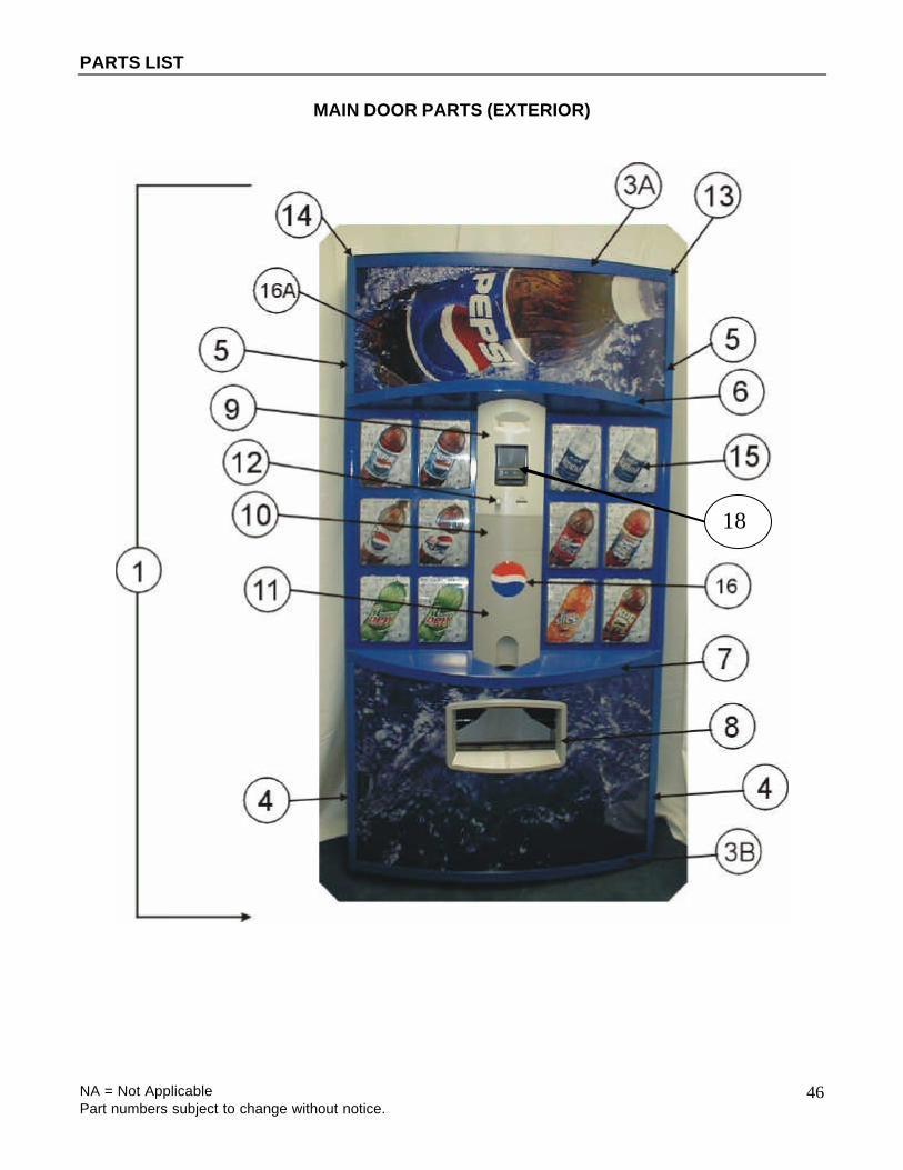
MAIN DOOR PARTS (EXTERIOR)
18
PARTS LIST
NA = Not Applicable Part numbers subject to change without notice.
47
MAIN DOOR PARTS (EXTERIOR)
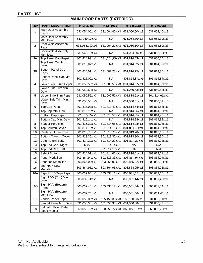
ITEM PART DESCRIPTION HT3 (276E) HT2 (501E) HT3 (501E) HT3 (600E)
1 Main Door Assembly Pepsi 631,054,00x.x3 631,004,40x.x3 631,050,00x.x3 631,052,40x.x3
Main Door Assembly Mtn. Dew 631,059,10x.x3 NA 631,054,70x.x3 631,052,30x.x3
2 Door Weld Assembly Pepsi 631,054,10X.03 631,004,20x.x3 631,050,10x.x3 631,052,50x.x3
Door Weld Assembly Mtn. Dew 631,062,10x.x3 NA 631,054,80x.x3 631,055,50x.x3
3A Top Panel Cap Pepsi 801,814,99x.x1 631,001,23x.x3 801,814,63x.x1 631,050,55x.x3
Top Panel Cap Mtn. Dew 801,815,07x.x1 NA 801,814,82x.x1 801,814,82x.x1
3B Bottom Panel Cap Pepsi 801,815,01x.x1 631,002,23x.x1 801,814,75x.x1 801,814,76x.x1
Bottom Panel Cap Mtn. Dew 801,815,09x.x1 NA 801,814,84x.x1 801,814,84x.x1
4 Lower Side Trim Pepsi 631,050,55x.x3 631,000,56x.x3 801,814,57x.x1 801,814,57x.x1
Lower Side Trim Mtn. Dew 631,050,58x.x3 NA 631,050,53x.x1 631,050,53x.x3
5 Upper Side Trim Pepsi 631,050,55x.x3 631,000,57x.x3 801,814,61x.x1 801,814,61x.x1
Upper Side Trim Mtn. Dew 631,050,56x.x3 NA 631,050,51x.x1 631,050,51x.x3
6 Top Cap Pepsi 801,815,03x.x1 801,813,40x.x1 801,814,64x.x1 801,814,54x.x1 Top Cap Mtn. Dew 801,815,12x.x1 NA 801,814,86x.x1 801,814,86x.x1 7 Bottom Cap Pepsi 801,815,05x.x1 801,813,50x.x1 801,814,65x.x1 801,814,75x.x1 Bottom Cap Mtn. Dew 801,815,14x.x1 NA 801,814,88x.x1 801,814,88x.x1 8 Spacer Port Trim 801,815,22x.x1 801,814,08x.x1 801,814,08x.x1 801,814,08x.x1 9 Top Column Cover 801,814,13x.x1 801,814,13x.x1 801,814,13x.x1 801,814,13x.x1
10 Center Column Cover 801,813,70x.x1 801,813,70x.x1 801,813,70x.x1 801,813,16x.x1 11 Bottom Column Cover 801,813,30x.x1 801,813,30x.x1 801,813,30x.x1 801,813,30x.x1 12 Coin Return Button 801,814,22x.x1 801,814,22x.x1 801,814,22x.x1 801,814,22x.x1 13 Top End Cap, Right N /A 801,814,14x.x1 NA N/A 14 Top End Cap, Left N/A 801,814,18x.x1 NA N/A 15 Select Button 801,814,01x.x1 801,814,01x.x1 801,814,01x.x1 801,814,01x.x1 16 Pepsi Medallion 803,864,94x.x1 801,813,33x.x1 803,864,94x.x1 803,864,94x.x1 16 Aquafina Medallion 803,865,02x.x1 803,865,02x.x1 803,865,02x.x1 803,865,02x.x1
16 Mountain Dew Medallion 803,864,95x.x1 803,864,95x.x1 803,864,95x.x1 803,864,95x.x1
16A Sign, HVV (Top) Pepsi 805,032,63x.x1 805,030,16x.x1 805,031,33x.x1 805,032,66x.x1
Sign, HVV (Top) Mtn. Dew 805,032,74x.x1 NA 805,031,44x.x1 805,031,45x.x1
16B Sign, HVV (Bottom) Pepsi 805,032,46x.x1 805,030,17x.x1 805,031,34x.x1 805,031,34x.x1
Sign, HVV (Bottom) Mtn. Dew 805,032,75x.x1 NA 805,031,46x.x1 805,031,46x.x1
17 Vandal Panel Pepsi 631,050,89x.x3 165,150,33x.x3 165,150,33x.x3 631,050,91x.x3 Vandal Panel Mtn. Dew 631,050,38x.x3 631,050,38x.x3 631,050,38x.x3 631,050,43x.x3
18 Validator Filler Plate (specify color) 360,050,72x.x3 360,050,72x.x3 360,050,72x.x3 360,050,72x.x3
PARTS LIST
NA = Not Applicable Part numbers subject to change without notice.
48
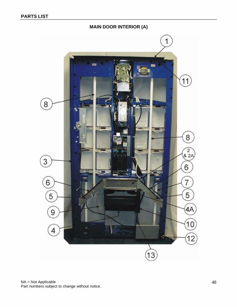
MAIN DOOR INTERIOR (A)

PARTS LIST
NA = Not Applicable Part numbers subject to change without notice.
49
MAIN DOOR INTERIOR (A)
ITEM PART DESCRIPTION HT3 (276E) HT2 (501E) HT3 (501E) HT3 (600E) 1 Rain Guard Pepsi 631,051,16x.x3 164,151,14x.x3 164,151,14x.x3 164,151,14x.x3 Rain Guard Mtn. Dew 631,062,60x.x3 NA 631,050,39x.x3 631,050,39x.x3 2 Cash Box 631,000,69x.x3 631,000,69x.x3 631,052,10x.x3 631,052,10x.x3 2a Vault Enclosure NA 631,005,30x.x3 NA NA 2b Cash Box Mount Weld Assy. 631,051,10x.x3 NA 631,051,10x.x3 631,051,10x.x3 3 Protective Plate, Door - Blue 631,050,89x.x3 165,150,33x.x3 165,150,33x.x3 631,050,91x.x3 Protective Plate, Door - Green 631,050,38x.x3 631,050,38x.x3 631,050,38x.x3 631,050,43x.x3 4 Delivery Port 801,810,02x.x1 801,810,02x.x1 801,810,02x.x1 801,810,02x.x1 4a Closure Strip 609,050,14x.x3 609,050,14x.x3 609,050,14x.x3 609,050,14x.x3 5 Lamp Bracket Support 631,050,04x.x3 631,001,26x.x3 631,001,26x.x3 631,001,26x.x3 6 Protective Edge 801,814,28x.x1 801,814,28x.x1 801,814,28x.x1 801,814,28x.x1 7 Lamp, T8,2’ F17T8/TL865 804,700,77x.x1 804,700,77x.x1 804,700,77x.x1 804,700,77x.x1 8 Lamp, T8,4’ F32T8/TL865 804,700,76x.x1 804,700,76x.x1 804,700,76x.x1 804,700,76x.x1 9 Drain Hose 801,904,03x.x1 801,904,03x.x1 801,904,03x.x1 801,904,03x.x1 10 Ballast T8 804,400,59x.x1 804,400,59x.x1 804,400,59x.x1 804,400,59x.x1 11 L Profile Gasket 803,601,11x.x1 903,600,54x.x1 903,600,54x.x1 903,600,54x.x1 12 Door Stop Bracket 592,051,19x.x3 592,051,19x.x3 592,051,19x.x3 592,051,19x.x3 13A W/A Port Support NA 631,050,70x.x3 631,050,70x.x3 631,050,70x.x3 13B Assy. Port Support Left 631,050,80x.x3 NA NA NA 13C Port Support Right 631,050,07x.x3 NA NA NA
2b Cash Box Mount with Tower

PARTS LIST
NA = Not Applicable Part numbers subject to change without notice.
50
MAIN DOOR INTERIOR (B)
18C
18C
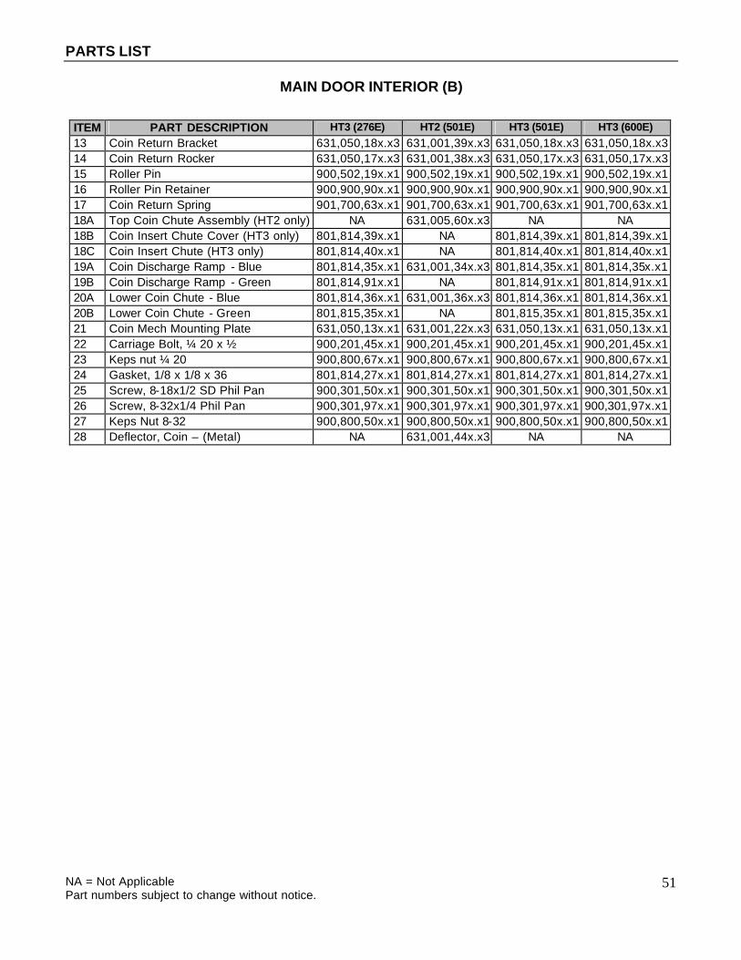
PARTS LIST
NA = Not Applicable Part numbers subject to change without notice.
51
MAIN DOOR INTERIOR (B)
ITEM PART DESCRIPTION HT3 (276E) HT2 (501E) HT3 (501E) HT3 (600E) 13 Coin Return Bracket 631,050,18x.x3 631,001,39x.x3 631,050,18x.x3 631,050,18x.x3 14 Coin Return Rocker 631,050,17x.x3 631,001,38x.x3 631,050,17x.x3 631,050,17x.x3 15 Roller Pin 900,502,19x.x1 900,502,19x.x1 900,502,19x.x1 900,502,19x.x1 16 Roller Pin Retainer 900,900,90x.x1 900,900,90x.x1 900,900,90x.x1 900,900,90x.x1 17 Coin Return Spring 901,700,63x.x1 901,700,63x.x1 901,700,63x.x1 901,700,63x.x1 18A Top Coin Chute Assembly (HT2 only) NA 631,005,60x.x3 NA NA 18B Coin Insert Chute Cover (HT3 only) 801,814,39x.x1 NA 801,814,39x.x1 801,814,39x.x1 18C Coin Insert Chute (HT3 only) 801,814,40x.x1 NA 801,814,40x.x1 801,814,40x.x1 19A Coin Discharge Ramp - Blue 801,814,35x.x1 631,001,34x.x3 801,814,35x.x1 801,814,35x.x1 19B Coin Discharge Ramp - Green 801,814,91x.x1 NA 801,814,91x.x1 801,814,91x.x1 20A Lower Coin Chute - Blue 801,814,36x.x1 631,001,36x.x3 801,814,36x.x1 801,814,36x.x1 20B Lower Coin Chute - Green 801,815,35x.x1 NA 801,815,35x.x1 801,815,35x.x1 21 Coin Mech Mounting Plate 631,050,13x.x1 631,001,22x.x3 631,050,13x.x1 631,050,13x.x1 22 Carriage Bolt, ¼ 20 x ½ 900,201,45x.x1 900,201,45x.x1 900,201,45x.x1 900,201,45x.x1 23 Keps nut ¼ 20 900,800,67x.x1 900,800,67x.x1 900,800,67x.x1 900,800,67x.x1 24 Gasket, 1/8 x 1/8 x 36 801,814,27x.x1 801,814,27x.x1 801,814,27x.x1 801,814,27x.x1 25 Screw, 8-18x1/2 SD Phil Pan 900,301,50x.x1 900,301,50x.x1 900,301,50x.x1 900,301,50x.x1 26 Screw, 8-32x1/4 Phil Pan 900,301,97x.x1 900,301,97x.x1 900,301,97x.x1 900,301,97x.x1 27 Keps Nut 8-32 900,800,50x.x1 900,800,50x.x1 900,800,50x.x1 900,800,50x.x1 28 Deflector, Coin – (Metal) NA 631,001,44x.x3 NA NA

PARTS LIST
NA = Not Applicable Part numbers subject to change without notice.
52
SELECT PANEL

PARTS LIST
NA = Not Applicable Part numbers subject to change without notice.
53
SELECT PANEL
ITEM PART DESCRIPTION HT3 (276E) HT2 (501E) HT3 (501E) HT3 (600E) 1 Select Panel Assy., Right (shown) Pepsi 631,056,80x.x3 631,004,20x.x3 631,051,60x.x3 631,051,60x.x3 Select Panel Assy., Right (shown) Mtn. Dew 631,002,20x.x3 NA 631,054,90x.x3 631,054,90x.x3 2 Select Panel Assy., Left (not shown) Pepsi 631,056,50x.x3 631,005,40x.x3 631,051,70x.x3 631,051,70x.x3 Select Panel Assy., Left (not shown) Mtn. Dew 631,062,40x.x3 NA 631,055,10x.x3 631,055,10x.x3 3 Upper Switch/Button Bracket 631,050,64x.x3 631,001,29x.x3 631,050,16x.x3 631,050,16x.x3 4 Lower Switch/Button Bracket NA 631,001,31x.x3 NA NA 5 Stud Select Panel Assembly, Left Pepsi 631,056,50x.x3 631,005,10x.x3 631,051,90x.x3 631,051,90x.x3 Stud Select Panel Assembly, Left Mtn. Dew 631,062,50x.x3 NA 631,055,20x.x3 631,055,20x.x3 6 Stud Select Panel Assembly, Right Pepsi 631,056,90x.x3 631,004,60x.x3 631,051,80x.x3 631,051,80x.x3 Stud Select Panel Assembly, Right Mtn. Dew 631,062,30x.x3 NA 631,055,00x.x3 631,055,00x.x3 7 Select Switch 804,101,08x.x1 804,101,08x.x1 804,101,08x.x1 804,101,08x.x1 8 Select Button 801,814,01x.x1 801,814,01x.x1 801,814,01x.x1 801,814,01x.x1 9 Sold out Light 804,700,75x.x1 804,700,75x.x1 804,700,75x.x1 804,700,75x.x1
10 Sold out Light Mount 801,814,15x.x1 801,814,15x.x1 801,814,15x.x1 801,814,15x.x1 11 Button Return Spring 801,306,04x.x1 801,306,04x.x1 801,306,04x.x1 801,306,04x.x1 12 Philpan Sems Screw 6-32 x 1 800,303,35x.x1 800,303,35x.x1 800,303,35x.x1 800,303,35x.x1 13A Gasket, 1/4 x .154 x 13 NA 801,814,25x.x1 801,814,25x.x1 801,814,25x.x1 13B Gasket ¼ x .154 x 6.75 801,815,39x.x1 NA NA NA 14A Gasket, 1/8 x 1/8 x 27 NA 801,814,24x.x1 NA NA 14B Gasket 1/8 x 1/8 x 28.5 801,815,40x.x1 NA NA NA 15 Gasket, 1/8 x 1/8 x 13.5 NA 801,814,26x.x1 NA NA 16 8-32 Keps Nut 900,800,50x.x1 900,800,50x.x1 900,800,50x.x1 900,800,50x.x1 17 Wire Tie 7 1/2 “ 901,902,01x.x1 901,902,01x.x1 901,902,01x.x1 901,902,01x.x1 18 Button Decal 803,869,25x.x1 NA NA NA

PARTS LIST
NA = Not Applicable Part numbers subject to change without notice.
54
T8 LIGHTING
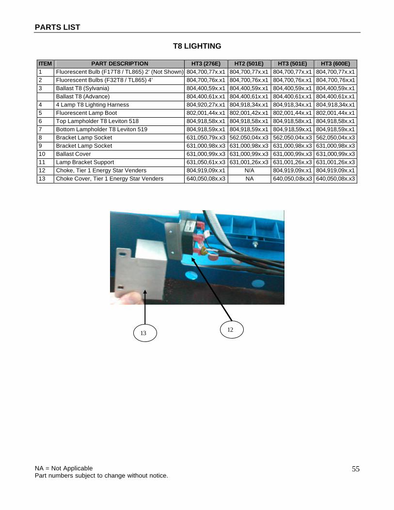
PARTS LIST
NA = Not Applicable Part numbers subject to change without notice.
55
T8 LIGHTING
ITEM PART DESCRIPTION HT3 (276E) HT2 (501E) HT3 (501E) HT3 (600E) 1 Fluorescent Bulb (F17T8 / TL865) 2’ (Not Shown) 804,700,77x.x1 804,700,77x.x1 804,700,77x.x1 804,700,77x.x1 2 Fluorescent Bulbs (F32T8 / TL865) 4’ 804,700,76x.x1 804,700,76x.x1 804,700,76x.x1 804,700,76x.x1 3 Ballast T8 (Sylvania) 804,400,59x.x1 804,400,59x.x1 804,400,59x.x1 804,400,59x.x1 Ballast T8 (Advance) 804,400,61x.x1 804,400,61x.x1 804,400,61x.x1 804,400,61x.x1 4 4 Lamp T8 Lighting Harness 804,920,27x.x1 804,918,34x.x1 804,918,34x.x1 804,918,34x.x1 5 Fluorescent Lamp Boot 802,001,44x.x1 802,001,42x.x1 802,001,44x.x1 802,001,44x.x1 6 Top Lampholder T8 Leviton 518 804,918,58x.x1 804,918,58x.x1 804,918,58x.x1 804,918,58x.x1 7 Bottom Lampholder T8 Leviton 519 804,918,59x.x1 804,918,59x.x1 804,918,59x.x1 804,918,59x.x1 8 Bracket Lamp Socket 631,050,79x.x3 562,050,04x.x3 562,050,04x.x3 562,050,04x.x3 9 Bracket Lamp Socket 631,000,98x.x3 631,000,98x.x3 631,000,98x.x3 631,000,98x.x3 10 Ballast Cover 631,000,99x.x3 631,000,99x.x3 631,000,99x.x3 631,000,99x.x3 11 Lamp Bracket Support 631,050,61x.x3 631,001,26x.x3 631,001,26x.x3 631,001,26x.x3 12 Choke, Tier 1 Energy Star Venders 804,919,09x.x1 N/A 804,919,09x.x1 804,919,09x.x1 13 Choke Cover, Tier 1 Energy Star Venders 640,050,08x.x3 NA 640,050,08x.x3 640,050,08x.x3
12 13

PARTS LIST
NA = Not Applicable Part numbers subject to change without notice.
56
ELECTRONIC COMPONENTS

PARTS LIST
NA = Not Applicable Part numbers subject to change without notice.
57
ELECTRONICS COMPONENTS
ITEM PART DESCRIPTION HT3 (276E) HT2 (501E) HT3 (501E) HT3 (600E) 1 Electronic Lock Assembly 805,202,44x.x1 805,202,44x.x1 805,202,44x.x1 805,202,44x.x1 2 Electronic Lock Light Pipe 801,815,42x.x1 801,814,19x.x1 801,814,19x.x1 801,814,19x.x1 3 Machine Controller 631,053,30x.x3 804,918,15x.x1 631,053,30x.x3 631,053,30x.x3 4 Machine Controller Base 801,306,15x.x1 801,813,45x.x1 801,306,15x.x1 801,306,15x.x1 5 Machine Controller Cover 801,306,16x.x1 631,000,68x.x3 801,306,16x.x1 801,306,16x.x1 6 Universal Controller NA 804,916,31x.x1 NA NA 7 Display (Vacuum Fluorescent) 804,918,69x.x1 804,918,69x.x1 804,918,69x.x1 804,918,69x.x1 8 Transformer 804,909,80x.x1 804,909,80x.x1 804,909,80x.x1 804,909,80x.x1 9 Machine Controller EPROM NA 804,917,61x.x1 NA NA 10 Universal Controller EPROM NA 804,916,25x.x1 NA NA 11 Fuse 6 Amp (F2) 804,910,93x.x1 804,910,93x.x1 804,910,93x.x1 804,910,93x.x1 12 Fuse 1.6 Amp (F1) 804,800,71x.x1 804,800,71x.x1 804,800,71x.x1 804,800,71x.x1 13 Control Board Assembly HT3 631,053,30x.x1 NA 631,053,30x.x1 631,053,30x.x1 14 HT3 Eprom Control Board 804,919,24x.x1 NA 804,919,24x.x1 804,919,24x.x1

PARTS LIST
NA = Not Applicable Part numbers subject to change without notice.
58
INNER DOOR

PARTS LIST
NA = Not Applicable Part numbers subject to change without notice.
59
INNER DOOR
ITEM PART DESCRIPTION HT3 (276E) HT2 (501E) HT3 (501E) HT3 (600E) 1 Inner Door Assembly 631,057,50x.x3 631,004,90x.x3 631,004,90x.x3 631,053,70x.x3 2 Inner Door Gasket 801,812,29x.x1 801,804,06x.x1 801,804,06x.x1 801,812,31x.x1 3 Discharge Frame Assembly 801,809,16x.x1 801,809,16x.x1 801,809,16x.x1 801,809,16x.x1 4 Discharge Frame Retainer 801,809,15x.x1 801,809,15x.x1 801,809,15x.x1 801,809,15x.x1 5 Pull Knob 901,501,70x.x1 901,501,70x.x1 901,501,70x.x1 901,501,70x.x1 6 Carriage Bolt ¼-20x¼ 900,201,23x.x1 900,201,23x.x1 900,201,23x.x1 900,201,23x.x1 7 Inner Door Bushing 801,806,42x.x1 801,806,42x.x1 801,806,42x.x1 801,806,42x.x1 8 Bushing Retainer 801,806,43x.x1 801,806,43x.x1 801,806,43x.x1 801,806,43x.x1 9 Plastic Bearing 901,803,71x.x1 901,803,71x.x1 901,803,71x.x1 901,803,71x.x1 10 Top Hinge 169,053,00x.x3 169,053,00x.x3 169,053,00x.x3 169,053,00x.x3 11 Bottom Hinge 169,051,10x.x3 169,051,10x.x3 169,051,10x.x3 169,051,10x.x3 12 Inner Door Lock Kit 360,010,30x.x4 360,010,30x.x4 360,010,30x.x4 360,010,30x.x4

PARTS LIST
NA = Not Applicable Part numbers subject to change without notice.
60
HARNESSING Dual Board (HT2)

PARTS LIST
NA = Not Applicable Part numbers subject to change without notice.
61
HARNESSING
Dual Board (HT2)
ITEM PART DESCRIPTION HT2 (501E) MACHINE BOARD HARNESS
1 Board to board interface harness (J3 of machine board to J14 of universal board) 804,917,34x.x1
2 Motor Extension Harness, 90 inches (P10 to bottom of door) 804,909,29x.x1
3 Temp Sensor and Relay Extension Harness (P6 and P2 to bottom of door) 804,917,43x.x1
4 Cabinet Extension Harness, 80 inches (J1 to bottom of door) 804,913,96x.x1
5 Board Power Harness (J2 to transformer) (includes transformer) 804,909,80x.x1
UNIVERSAL CONTROLLER HARNESSES
6 Mdb AND Lock Power Harness (P9 to lock and MDB peripherals) 804,918,62x.x1
7 Harness, Electronic Lock 804,918,28x.x1 8 Jumper, Electronic Lock 804,918,66x.x1
9 Select Panel Harness (P3 to select swtiches) 804,917,31x.x1
10 Sold Out / Ready to Vend Harness (P4 and P4A to sold out / ready to vend LED’s and switch) 804,918,27x.x1
11 DEX Harness (P1 to DEX jack) 804,917,32x.x1
12 Display Harness (P2 to display board) (Not Shown) 804,918,61x.x1 13 Temp Sensor board 804,917,44x.x1 14 Temp Sensor Harness 804,917,41x.x1

PARTS LIST
NA = Not Applicable Part numbers subject to change without notice.
62
HARNESSING
Single Board (HT3)

PARTS LIST
NA = Not Applicable Part numbers subject to change without notice.
63
HARNESSING
Single Board (HT3) ITEM PART DESCRIPTION HT3 (276E) HT3 (501E) HT3 (600E) 2 Motor Extension Harness, (see page 61) 804,913,95x.x1 804,909,29x.x1 804,909,29x.x1 2 Motor Harness (see page 61) 804,912,72x.x1 804,912,56x.x1 804,912,56x.x1 4 Cabinet Harness (see page 61) 804,912,73x.x1 804,912,57x.x1 804,912,57x.x1 4 Cabinet Extension Harness, 80 inches J4 to (see page 61) 804,913,96x.x1 804,913,96x.x1 804,913,96x.x1 5 Board Power Harness (including transformer) J1 (see page 61) 804,909,80x.x1 804,909,80x.x1 804,909,80x.x1 7 Harness Electronic Lock (see page 61) 804,918,28x.x1 804,918,28x.x1 804,918,28x.x1 8 Jumper Electronic Lock (see page 61) 804,918,66x.x1 804,918,66x.x1 804,918,66x.x1 9A Select Switch Harness 1 – 6 (Jumper off common) NA 804,919,17x.x1 804,919,17x.x1 9B Select Switch Harness 7 – 12 (Jumper off common) NA 804,919,18x.x1 804,919,18x.x1 9C Select Switch Common Harness (P4 to select switches) 804,919,16x.x1 804,919,16x.x1 804,919,16x.x1 9D Select Switch Harness 1-3 804,919,73x.x1 NA NA 9E Select Switch Harness 4-6 804,919,74x.x1 NA NA 11 66” DEX Harness 804,907,83x.x1 804,907,83x.x1 804,907,83x.x1 13 Temp Sensor & Relay Harness 804,919,22x.x1 804,919,22x.x1 804,919,22x.x1 14 Display Harness (P3 to display board) (not shown) 804,919,21x.x1 804,919,21x.x1 804,919,21x.x1 16 Secondary DEX Harness 804,913,97x.x1 804,913,97x.x1 804,913,97x.x1 17 Sold Out Light Kit NA 631,053,50x.x3 631,053,50x.x3 18 MDB and Lock Power Harness (P8 & P5 to coin mech & lock) 804,919,19x.x1 804,919,19x.x1 804,919,19x.x1 19 Power Cord, Detachable 804,917,28x.x1 804,917,28x.x1 804,917,28x.x1 20 Main Wiring Harness, Detachable 804,917,26x.x1 804,917,26x.x1 804,917,26x.x1 21 T8 Lighting Harness 4 Lamp 804,202,27x.x1 804,202,27x.x1 804,202,27x.x1 22 Triteq Lock Battery Back Up Harness 804,918,28x.x1 804,918,28x.x1 804,918,28x.x1 23 Triteq Lock Battery Back Up Harness Nut !/4-36 800,801,26x.x1 800,801,26x.x1 800,801,26x.x1
24 ECM Evaporator Fan Harness (Energy Star Venders 0197-6978CC & higher) 804,922,37x.x1 804,922,37x.x1 804,922,37x.x1
25 ECM Evaporator Fan Choke Extension Harness (Energy Star Venders 0197-6978CC & higher) 804,922,52x.x1 804,922,52x.x1 804,922,52x.x1
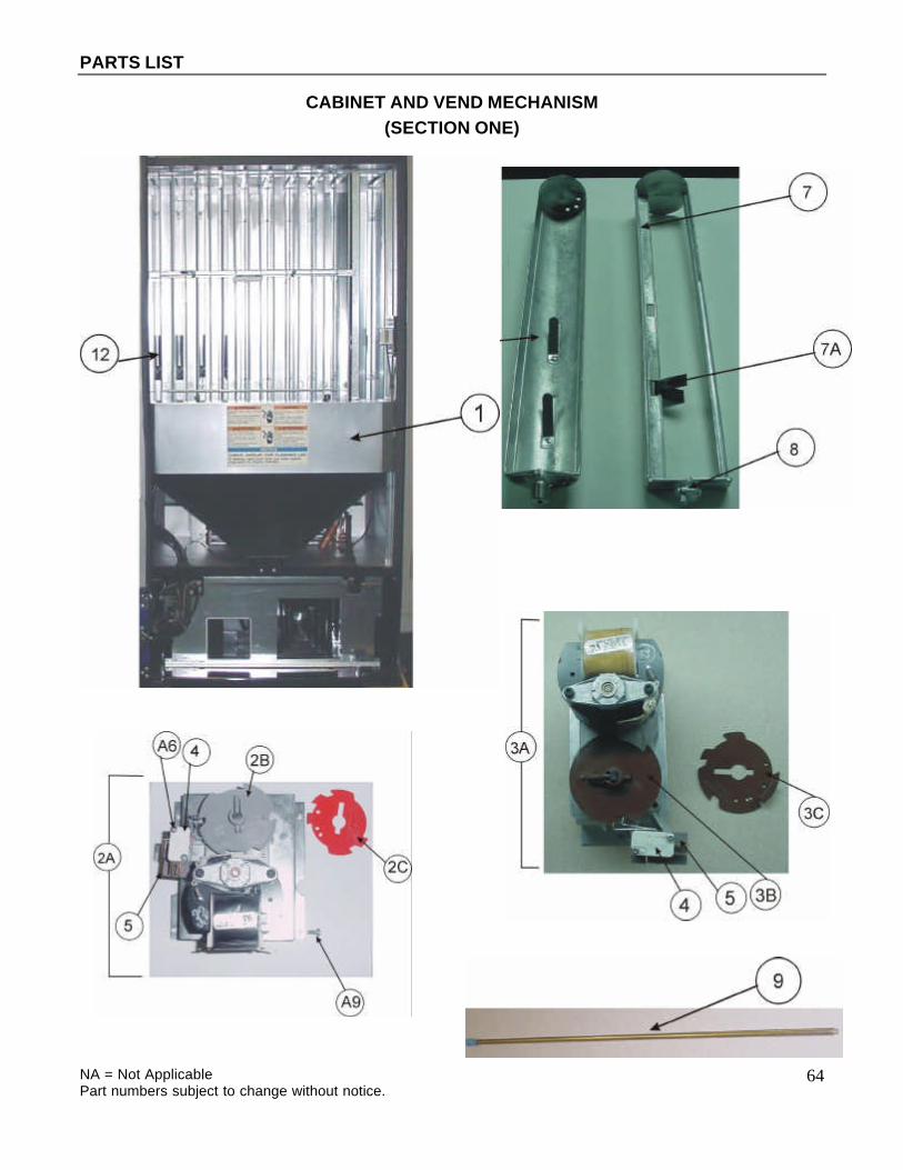
PARTS LIST
NA = Not Applicable Part numbers subject to change without notice.
64
CABINET AND VEND MECHANISM (SECTION ONE)

PARTS LIST
NA = Not Applicable Part numbers subject to change without notice.
65
CABINET AND VEND MECHANISM (SECTION ONE)
ITEM DESCRIPTION HT3 (276E) HT2 (501E) HT3 (501E) HT3 (600E) 1 Vend Motor Cover Assy. 615,070,07x.x3 609,070,43x.x3 609,070,43x.x3 609,070,43x.x3 1A Clamp Nylon Cable 3/4 (2) not shown 901,900,55x.x1 901,900,55x.x1 901,900,55x.x1 901,900,55x.x1
2A Vend Motor Assy., Wide HVV (Electronic)
NA 609,070,70x.x3 609,070,70x.x3 609,070,70x.x3
2B Vend Cam, Wide Column Grey NA 801,809,80x.x1 801,809,80x.x1 801,809,80x.x1 2C Adjustable Cam, Wide Column Red NA 801,809,79x.x1 801,809,79x.x1 801,809,79x.x1
3A Vend Motor Assy., Narrow HVV (Electronic)
609,070,90x.x3 609,070,90x.x3 609,070,90x.x3 609,070,90x.x3
3B Vend Cam, Narrow Column Brown 801,806,18x.x1 801,806,18x.x1 801,806,18x.x1 801,806,18x.x1 3C Adjustable Cam, Narrow Column Brown 801,806,61x.x1 801,806,61x.x1 801,806,61x.x1 801,806,61x.x1 4 Vend Motor Switch Switch Electronic 804,100,73x.x1 804,100,73x.x1 804,100,73x.x1 804,100,73x.x1 5 Vend Motor Switch Insulator 905,800,33x.x1 905,800,33x.x1 905,800,33x.x1 905,800,33x.x1 6 Vend Rotor - Narrow Column 801,201,56x.x1 801,201,56x.x1 801,201,56x.x1 801,201,56x.x1 7 Vend Oscillator - Wide Column 801,201,57x.x1 801,201,57x.x1 801,201,57x.x1 801,201,57x.x1 7A Package Retainer - Oscillator NA 801,807,87x.x1 801,807,87x.x1 801,807,87x.x1 8 Nyliner Front Wide Column Only (#8L2-FF) NA 901,804,23x.x1 901,804,23x.x1 901,804,23x.x1 Rear All Columns NA 801,803,17x.x1 801,803,17x.x1 801,803,17x.x1 9 Rod and Spring Assembly 800,503,00x.x1 800,503,00x.x1 800,503,00x.x1 800,503,00x.x1 10 Tubes for Rod and Spring Assy. Red 801,903,23x.x1 801,903,23x.x1 801,903,23x.x1 801,903,23x.x1 Yellow 801,903,25x.x1 801,903,25x.x1 801,903,25x.x1 801,903,25x.x1 White 801,903,24x.x1 801,903,24x.x1 801,903,24x.x1 801,903,24x.x1 Black 801,904,04x.x1 801,904,04x.x1 801,904,04x.x1 801,904,04x.x1 11 Vend Motor Cover Trim 801,807,85x.x1 801,807,85x.x1 801,807,85x.x1 801,807,85x.x1 12 Rear Air Deflector 801,903,35x.x1 801,903,29x.x1 801,903,29x.x1 801,903,29x.x1
A6 Screw, Vend Motor #4-24x3/4 (single switch) 900,300,47xx.1 900,300,47xx.1 900,300,47xx.1 900,300,47xx.1
A9 Screw, Phil Pan 8-32x3/8 900,301,56x.x1 900,301,56x.x1 900,301,56x.x1 900,301,56x.x1

PARTS LIST
NA = Not Applicable Part numbers subject to change without notice.
66
CABINET AND VEND MECHANISM (SECTION TWO)

PARTS LIST
NA = Not Applicable Part numbers subject to change without notice.
67
CABINET AND VEND MECHANISM (SECTION TWO)
ITEM DESCRIPTION HT3 (276E) HT2 (501E) HT3 (501E) HT3 (600E)
1A Sold-Out Switch Assy. Electronic (w/ gold cross point) - Xenoy 1731 804,100,75x.x1 804,100,75x.x1 804,100,75x.x1 804,100,75x.x1
1B Sold-Out Paddle Standard Emodel (shown) 432,070,19x.x3 432,070,19x.x3 432,070,19x.x3 432,070,19x.x3 Special Use Only - E-Models 609,070,19x.x3 609,070,19x.x3 609,070,19x.x3 609,070,19x.x3 Narrow - Special Use Only E-Models 432,070,17x.x3 432,070,17x.x3 432,070,17x.x3 432,070,17x.x3 1C Sold-Out Paddle Spring 901,700,74x.x1 901,700,74x.x1 901,700,74x.x1 901,700,74x.x1 2A Front, Left Mechanism Support (shown) NA 609,070,22x.x3 NA NA 2B Rear Mechanism Support (shown) 497,070,01x.x3 497,070,01x.x3 497,070,01x.x3 497,070,01x.x3
2C Front, Right Mechanism Support (not shown) NA 609,070,23x.x3 NA NA
3A Evaporator Fan Motor Assy. 115V 609,044,30x.x3 491,000,20x.x3 609,044,30x.x3 609,044,30x.x3 220-240V NA 491,140,40x.x3 NA NA 120V/60Hz Energy Star 646,040,40x.x3 NA 646,040,40x.x3 646,040,40x.x3 3B Evaporator Fan Motor 115V 804,501,12x.x1 609,044,40x.x3 804,501,12x.x1 804,501,12x.x1 220-240V / 50 Hz 609,044,60x.x3 609,044,60x.x3 609,044,60x.x3 609,044,60x.x3 120V/60Hz Energy Star 804,501,28x.x1 NA 804,501,28x.x1 804,501,28x.x1 3C Evaporator Fan Motor Bracket 164,040,08x.x3 164,040,08x.x3 164,040,08x.x3 164,040,08x.x3
3D Evaporator Fan Blade All Styles (AD775CW32S or FV775CW30S)
801,303,27x.x1 801,303,27x.x1 801,303,27x.x1 801,303,27x.x1
3E Evaporator Fan Harness Prior to Energy Star 0197-6978CC 804,914,36x.x1 804,914,35x.x1 804,914,35x.x1 804,914,35x.x1 Energy Star 0197-6978CC 804,922,37x.x1 NA 804,922,37x.x1 804,922,37x.x1
3F Evaporator Fan Choke Extension Harness Energy Star 0197-6978CC 804,922,52x.x1 NA 804,922,52x.x1 804,922,52x.x1
3G Choke Energy Star 0197-6978CC 804,920,41x.x1 NA 804,920,41x.x1 804,920,41x.x1 4 Wire Shield 615,070,12x.x3 267,070,37x.x3 267,070,37x.x3 267,070,37x.x3 5A Foam Block, EPS 903,300,77x.x1 903,300,77x.x1 903,300,77x.x1 903,300,77x.x1 5B Hinge Pocket Cover 169,000,13x.x3 169,000,13x.x3 169,000,13x.x3 169,000,13x.x3 6 Journal NA 176,072,11x.x3 176,072,11x.x3 176,072,11x.x3 7 Shims Flat Shim 3/32" (wide column) Waffle NA 801,812,04x.x1 801,812,04x.x1 801,812,04x.x1 Short Flat Shim 3/32" (wide column) NA 801,809,81x.x1 801,809,81x.x1 801,809,81x.x1
3A
3B 3F
3E

PARTS LIST
NA = Not Applicable Part numbers subject to change without notice.
68
Can Stop Shim, Right (narrow column) 805,701,14x.x1 805,701,14x.x1 805,701,14x.x1 805,701,14x.x1 Bottle Shim, Right (narrow column) 805,701,15x.x1 805,701,15x.x1 805,701,15x.x1 805,701,15x.x1
Bottle Shim, Right (narrow column) Expose Stiffener
801,304,96x.x1 801,304,96x.x1 801,304,96x.x1 801,304,96x.x1
Angle Shim (wide column) NA 610,070,06x.x3 610,070,06x.x3 610,070,06x.x3 Angle Shim (narrow column) 609,010,10x.x3 609,010,10x.x3 609,010,10x.x3 609,010,10x.x3 Rotor Shim 330 ml x 4 801,305,21x.x1 801,305,21x.x1 801,305,21x.x1 801,305,21x.x1 Shim 330 ml x 4 Can, Narrow Column 609,070,53x.x3 609,070,53x.x3 609,070,53x.x3 609,070,53x.x3 Can Stop Shim, 330 ml (3 deep) 609,070,71x.x3 609,070,71x.x3 609,070,71x.x3 609,070,71x.x3 Shim 25 cl x 4 Can, Narrow Column 609,070,56x.x3 609,070,56x.x3 609,070,56x.x3 609,070,56x.x3
Bottom Shim, Exposed Stiffener Extended Lip 609,070,65x.x3 609,070,65x.x3 609,070,65x.x3 609,070,65x.x3
Flat Shim 3/32 Large Product 801,811,05x.x1 801,811,05x.x1 801,811,05x.x1 801,811,05x.x1 Shim Back 609,071,02x.x3 609,071,02x.x3 609,071,02x.x3 609,071,02x.x3 Can Stop Shim Long Lip 609,070,64x.x3 609,070,64x.x3 609,070,64x.x3 609,070,64x.x3 8 Nyliner Front Wide Column Only (#8L2-FF) NA 901,804,23x.x1 901,804,23x.x1 901,804,23x.x1 Rear All Columns 801,803,17x.x1 801,803,17x.x1 801,803,17x.x1 801,803,17x.x1 9 Chute, Can/Bottle HVV Plastic 631,057,90x.x3 609,077,80x.x3 609,077,80x.x3 609,077,80x.x3 9A Screw, 8-32x1/2 Sems Phil Pan 900,303,09x.x1 900,303,09x.x1 900,303,09x.x1 900,303,09x.x1 9B Strip, Poly Foam 34” (under chute) 803,301,30x.x1 803,301,30x.x1 803,301,30x.x1 803,301,30x.x1 A3 Screw, Phil Pan 10-32x5/16" 900,301,83x.x1 900,301,83x.x1 900,301,83x.x1 900,301,83x.x1
B5 Speed Nut (evaporator fan & condenser fan) 900,800,85x.x1 900,800,85x.x1 900,800,85x.x1 900,800,85x.x1

PARTS LIST
NA = Not Applicable Part numbers subject to change without notice.
69
CABINET AND VEND MECHANISM (SECTION THREE)

PARTS LIST
NA = Not Applicable Part numbers subject to change without notice.
70
CABINET AND VEND MECHANISM (SECTION THREE)
ITEM DESCRIPTION HT3 (276E) HT2 (501E) HT3 (501E) HT3 (600E) 1 Foam Cabinet Assy. HVV 631,061,10x.x3 609,001,20x.x3 631,060,40x.x3 631,060,50x.x3 2A Stack Assy. 12 oz. Cans 615,070,00x.x3 609,071,20x.x3 609,071,20x.x3 610,070,50x.x3 20 oz. Bottles 615,071,30x.x3 609,071,50x.x3 609,071,50x.x3 610,070,80x.x3 330 ml Can 4 deep 609,074,90x.x3 609,074,40x.x3 609,074,40x.x3 610,071,70x.x3 2B Stack Sub Assy. (Not Shown) 615,071,40x.x3 609,071,10x.x3 609,071,10x.x3 610,070,40x.x3 3A Rear Spacer Assy. Wide Column NA 498,071,30x.x3 498,071,30x.x3 497,073,10x.x3 3B Rear Spacer Assy. Narrow Column 498,071,40x.x3 498,071,40x.x3 498,071,40x.x3 497,073,20x.x3 3C Latch Spring Wide NA 901,700,88x.x1 901,700,88x.x1 901,700,88x.x1 Narrow 901,700,86x.x1 901,700,86x.x1 901,700,86x.x1 901,700,86x.x1
4A Plate, Protective LS Ext. Hinge (Specify Blue) 594,020,14x.x3 609,000,01x.x3 594,020,14x.x3 594,020,17x.x3
4B Plate, Protective RT Cab (Specify Blue) 165,000,04x.x3 165,000,04x.x3 165,000,04x.x3 164,000,04x.x3 5 Environmental Control Kit 631,004,00x.x4 631,004,00x.x4 631,004,00x.x4 631,004,00x.x4
5A Relay (3) (Environmental Control Venders Only)
804,200,26x.x1 804,200,26x.x1 804,200,26x.x1 804,200,26x.x1
5B Plate Mounting Relay (used on all HVV Machines) 631,000,64x.x3 631,000,64x.x3 631,000,64x.x3 631,000,64x.x3
5C Filter (powerline) (All HT2 501E) NA 804,917,96x.x1 NA NA
5D Choke (Used on all HVV Machines) (replaces Filter – 5C) 804,919,09x.x1 804,919,09x.x1 804,919,09x.x1 804,919,09x.x1
6A Label, Light Relay (Environmental Control Venders Only)
803,860,68x.x1 803,860,68x.x1 803,860,68x.x1 803,860,68x.x1
6B Label, Fan Relay (Environmental Control Venders Only) 803,860,69x.x1 803,860,69x.x1 803,860,69x.x1 803,860,69x.x1
6C Label, Compressor Relay (Environmental Control Venders Only) 803,860,70x.x1 803,860,70x.x1 803,860,70x.x1 803,860,70x.x1
7 Cabinet Front Stiffener Plate 596,040,04x.x3 594,021,10x.x3 594,021,10x.x3 594,021,10x.x3 8 Trim Access Hole Stiffener 801,807,10x.x1 801,807,10x.x1 801,807,10x.x1 801,807,10x.x1 9 Caterpillar Grommeting 801,809,93x.x1 801,809,93x.x1 801,809,93x.x1 801,809,93x.x1 10 Mullion 801,806,28x.x1 801,806,21x.x1 801,806,23x.x1 801,806,23x.x1 11 Mullion Cover 801,303,83x.x1 801,303,83x.x1 801,303,83x.x1 801,303,83x.x1 12 Kydex Door (not shown) 801,903,34x.x1 801,903,34x.x1 801,903,34x.x1 801,903,34x.x1 13 Choke / Relay Plate Assy. 631,007,30x.x3 NA 631,007,30x.x3 631,007,30x.x3 A4 Screw, Phil Pan 8-18x1/2 900,301,50x.x1 900,301,50x.x1 900,301,50x.x1 900,301,50x.x1
A5 Screw, Phil Pan Swage Form #8-32x1/4"
900,301,97x.x1 900,301,97x.x1 900,301,97x.x1 900,301,97x.x1
A9 Screw, Phil Pan 8-32x3/8 900,301,56x.x1 900,301,56x.x1 900,301,56x.x1 900,301,56x.x1 A10 Screw, Machine #6-32x1 1/4" 900,201,31x.x1 900,201,31x.x1 900,201,31x.x1 900,201,31x.x1 A14 Screw, Phil Pan 10-32x1 1/4 900,301,81x.x1 900,301,81x.x1 900,301,81x.x1 900,301,81x.x1 A16 Screw, Phil Pan Sems 8-18x1/2" 900,301,65x.x1 900,301,65x.x1 900,301,65x.x1 900,301,65x.x1 A17 Screw, Type F 1/4-20x5/8 (Stack Bolts) 900,302,01x.x1 900,302,01x.x1 900,302,01x.x1 900,302,01x.x1 A19 Screw, Phil Pan 10-32x5/8 900,901,51x.x1 900,901,51x.x1 900,901,51x.x1 900,901,51x.x1 A21 Screw, Phil Pan 8-18x1/2 900,301,98x.x1 900,301,98x.x1 900,301,98x.x1 900,301,98x.x1 A26 Screw, Phil Pan 8-18x3/4 800,303,15x.x1 800,303,15x.x1 800,303,15x.x1 800,303,15x.x1 B2 Keps Nut 1/4"-20 900,800,67x.x1 900,800,67x.x1 900,800,67x.x1 900,800,67x.x1
C6 Lockwasher, Shakeproof 5/8" (1132-00-00-0551)
900,700,89x.x1 900,700,89x.x1 900,700,89x.x1 900,700,89x.x1
C8 Washer, Shakeproof (4610-16-01-0551) 900,700,62x.x1 900,700,62x.x1 900,700,62x.x1 900,700,62x.x1

PARTS LIST
NA = Not Applicable Part numbers subject to change without notice.
71
E9 Carriage Bolt 1/4-20x5/8 800,303,19x.x1 800,303,19x.x1 800,303,19x.x1 800,303,19x.x1 F1 Pop Rivet, Aluminum 1/4" 901,100,43x.x1 901,100,43x.x1 901,100,43x.x1 901,100,43x.x1 F5 Pop Rivet, Steel (Zinc Plated) 1/8" 901,100,61x.x1 901,100,61x.x1 901,100,61x.x1 901,100,61x.x1 F6 Pop Rivet, Aluminum 1/8" 901,100,53x.x1 901,100,53x.x1 901,100,53x.x1 901,100,53x.x1
H2 Tinnerman Clip, Fan Shroud (C5207-014-3B)
900,901,89x.x1 900,901,89x.x1 900,901,89x.x1 900,901,89x.x1
H7 Hole Plug, Snap In - 1 1/4 801,807,01x.x1 801,807,01x.x1 801,807,01x.x1 801,807,01x.x1
I6 Clamp, Nylon 5/16 Black Heyco 3355 or Dennison 10159 900,901,79x.x1 900,901,79x.x1 900,901,79x.x1 900,901,79x.x1
I7 Clamp, Nylon 1/2" Heyco 3328 900,901,80x.x1 900,901,80x.x1 900,901,80x.x1 900,901,80x.x1

PARTS LIST
NA = Not Applicable Part numbers subject to change without notice.
72
CABINET INTERIOR

PARTS LIST
NA = Not Applicable Part numbers subject to change without notice.
73
CABINET INTERIOR ITEM DESCRIPTION HT3 (276E) HT2 (501E) HT3 (501E) HT3 (600E) 1 Lock Housing 1A Assy. Vertical Recpt Mount 631,050,45x.x3 631,050,45x.x3 631,050,45x.x3 631,050,45x.x3 1B Plate Assy (Black) NA 801,306,05x.x1 801,306,05x.x1 801,306,05x.x1 1C Screw 1/4x20x1 900,301,73x.x1 900,301,73x.x1 900,301,73x.x1 900,301,73x.x1 1D Nut 1/4-20 Nylong Insert, Locking 800,303,48x.x1 800,303,48x.x1 800,303,48x.x1 800,303,48x.x1 1E E-Lock Shim NA 631,000,76x.x3 631,000,76x.x3 631,000,76x.x3 2 Gate, Wire 801,401,76x.x1 801,401,72x.x1 801,401,72x.x1 801,401,72x.x1 3 Wire Gate Latch Lock & Guide 801,401,77x.x1 801,401,77x.x1 801,401,77x.x1 801,401,77x.x1 4 Wire Gate Bracket Top 609,070,36x.x3 609,070,36x.x3 609,070,36x.x3 609,070,36x.x3 5 Label - Close Gate 805,029,45x.x1 805,029,45x.x1 805,029,45x.x1 805,029,45x.x1 6 Clamp, Nylon Cable 1/2" (Not Shown) 900,901,80x.x1 900,901,80x.x1 900,901,80x.x1 900,901,80x.x1 7 Leveling Leg 5/8"-11x2 1/16" 900,502,49x.x1 900,502,49x.x1 900,502,49x.x1 900,502,49x.x1 8 Mounting Bracket, Rear (Not Shown) 609,070,24x.x3 609,070,24x.x3 609,070,24x.x3 609,070,24x.x3 A4 Screw, Phil Pan 8-18x1/2 900,301,50x.x1 900,301,50x.x1 900,301,50x.x1 900,301,50x.x1
A5 Screw, Phil Pan Swage Form #8-32x1/4"
900,301,97x.x1 900,301,97x.x1 900,301,97x.x1 900,301,97x.x1
A9 Screw, Phil Pan 8-32x3/8 900,301,56x.x1 900,301,56x.x1 900,301,56x.x1 900,301,56x.x1 A10 Screw, Machine #6-32x1 1/4" 900,201,31x.x1 900,201,31x.x1 900,201,31x.x1 900,201,31x.x1 A14 Screw, Phil Pan 10-32x1 1/4 900,301,81x.x1 900,301,81x.x1 900,301,81x.x1 900,301,81x.x1 A16 Screw, Phil Pan Sems 8-18x1/2" 900,301,65x.x1 900,301,65x.x1 900,301,65x.x1 900,301,65x.x1 A17 Screw, Type F 1/4-20x5/8 (Stack Bolts) 900,302,01x.x1 900,302,01x.x1 900,302,01x.x1 900,302,01x.x1 A19 Screw, Phil Pan 10-32x5/8 900,901,51x.x1 900,901,51x.x1 900,901,51x.x1 900,901,51x.x1 A21 Screw, Phil Pan 8-18x1/2 900,301,98x.x1 900,301,98x.x1 900,301,98x.x1 900,301,98x.x1 A26 Screw, Phil Pan 8-18x3/4 800,303,15x.x1 800,303,15x.x1 800,303,15x.x1 800,303,15x.x1 B2 Keps Nut 1/4"-20 900,800,67x.x1 900,800,67x.x1 900,800,67x.x1 900,800,67x.x1
C6 Lockwasher, Shakeproof 5/8" (1132-00-00-0551) 900,700,89x.x1 900,700,89x.x1 900,700,89x.x1 900,700,89x.x1
C8 Washer, Shakeproof (4610-16-01-0551) 900,700,62x.x1 900,700,62x.x1 900,700,62x.x1 900,700,62x.x1 E9 Carriage Bolt 1/4-20x5/8 800,303,19x.x1 800,303,19x.x1 800,303,19x.x1 800,303,19x.x1 F1 Pop Rivet, Aluminum 1/4" 901,100,43x.x1 901,100,43x.x1 901,100,43x.x1 901,100,43x.x1 F5 Pop Rivet, Steel (Zinc Plated) 1/8" 901,100,61x.x1 901,100,61x.x1 901,100,61x.x1 901,100,61x.x1 F6 Pop Rivet, Aluminum 1/8" 901,100,53x.x1 901,100,53x.x1 901,100,53x.x1 901,100,53x.x1
H2 Tinnerman Clip, Fan Shroud (C5207-014-3B) 900,901,89x.x1 900,901,89x.x1 900,901,89x.x1 900,901,89x.x1
H7 Hole Plug, Snap In - 1 1/4 801,807,01x.x1 801,807,01x.x1 801,807,01x.x1 801,807,01x.x1
I6 Clamp, Nylon 5/16 Black Heyco 3355 or Dennison 10159
900,901,79x.x1 900,901,79x.x1 900,901,79x.x1 900,901,79x.x1
I7 Clamp, Nylon 1/2" Heyco 3328 900,901,80x.x1 900,901,80x.x1 900,901,80x.x1 900,901,80x.x1
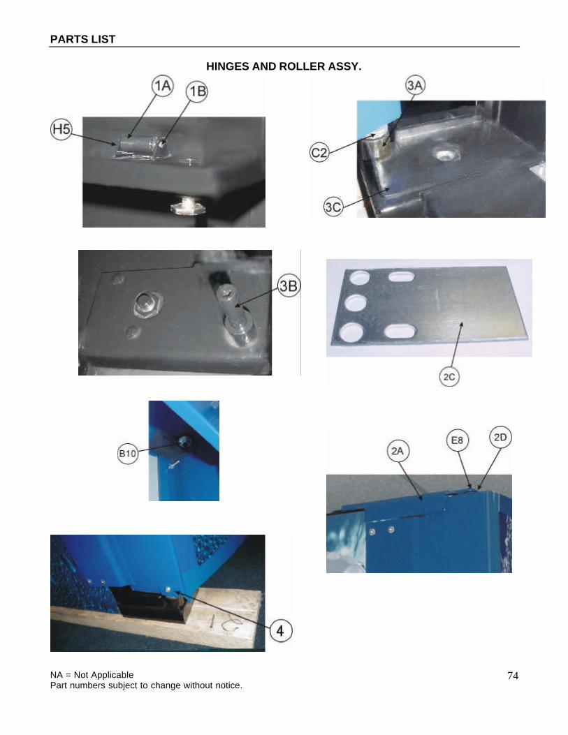
PARTS LIST
NA = Not Applicable Part numbers subject to change without notice.
74
HINGES AND ROLLER ASSY.

PARTS LIST
NA = Not Applicable Part numbers subject to change without notice.
75
HINGES AND ROLLER ASSY.
ITEM DESCRIPTION HT3 (276E) HT2 (501E) HT3 (501E) HT3 (600E) 1A Roller, Main Door All Styles 901,806,20x.x1 901,806,20x.x1 901,806,20x.x1 901,806,20x.x1 1B Roller Pin All Styles 900,502,19x.x1 900,502,19x.x1 900,502,19x.x1 900,502,19x.x1 2A Assy., Top Hinge (drop in pin) E-Models All Styles Pepsi 631,062,00x.x3 609,051,40x.x3 609,051,40x.x3 609,051,40x.x3 All Styles Mtn. Dew 631,055,40x.x3 NA 631,055,40x.x3 631,055,40x.x3 2B Top Hinge (drop in pin) E-Models All Styles 801,304,92x.x1 801,304,92x.x1 801,304,92x.x1 801,304,92x.x1 2C Top Hinge Spacer All Styles 169,000,15x.x3 169,000,15x.x3 169,000,15x.x3 169,000,15x.x3 2D Bearing Sleeve All Styles 805,300,42x.x1 805,300,42x.x1 805,300,42x.x1 805,300,42x.x1 3A Bottom Hinge Sleeve All Styles 900,502,64x.x1 900,502,64x.x1 900,502,64x.x1 900,502,64x.x1 3B Bottom Hinge Pin Pepsi 900,502,70x.x1 900,502,70x.x1 900,502,70x.x1 900,502,70x.x1 3C Bottom Hinge Assy. Cabinet Pepsi 801,305,07x.x1 801,304,90x.x1 801,305,07x.x1 801,305,07x.x1 4A Door Stop Pepsi 631,001,43x.x3 NA 631,001,43x.x3 631,001,43x.x3 Door Stop Mtn. Dew 631,050,42x.x3 NA 631,050,42x.x3 631,050,42x.x3 4B Door Stop Bracket Pepsi 592,051,19x.x3 NA 592,051,19x.x3 592,051,19x.x3 Door Stop Bracket Mtn. Dew 631,050,41x.x3 NA 631,050,41x.x3 631,050,41x.x3 A9 Screw, Phil Pan Swage Form #8-32x3/8" 900,301,56x.x1 900,301,56x.x1 900,301,56x.x1 900,301,56x.x1 A15 Screw, Machine Truss #10-32x1/2" 900,201,14x.x1 900,201,14x.x1 900,201,14x.x1 900,201,14x.x1 A17 Screw, Self Tapping 1/4-20x5/8" 900,302,01x.x1 900,302,01x.x1 900,302,01x.x1 900,302,01x.x1 B2 Keps Nut, 1/4-20 900,800,67x.x1 900,800,67x.x1 900,800,67x.x1 900,800,67x.x1 B4 Keps Nut, Top Door Hinge 3/8-16 900,800,69x.x1 900,800,69x.x1 900,800,69x.x1 900,800,69x.x1
B10 Hex Nut, 5/16-28 Center w/Flange (top hinge - drop in) 900,801,02x.x1 900,801,02x.x1 900,801,02x.x1 900,801,02x.x1
C2 Flat Washer Door Hinge (Bottom) 901,303,77x.x1 901,303,77x.x1 901,303,77x.x1 901,303,77x.x1 C10 Washer, Flat 18 Gauge 900,700,83x.x1 900,700,83x.x1 900,700,83x.x1 900,700,83x.x1 C11 Flat Washer, 14 Gauge 5/16"-3/8"x7/8" 900,700,08x.x1 900,700,08x.x1 900,700,08x.x1 900,700,08x.x1 E2 Carriage Bolt, 1/4-20x1 (Top Hinge) NA 900,201,17x.x1 NA NA E6 Carriage Bolt 1/4-20x3/4" 900,201,56x.x1 900,201,56x.x1 900,201,56x.x1 900,201,56x.x1
E8 Carriage Bolt, 1/4-20x1 1/4 (top hinge - drop in) 900,201,85x.x1 900,201,85x.x1 900,201,85x.x1 900,201,85x.x1
E9 Carriage Bolt, 1/4-20x5/8" 800,303,19x.x1 800,303,19x.x1 800,303,19x.x1 800,303,19x.x1 Carriage Bolt, 1/4-20x1 1/4 (top hinge) 900,201,23x.x1 NA 900,201,23x.x1 900,201,23x.x1 H5 Retainer, Roller Pin 900,900,90x.x1 900,900,90x.x1 900,900,90x.x1 900,900,90x.x1

PARTS LIST
NA = Not Applicable Part numbers subject to change without notice.
76
REFRIGERATION SYSTEM
(SECTION ONE)

PARTS LIST
NA = Not Applicable Part numbers subject to change without notice.
77
REFRIGERATION SYSTEM (SECTION ONE)
ITEM DESCRIPTION HT2 (501E) HT3 (276E/501E/600E) 1 Complete Refrigeration System *Domestic 1203ft C-E 115/60 prior to 0401-6917 609,046,20x.x4 609,046,20x.x4 *Domestic 3001 C-E 115/60 0401-6917 & higher 609,047,10x.x4 609,047,10x.x4 1/3 HP 220-240/50 "E" (1222B-E IEC) 609,040,20x.x3 609,040,20x.x3 1/3 HP 220-240/50 "E" (1222B-E AUS) 609,040,30x.x3 609,040,30x.x3 1/3 HP 220-240/50 "E" (1222B-E GEN) 609,040,40x.x3 609,040,40x.x3 2A Compressor *FFI12HBX 115/60 1/3 HP (for 1203ft) 802,501,74x.x1 802,501,74x.x1 *FFI12HBX 115/60 1/3 HP (for 3001) NA 802,501,74x.x1 FFI12HBK 220/50 1/3 HP 802,502,17x.x1 802,502,17x.x1 2B Compressor Lead Harness (Not Shown) 115/60 (1202CB-E) 904,900,61x.x1 904,900,61x.x1 Europe (1222B-E IEC) 804,905,32x.x1 804,905,32x.x1 IECA (1222B-E AUS) 804,904,49x.x1 804,904,49x.x1 220/50 (1222B-E GEN) 904,900,61x.x1 904,900,61x.x1 2C Compressor Mounting Grommet (Black) 902,000,57x.x1 902,000,57x.x1 2D Compressor Mounting Clip 900,901,88x.x1 900,901,88x.x1 2E Compressor Grommet Plug, Plastic 901,803,91x.x1 901,803,91x.x1 3A *Condenser Base Plate for 1203 491,040,25x.x3 491,040,25x.x3 *Condenser Base Plate for 3001 NA 639,040,02x.x3 3B Condenser Fan Motor Assy. *115/60 for 1203 491,040,20x.x3 491,040,20x.x3 *115/60 for 3001 NA TBD 220/50 491,140,30x.x3 491,140,30x.x3 3C Condenser Fan Motor Bracket (“A” Frame) *115/60 for 1203 804,500,67x.x1 804,500,67x.x1 *115/60 for 3001 NA 801,306,63x.x1 220/50 804,500,70x.x1 804,500,70x.x1 3D Condenser Fan Blade *All Styles FY870CW25S for 1203 800,103,37x.x2 800,103,37x.x2 *All Styles FV900CW30S for 3001 NA 801,306,65x.x1 4A Drain Pan Assy. w/ Fiberglass Soakers 491,000,10x.x3 805,800,71x.x1 4B Drain Pan, Plastic w/ Fingers (Not Shown) 801,804,24x.x1 801,804,24x.x1 4C Soakers, Fiberglass (14 required) 905,800,69x.x1 905,800,69x.x1 5A Ingress Guard 594,041,40x.x3 594,041,40x.x3 5B Rear Condensate Plate 801,903,52x.x1 801,903,52x.x1 6A Drain Tube 801,806,05x.x1 801,806,05x.x1 6B Drain Tube Nut 900,301,79x.x1 900,301,79x.x1 7A Drain Hose 901,900,50x.x1 901,900,50x.x1 7B Drain Hose Clamp 900,901,03x.x1 900,901,03x.x1 8 Main Wiring Harness (Detachable) United States & Mexico 804,902,22x.x1 804,917,26x.x1 9 Power Cord (Detachable) 804,917,28x.x1 804,917,28x.x1
*Exceptions : 0572 through 0580 – 6917 ; 0001 through 0286 – 6920 ; 0256 through 0270 – 6923
Use the Domestic 3001 115/60 Unit.

PARTS LIST
NA = Not Applicable Part numbers subject to change without notice.
78
REFRIGERATION SYSTEM (SECTION TWO)

PARTS LIST
NA = Not Applicable Part numbers subject to change without notice.
79
REFRIGERATION SYSTEM (SECTION TWO)
ITEM DESCRIPTION HT2 (501E) HT3 (276E/501E/600E) 9 Fan Housing Assy. Assy., Housing Fan (Wide) 609,044,80x.x1 609,044,80x.x1 Assy, Fan Evaporator Energy Star 0197-6978CC & higher N/A 646,040,40x.x3 10 Temperature Sensor (Encapsulated) 804,919,35x.x1 804,919,35x.x1 10A Temp Sensor Harness 804,917,41x.x1 804,917,41x.x1 10B Cover, Temp Sensor HVV 631,001,42x.x3 631,001,42x.x3 11 *Condenser Fan Shroud for 1203 491,040,11x.x3 491,040,11x.x3 *Condenser Fan Shroud for 3001 NA 640,040,02x.x3 12 Overload – Relay Cover Assy. Domestic 802,501,77x.x1 802,501,77x.x1 12A Relay Domestic Models Embraco 1.351.605 802,502,13x.x1 802,502,13x.x1 12B Overload Domestic Models 802,502,10x.x1 802,502,10x.x1 12C Cover 802,501,86x.x1 802,501,86x.x1 13 Dryer .054 Outlet 4AXH7 802,401,29x.x1 802,401,29x.x1 14 Condenser *3 FPI for 1203 802,600,68x.x1 802,600,68x.x1 *1.3 FPI for 3001 NA 802,600,69x.x1 15 Evaporator (short) CW01655 (1/3 HP) 802,600,37x.x1 802,600,37x.x1 16 Accumulator 1/3 HP 802,400,46x.x1 802,400,46x.x1 17 Capacitor, Start Domestic, 233-280MFD / 115V 60 Hz (FOR 1/3 HP) 802,501,21x.x1 802,501,21x.x1 17A Capacitor, End Cap Bottom Hole (Not Shown) Domestic 802,501,18x.x1 802,501,18x.x1 17B Capacitor Assembling Bracket (Not Shown) Domestic 802,501,87x.x1 802,501,87x.x1 18 Cover, Embraco (Not Shown) x.x5x.x04 Short (Domestic) – 1/3 HP 802,501,86x.x1 802,501,86x.x1 x.x5x.x00 Long (220/50) – 1/3 HP 802,501,95x.x1 802,501,95x.x1 19 Top Evaporator Cover 609,050,06x.x3 609,050,51x.x3 20 Temp Control Plate NA 491,070,08x.x3 21 GE Temp Control NA 802,800,58x.x1 22 Silencer 902,100,29x.x1 902,100,29x.x1 23 Choke Energy Star 0197-6978CC & high NA 804,920,41x.x1
*Exceptions : 0572 through 0580 – 6917 ; 0001 through 0286 – 6920 ; 0256 through 0270 – 6923
Use the Domestic 3001 115/60 Unit.
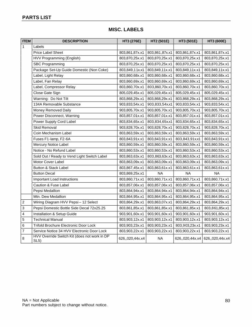
PARTS LIST
NA = Not Applicable Part numbers subject to change without notice.
80
MISC. LABELS
ITEM DESCRIPTION HT3 (276E) HT2 (501E) HT3 (501E) HT3 (600E) 1 Labels
Price Label Sheet 803,861,87x.x1 803,861,87x.x1 803,861,87x.x1 803,861,87x.x1 HVV Programming (English) 803,870,25x.x1 803,870,25x.x1 803,870,25x.x1 803,870,25x.x1
SBC Programming 803,870,25x.x1 803,870,25x.x1 803,870,25x.x1 803,870,25x.x1
Package Set-Up Guide Domestic (Non Coke) 803,849,11x.x1 803,849,11x.x1 803,849,11x.x1 803,849,11x.x1 Label, Light Relay 803,860,68x.x1 803,860,68x.x1 803,860,68x.x1 803,860,68x.x1
Label, Fan Relay 803,860,69x.x1 803,860,69x.x1 803,860,69x.x1 803,860,69x.x1 Label, Compressor Relay 803,860,70x.x1 803,860,70x.x1 803,860,70x.x1 803,860,70x.x1
Close Gate Sign 805,029,45x.x1 805,029,45x.x1 805,029,45x.x1 805,029,45x.x1
Warning: Do Not Tilt 803,868,29x.x1 803,868,29x.x1 803,868,29x.x1 803,868,29x.x1 134A Removable Substance 903,833,54x.x1 903,833,54x.x1 903,833,54x.x1 903,833,54x.x1
Money Removed Daily 903,805,70x.x1 903,805,70x.x1 903,805,70x.x1 903,805,70x.x1 Power Disconnect, Warning 803,857,01x.x1 803,857,01x.x1 803,857,01x.x1 803,857,01x.x1
Power Supply Cord Label 803,834,65x.x1 803,834,65x.x1 803,834,65x.x1 803,834,65x.x1
Skid Removal 903,828,70x.x1 903,828,70x.x1 903,828,70x.x1 903,828,70x.x1 Coin Mechanism Label 803,863,59x.x1 803,863,59x.x1 803,863,59x.x1 803,863,59x.x1
Fuses F1-lamp, F2-6A 803,843,91x.x1 803,843,91x.x1 803,843,91x.x1 803,843,91x.x1 Mercury Notice Label 803,860,59x.x1 803,860,59x.x1 803,860,59x.x1 803,860,59x.x1
Notice - No Refund Label 803,860,53x.x1 803,860,53x.x1 803,860,53x.x1 803,860,53x.x1
Sold Out / Ready to Vend Light Switch Label 803,863,63x.x1 803,863,63x.x1 803,863,63x.x1 803,863,63x.x1 Motor Cover Label 803,863,09x.x1 803,863,09x.x1 803,863,09x.x1 803,863,09x.x1
Button & Stack Label 803,867,45x.x1 803,863,61x.x1 803,863,61x.x1 803,863,61x.x1 Button Decal 803,869,25x.x1 NA NA NA
Important Load Instructions 803,860,71x.x1 803,860,71x.x1 803,860,71x.x1 803,860,71x.x1
Caution & Fuse Label 803,857,06x.x1 803,857,06x.x1 803,857,06x.x1 803,857,06x.x1 Pepsi Medallion 803,864,94x.x1 803,864,94x.x1 803,864,94x.x1 803,864,94x.x1
Mtn. Dew Medallion 803,864,95x.x1 803,864,95x.x1 803,864,95x.x1 803,864,95x.x1 2 Wiring Diagram HVV Pepsi – 12 Select 803,864,29x.x1 803,863,07x.x1 803,864,29x.x1 803,864,29x.x1
3 Pepsi Domestic Bottle Side Decal 72x25.25 803,861,85x.x1 803,861,85x.x1 803,861,85x.x1 803,861,85x.x1
4 Installation & Setup Guide 903,901,60x.x1 903,901,60x.x1 903,901,60x.x1 903,901,60x.x1 5 Technical Manual 803,903,12x.x1 803,903,12x.x1 803,903,12x.x1 803,903,12x.x1
6 Trifold Brochure Electronic Door Lock 803,903,23x.x1 803,903,23x.x1 803,903,23x.x1 803,903,23x.x1 7 Service Notice 34 HVV Electronic Door Lock 803,903,22x.x1 803,903,22x.x1 803,903,22x.x1 803,903,22x.x1
8 HVV Override Switch Kit (does not work in DP SL5) 626,,020,44x.x4 NA 626,,020,44x.x4 626,,020,44x.x4
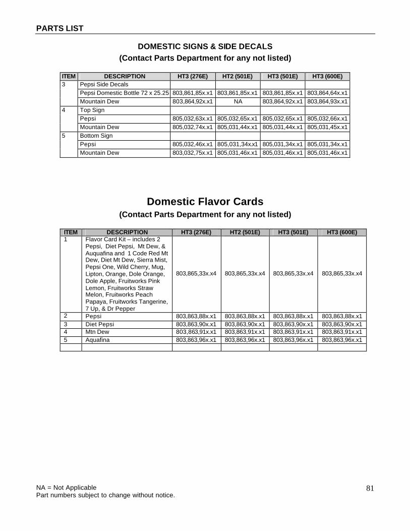
PARTS LIST
NA = Not Applicable Part numbers subject to change without notice.
81
DOMESTIC SIGNS & SIDE DECALS (Contact Parts Department for any not listed)
ITEM DESCRIPTION HT3 (276E) HT2 (501E) HT3 (501E) HT3 (600E) 3 Pepsi Side Decals Pepsi Domestic Bottle 72 x 25.25 803,861,85x.x1 803,861,85x.x1 803,861,85x.x1 803,864,64x.x1 Mountain Dew 803,864,92x.x1 NA 803,864,92x.x1 803,864,93x.x1 4 Top Sign Pepsi 805,032,63x.x1 805,032,65x.x1 805,032,65x.x1 805,032,66x.x1 Mountain Dew 805,032,74x.x1 805,031,44x.x1 805,031,44x.x1 805,031,45x.x1 5 Bottom Sign Pepsi 805,032,46x.x1 805,031,34x.x1 805,031,34x.x1 805,031,34x.x1 Mountain Dew 803,032,75x.x1 805,031,46x.x1 805,031,46x.x1 805,031,46x.x1
Domestic Flavor Cards (Contact Parts Department for any not listed)
ITEM DESCRIPTION HT3 (276E) HT2 (501E) HT3 (501E) HT3 (600E) 1 Flavor Card Kit – includes 2
Pepsi, Diet Pepsi, Mt Dew, & Auquafina and 1 Code Red Mt Dew, Diet Mt Dew, Sierra Mist, Pepsi One, Wild Cherry, Mug, Lipton, Orange, Dole Orange, Dole Apple, Fruitworks Pink Lemon, Fruitworks Straw Melon, Fruitworks Peach Papaya, Fruitworks Tangerine, 7 Up, & Dr Pepper
803,865,33x.x4 803,865,33x.x4 803,865,33x.x4 803,865,33x.x4
2 Pepsi 803,863,88x.x1 803,863,88x.x1 803,863,88x.x1 803,863,88x.x1 3 Diet Pepsi 803,863,90x.x1 803,863,90x.x1 803,863,90x.x1 803,863,90x.x1 4 Mtn Dew 803,863,91x.x1 803,863,91x.x1 803,863,91x.x1 803,863,91x.x1 5 Aquafina 803,863,96x.x1 803,863,96x.x1 803,863,96x.x1 803,863,96x.x1
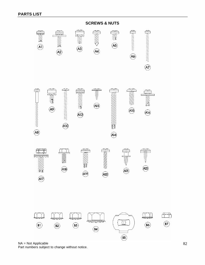
PARTS LIST
NA = Not Applicable Part numbers subject to change without notice.
82
SCREWS & NUTS

PARTS LIST
NA = Not Applicable Part numbers subject to change without notice.
83
SCREWS & NUTS ITEM PART NUMBER PART NAME AND DESCRIPTION
A1 900,301,70x.x1 Screw, Phil Pan Swage Form #6 - 32 x 3/8" A2 900,301,64x.x1 Screw, Phil Pan Swage Form w/washer #8 - 32 x 1/2" A3 900,301,83x.x1 Screw, Phil Pan Swage Form #10 - 32 x 5/16" A4 900,301,50x.x1 Screw, Phil Pan w/out washer, #8 - 18 x 1/2" A5 900,301,97x.x1 Screw, Phil Pan Swage Form #8 - 32 x 1/4" A6 900,300,47x.x1 Screw, Vend Motor, #4-24 x 3/4" Single Switch (NOT USED) A7 900,301,82x.x1 Screw, Vend Motor, #4-24 x 1 1/16" Double Switch (NOT USED) A8 900,301,61x.x1 Screw, Vend Motor, #4-24 x 1 1/2" Triple Switch (NOT USED) A9 900,301,56x.x1 Screw, Phil Pan Cutting #8 - 32 x 3/8" A10 900,201,31x.x1 Screw, Machine, #6 - 32 x 1 1/4" A11 900,301,97x.x1 Screw, Phil Pan Sems #8 - 32 x 1/4" A12 900,301,85x.x1 Screw, Phil Thread Form #8 - 32 x 5/8" A13 900,300,16x.x1 Screw, Phil Head Truss #6 x 3/8" A14 900,301,81x.x1 Screw, Phil Pan Form #10 - 32 x 1 1/4" A15 900,201,14x.x1 Screw, Machine Truss, #10 - 32 x 1/2" A16 900,301,65x.x1 Screw, Phil Pan Sems with washer, #8 - 18 x 1/2" A17 900,302,01x.x1 Screw, Self Tapping, 1/4 - 20 x 5/8" A18 900,301,69x.x1 Screw, Hex Head Swage Form #8 - 36 x 3/8" A19 900,901,51x.x1 Screw, Phil Pan Tapping #10 - 32 x 5/8" A20 900,201,22x.x1 Screw, Machine Phil Pan #8 - 32 x 3/4" A21 900,301,98x.x1 Screw, Phil Pan Shoulder #8 - 18 x 1/2" A22 900,301,84x.x1 Screw, Phil Pan #8-18x1/2" A23 900,500,26x.x1 Shoulder Screw 1/2" Long A24 900,201,13x.x1 Screw, Hex Head A25 900,301,73x.x1 Screw, Tap 1/4-20x1" Type F A26 800,303,15x.x1 Screw, Phil Pan #8-18x3/4" A27 800,303,18x.x1 Screw, Truss Type 23 #8-32x1/2 A28 900,301,94x.x1 Screw, Phil Flat 23B #10-32x1/2" A29 900,201,44x.x1 Screw, Machine Brass #6-32x1/4" A30 900,301,99x.x1 Screw, Plastic 8-hi/low x 1 1/4 A31 900,301,55x.x1 Screw, Phil Pan Swage Form #8-32x1/2" A32 900,303,08x.x1 Screw, Hex Washer Type 1 #8-32x3/8" A34 800,303,22x.x1 Screw, Phil Pan #6-20x3/8 A35 900,302,02x.x1 Screw, Self Tapping, #8-18x3/4 A36 900,201,86x.x1 Screw, Phil Pan Head #6-32x1/4" B1 900,800,65x.x1 Keps Nut, #10 - 32 B2 900,800,67x.x1 Keps Nut, 1/4 - 20 B3 900,800,50x.x1 Keps Nut, #8 - 32 B4 900,800,69x.x1 Keps Nut, Top Door Hinge, 3/8 - 16 B5 900,800,85x.x1 Speed Nut B6 900,800,49x.x1 Keps Nut, #6 - 32 B7 900,800,51x.x1 Elastic Stop Nut, #8 - 32 B8 900,800,81x.x1 Hex Nut 8-32 B9 900,902,37x.x1 Push Nut, Acorn Type B10 900,801,02x.x1 Hex Nut 5/16-18 B11 900,800,81x.x1 Hex Nut, Flange with Serrations 8-32

PARTS LIST
NA = Not Applicable Part numbers subject to change without notice.
84
WASHERS, BOLTS, & MISC. HARDWARE

PARTS LIST
NA = Not Applicable Part numbers subject to change without notice.
85
WASHERS, BOLTS, & MISC. HARDWARE
ITEM PART NUMBER PART NAME AND DESCRIPTION C1 900,700,60x.x1 Washer, Delrin .047 Thick 3/8"IDx5/8"OD C2 901,303,77x.x1 Washer, Door Hinge C3 901,503,06x.x1 Washer, Flat #2949 (T-Handle) C4 901,503,08x.x1 Washer, Hex #29-34 (T-Handle) C5 900,700,36x.x1 Lockwasher, Split 3/8" C6 900,700,89x.x1 Lockwasher, Shakeproof 5/8" (1132-00-00-0551) C7 900,700,02x.x1 Steel Washer, 18 Gauge (1/2"x3/16") C8 900,700,62x.x1 Washer, Shakeproof (4610-16-01-0551) C10 900,700,83x.x1 Washer, Flat 18 Gauge (17/64""IDx5/8"OD) C11 900,700,08x.x1 Washer, Flat 14 Gauge (5/16"-3/8"x7/8") C12 801,902,48x.x1 Nylon Spacer 900,701,05x.x1 Washer Flat (.343"ID x .688" OD .6T) D1 900,400,43x.x1 T-Bolt, #8 - 32 x 1" (obsolete) D2 900,400,41x.x1 T-Bolt, #8 - 32 x 1 3/8" D3 900,40x.x5x.x1 T-Bolt, #8 - 32 x 3/4" D4 900,400,45x.x1 T-Bolt, #8 - 32 x 1/2" E1 900,400,44x.x1 Refrigeration Bolt, 3/8 - 16 x 1" E2 900,201,17x.x1 Carriage Bolt, 1/4 - 20 x 1" E3 900,201,23x.x1 Carriage Bolt, 1/4 - 20 x 1 1/4" E4 900,201,45x.x1 Carriage Bolt, 1/4 - 20 x 1/2" E5 900,201,54x.x1 Carriage Bolt, 1/4 - 20 x 3/8" E6 900,201,56x.x1 Carriage Bolt, 1/4 - 20 x 3/4" E7 900,303,12x.x1 Carriage Bolt, 1/4-20x5/8" (obsolete) E8 900,201,85x.x1 Carriage Bolt, 5/16x18x1 1/4" Top Hinge (drop in) E9 800,303,19x.x1 Carriage Bolt, 1/4-20x5/8" E10 900,202,04x.x1 Carriage Bolt, ¼-20x1/2” (red) F1 901,100,43x.x1 Pop Rivet, Aluminum 1/4" F2 901,100,44x.x1 Drive Rivet, #38-108-06-13 1/4" dia. F4 901,100,54x.x1 Pop Rivet, Black 1/8" F5 901,100,61x.x1 Pop Rivet, Steel (Zinc Plated) 1/8" F6 901,100,53x.x1 Pop Rivet, Aluminum 1/8" F7 901,100,60x.x1 Pop Rivet, Steel (Zinc Plated) 3/16" H1 900,902,13x.x1 Christmas Tree Clip #354280307-00 (NOT USED) H2 900,901,89x.x1 Tinnerman Clip, Fan Shroud (C5207-014-3B) H3 900,401,09x.x1 Grommet, Bk. Rubber #97 H4 901,503,07x.x1 E-Ring #31-30 H5 900,900,90x.x1 Retainer, Roller Pin H6 900,902,18x.x1 Tinnerman Clip H7 801,807,01x.x1 Hole Plug, Snap in - 1 1/4 H8 901,806,77x.x1 Grommet, Admiral #B53351 H9 902,100,29x.x1 Silencer I1 804,601,45x.x1 #6 Terminal Ring Crimp 16-14 AWG I2 801,902,48x.x1 Nylon Spacer used on Coke D/O Boards I3 801,809,12x.x1 Velcro Blocks I4 801,807,49x.x1 Vender Defender Clamp

PARTS LIST
NA = Not Applicable Part numbers subject to change without notice.
86
WASHERS, BOLTS, & MISC. HARDWARE
ITEM PART NUMBER PART NAME AND DESCRIPTION I5 901,901,89x.x1 Clamp, Cable 1" Heyco 3390 I6 900,901,79x.x1 Clamp, Nylon 5/16" Black Heyco 3355 or Dennison 10159 I7 900,901,80x.x1 Clamp, Nylon 1/2" Heyco 3328 I8 901,901,06x.x1 Hand Tie, x.x" I9 901,902,01x.x1 Wire Tie, 7 1/2" I10 901,901,00x.x1 Wire Ties, 4" I11 901,900,55x.x1 Clamp, Nylon 3/4" Heyco 3382BL I12 901,902,83x.x1 Cable Tie, x.x" I13 900,902,14x.x1 Canoe Clip #254-090-301-00-0108
ELECTRONICS & COMPONENTS
ITEM PART NAME AND DESCRIPTION HT2 (501E) HT3 (276E/501E/600E)
1 Electronic Lock Assembly 805,202,44x.x1 805,202,44x.x1 2 Electronic Lock Light Pipe 801,814,19x.x1 801,814,19x.x1 3 Machine Controller 804,918,15x.x1 NA 4 Machine Controller Base 801,813,45x.x1 NA 5 Machine Controller Cover 631,000,68x.x3 NA 6 Universal Controller 804,916,31x.x1 NA 7 Display (Vacuum Fluorescent) 804,918,69x.x1 804,918,69x.x1 8 Transformer 804,909,80x.x1 804,909,80x.x1 9 Machine Controller EPROM 804,917,61x.x1 NA 10 Universal Controller EPROM 804,917,25x.x1 NA 11 Fuse 6 Amp (F2) 804,910,93x.x1 804,910,93x.x1 12 Fuse 1.6 Amp (F1) 804,800,71x.x1 804,800,71x.x1 13 Control Board Assy. HT3 NA 631,053,30x.x3 14 HT3 Eprom Control Board NA 804,919,24x.x1 15 Override Switch Kit (does not work w/ DPSL5) 626,020,44x.x4 626,020,44x.x4 16 HVV SBC 6 mp Fuse 804,920,44x.x1 804,920,44x.x1 17 Battery 3V (CR2032) Lithium 804,920,45x.x1 804,920,45x.x1 18 Environmental Control Kit 631,004,00x.x4 631,004,00x.x4