peninsula corridor joint powers board - …cadd+manual+20… · national cad standard layer name...
TRANSCRIPT


PENINSULA CORRIDOR JOINT POWERS BOARD CADD MANUAL REVISION HISTORY
May 4, 2007
PENINSULA CORRIDOR JOINT POWERS BOARD (PCJPB) CADD MANUAL
This is a Controlled Document. Any proposed changes or updates must be submitted to PCJPB’s CADD Department Manager for consideration.
Document Revision History
Revision Date
Revision No.
Revision Summary Description
December 31, 2002 0 First Issue
November 12, 2004 1 Major rewrite. Deleted Section 5. Added Appendices 9
and 10.
May 4, 2007 2
Revisions throughout. Completely rewrote some Sections. Made additions to others. Deleted Appendix 7. Adopted National CAD Standard layer name convention. Dropped the PCJPB text style.

PENINSULA CORRIDOR JOINT POWERS BOARD CADD MANUAL
Table of Contents 05/2007
CADD Manual
TA B L E O F C O N T E N T S SECTION 1 INTRODUCTION SECTION 2 DRAWING FORMAT SECTION 3 DRAWING NUMBERS, CADD FILE NAMING SYSTEM AND DRAWING STRUCTURE SECTION 4 DRAWING BORDER AND TITLE SECTION 5 NOT USED SECTION 6 DRAWING TYPES SECTION 7 DRAFTING RULES SECTION 8 DRAWING ORGANIZATION AND DESIGN GUIDELINES SECTION 9 DRAWING DEVELOPMENT AND REVISION SECTION 10 CONTRACT DRAWING SUBMITTALS
A P P E N D I C E S APPENDIX 1 DISCIPLINE CODES APPENDIX 2 CIVIL DRAWING ORGANIZATION FOR A HYPOTHETICAL PROJECT APPENDIX 3 LAYER NAMES APPENDIX 4 PEN MAPPING APPENDIX 5 PCJPB’S AERIAL TOPOGRAPHY FILES APPENDIX 6 PCJPB LINETYPES APPENDIX 7 NOT USED APPENDIX 8 STANDARD BLOCK LIBRARY (PENDING) APPENDIX 9 METRIC DRAWINGS APPENDIX 10 PCJPB CADD REQUIREMENTS FOR SIGNAL DRAWINGS

PENINSULA CORRIDOR JOINT POWERS BOARD CADD MANUAL
Section 1 1-1 05/2007
SECTION 1 INTRODUCTION
GENERAL This Manual outlines the general drafting standards and Computer Aided Design and Drafting (CADD) requirements for the preparation of all drawings to be used in the planning, design and construction of Peninsula Corridor Joint Powers Board (PCJPB) facilities. All designers—PCJPB staff, engineering consultants, construction contractors and any other parties involved in the design and construction or oversight of PCJPB projects—should know and follow the guidelines in this Manual. Consultants shall ensure that any sub-consultants they retain for work on PCJPB projects know and adhere to the standards set forth in this Manual. The goal is uniformity and compatibility among all drawings prepared for PCJPB improvement projects. As of this writing, PCJPB uses Autodesk’s AutoCAD, version 2007. To avoid the problems often occurring when converting drawing files from one CADD software package to another, designers shall create and submit all drawing files (except signal drawings) in native AutoCAD, version 2007 or the latest PCJPB approved AutoCAD release. Autodesk’s Land Development Desktop (LDD) and/or Civil 3D, version 2007 or the latest PCJPB approved AutoCAD release shall be used to prepare civil drawings. Drawing files converted to AutoCAD from other CADD software packages will not be accepted. Signal drawings, however, are currently created and submitted in Bentley’s MicroStation. Unless directed otherwise by PCJPB’s Chief Engineer or the PCJPB CADD Manager, these standards shall be used to prepare all drawings required for PCJPB projects. The production of drawings at variance with these standards may proceed only with the approval of the PCJPB CADD Manager. This manual is a living document and is therefore subject to revision. Please bring any suggestions for improvement, errors and/or omissions to the attention of the PCJPB CADD Manager. CADD Manager PCJPB-Caltrain Engineering Department 1250 San Carlos Avenue P.O. Box 3006 San Carlos, CA 94070-1306 MANUAL DISTRIBUTION PCJPB’s CADD Manual is available in PDF format on PCJPB’s ftp site for designers and other interested parties to download.

PENINSULA CORRIDOR JOINT POWERS BOARD CADD MANUAL
Section 1 1-2 05/2007
OTHER PCJPB GUIDELINES AND STANDARDS Following is a list of other PCJPB Guidelines and Standards:
1. PCJPB Engineering Standards for Excavation Support Systems 2. PCJPB Communications/Signal Engineering Standards 3. PCJPB Track Standards 4. PCJPB Standards – Volume I and Volume II 5. PCJPB Standard Operating Procedures (SOP) for Maintenance and Construction
(includes requirements for operations after an earthquake) 6. PCJPB Station Facility Guidelines 7. PCJPB Electrification Standards 8. PCJPB Policy on High and Low Risk Underground Facilities Within the PCJPB’s
Right-of-Way BACKGROUND AND HISTORY OF CALTRAIN
A. History
Passenger service on the peninsula corridor began on Oct. 18, 1863 under the authority of the San Francisco and San Jose Railroad Company. Prophetically, some $600,000 of the original $2 million capital stock issue was owned by the voters of San Francisco, San Mateo and Santa Clara counties following a three-county election in 1861. In 1870, the San Francisco and San Jose Railroad Company was acquired by the firm that was eventually consolidated into the Southern Pacific Railway. Southern Pacific double-tracked the line in 1904, and operated passenger service in the corridor successfully until after World War II. Changing commute patterns impacted Southern Pacific along with private carriers all over the country, and after protracted struggles with the state Public Utilities Commission on fares and service levels, Southern Pacific petitioned to abandon passenger service in 1977.
The three Peninsula counties stepped into the breach with a temporary Fare Stabilization Plan -- partially subsidizing commuter tickets -- that reversed a long pattern of declining ridership and set the stage for state sponsorship of the Peninsula Commute in 1980. From 1980 until mid-year 1992, Caltrans contracted with Southern Pacific to provide passenger service in the corridor, sharing operating subsidies with San Francisco, San Mateo and Santa Clara counties. The state assumed sole responsibility for station acquisitions and other capital improvements until the service resulted in formation of the Peninsula Corridor Joint Powers Board (PCJPB) in 1987. The PCJPB agreed to assume operating responsibilities for Caltrain effective July 1, 1992, and to shoulder 100 percent of the operating subsidy a year later. In December 1991, the PCJPB purchased the rail right of way from San Francisco to San Jose. The PCJPB secured trackage rights to Gilroy for another $4 million. Union Pacific Railroad, which merged with Southern Pacific in 1996, retains rights to operate freight service along the corridor. To replace Southern Pacific as the commute operator, the PCJPB signed Amtrak, the national passenger rail corporation, to a three-year agreement with two one-year options beginning July 1, 1992. In November of 2001, Amtrak was awarded a 5-year contract to continue commute service for the PCJPB.

PENINSULA CORRIDOR JOINT POWERS BOARD CADD MANUAL
Section 1 1-3 05/2007
Contract oversight is provided by SamTrans, as the administrative arm of PCJPB. Caltrans deeded 26 stations, 20 diesel locomotives and 73 bi-level passenger cars to the PCJPB in 1993. Many of locomotives and gallery cars have been rebuilt or replaced over last five years.
B. Caltrain Fast Facts
• 77 miles of mainline track between San Francisco and Gilroy • 80 scheduled weekday trains
• 34 stations, most have parking
• 48 grade crossings between San Francisco and San Jose
• 38 grade crossings between San Jose and Gilroy
• Push / pull operation
• Top train speed of 79 miles per hour
• Each train consist can handle 24 bicycles
• Average daily ridership over 32,000 passengers
• 23 locomotives, 73 cars, including 21 cab cars
C. Caltrain Milestones
• December 2002 Awarded a $39 million construction contract for 3 projects along the Caltrain right of way. The project is known as the South CTX.
• July 2002 Temporarily discontinued train service on weekends for a 20 month period to facilitate CTX Project construction.
• April 2002 Awarded a $64 million construction contract for 6 projects along the Caltrain right of way. The project is known as the North CTX.
• November 2001 Awarded a five year contract for Operation of Commuter Rail Service and Con-struction Support Services
• March 2000 Inaugurated special service to Pacific Bell Park for San Francisco Giants baseball games.

PENINSULA CORRIDOR JOINT POWERS BOARD CADD MANUAL
Section 1 1-4 05/2007
• November 1999 Opened the new, relocated Hayward Park station in San Mateo.
• May 1999 Approved the Rapid Rail Plan, an $836 million rehabilitation electrification program.
• April 1999 Opened the San Antonio station in Mountain View. Added weekday trains, bringing the weekday total to 68.
• January 1999 Awarded a $54 million construction contract for 30 projects along the Caltrain right of way. The project is known as the Ponderosa.
• December 1998 Caltrain receives the first of three new locomotives. A celebration was held at Caltrain's Fourth and King Streets station in San Francisco to honor the completion of the interior station renovation.
• August 1998 Began selling 10-ride tickets via the internet.
• March 1998 Twenty new passenger cards ordered, six of which are cab cars. Also ordered 101 state-of-the-art ticket vending machines.
• July 1997 Caltrain increases service: six weekday trains and two Saturday trains. Caltrain also introduces a new logo.
• June 1996 Caltrain records the highest annual ridership since 1958 -- 7.4 million.
• Nov. 24, 1995 The number of bicycles allowed per train increases to 24 making Caltrain the least restrictive and most accessible rail system to bicyclists in the country.
• July 1995 Caltrain becomes accessible to passengers in wheelchairs. The Redwood City Transit Center, serving Caltrain and SamTrans bus passengers, is dedicated.
• Dec. 8, 1994 Dedication ceremony is held to mark the completion of the reconstruction and restoration of the San Jose terminal, which is renamed "San Jose Diridon Station."
• Sept. 17, 1994 Burlingame station marks 100th anniversary with a community fair.

PENINSULA CORRIDOR JOINT POWERS BOARD CADD MANUAL
Section 1 1-5 05/2007
• June-July 1994 Some 170,000 people take Caltrain to and from World Cup soccer games at Stanford University.
• January 15-16, 1994 Peninsula Corridor Joint Powers Board celebrates 130 years of continuous passenger service between San Francisco and San Jose at an open house marking the 130th anniversary of the Santa Clara depot. It is the oldest continuously operating train station in California.
• September 1992 Bicycles are allowed on Caltrain under a pilot program.
• July 1, 1992 The Peninsula Corridor Study Joint Powers Board becomes the Peninsula Corridor Joint Powers Board with Amtrak as contract operator. San Mateo County Transit District provides administration and contract oversight. Weekday service is increased from 54 to 60 trains. Tamien station opens in San Jose. Service is extended to Gilroy.
• December 1991 The Joint Powers Board purchased rail lines in San Mateo and Santa Clara counties. The JPB secured trackage rights to Gilroy for another $4 million, with an option to acquire half the right of way in the future. Union Pacific retains rights to operate freight service in the corridor. Right of way is purchased from Southern Pacific Transportation Company for $220 million.
• 1988 San Carlos station celebrates its centennial. Two additional locomotives and ten more cars are purchased.
• 1987 Peninsula Corridor Study Joint Powers Board is formed.
• June 1985 The first of 63 new gallery cars equipped for push-pull operation go into service, along with 18 new F40PH diesel-electric locomotives (each named after a city on the line).
• October 1981 Train schedules are extensively modified and several "reverse commute" trains are added. Total number of weekday trains increases from 44 to 46.

PENINSULA CORRIDOR JOINT POWERS BOARD CADD MANUAL
Section 1 1-6 05/2007
• July 1, 1980 The new agreement takes effect, with Caltrans assuming responsibility for the Peninsula Commute Service.
• 1979 The 1909 wood-frame/stucco Redwood City station is damaged in a fire and replaced by a trailer.
• 1977 Southern Pacific petitions the state Public Utilities Commission (which says "no") and then the Interstate Commerce Commission to discontinue the Peninsula Commute Service. A bitter fight follows. After long months of negotiation, the three counties through which the Peninsula Commute Service runs and the California Department of Transportation (Caltrans), reach an agreement with Southern Pacific. SP would become the contractor and the public agencies would cover most of the operating costs.
• 1976 San Mateo's old station is torn down to make way for a parking structure.
• June 23, 1975 Fourth and Townsend Streets terminal opens in San Francisco.
• May 1, 1971 Amtrak takes over operation of the nation's intercity passenger trains. The northern terminal of the Coast Daylight to Los Angeles is changed to Oakland from San Francisco. Southern Pacific's Del Monte, which ran from San Francisco to Monterey, is discontinued. As a result, commuter trains become the only rail passenger service between San Francisco and San Jose.
• 1965 The grade separation is built at Hillsdale Boulevard in San Mateo.
• June 1955 The first of ten "gallery cars" are delivered to Southern Pacific. The cars, which provide more seating, are an instant success, and in January 1956, Southern Pacific orders 21 more. A final order of 15 is placed in 1968.
• Early 1950's Diesel locomotives begin to appear in the Peninsula Commute Service.
• December 1935 A new terminal opens on Cahill Street in San Jose.
• 1915 San Francisco terminal moves to Third and Townsend streets. The station has been built to handle crowds for the Panama Pacific International Exposition.
• 1870 San Francisco and San Jose Railroad is absorbed into Southern Pacific.

PENINSULA CORRIDOR JOINT POWERS BOARD CADD MANUAL
Section 1 1-7 05/2007
• Jan. 16, 1864 The line is completed to San Jose. Within a short time, two trains operate each way weekdays between San Francisco and San Jose. The San Francisco terminal initially is located at 18th and Valencia streets.
• October 1863 Regular service between San Francisco and Mayfield (now California Avenue in Palo Alto) begins. The trip takes two hours. At Mayfield, passengers have to board a stagecoach to get to San Jose.
• 1860 San Francisco and San Jose Railroad incorporates. Financing for a railroad between those cities comes from three counties -- San Francisco, San Mateo and Santa Clara.
• January 1851 A line connecting the trading center of San Francisco with California's first state capital, San Jose, was proposed.
D. Caltrain Improvements
PCJPB has a very aggressive capital improvement plan to upgrade and improve the physical plant. The plan will upgrade the route to a modern facility with continuous welded rail, new concrete and wood ties, CTC signaling and many other improvements to the stations, bridges and right of way. The annual capital expenditure is approximately $100 million. The plan calls for major capacity expansion with additional main tracks, additional and improved grade separations, improved station and terminal facilities, a new equipment maintenance facility and potential extensions. Caltrain is also planning for electrification of the route. Additionally, the Caltrain corridor and tracks may be incorporated into the future California high-speed rail system.
CALTRAIN ORGANIZATION
A. PCJPB
The Peninsula Corridor Joint Powers Board is a state-authorized joint powers authority controlled by the three counties where Caltrain operates—San Francisco, San Mateo, and Santa Clara Counties. For administrative purposes, San Mateo County’s transportation agency, SamTrans, provides administrative and staff support for PCJPB. The PCJPB has a relatively small staff and performs much of its engineering, construction, maintenance and operations with the assistance of consultants and contractors.
B. Contract Operator (Amtrak)
The contract operator (Amtrak) operates, maintains, and dispatches PCJPB trains and performs basic track, signal, and structure inspection and maintenance. Amtrak supports the substantial amount of construction and third-party work along the corridor,

PENINSULA CORRIDOR JOINT POWERS BOARD CADD MANUAL
Section 1 1-8 05/2007
primarily by providing flagging and watchmen. Amtrak also performs small construction tasks such as rebuilding yard tracks and replacing road crossings. PCJPB in conjunction with the contract operator is responsible for coordinating these activities.
C. PCJPB Construction Contractors
PCJPB construction contractors perform a wide variety of tasks, including renewals such as track, bridge, station and signal construction and reconstruction.
D. Union Pacific Joint Facilities
The Union Pacific Railroad (UPRR) operates local freight service on PCJPB trackage, and has joint facility arrangements in a number of other locations. In general, the UPRR owns and maintains Track No. 1 from CP Coast to CP Lick and all freight tracks off the main tracks from San Francisco to Lick.
E N D O F S E C T I O N 1

PENINSULA CORRIDOR JOINT POWERS BOARD CADD MANUAL
Section 2 2-i 05/2007
SECTION 2 DRAWING FORMAT
CONTENTS
PART TITLE PAGE ______________________________________________________________________ 2.1 SIZE 2-1
2.2 PROTOTYPE FILES 2-1
2.3 DRAWING TYPES 2-1
2.4 REFERENCE SYSTEMS 2-2
TABLES
2.1 SELECTED ANSI SHEET SIZES 2-1 2.1 PROTOTYPE FILES 2-3

PENINSULA CORRIDOR JOINT POWERS BOARD CADD MANUAL
Section 2 2-1 05/2007
SECTION 2 DRAWING FORMAT
2.1 SIZE
If required, submitted drawings shall be plotted on American National Standard Institute (ANSI) D size sheets. Generally, however, drawings shall be reduced (usually to half-size) and plotted on ANSI B size sheets for submittal. Standard English drawing sizes differing from the following will be used only to satisfy specific PCJPB or other agency requests.
Size Dimensions (inches)
A 8.5 x 11
B 11 x 17
C 17 x 22
D 22 x 34
TABLE 2.1 - SELECTED ANSI SHEET SIZES
2.2 PROTOTYPE FILES
To facilitate drawing creation, PCJPB has created a number of prototype files with border and title block inserted and AutoCAD drawing variables and layers set in accordance with the criteria given in this Manual. Contract drawing files may be created using these files. See Table 2.2. These files are available for downloading on PCJPB’s ftp site.
2.3 DRAWING TYPES
2.3.1 Dimensional
Dimensional drawings depict objects to scale and portray accurately the spatial relationships between them. Examples might include structural steel details, architectural elevations, track routing and layout plans, plans and profiles of storm sewers, etc. These drawings shall be prepared from AutoCAD models created at full size. Scale shall be indicated on dimensional drawings in accordance with Sections 4 and 7.
2.3.2 Non-dimensional
Non-dimensional drawings are not drawn to any scale. They portray relationships schematically or contain purely tabular or textual information. Examples include flow diagrams, electrical single line diagrams, drawing indices, etc.

PENINSULA CORRIDOR JOINT POWERS BOARD CADD MANUAL
Section 2 2-2 05/2007
2.3.3 Track Charts
Track Charts diagram the various rail alignments within the PCJPB system. Straight lines represent the alignments with distances along them shown to a set scale, which is true only along these lines. The charts show station and alignment information, such as boarding platform types, station amenities, curve data, speed limits, grades, rail type and weight, etc. Features shown crossing the alignments have an associated milepost location and provide useful reference points when locating various work areas within the PCJPB system.
2.4 REFERENCE SYSTEMS
Building an effective CADD model requires the positioning of all design elements---stations, track alignments, parking structures, column layouts, storage and maintenance yards, etc.---in the model at locations which correspond to their intended locations in the PCJPB system when finally constructed. When the design effort is complete it should be possible to overlay every plan file and view the entire design with all model elements shown in correct relationship and position. AutoCAD models showing proposed and/or existing track alignments, buildings, roadways, parking areas and/or other major installations to scale shall be positioned horizontally with reference to the California State Plane Coordinate System, Zone 3, North American Datum, 1983 (NAD83). Elevations shall be referenced to the North American Vertical Datum, 1988 (NAVD88).

PENINSULA CORRIDOR JOINT POWERS BOARD CADD MANUAL
Section 2 2-3 05/2007
Drawing Type File
Architectural ARCH.DWG
Civil CIVL.DWG
Communications COMM.DWG
Electrical ELEC.DWG
Fire Protection FPRT.DWG
General GENL.DWG
Geotechnical GEOT.DWG
Index of Drawings INDX.DWG
Landscape LAND.DWG
Mechanical MECH.DWG
Overhead Contact System EOCS.DWG
Plumbing PLMB.DWG
Structural STRU.DWG
System General SYSG.DWG
Track Work TRAK.DWG
Traction Power TPWR.DWG
Utilities UTIL.DWG
TABLE 2.2 - PCJPB’S PROTOTYPE CADD FILES
E N D O F S E C T I O N 2

PENINSULA CORRIDOR JOINT POWERS BOARD CADD MANUAL
Section 3 3-i 05/2007
SECTION 3 DRAWING NUMBERS, CADD FILE NAMING
SYSTEM AND DRAWING STRUCTURE
CONTENTS PART TITLE PAGE ______________________________________________________________________ 3.1 GENERAL 3-1
3.2 DRAWING NUMBERS 3-1
3.3 CADD FILE NAMING SYSTEM 3-1
3.4 REFERENCE FILES 3-2
3.5 DRAWING LAYERS 3-3
3.6 ENTITY COLOR 3-3
3.7 LINE WORK 3-3
3.8 TEXT 3-4
3.9 SYMBOLS AND BLOCKS 3-5
3.10 PLOTTING 3-5
FIGURES
3.1 TEXT SPECIFICATIONS 3-6
3.2 TEXT ORIENTATION 3-7
3.3 PROPERTIES DIALOG BOX WITH REVISION INFORMATION FOR A TYPICAL REFERENCE FILE 3-8
TABLES
3.1 SELECTED SCALES, SCALE FACTORS AND TEXT HEIGHTS 3-9
3.2 SELECTED SCALES, SCALE FACTORS AND TEXT HEIGHTS (CONTINUED) 3-10

PENINSULA CORRIDOR JOINT POWERS BOARD CADD MANUAL
Section 3 3-1 05/2007
SECTION 3 DRAWING NUMBERS, CADD FILE NAMING
SYSTEM AND DRAWING STRUCTURE
3.1 GENERAL
In this manual, the terms drawing and sheet refer to either a plot on paper of a layout in an AutoCAD drawing file or the layout itself. All project CADD files and plotted drawings submitted to PCJPB shall follow the naming conventions given in this Section. When creating scaled drawings, all AutoCAD entities depicting the elements of a design shall be drawn at a scale of one to one in model space. Drawings to be plotted from AutoCAD drawing files shall be created using layouts. There shall be a layout for each drawing, and each layout shall be named with the name of the drawing in the plot set it represents. For example, layout C101 would correspond with drawing C101 in the plot set. Layouts shall be used for plotting in all cases. The standard drawing border and title block shall be inserted in each layout. The standard drawing border and title block shall conform to the specifications given in Section 4. No path names shall be associated with font files, menus and/or externally referenced files.
3.2 DRAWING NUMBERS
Drawing numbers shall consist of from four to six characters. See the following example.
C101 Discipline Character Drawing Serial Number
The discipline character shall be a letter chosen in accordance with Appendix 1. The drawing serial number may range from 001 to 99999.
3.3 CADD FILE NAMING SYSTEM
3.3.1 General
CADD file names may consist of from eight to twelve characters (not including the dash) and the required three-character drawing file extension. See the following illustration.

PENINSULA CORRIDOR JOINT POWERS BOARD CADD MANUAL
Section 3 3-2 05/2007
Required AutoCAD extension CADD Code
PNDC101-A.DWG Project Code Discipline Character Revision level (up to three characters) Serial number (three to five characters)
3.3.2 CADD and Project Codes
Each project shall be assigned a unique CADD code, the characters of which shall occupy the first two spaces in the names of its CADD files. A project code character shall occupy the third space. Each phase or module in a project shall have its own project code. All files pertaining to a particular phase or module in a project shall have that phase’s or module’s project code in their names. These codes uniquely identify the CADD files of a particular project and its phases/modules, allowing them to be searched for electronically and distinguished easily from all other files. PCJPB Project managers and/or project engineers shall choose and assign these codes in coordination with the PCJPB CADD Manager. The CADD Manager shall be provided with a listing of these codes at the beginning of each project.
3.3.3 Discipline Character
A discipline character assigned in accordance with Appendix 1 shall occupy the fourth space. Civil files shall be identified as such with a “C”, Structural files with an “S”, etc.
3.3.4 Serial Number
The serial number in CADD file names may range from 001 to 99999. The serial number of the first drawing in a series of drawings shall always end in a one (1) as, for example, C4801, C4802, C4803 or A601, A602, A603, A604, A605, etc.
3.3.5 Revision Level
The last one to three characters in a file name shall indicate the file’s revision level. Revision level characters shall be separated from the main file name with a dash (-). Tracking a file’s revision level allows its various versions (30%, 65%, Issued for Bid (IFB), etc.) to be distinguished from each other. In CADD files with multiple layouts, individual layouts within the file may have different revision levels. In such cases, the revision level given in the file’s name shall reflect the highest revision level among its layouts. See Section 9 for more information.
3.4 REFERENCE FILES
3.4.1 General
Files containing background information such as topography, property lines, etc. intended to underlay and provide context for design information in other CADD files are termed reference (xref) files. When AutoCAD

PENINSULA CORRIDOR JOINT POWERS BOARD CADD MANUAL
Section 3 3-3 05/2007
brings such a file into another CADD file, that file is said to be externally referenced. Reference files shall conform to the standards for layer, color, text, line type, etc. established in this Manual.
3.4.2 Reference File Names
Design consultant reference file names shall consist of up to ten characters and the three character drawing file extension. All letters in reference file names shall be capitalized. The first character in a reference file’s name shall be an X to signify that it is a reference file intended for external referencing. The second character shall be a discipline character chosen from the list in Appendix 1. Next shall come up to eight characters indicating the type of information generally contained in the file. Reference file names shall have no blank spaces or special characters in them. Throughout the drawing development process (see Section 9), reference file names shall remain unchanged. Instead of appending characters denoting revision levels to the ends of reference file names, the revision level of each reference file shall be recorded and tracked within the file itself. This shall be accomplished by means of each file’s Drawing Properties Dialog Box accessed through the File menu tab. When the revision level of a reference file changes, the person responsible for the file shall open up the Drawing Properties Dialog box, go to the Summary tab and enter/change the revision information as shown in Figure 3.1. As illustrated in the figure, the date shall also be recorded along with the revision level. This will assist in identifying the latest version of the file. The date shall be formatted as: YYYYMMDD. The date shall be changed whenever the file is modified. Only the person/design office owning and responsible for a particular reference file shall modify it and make changes to its revision information.
3.4.3 AutoCAD’s Project File Search Path Option As stated in Section 10, reference files shall always be referenced with the Path Type set to “No Path”. PCJPB strongly recommends that AutoCAD’s Project File Search Path option be used for each project. Establishing a Project File Search Path makes it easy for the AutoCAD software to find the project’s reference files. Use of this option requires specification of the value of a Project Name Variable and an associated Project File Search Path. First, create a project directory that will contain the project’s reference files. Then, decide upon the value of the Project Name Variable for the project. To set the Project File Search Path and associate it with the Project Name Variable, open a project CADD file and bring up the Options dialogue box under the Tools menu. Select the Files tab. Then, click on the plus sign next to the Project Files Search Path filing cabinet icon. Click on the Add button and enter the value of the Project Name Variable decided upon earlier. Next, double click on the plus sign to the left of the value just entered. Double click on “Empty”. Then browse to the project directory and click OK. The Project File

PENINSULA CORRIDOR JOINT POWERS BOARD CADD MANUAL
Section 3 3-4 05/2007
Search Path is now set and associated with the value of the Project Name Variable. After setting the Project File Search Path, all that remains to be done is to set the value of the Project Name Variable in each of the project’s CADD files. To do this, type in “PROJECTNAME” on the Command line and press ”Enter”. Next, type in the value of the Project Name Variable and press “Enter”. The value of the file’s Project Name Variable is now set, and, whenever the file is opened, AutoCAD will automatically go to the directory specified in the Project File Search Path associated with that value to look for reference files. As long as the required reference files are in the project directory, AutoCAD will always find them. If the path to the project directory should change, just reset the Project File Search Path.
3.5 CADD FILE LAYERS
3.5.1 General
Each graphic entity contained in project CADD files shall be placed on an appropriate layer. Layers shall be named as discussed in Appendix 3, Layer Names.
3.5.2 Aerial Topography Files
PCJPB’s topographic reference files created by aerial mapping follow a different layer naming standard. Refer to Appendix 5 for more information.
3.6 ENTITY COLOR
Colors defined for graphic entities are shown in Appendix 4, Pen Mapping. The color of all graphic entities in project CADD files shall be set to “ByLayer”. PCJPB’s construction drawings, except for Cover/Title sheets, shall be in black and white and grey only. Only colors 1 through 9 and 250 through 254 shall be used for PCJPB’s construction drawings. See PCJPB’s Pen Mapping/Color Chart at the end of this Manual.
3.7 LINE WORK
Line work shall be of the type and weight specified herein. The line type of graphic entities in project CADD files shall be set to “ByLayer”. For all graphic entities, the line type scale shall be set to one (1). Line types shall conform to those indicated on project symbols sheets. An AutoCAD line type file created especially for PCJPB projects, PCJPB.lin, contains special line types for use in PCJPB contract drawings. See Appendix 6. See also Subpart 3.10.2 below. Should a line type be required which is not included in either the PCJPB.lin line type file or the standard AutoCAD line type file, ACAD.lin, a request for the new line type may be submitted to the PCJPB CADD Manager for approval. If the request is approved, the PCJPB CADD manager will add the line type to the PCJPB.lin line type file.

PENINSULA CORRIDOR JOINT POWERS BOARD CADD MANUAL
Section 3 3-5 05/2007
3.8 TEXT
3.8.1 General
Text shall be of the type, height, width and weight specified herein. All text shall be vertical. Text created using AutoCAD’s MText command is the preferred type of text to use. Preprinted lettering appliques (stick-on type) or hand drawn text shall NOT be used.
3.8.2 Styles/Fonts
PCJPB specifies three text styles for use in the preparation of its contract drawings: ROMANS, MONO and BOLD. Only these styles shall be used in the preparation of contract drawings for PCJPB. The ROMANS style is based on the romans.shx font and shall be used for all text except as follows. The MONO style, based on the msimplex.shx font, may be used wherever equally spaced characters are desirable as, for example, on index sheets or in tables. The BOLD style is formed using the Swis721 BT font and shall be used wherever a bold type style is desirable.
3.8.3 Height
Text heights shall be as shown in Figure 3.2 and discussed in Section 7. The height of characters in a text string shall be specified at the time the string is created. Text height shall NOT be specified in the Text Style dialogue box. The font height variable in the Text Style dialogue box shall always be set to zero (0). The minimum character height shall be 1/8” (0.125”) on full-size (ANSI D size) plots. See Tables 3.1 and 3.2.
3.8.4 Width
Generally, the width factor for text shall be one (1). See also Part 4.1.
3.8.5 Weight
The weight for text on full-size (ANSI D size) plots shall be in accordance with Figure 3.2.
3.8.6 Orientation
Text shall be oriented as shown in Figure 3.3.
3.8.7 Case
All text shall be upper case unless otherwise specified.
3.9 SYMBOLS AND BLOCKS
Blocks shall be created on layer zero with their color values set to “ByLayer”. PCJPB has created AutoCAD files/blocks for many of the general and discipline specific symbols used in PCJPB contract drawings. These files/blocks are available for downloading on PCJPB’s ftp site. They shall not be substituted, modified or exploded. See Appendix 8 and the PCJPB CADD Manual Quick Reference Sheet at the end of this Manual for more information.
PENINSULA CORRIDOR JOINT POWERS BOARD CADD MANUAL
Section 3 3-6 05/2007
Each drawing set shall use symbols from standard reference sources. All symbols used in a set of drawings shall be shown, if not on PCJPB’s symbols sheet(s), then as appropriate on any included discipline specific symbols sheet(s).
3.10 PLOTTING
3.10.1 General
In order for PCJPB and its consultants to plot drawings efficiently and to ensure uniformity, the following standards and procedures shall be used in their preparation.
3.10.2 Line Weights
The weight of plotted lines shall be controlled by their color in accordance with Appendix 4, Pen Mapping. In the Layer Manager, line weights for all layers shall be set to “default”. The color of all lines and other graphic entities in project CADD files shall be set to “ByLayer”. The Color-dependent Plot Style Table file PCJPB.ctb shall be used for the plotting of PCJPB’s construction drawings in all cases. Lines of weight greater than 0.90mm shall be created using AutoCAD 2D polylines of the desired weight. Line weights on half-size plots shall be one half those on full-size plots. See PCJPB’s Pen Mapping/Color Chart at the end of this Manual.
3.10.3 Backgrounds
Often it is desired that background detail (topography, existing utility lines, etc.) on construction drawings appear as if screened when the drawings are plotted. For PCJPB’s construction drawings, this effect may be achieved by assigning any one of colors 8, 9 and 250 through 254 to each of the CADD file layers containing background detail. See Appendix 4, Pen Mapping.
3.10.4 Drawing Plots
Plot sets submitted to PCJPB shall be plotted on the media specified in Sections 2 and 10.
3.10.5 Layouts
All drawings shall be set up using layouts. The names of the layouts shall correspond to the names of their respective plotted drawings.

PENINSULA CORRIDOR JOINT POWERS BOARD CADD MANUAL
Section 3 3-7 05/2007
FIGURE 3.1 - PROPERTIES DIALOG BOX WITH REVISION INFORMATION FOR A TYPICAL REFERENCE FILE
Reference File Name
Description
Author/Current Owner
Revision Level/Date

PENINSULA CORRIDOR JOINT POWERS BOARD CADD MANUAL
Section 3 3-8 05/2007
FIGURE 3.2 – TEXT SPECIFICATIONS

PENINSULA CORRIDOR JOINT POWERS BOARD CADD MANUAL
Section 3 3-9 05/2007
TOP OF SHEET
FIGURE 3.3 - TEXT ORIENTATION Note:
The text orientations shown within the 5 boundaries are preferred. Consistency of text orientation within the drawing, however, is of primary importance.

PENINSULA CORRIDOR JOINT POWERS BOARD CADD MANUAL
Section 3 3-10 05/2007
Desired Height of Text on Full-size Plots: 0.1250" (1/8") 0.1400" 0.1875" (3/16") 0.2500" (1/4")
Scale of View
Scale Factor to
Apply
Height of Text in Model Space in Inches
Height of Text in Model Space in Inches
Height of Text in Model Space in Inches
Height of Text in Model Space in Inches
FULL SIZE 1 0.1250 0.1400 0.1875 0.2500
6”=1’-0” 2 0.2500 0.2800 0.3750 0.5000
3”=1’-0” 4 0.5000 0.5600 0.7500 1
1 1/2”=1’-0” 8 1 1.1200 1.5000 2
1"=1'-0" 12 1.5000 1.6800 2.2500 3
3/4"=1'-0" 16 2 2.2400 3 4
1/2"=1'-0" 24 3 3.3600 4.5000 6
3/8"=1'-0" 32 4 4.4800 6 8
1/4"=1'-0" 48 6 6.7200 9 12
3/16"=1'-0" 64 8 8.9600 12 16
1/8" = 1'-0" 96 12 13.4400 18 24
1”=10’ 120 15 16.8000 22.5000 30
3/32”=1’-0” 128 16 17.9200 24 32
1/16”=1’-0” 192 24 26.8800 36 48
1”=20’ 240 30 33.6000 45 60
1”=40’ 480 60 67.2000 90 120
1”=50’ 600 75 84 112.5000 150
1”=100’ 1200 150 168 225 300
For use in AutoCAD files with linear units set to type architectural and the insertion scale variable set to inches.
Multiply the desired height of plotted text by the appropriate scale factor to get the corresponding text height in model space.
TABLE 3.1 - SELECTED SCALES, SCALE FACTORS AND TEXT HEIGHTS

PENINSULA CORRIDOR JOINT POWERS BOARD CADD MANUAL
Section 3 3-11 05/2007
Desired Height of Text on Full-size Plots: 0.1250" (1/8") 0.1400" 0.1875" (3/16") 0.2500" (1/4")
Scale of View
Scale Factor to
Apply
Height of Text in Model
Space in Feet
Height of Text in Model
Space in Feet
Height of Text in Model
Space in Feet
Height of Text in Model
Space in Feet
FULL SIZE 1/12 0.0104 0.0117 0.0156 0.0208
6”=1’-0” 1/6 0.0208 0.0233 0.0313 0.0417
3”=1’-0” 1/3 0.0417 0.0467 0.0625 0.0833
1 1/2”=1’-0” 2/3 0.0833 0.0933 0.1250 0.1667
1"=1'-0" 1 0.1250 0.1400 0.1875 0.2500
3/4"=1'-0" 4/3 0.1667 0.1867 0.2500 0.3333
1/2"=1'-0" 2 0.2500 0.2800 0.3750 0.5000
3/8"=1'-0" 8/3 0.3333 0.3733 0.5000 0.6667
1/4"=1'-0" 4 0.5000 0.5600 0.7500 1
3/16"=1'-0" 16/3 0.6667 0.7467 1 1.3333
1/8" = 1'-0" 8 1 1.1200 1.5000 2
1”=10’ 10 1.2500 1.4000 1.8750 2.5000
3/32”=1’-0” 32/3 1.3333 1.4933 2 2.6667
1/16”=1’-0” 16 2 2.2400 3 4
1”=20’ 20 2.500 2.8000 3.7500 5
1”=40’ 40 5 5.6000 7.5000 10
1”=50’ 50 6.2500 7 9.3750 12.5000
1”=100’ 100 12.5000 14 18.7500 25
For use in AutoCAD files with linear units set to type decimal and the insertion scale variable set to feet.
Multiply the desired height of plotted text by the appropriate scale factor to get the corresponding text height in model space.
TABLE 3.2 - SELECTED SCALES, SCALE FACTORS AND TEXT HEIGHTS (CONTINUED)
E N D O F S E C T I O N 3

PENINSULA CORRIDOR JOINT POWERS BOARD CADD MANUAL
Section 4 4-i 05/2007
SECTION 4 DRAWING BORDER AND TITLE
CONTENTS
PART TITLE PAGE ______________________________________________________________________ 4.1 GENERAL 4-1 4.2 TITLE BOX 4-1
4.3 CADD FILE NAME BOX 4-2
4.4 CADD DATE BOX 4-2
4.5 DRAWING SCALE BOX 4-2
4.6 MILEPOST BOX 4-2
4.7 CONTRACT NUMBER BOX 4-2
4.8 DRAWING NUMBER BOX 4-2
4.9 REVISION LEVEL BOX 4-2 4.10 PAGE NUMBER BOX 4-2
4.11 PCJPB PROJECT OVERSIGHT BOXES 4-2 4.12 CONSULTANT/SUB-CONSULTANT BOX 4-3
4.13 PROFESSIONAL STAMP AND SIGNATURE BOX 4-3
4.14 DESIGNED, DRAWN, CHECKED AND IN CHARGE BOXES 4-3
4.15 DATE BOX 4-3
4.16 REVISION BLOCKS 4-4
4.17 PROJECT LOCATION BOXES 4-4
4.18 PLOT STAMP 4-4
FIGURES
4.1 DRAWING BORDER, TITLE AND REVISION BLOCKS 4-5 4.2 DRAWING BORDER DETAIL: TITLE BLOCK 4-6 4.3 DRAWING BORDER DETAIL: CONSULTANT AND PROJECT OVERSIGHT INFORMATION 4-6
4.4 DRAWING BORDER DETAIL: JPBRVT.DWG, JPBREV.DWG, PROJECT LOCATION BOXES AND PLOT STAMP 4-7

PENINSULA CORRIDOR JOINT POWERS BOARD CADD MANUAL
Section 4 4-1 05/2007
SECTION 4 DRAWING BORDER AND TITLE
4.1 GENERAL
PCJPB’s standard drawing border, JPBBDR.dwg, and border/title text block, JPBTTX.dwg, developed in accordance with this Section, are described below and shown in Figures 4.1, 4.2, 4.3 and 4.4. These files are available for downloading on PCJPB’s ftp site. Except for the cover sheet or when specifically authorized by the PCJPB CADD Manager or PCJPB project managers, all contract drawings shall include the drawing border and border and title text specified herein. The drawing border and border/title text blocks shall be inserted in layouts with their insertion points at the origin. They shall be inserted at a uniform scale of one and with a rotation of zero degrees. The border and border/title text blocks shall not be exploded, substituted or modified. Border and title information shall be entered as described below. All entries shall be in capital letters. If an entry is too wide for its box, adjust the width of the text to make it fit.
4.2 TITLE BOX
The style, size and placement of the title box text shall be in accordance with Figures 3.1, 4.1, 4.2, 4.3 and 4.4. Unless otherwise specified by PCJPB, the contents of the title box shall be as specified herein. The drawing title shall include up to five lines of text as follows: The first line shall give the name of the contract under which the work is being done as, for example, ELECTRIFICATION, CENTRALIZED TRAFFIC CONTROL, etc.
The second line shall indicate the project name, type and/or location as, for example, REDWOOD CITY STATION, LINDEN AVENUE GRADE CROSSING, BRIDGE IMPROVEMENTS, etc.
The third line shall indicate the type of information in the drawing as, for example, SITE LAYOUT, PLAN AND PROFILE, STRUCTURAL DETAILS, etc.
The fourth line shall provide a more detailed description of the information shown on the sheet. For example, a Plan and Profile sheet might show the limiting stations “MT2 541+00 to MT2 580+00.”
The fifth line shall indicate a sheet’s position within a particular subset of plans, sections, details, specifications, etc. as, for example, “SHEET 1 OF 2”, “SHEET 2 OF 2”.

PENINSULA CORRIDOR JOINT POWERS BOARD CADD MANUAL
Section 4 4-2 05/2007
4.3 CADD FILE NAME BOX
Enter the CADD file name in this box in accordance with Figures 4.1 and 4.2. See Section 3 for PCJPB’s CADD File Naming System.
4.4 CADD DATE BOX
The date shown in the CADD Date Box shall be revised each time the drawing file is modified. The date shall be formatted as specified in Part 4.15 and shown in Figure 4.2.
4.5 DRAWING SCALE BOX
If a single scale is used in the drawing, it shall be stated in the drawing scale box as, for example, 1"=100', 1/4”=1'-0”, etc. If more than one scale is used on the sheet or if some of the information shown is not drawn to scale, the entry shall be “AS NOTED". If a drawing is not to a particular scale, the entry shall be "NTS", that is, ”Not to Scale.” For drawings with no scale, ones containing only text, for example, the entry shall be “NONE.” Additional requirements pertaining to drawing scale are outlined in Section 7.
4.6 MILEPOST BOX
A specific milepost location shall be entered here. The milepost shall refer to the location of a station, grade crossing, centers of crossovers, control point or other key feature in the drawing as appropriate.
4.7 CONTRACT NUMBER BOX
A contract number, if required, will be provided by PCJPB and entered here. 4.8 DRAWING NUMBER BOX
A drawing number shall be assigned in accordance with Part 3.2. 4.9 REVISION LEVEL BOX
Enter each sheet’s revision level here. Refer to Section 9. 4.10 PAGE NUMBER BOX
When a plot set is issued, each of its sheets shall be assigned a page number. The sheets shall be numbered consecutively starting with the first Index of Drawings sheet, which shall be called Page 1. The page number shall be entered manually for design and construction submittals. Record drawings shall have their page numbers entered electronically in the page number field of their respective border/title text blocks. Each plot set shall be organized in accordance with Section 8.
4.11 PCJPB PROJECT OVERSIGHT BOXES
The names of the project oversight personnel for each project will be provided by PCPJB and entered in these boxes.

PENINSULA CORRIDOR JOINT POWERS BOARD CADD MANUAL
Section 4 4-3 05/2007
4.12 CONSULTANT/SUB-CONSULTANT BOX
The company logo of the consultant or sub-consultant responsible for the design shall be placed in this box. The consultant’s or sub-consultant’s design manager shall sign drawings on the line provided. See Figures 4.1 and 4.3.
4.13 PROFESSIONAL STAMP AND SIGNATURE BOX
Design professionals shall stamp and sign drawings in accordance with professional board requirements. When a professional’s wet stamp and signature are used, the engineer or architect responsible for the design shall stamp the drawings with his or her California Professional Engineer or Licensed Architect stamp. He or she shall then sign the drawings and indicate the expiration date of his or her license. Figures 4.1 and 4.3 show where the sheets are to be stamped and signed. The name and registration number on the stamp shall be clearly legible. Quick drying, non-smudging ink shall be used. Alternatively, as permitted by regulatory agencies, the engineer or architect may reproduce his or her stamp and signature electronically. Each professional’s stamp and signature may be brought together in a “stamp and signature” image file. These image files can then be placed as appropriate into each layout in the project CADD files as externally referenced files. Another alternative is to externally reference AutoCAD files containing stamps and signatures into the drawing layouts. Regardless of which method is used, electronic stamps and signatures shall NOT be inserted as blocks or images into CADD file layouts.
4.14 DESIGNED, DRAWN, CHECKED AND IN CHARGE BOXES
These boxes shall contain the names of the persons described below:
Designed - The name of the person who did the majority of the design work. Drawn - The name of the person who did the majority of the drafting. Checked - The name of the person who did the majority of the checking.
In Charge - The name of the design manager or discipline professional in charge.
Enter the first initial and the last name. The middle initial shall be used only if the person’s first initial and last name are identical to those of another person named in the DESIGNED, DRAWN, CHECKED and IN CHARGE boxes. See Figure 4.3.
4.15 DATE BOX
The date on which the responsible design professional approves, seals and signs a drawing shall be entered in this box. The date shall consist of six numerals giving the month, day and year. For example, February 15, 2007 would be expressed as 021507. Months shall be expressed as in the following table:

PENINSULA CORRIDOR JOINT POWERS BOARD CADD MANUAL
Section 4 4-4 05/2007
01 – January 04 - April 07 - July 10 - October
02 – February 05 - May 08 - August 11 – November
03 – March 06 - June 09 - September 12 - December 4.16 REVISION BLOCKS
Revision information shall be entered using PCJPB’s AutoCAD file/blocks for revisions, JPBREV.dwg and JPBRVT.dwg. More information concerning entries to make in the revision block (Figure 4.1, Item 15) fields is given in Section 9. Dates shall be formatted as specified in Part 4.15. Revision (REV) Column Drawing revision levels shall be entered in this column. Date Column The date on which a given revision of a drawing set is finalized shall be entered in this column. Description Column A description of the submittal or revision shall be entered in this column. BY, SUB (Submitted) and APP (Approved) Columns The first and last initials of the person who made the revision shall be entered in the “BY” column. The initials of the person, who reviewed, checked and submitted the revision shall be entered in the “SUB” column. The initials of the person with the authority to approve the revision shall be entered in the “APP” column. The person approving the revision shall be a registered professional engineer or licensed architect as appropriate.
4.17 PROJECT LOCATION BOXES
The names of the county(ies) and/or city(ies) in which a project is located shall be entered here. Local jurisdictional information shall be provided to identify the authors of local codes potentially impacting a project.
4.18 PLOT STAMP
All hardcopy submittals and plot files (*.plt) shall have a plot stamp showing the time and date of creation, the path to the source file and the user login name current at the time the plot command was executed. See Figures 4.1 and 4.4 for the stamp’s configuration and placement. Stamping plots in this way prevents any confusion as to which ones are the most current and allows the source file to be found easily. The plot stamp used is an AutoCAD file/block, stamp.dwg, embedded in PCJPB’s prototype drawing files and the file/block JPBBDR.dwg. If these files are used to create project CADD files, nothing need be done for their plots to bear a plot stamp. Stamp.dwg updates automatically each time files it is embedded in are opened and plotted.

PENINSULA CORRIDOR JOINT POWERS BOARD CADD MANUAL
Section 4 4-5 05/2007
FIGURE 4.1 – DRAWING BORDER, TITLE AND REVISION BLOCKS

PENINSULA CORRIDOR JOINT POWERS BOARD CADD MANUAL
Section 4 4-6 05/2007
FIGURE 4.2 – DRAWING BORDER DETAIL: TITLE BLOCK
FIGURE 4.3 – DRAWING BORDER DETAIL: CONSULTANT AND PROJECT OVERSIGHT INFORMATION

PENINSULA CORRIDOR JOINT POWERS BOARD CADD MANUAL
Section 4 4-7 05/2007
FIGURE 4.4 – DRAWING BORDER DETAIL: JPBRVT.DWG, JPBREV.DWG, PROJECT LOCATION BOXES AND PLOT STAMP
E N D O F S E C T I O N 4

PENINSULA CORRIDOR JOINT POWERS BOARD CADD MANUAL
Section 5 5-i 04/2007
SECTION 5
NOT USED

PENINSULA CORRIDOR JOINT POWERS BOARD CADD MANUAL
Section 6 6-i 05/2007
SECTION 6 DRAWING TYPES
CONTENTS
PART TITLE PAGE ______________________________________________________________________ 6.1 GENERAL 6-1
6.2 COVER/TITLE SHEET 6-1
6.3 INDEX OF DRAWINGS SHEETS 6-1
6.4 ABBREVIATIONS SHEETS 6-2
6.5 SYMBOLS SHEETS 6-2
6.6 GENERAL NOTES SHEETS 6-2
6.7 PLAN SHEETS 6-3
6.8 PROFILE SHEETS 6-3
6.9 DETAIL SHEETS 6-3
6.10 SECTION SHEETS 6-3
6.11 ELEVATION, DIAGRAM AND SCHEDULES SHEETS 6-3
6.12 STANDARD DRAWINGS 6-3
FIGURES
6.1 TYPICAL INDEX OF DRAWINGS SHEET 6-4

PENINSULA CORRIDOR JOINT POWERS BOARD CADD MANUAL
Section 6 6-1 05/2007
SECTION 6 DRAWING TYPES
6.1 GENERAL
This Section outlines requirements for drawings typically prepared for PCJPB projects. These include, but are not limited to, the following:
• Cover/Title sheet • Index of Drawings sheet • Abbreviations sheets • Symbols sheets • General notes sheets • Plan sheets • Plan and profile sheets • Profile sheets • Detail sheets • Section sheets • Sheets of elevations, diagrams and schedules • Sheets of standard drawings
To promote uniformity in the appearance of drawings from consultant to consultant and project to project, the calling out of tasks and design features shall be done by means of the station/leader/label method only on all sheets. The key number/table method shall not be used on PCJPB construction drawings.
Text sizes specified in this section are as measured on full-size sheets.
6.2 COVER/TITLE SHEET
Each drawing set shall have a Cover/Title sheet. Refer to Section 8 for more information. See Figure 9.10 for an illustration.
6.3 INDEX OF DRAWINGS SHEETS
Each drawing set shall have an Index of Drawings. The index sheet(s) shall list all the drawings in the set by page number in order of assembly. Drawings shall be organized in accordance with the requirements of Section 8. PCJPB has a prototype drawing file, INDX.dwg, which shall be used to create the index sheet(s). The index heading file/block, JPBIDX.dwg, embedded in this file shall be used without modification. On each sheet, the body of the index shall be partitioned into four equally spaced vertical sections. Each section shall consist

PENINSULA CORRIDOR JOINT POWERS BOARD CADD MANUAL
Section 6 6-2 05/2007
of four columns headed from left to right as follows: PAGE NO, DWG NO, REV NO and TITLE. Each entry in the index shall have these four pieces of information, and the title given in the entry for each drawing shall reflect exactly the information shown in the drawing’s title block. The main heading of each index sheet shall be of text measuring 1/4” (0.250”) high. The text of column titles shall be 0.140” high and that of discipline headings 3/16” (0.1875”) high. The body of the index shall be of 1/8” (0.125”) high text. Each entry shall be single spaced, and there shall be a blank line between entries. See Figure 3.1 for detailed text specifications. It is suggested that the body of the index be set in PCJPB’s Mono style. A 1” space shall be provided between the last drawing listed for a design discipline and the heading of the next discipline. On each index sheet, a blank space of no less than 10 percent of its total index space shall be left at the end of the last column to allow for the listing of additional drawings which may be created as a project progresses. An example of a typical Index of Drawings sheet is shown in Figure 6.1.
6.4 ABBREVIATIONS SHEETS PCJPB will provide standard abbreviations sheets, which contain the abbreviations most commonly used in PCJPB contract drawings. The abbreviations shown on these sheets shall be used in the preparation of project drawings. Additional abbreviations sheets with discipline and/or project specific abbreviations not found on the standard abbreviations sheets PCJPB provides may be included as necessary. The text on such sheets shall be single spaced and 1/8” (0.125”) high with two blank lines separating each alphabetical section. The titles and text on such sheets shall conform to the specifications given in Figure 3.1. Additional abbreviations may be combined with additional symbols and shown on one sheet.
6.5 SYMBOLS SHEETS PCJPB will also provide standard symbols sheets, which contain symbols commonly used on PCJPB contract drawings. The symbols depicted shall be used in preparation of project drawings. Additional symbols sheets with discipline and/or project specific symbols not found on PCJPB’s standard symbols sheets may be included as necessary. They shall have equally spaced columns set off by vertical lines, 0.70mm wide. Text and symbol arrangement on them shall be as on PCJPB’s standard symbols sheets. Additional symbols may be combined with additional abbreviations and shown on one sheet.

PENINSULA CORRIDOR JOINT POWERS BOARD CADD MANUAL
Section 6 6-3 05/2007
6.6 GENERAL NOTES SHEETS
A general notes sheet provided by PCJPB may be included. If additional notes sheets are required, the text shall be arranged in equally spaced columns, starting in the upper left-hand corner. The body shall be of 1/8” (0.125”) high text. Headings shall be 0.140” high. Single-line spacing shall be used within a given note with a blank line left between notes. The sheet(s) shall be incorporated in the drawing set as outlined in Section 8.
6.7 PLAN SHEETS
The content of the plan sheets for each discipline is defined in Section 8.
6.8 PROFILE SHEETS
Specific requirements for profile sheets are given in Section 8. Designers shall create profile grids with Autodesk Land Development Desktop’s Profile Generator using PCJPB’s parameters. See Figure 8.3 for a sample.
6.9 DETAIL SHEETS
Detail sheets are typically set up using an imaginary grid to divide the drawing space into equal sections. For instance, a sheet might be divided into thirty-two sections, eight across and four down. Where practical, details shall be developed and organized within these grid sections. Larger spaces can be made up of the basic section. A large detail, for example, might occupy a space of two by three grid sections. On each sheet, details shall be numbered from left to right and top to bottom. Detail titles shall be aligned with each other. Rules for calling out and identifying details are outlined in Section 7, Drafting Rules.
6.10 SECTION SHEETS
Section 8 specifies the content of section sheets by discipline. Rules for cutting and identifying sections are outlined in Section 7, Drafting Rules.
6.11 ELEVATION, DIAGRAM AND SCHEDULES SHEETS
Section 8 specifies the content of elevation, diagram and schedules sheets by discipline.
6.12 STANDARD DRAWINGS
PCJPB will maintain and provide a series of standard drawings. Standard drawings, whether those of Caltrans, local jurisdictions, PCJPB or others, shall be used as much as possible and included in the project drawings set.

PENINSULA CORRIDOR JOINT POWERS BOARD CADD MANUAL
Section 6 6-4 05/2007
FIGURE 6.1 – TYPICAL INDEX OF DRAWINGS SHEET
E N D O F S E C T I O N 6

PENINSULA CORRIDOR JOINT POWERS BOARD CADD MANUAL
Section 7 7-i 05/2007
SECTION 7 DRAFTING RULES
CONTENTS
PART TITLE PAGE ______________________________________________________________________ 7.1 GENERAL 7-1
7.2 DRAWING ORIENTATION 7-1
7.3 SCALE, UNITS OF MEASURE, DIMENSIONING 7-2
7.4 NOTES 7-18
7.5 LABELS (CALL OUTS) 7-18
7.6 MATCH LINES 7-18
7.7 DETAILS, SECTIONS AND ELEVATIONS 7-20
7.8 TITLES 7-26
7.9 IDENTIFYING COMPONENTS 7-26
FIGURES 7.1 NORTH ARROWS 7-1
7.2 GRAPHIC SCALES 7-2 7.3 COMMON CIVIL DIMENSION STYLE SETTINGS, LINES 7-6 7.4 COMMON CIVIL DIMENSION STYLE SETTINGS, SYMBOLS AND ARROWS 7-6 7.5 COMMON CIVIL DIMENSION STYLE SETTINGS, TEXT 7-7
7.6 COMMON CIVIL DIMENSION STYLE SETTINGS, FIT 7-7
7.7 CIVIL FEET DIMENSION STYLE SETTINGS, PRIMARY UNITS 7-8
7.8 CIVIL FEET AND INCHES DIMENSION STYLE SETTINGS, PRIMARY UNITS 7-8
7.9 COMMON ARCHITECTURAL DIMENSION STYLE SETTINGS, LINES 7-9
7.10 COMMON ARCHITECTURAL DIMENSION STYLE SETTINGS, SYMBOLS AND ARROWS 7-9
7.11 COMMON ARCHITECTURAL DIMENSION STYLE SETTINGS, TEXT 7-10

PENINSULA CORRIDOR JOINT POWERS BOARD CADD MANUAL
Section 7 7-ii 05/2007
FIGURES (CONTINUED)
7.12 COMMON ARCHITECTURAL DIMENSION STYLE SETTINGS, FIT 7-10
7.13 ARCHITECTURAL FEET DIMENSION STYLE SETTINGS, PRIMARY UNITS 7-11
7.14 ARCHITECTURAL FEET AND INCHES DIMENSION STYLE SETTINGS, PRIMARY UNITS 7-11 7.15 EXAMPLES OF THE CIVIL DIMENSION STYLES 7-16
7.16 EXAMPLES OF THE ARCHITECTURAL DIMENSION STYLES 7-17
7.17 FORMAT FOR NOTES 7-18 7.18 MATCH LINES 7-19 7.19 BLOCKS FOR DETAIL, ELEVATION, PLAN, PROFILE AND SECTION TITLES 7-20 7.20 BLOCKS FOR CALLING OUT DETAILS AND ELEVATIONS, CUTTING SECTIONS 7-21
7.21 DETAIL EXAMPLES 7-22 7.22 SECTION EXAMPLES 7-23 7.23 SECTION EXAMPLES (CONTINUED) 7-24 7.24 ELEVATION EXAMPLES 7-25
TABLES 7.1 DIMENSION STYLES DERIVED FROM THE CIVIL FEET STYLE 7-12 7.2 DIMENSION STYLES DERIVED FROM THE CIVIL FEET AND INCHES STYLE 7-13 7.3 DIMENSION STYLES DERIVED FROM THE ARCHITECTURAL FEET STYLE 7-14 7.4 DIMENSION STYLES DERIVED FROM THE ARCHITECTURAL FEET AND INCHES STYLE 7-15

PENINSULA CORRIDOR JOINT POWERS BOARD CADD MANUAL
Section 7 7-1 05/2007
SECTION 7 DRAFTING RULES
7.1 GENERAL
All drawings shall comply with the requirements specified in this Section. Drafting rules, AutoCAD files/blocks and all other information PCJPB supplies to implement the following standards shall be used without modification. The dimensions of text and symbols specified herein are given as measured on full-size sheets. Refer to Section 3 for text specifications. Drawings shall include all information necessary for the procurement, installation, maintenance and repair of all equipment and/or installations depicted. Drawings shall be revised electronically. Diagrams, change order notices, etc. attached to plotted sheets shall NOT constitute revised drawings. Manual drafting changes to plotted sheets will not be accepted. Each project CADD file and its associated plots shall include all changes and reflect the latest design configuration as the design progresses. All revisions shall be made to project CADD files in the approved version of AutoCAD.
7.2 DRAWING ORIENTATION
7.2.1 General
All plans in a project depicting the same work area shall have the same scale, orientation and match lines. Drawings shall be oriented with baseline stationing progressing from left to right across the sheets.
7.2.2 North Arrows
The standard north arrow shall appear in all plan views, preferably in the upper right hand corner of the view. In addition to the standard north arrow, drawings of certain disciplines, architectural, structural and mechanical, for example, may also show a plan north arrow. The plan north arrow shall be oriented by drawing and superimposed over the standard north arrow. See Figure 7.1 below.
FIGURE 7.1 - NORTH ARROWS

PENINSULA CORRIDOR JOINT POWERS BOARD CADD MANUAL
Section 7 7-2 05/2007
7.2.3 Details
All objects depicted in details shall be oriented as they are in the plans and/or elevations from which they originate.
7.2.4 Cross Sections
Cross sections of track or roadway alignments shall be shown such that they are viewed as though looking ahead along the alignment in the direction of increasing stationing. When more than one cross section is shown on a sheet, the cross sections shall be arranged so that the section stations increase from left to right and from bottom to top.
7.2.5 Sections
Architectural and engineering sections shall, whenever possible, be taken looking to the left or up relative to the drawing.
7.3 SCALE, UNITS OF MEASURE, DIMENSIONING
7.3.1 Scale
The basic scale used in each drawing shall be noted in the Border Scale Box. If the vertical scale is different from the horizontal scale on the same drawing, both scales shall be noted, with each followed by the letter "H" or "V" as appropriate. For example: 1”=40’ H; 1”=10’ V. A graphic scale shall be shown as appropriate. The preferred graphic scale location is just below titles, or in the lower right-hand corner just above the Title Block. On a drawing which employs various scales, the scale shall be noted directly below each plan, elevation, section or detail where used, and the entry in the Border Scale Box shall read “AS NOTED”. If an elevation, section, etc. is not drawn to scale, ”NTS” (Not to Scale) shall be placed under its title. When an entire drawing is not drawn to a particular scale, "NTS" shall be shown in the Scale Box. For drawings with no scale, the entry shall be “NONE”. See Figure 7.2 below.
FIGURE 7.2 - GRAPHIC SCALES

PENINSULA CORRIDOR JOINT POWERS BOARD CADD MANUAL
Section 7 7-3 05/2007
7.3.2 Units of Measure
Unless PCJPB directs otherwise, English units shall be used. Distances, dimensions and elevations shall be expressed in US Feet. Angles and bearings shall be expressed in degrees, minutes and seconds.
7.3.3 Precision
Hypsometric elevations and distances and dimensions expressed in decimal feet shall be given to two decimal places. Horizontal coordinates (northings and eastings) shall be expressed to three decimal places. Angles and bearings shall be given to the nearest tenth of a second of arc. Dimensions expressed in feet and inches shall be given to the nearest 1/8” or as is appropriate. All other quantities---volume, weight, slope, etc.---shall be expressed with an appropriate level of precision. Examples follow:
• Elevation 654.54’
• Grade + 0.50%
• Slope 0.005
• Coordinate (2044643.712, 6016950.302)
• Bearing N 70°35'32.5” E
• Stationing MT2 180+45.15
• Angular 47°15’32.0”
7.3.4 Dimensioning Systems
Designers shall employ dimensioning systems as follows. Civil and utility plans shall use the decimal foot. Sections, details, etc. within civil and utility drawings may be dimensioned in decimal feet and/or feet and inches. Structural, architectural, mechanical, track work and electrical drawings and their associated sections and details shall be dimensioned using feet and inches. For all disciplines, hypsometric elevations shall be expressed in decimal feet.
7.3.5 Dimensioning
Dimensions, where possible, shall be AutoCAD Associative Dimensions and meet the following requirements. The sizes given are for dimensions as shown on full-size plots.
A) Sufficient dimensions shall be provided for size, shape and location to
be determined without calculation.
B) Each dimension shall be shown clearly so that only one interpretation is possible.

PENINSULA CORRIDOR JOINT POWERS BOARD CADD MANUAL
Section 7 7-4 05/2007
C) Dimensions shall be shown between points, lines or surfaces having a necessary and specific relationship to each other or which control the location of mating parts or assemblies.
D) Dimensions shall be selected and arranged to avoid accumulation of
tolerances that might ultimately permit more than one interpretation, resulting in unsatisfactory mating of parts and failure in use. If required, tolerances shall be given for each dimension, except reference dimensions. Tolerances shall be applied directly or indicated by a general tolerance note on the drawing.
E) Each dimension of an object, assembly, etc. shall be shown only
once.
G) When possible, each object dimensioned shall be dimensioned in the view where it appears in profile or in one depicting its true profile.
H) To minimize errors and confusion, each object, piece of equipment,
assembly, etc. shall be dimensioned only once in a drawing set. Where it appears in other drawings in the set, there shall be a reference to the sheet on which its dimensions are shown.
I) Dimension text shall plot 1/8” (0.125”) high minimum.
J) Dimensioning shall be done in Model Space.
K) Fractions of an inch expressed feet and inches shall have a slash
between the numerator and denominator as, for example, 1 3/8”.
L) For dimensions expressed in feet and inches, zero feet (0’) shall be suppressed, zero inches (-0”) kept. Zero feet shall not precede dimensions of less than one foot. In dimensions coming out to some value in whole feet, zero inches shall follow said value. For example: 1’-0”, 9”, 11 1/4”, 1/2”, 360’-0”, 7/8”, 10’-9 1/2“, 7’-0 3/8“, etc.
M) For dimensions expressed in decimal feet, leading and trailing zeros
shall be kept. For example: 100.30’, 0.56’, 0.70’, etc. N) For angular dimensions leading and trailing zeros shall be kept. For
example: 38°20’2.0”, 15°30’0.7”, 90°0’0.0”, etc. O) Dimensions shall be placed 5/32” (0.15625”) above or below and in
alignment with the dimension line. P) Dimension lines shall end in arrowheads. Arrowheads shall be 3/16”
(0.1875”) in length. Q) Extension lines shall extend 1/8” (0.125”) beyond dimension lines and
be offset 1/16” (0.0625”) from their origins.
PENINSULA CORRIDOR JOINT POWERS BOARD CADD MANUAL
Section 7 7-5 05/2007
R) Center marks shall be 3/32” (0.09375”) in size. S) Steel reinforcement bar spacing shall be specified without the inches
(“) symbol. For example, write #4@18 rather than #4@18”.
7.3.6 Dimension Styles
PCJPB’s prototype drawing files (see Part 2.2) include dimension styles set up in accordance with the criteria given in this Section. Currently, there are four basic styles. CIVIL DECIMAL FEET (CIVIL FEET) and CIVIL FEET AND INCHES (CIVIL F AND I) are for use in AutoCAD files with drawing units for length set to type decimal with the insertion scale variable set to feet. ARCHITECTURAL DECIMAL FEET (ARCH FEET) and ARCHITECTURAL FEET AND INCHES (ARCH F AND I) are for use in AutoCAD files with drawing units for length set to type architectural with the insertion scale variable set to inches. Figures 7.3 through 7.14 illustrate the settings used for these styles. Figures 7.3 through 7.6 show settings common to both the CIVIL FEET and the CIVIL F AND I styles. Figures 7.7 and 7.8 show the primary units settings for CIVIL FEET styles and CIVIL F AND I styles respectively. Figures 7.9 through 7.12 show settings common to both the ARCH FEET and the ARCH F AND I styles. Figures 7.13 and 7.14 show the primary units settings for ARCH FEET styles and ARCH F AND I styles respectively. See Figures 7.15 and 7.16 for examples of dimensions created using these styles.
Generally, a dimension style shall be created for each scale at which dimensioned objects appear in a set of drawings. Designers shall derive all dimension styles in their drawings from PCJPB’s four basic styles. In creating a new style, only the value of the Scale for Dimension Features variable and style name shall vary. None of the other settings shall change. Create the new style and adjust the setting in the Scale for Dimension Features box located on the Fit tab in the Modify Dimension Style dialog box as appropriate. See Tables 7.1, 7.2, 7.3 and 7.4 for style names to use and overall scale factors to apply in the creation of dimension styles for PCJPB drawings. Styles for scales not appearing in the tables shall be created and named in a similar fashion.
Note that PCJPB generally does not require the use of alternate units and tolerances in the dimensioning of its CADD drawings. The Alternate Units and Tolerances tabs in the Modify Dimension Style dialog box may be ignored for most purposes. Note also that the measurement scale has been preset in each style so that all objects drawn at a scale of one to one in model space will dimension correctly as long as the appropriate dimensioning style is used. All objects shall be drawn in model space, and all objects intended to be shown at scale shall be drawn at a scale of one to one. Finally, use PCJPB’s feet and inches styles when dimensioning angles. Should the decimal feet styles be used for angular dimensions, AutoCAD will put an additional tick behind all seconds of arc ticks.

PENINSULA CORRIDOR JOINT POWERS BOARD CADD MANUAL
Section 7 7-6 05/2007
FIGURE 7.3 - COMMON CIVIL DIMENSION STYLE SETTINGS LINES
FIGURE 7.4 - COMMON CIVIL DIMENSION STYLE SETTINGS SYMBOLS AND ARROWS

PENINSULA CORRIDOR JOINT POWERS BOARD CADD MANUAL
Section 7 7-7 05/2007
FIGURE 7.5 - COMMON CIVIL DIMENSION STYLE SETTINGS TEXT
FIGURE 7.6 - COMMON CIVIL DIMENSION STYLE SETTINGS FIT

PENINSULA CORRIDOR JOINT POWERS BOARD CADD MANUAL
Section 7 7-8 05/2007
FIGURE 7.7 - CIVIL FEET DIMENSION STYLE SETTINGS PRIMARY UNITS
FIGURE 7.8 - CIVIL FEET AND INCHES DIMENSION STYLE SETTINGS PRIMARY UNITS

PENINSULA CORRIDOR JOINT POWERS BOARD CADD MANUAL
Section 7 7-9 05/2007
FIGURE 7.9 - COMMON ARCHITECTURAL DIMENSION STYLE SETTINGS LINES
FIGURE 7.10 - COMMON ARCHITECTURAL DIMENSION STYLE SETTINGS SYMBOLS AND ARROWS

PENINSULA CORRIDOR JOINT POWERS BOARD CADD MANUAL
Section 7 7-10 05/2007
FIGURE 7.11 - COMMON ARCHITECTURAL DIMENSION STYLE SETTINGS TEXT
FIGURE 7.12 - COMMON ARCHITECTURAL DIMENSION STYLE SETTINGS FIT

PENINSULA CORRIDOR JOINT POWERS BOARD CADD MANUAL
Section 7 7-11 05/2007
FIGURE 7.13 - ARCHITECTURAL FEET DIMENSION STYLE SETTINGS PRIMARY UNITS
FIGURE 7.14 - ARCHITECTURAL FEET AND INCHES DIMENSION STYLE SETTINGS
PRIMARY UNITS

PENINSULA CORRIDOR JOINT POWERS BOARD CADD MANUAL
Section 7 7-12 05/2007
Scale Dimension Style Scale for Dimension Features
Associated Zoom Scale
Factor Use overall scale of:
FULL SIZE FS CIVIL FEET 1/12 12 XP 6"=1.00' 6 CIVIL FEET 1/6 6 XP
3"=1.00' 3 CIVIL FEET 1/3 3 XP
1 1/2"=1.00' 3-2 CIVIL FEET 2/3 3/2 XP
1"=1.00' 1 CIVIL FEET 1 1 XP
3/4"=1.00' 3-4 CIVIL FEET 4/3 3/4 XP
1/2"=1.00' 1-2 CIVIL FEET 2 1/2 XP
3/8"=1.00' 3-8 CIVIL FEET 8/3 3/8 XP
1/4"=1.00' 1-4 CIVIL FEET 4 1/4 XP
3/16"=1.00' 3-16-CIVIL FEET 16/3 3/16 XP
1/8"=1.00' 1-8 CIVIL FEET 8 1/8 XP
1"=10' 10 CIVIL FEET 10 1/10 XP
3/32”=1.00’ 3-32 CIVIL FEET 32/3 3/32 XP
1/16"=1.00' 1-16 CIVIL FEET 16 1/16 XP
1"=20' 20 CIVIL FEET 20 1/20 XP
1"=40' 40 CIVIL FEET 40 1/40 XP
1"=50' 50 CIVIL FEET 50 1/50 XP
1”=60’ 60 CIVIL FEET 60 1/60 XP
1”=80’ 80 CIVIL FEET 80 1/80 XP
1"=100' 100 CIVIL FEET 100 1/100 XP
1"=200' 200 CIVIL FEET 200 1/200 XP
1"=500' 500 CIVIL FEET 500 1/500 XP
1"=1,000' 1000 CIVIL FEET 1,000 1/1,000 XP
TABLE 7.1 - DIMENSION STYLES DERIVED FROM THE CIVIL DECIMAL FEET STYLE

PENINSULA CORRIDOR JOINT POWERS BOARD CADD MANUAL
Section 7 7-13 05/2007
Scale Dimension Style Scale for Dimension Features
Associated Zoom Scale
Factor Use overall scale of:
FULL SIZE FS CIVIL F AND I 1/12 12 XP 6"=1'-0" 6 CIVIL F AND I 1/6 6 XP
3"=1'-0" 3 CIVIL F AND I 1/3 3 XP
1 1/2"=1'-0" 3-2 CIVIL F AND I 2/3 3/2 XP
1"=1'-0" 1 CIVIL F AND I 1 1 XP
3/4"=1'-0" 3-4 CIVIL F AND I 4/3 3/4 XP
1/2"=1'-0" 1-2 CIVIL F AND I 2 1/2 XP
3/8"=1'-0" 3-8 CIVIL F AND I 8/3 3/8 XP
1/4"=1'-0" 1-4 CIVIL F AND I 4 1/4 XP
3/16"=1'-0" 3-16 CIVIL F AND I 16/3 3/16 XP
1/8"=1'-0" 1-8 CIVIL F AND I 8 1/8 XP
1"=10' 10 CIVIL F AND I 10 1/10 XP
3/32”=1’-0” 3-32 CIVIL F AND I 32/3 3/32 XP
1/16"=1'-0" 1-16 CIVIL F AND I 16 1/16 XP
1"=20' 20 CIVIL F AND I 20 1/20 XP
1"=40' 40 CIVIL F AND I 40 1/40 XP
1"=50' 50 CIVIL F AND I 50 1/50 XP
1”=60’ 60 CIVIL F AND I 60 1/60 XP
1”=80’ 80 CIVIL F AND I 80 1/80 XP
1"=100' 100 CIVIL F AND I 100 1/100 XP
1"=200' 200 CIVIL F AND I 200 1/200 XP
1"=500' 500 CIVIL F AND I 500 1/500XP
1"=1,000' 1000 CIVIL F AND I 1,000 1/1,000 XP TABLE 7.2 - DIMENSION STYLES DERIVED FROM THE CIVIL FEET AND INCHES
STYLE

PENINSULA CORRIDOR JOINT POWERS BOARD CADD MANUAL
Section 7 7-14 05/2007
Scale Dimension Style Scale for Dimension Features
Associated Zoom Scale
Factor Use overall scale of:
FULL SIZE FS ARCH FEET 1 1 XP 6"=1.00' 6 ARCH FEET 2 1/2 XP
3"=1.00' 3 ARCH FEET 4 1/4XP
1 1/2"=1.00' 3-2 ARCH FEET 8 1/8 XP
1"=1.00' 1 ARCH FEET 12 1/12 XP
3/4"=1.00' 3-4 ARCH FEET 16 1/16 XP
1/2"=1.00' 1-2 ARCH FEET 24 1/24 XP
3/8"=1.00' 3-8 ARCH FEET 32 1/32 XP
1/4"=1.00' 1-4 ARCH FEET 48 1/48 XP
3/16"=1.00' 3-16 ARCH FEET 64 1/64 XP
1/8"=1.00' 1-8 ARCH FEET 96 1/96 XP
1"=10' 10 ARCH FEET 120 1/120 XP
3/32”=1.00’ 3-32 ARCH FEET 128 1/128 XP
1/16"=1.00' 1-16 ARCH FEET 192 1/192 XP
1"=20' 20 ARCH FEET 240 1/240 XP
1"=40' 40 ARCH FEET 480 1/480 XP
1”=50’ 50 ARCH FEET 600 1/600 XP
1”=60’ 60 ARCH FEET 720 1/720 XP
1”=80’ 80 ARCH FEET 960 1/960 XP
1”=100’ 100 ARCH FEET 1,200 1/1200 XP
1”=200’ 200 ARCH FEET 2,400 1/2400 XP
1”=500’ 500 ARCH FEET 6,000 1/6,000 XP
1”=1,000’ 1000 ARCH FEET 12,000 1/12,000 XP
TABLE 7.3 - DIMENSION STYLES DERIVED FROM THE ARCHITECTURAL DECIMAL FEET STYLE
PENINSULA CORRIDOR JOINT POWERS BOARD CADD MANUAL
Section 7 7-15 05/2007
Scale Dimension Style Scale for Dimension Features
Associated Zoom Scale
Factor Use overall scale of:
FULL SIZE FS ARCH F AND I 1 1 XP 6"=1'-0" 6 ARCH F AND I 2 1/2 XP
3"=1'-0" 3 ARCH F AND I 4 1/4XP
1 1/2"=1'-0" 3-2 ARCH F AND I 8 1/8 XP
1"=1'-0" 1 ARCH F AND I 12 1/12 XP
3/4"=1'-0" 3-4 ARCH F AND I 16 1/16 XP
1/2"=1'-0" 1-2 ARCH F AND I 24 1/24 XP
3/8"=1'-0" 3-8 ARCH F AND I 32 1/32 XP
1/4"=1'-0" 1-4 ARCH F AND I 48 1/48 XP
3/16"=1'-0" 3-16 ARCH F AND I 64 1/64 XP
1/8"=1'-0" 1-8 ARCH F AND I 96 1/96 XP
1"=10' 10 ARCH F AND I 120 1/120 XP
3/32”=1’-0” 3-32 ARCH F AND I 128 1/128 XP
1/16"=1'-0" 1-16 ARCH F AND I 192 1/192 XP
1"=20' 20 ARCH F AND I 240 1/240 XP
1"=40' 40 ARCH F AND I 480 1/480 XP
1”=50’ 50 ARCH F AND I 600 1/600 XP
1”=60’ 60 ARCH F AND I 720 1/720 XP
1”=80’ 80 ARCH F AND I 960 1/960 XP
1”=100’ 100 ARCH F AND I 1,200 1/1200 XP
1”=200’ 200 ARCH F AND I 2,400 1/2400 XP
1”=500’ 500 ARCH F AND I 6,000 1/6,000 XP
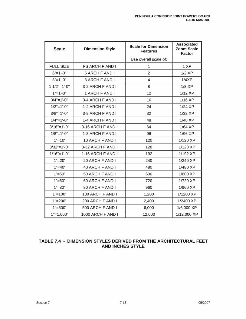
1”=1,000’ 1000 ARCH F AND I 12,000 1/12,000 XP TABLE 7.4 - DIMENSION STYLES DERIVED FROM THE ARCHITECTURAL FEET
AND INCHES STYLE

PENINSULA CORRIDOR JOINT POWERS BOARD CADD MANUAL
Section 7 7-16 05/2007
FIGURE 7.15 - EXAMPLES OF THE CIVIL DIMENSION STYLES

PENINSULA CORRIDOR JOINT POWERS BOARD CADD MANUAL
Section 7 7-17 05/2007
FIGURE 7.16 - EXAMPLES OF THE ARCHITECTURAL DIMENSION STYLES

PENINSULA CORRIDOR JOINT POWERS BOARD CADD MANUAL
Section 7 7-18 05/2007
7.4 NOTES
Where possible, notes applicable to a whole drawing shall be shown in the upper right-hand corner of the drawing. Additional columns may be used for notes with the information always reading starting from the left most column and proceeding to the right. Notes shall be of single spaced text, 1/8” (0.125”) high with a blank line between each note. The underlined word “NOTE:” or “NOTES:” in 0.140” high characters shall identify notes. See Figure 7.17.
FIGURE 7.17 - FORMAT FOR NOTES 7.5 LABELS (CALL OUTS)
Labels applicable to a particular part of a drawing shall be shown within the area of the detail, section or part to which they apply. MText shall not be attached to leaders. In the Leader Settings dialogue box, under the Annotation tab, the Annotation Type shall be set to “None”. Label text shall be 1/8” (0.125”) high.
7.6 MATCH LINES
Whenever drawing detail extends across multiple sheets or multiple viewports on the same sheet, match lines shall be provided where the detail begins and ends on each sheet or in each view. Match lines shall be drawn using the special PCJPB line type “Match” found in the line type file PCJPB.lin, PCJPB’s special line types file. See Appendix 6.

PENINSULA CORRIDOR JOINT POWERS BOARD CADD MANUAL
Section 7 7-19 05/2007
Generally, match lines shall be labeled “MATCH LINE SEE DWG X000.” For drawings that show alignments extending across multiple sheets or multiple viewports on the same sheet, the match lines shall be labeled to show the controlling alignment’s stationing as well. Thus: MATCH LINE MT1 200+56 SEE DWG C107, for example. Match lines cutting alignments shall cut the controlling alignment such that they are perpendicular to tangents and radial to curves and spirals of that alignment. Drawing detail shall be clipped at the match line. Should detail continue on the same sheet in a different viewport, the label shall read “SEE ABOVE RIGHT”, “SEE BELOW LEFT“, etc. as appropriate. Match line labels shall be shown parallel to the match line and on the side opposite of drawing detail. The drawing a match line label refers to shall be the abutting sheet on which the detail continues. Match line label text shall be 1/4” (0.25”) high. The line weight of match lines and their labels shall be 0.90mm. See Figure 7.18 below for examples.
FIGURE 7.18 - MATCH LINES

PENINSULA CORRIDOR JOINT POWERS BOARD CADD MANUAL
Section 7 7-20 05/2007
7.7 DETAILS, SECTIONS AND ELEVATIONS
7.7.1 General
Figures 7.19 and 7.20 below illustrate the PCJPB file/blocks used to call out and identify plans, details and elevations or cut and identify sections.
FIGURE 7.19 - BLOCKS FOR DETAIL, ELEVATION, PLAN, PROFILE AND
SECTION TITLES

PENINSULA CORRIDOR JOINT POWERS BOARD CADD MANUAL
Section 7 7-21 05/2007
FIGURE 7.20 - BLOCKS FOR CALLING OUT DETAILS, ELEVATIONS, CUTTING SECTIONS
7.7.2 Details
Details shall be identified with numerals. The drawing number(s) of the sheet(s) on which a particular detail is called out shall be shown on the left-hand side of its title. Should a detail be called out and shown in one and only one drawing, a horizontal bar shall replace the drawing number in both the callout and title. Where appropriate, enclose objects and/or areas to be shown in detail with a reference bubble. Reference bubbles shall be drawn using a dashed line of appropriate line weight and line type scale. See Figure 7.21 for illustrations of how to call out and identify details.
7.7.3 Sections
Sections shall be identified with letters. Sections shall be called out in alphabetical order from left to right and from top to bottom in a drawing. The drawing number(s) of the sheet(s) on which a particular section is called out shall be shown on the left-hand side of its title. Should a section be taken and shown in one and only one drawing, a horizontal bar shall replace the drawing number in both the callout and title. Figures 7.22 and 7.23 illustrate the treatment of sections. If a section is similar to one already shown, either on the same sheet or on another sheet, reference the existing section and state that the sections are similar. Another drawing showing the similar section would not then be required. The word "SIMILAR" shall be shown as "SIM" and shall be expanded to explain how the sections differ; such as "SIM, BUT OPP HAND" or SIM, EXCEPT AS NOTED." The word "SAME” shall not be used. See Figure 7.22.

PENINSULA CORRIDOR JOINT POWERS BOARD CADD MANUAL
Section 7 7-22 05/2007
FIGURE 7.21 - DETAIL EXAMPLES

PENINSULA CORRIDOR JOINT POWERS BOARD CADD MANUAL
Section 7 7-23 05/2007
FIGURE 7.22 - SECTION EXAMPLES

PENINSULA CORRIDOR JOINT POWERS BOARD CADD MANUAL
Section 7 7-24 05/2007
FIGURE 7.23 - SECTION EXAMPLES (CONTINUED)
7.7.4 Elevations
In many instances, elevations are treated in a fashion similar to details and sections. In such cases, elevations shall be identified with letters and shall be called out in alphabetical order from left to right and from top to bottom in a drawing. The drawing number(s) of the sheet(s) on which such an elevation is called out shall be shown on the left-hand side of its title. Should such an elevation be called out and shown in one and only one drawing, a horizontal bar shall replace the drawing number in both the callout and title. The discussion above for similar sections also applies to similar elevations. Figure 7.24 gives examples of the treatment of elevations.
7.7.5 Track Segment Cross Sections
Track segment cross sections cut at regular intervals for use in earthwork calculations and definition of limits of construction shall not be identified on plans.

PENINSULA CORRIDOR JOINT POWERS BOARD CADD MANUAL
Section 7 7-25 05/2007
FIGURE 7.24 - ELEVATION EXAMPLES

PENINSULA CORRIDOR JOINT POWERS BOARD CADD MANUAL
Section 7 7-26 05/2007
7.8 TITLES
Titles shall be provided under each part or sub-part of a drawing. The height and weight of text for main titles and subtitles shall be as specified in Figure 3.1. Main titles shall be underlined with a line of the same line weight as the title text. The underline shall span the length of the title including any scale notation. See Figures 7.19 through 7.24. Titles of cross sections cutting alignments shall include as a subtitle the station along the controlling alignment at which they are taken. For example, MT1 XXX+XX.
7.9 IDENTIFYING COMPONENTS
The components of equipment, fixtures, etc. shown in a drawing or detail shall be labeled as required using the same terminology as in the manufacturer’s technical specification. If abbreviations are used, they shall be the same as those shown on the abbreviations sheets.
E N D O F S E C T I O N 7

PENINSULA CORRIDOR JOINT POWERS BOARD CADD MANUAL
Section 8 8-i 05/2007
SECTION 8 DRAWING ORGANIZATION AND DESIGN GUIDELINES
CONTENTS
PART TITLE PAGE ______________________________________________________________________________________
8.1 GENERAL 8-1 8.2 PROJECT/MODULE DRAWING ORDER 8-1 8.3 CIVIL/TRACKWORK DRAWINGS 8-3 8.4 UTILITY DRAWINGS 8-10 8.5 ARCHITECTURAL DRAWINGS 8-13 8.6 LANDSCAPE DRAWINGS 8-15 8.7 STRUCTURAL DRAWINGS 8-16 8.8 MECHANICAL DRAWINGS 8-19 8.9 ELECTRICAL DRAWINGS 8-21 8.10 TRACTION POWER DRAWINGS 8-23 8.11 OVERHEAD CONTACT SYSTEM (OCS) DRAWINGS 8-25 8.12 COMMUNICATIONS DRAWINGS 8-27 8.13 FARE COLLECTION 8-28 8.14 SUPERVISORY CONTROL AND DATA ACQUISITION (SCADA) DRAWINGS 8-31 8.15 TRAIN CONTROL SYSTEM DRAWINGS (PENDING) 8-33 8.16 CORROSION CONTROL DRAWINGS (PENDING) 8-33 8.17 ROLLING STOCK DRAWINGS (PENDING) 8-33 FIGURES 8.1 TYPICAL ALIGNMENT PLAN SHEET 8-27 8.2 TYPICAL TRACK ALIGNMENT DATA TABLES SHEET 8-28 8.3 TYPICAL PLAN AND PROFILE SHEET 8-29 8.4 TYPICAL GENERAL PLAN AND SHEET INDEX DRAWING 8-30

PENINSULA CORRIDOR JOINT POWERS BOARD CADD MANUAL
Section 8 8-1 05/2007
SECTION 8 DRAWING ORGANIZATION AND
DESIGN GUIDELINES 8.1 GENERAL
When preparing designs for PCJPB, architects, engineers and other consultants shall adhere to the standards and best practices customary for their disciplines. Design and construction drawings submitted to PCJPB shall conform to the CADD specifications given in this Manual. When choosing architectural and engineering scales, keep in mind that drawings will typically be submitted, distributed and used on 11” x 17” sheets. This Section lists the types of drawings usually produced for PCJPB projects. Each project is unique, and thus the requirements for each will differ. Some may involve many disciplines, others only a few. For a larger project, work may be split up into modules, each module involving different localities and/or aspects of the project. Therefore, the submittal package(s) for each project or module will be unique; usually, not all disciplines and drawing types will be represented in each package. For all projects, however, submitted drawings shall be assembled in the same general order. The parts in this section give the order in which drawings are to be assembled for submittal to PCJPB. Part 8.2 outlines the overall assembly order of drawings for a project or module. Following parts discuss the content, scale and desired order for drawings within each discipline. These requirements shall apply to all design, construction and record drawing submittals. When a project involves multiple locations along Caltrain’s right-of-way, PCJPB recommends that the project drawings be assembled by location. That is that all drawings of the various disciplines pertaining to each locale be kept together and assembled in the order given in Part 8.2.
8.2 PROJECT/MODULE DRAWING ORDER
8.2.1 General
Drawings common to all disciplines, such as the Index of Drawings sheet(s), standard abbreviations sheet(s), etc., shall come first. Drawings for each discipline shall come next followed by any reference drawings.
Common Drawings:
• Cover/Title Sheet • Index of Drawings Sheet(s) • PCJPB General Notes (Provided by PCJPB) • PCJPB Standard Abbreviations (Provided by PCJPB) • PCJPB Standard Symbols (Provided by PCJPB) • General Plan/Sheet Index
PENINSULA CORRIDOR JOINT POWERS BOARD CADD MANUAL
Section 8 8-2 05/2007
• Track Charts Discipline Drawings:
• Civil/Track Work • Utility • Architectural • Landscape • Structural • Mechanical • Electrical • Traction • Overhead Contact System (OCS) • Communications • Fare Collection • Supervisory Control and Data Acquisition (SCADA) • Train Control • Corrosion Control • Rolling Stock
A typical example of civil drawings assembled for submittal is shown in Appendix 2.
8.2.2 Cover/Title Sheet
Each set of submitted project drawings shall have a Cover/Title sheet. The Cover/Title sheet shall show the Caltrain system map and logo, the project title and subtitles indicating the subject matter of the drawings included in the drawing set, volume information as necessary, the type of submittal and the submittal date. Cover/Title sheets shall be created by inserting the attributed file/block JPBCVR.dwg into blank drawing files and filling in its fields as required. See Figure 9.10 for an example.
8.2.3 Index of Drawings
The Index of Drawings shall show for each drawing in the project, in order of assembly, its page number, drawing number, revision level and title. PCJPB provides a prototype drawing file, INDX.dwg, which shall be used to create index of drawings sheets. See Figure 6.1.
8.2.4 PCJPB General Notes Sheet
This sheet contains notes applicable to the entire project. PCJPB will provide this sheet.
8.2.5 PCJPB Standard Abbreviations Sheets
PCJPB has developed a number of abbreviations sheets. They contain standard abbreviations to be used in all project drawings. PCJPB will provide these as required.

PENINSULA CORRIDOR JOINT POWERS BOARD CADD MANUAL
Section 8 8-3 05/2007
8.2.6 PCJPB Standard Symbols Sheets
PCJPB has also developed a number of symbols sheets. They contain standard symbols to be used in all project drawings. PCJPB will also provide these as required.
8.2.7 General Plan/Sheet Index
The General Plan/Sheet Index drawing shall be on a single sheet if possible. It shall provide an overview of the whole project within the limits of construction and show graphically the area covered by each plan and profile sheet in the plan set. Each indexed sheet shall be identified with its drawing number, which shall be placed within the sheet outline in the lower right-hand corner. This drawing shall also show alignments within the project limits. Any major structures to be built or modified as part of the project and their respective plan sheet numbers shall be shown as well. If space allows, survey control information may also be included on this sheet. The consultant civil engineer in charge shall stamp and sign this drawing. See Figure 8.4.
8.2.8 Master Track Chart
PCJPB produces and maintains a Master Track Chart for the whole Caltrain Corridor. It shows schematically the rails, rail type, track structure and the milepost locations of stations, grade crossings, utility crossings, bridges and other key structures. It also shows alignment information such as speed limits, curve data and grades. For each construction project, as part of the design effort, the design consultant shall modify sections of the Master Track Chart as required to show changes implementation of the design will make to the Caltrain corridor. PCJPB will provide the consultant with a copy of those sections of the Master Track Chart to be so modified. The consultant engineer in charge shall stamp and sign this drawing. Sometimes PCJPB will produce special construction and project development Track Charts which include information specific to particular projects.
8.3 CIVIL/TRACK WORK DRAWINGS
8.3.1 Drawing Order
Project drawing sets will not necessarily include all of the sheets listed below. The civil engineer(s) of record shall stamp and sign all drawings. When assembling drawings for submittal, the following general order shall be adhered to: • Civil/Track Work General Notes • Civil/Track Work Abbreviations and Symbols • Existing Conditions/Demolition Plans • Site Plans

PENINSULA CORRIDOR JOINT POWERS BOARD CADD MANUAL
Section 8 8-4 05/2007
• Survey Control Data • Mobilization, Construction and Maintenance Areas • Alignment Data and Tables • Plan and Profile • Typical Cross Sections • Typical Details • Grading and Paving Plan • Drainage Plan, Profiles and Details • Details and Sections • Construction Staging Plans • Traffic Maintenance Plans • Signing and Pavement Marking Plans • Signing and Pavement Marking Details • Traffic Signal Plans
8.3.2 Civil/Track Work General Notes
This drawing shall include notes pertaining to the civil/track engineering work and other applicable references specific to the project.
8.3.3 Civil/Track Work Abbreviations and Symbols
This drawing shall show additional civil/track work abbreviations and symbols specific to the project not shown on the PCJPB abbreviations and symbols sheets.
8.3.4 Existing Conditions/Site Demolition Plans
Prepared at a scale of 1”=40’, these drawings shall indicate the project site topography and conditions prior to the beginning of construction. The various buildings and other installations to be demolished, removed, transported off-site or otherwise disposed of shall be indicated on these drawings.
Aerial mapping done for the project may form the base detail for these drawings. Otherwise, PCJPB,s aerial topographic files shall be used. Caltrain track centerlines, right-of-way lines, milepost markers (at least every mile), street names and city, county and other jurisdictional lines shall be included on these drawings.
8.3.5 Site Plans
Site Plans shall show existing and proposed track, roadway alignments and other key facilities to be built as part of the project. Points of change in track geometry, point of switch locations, point of turnout intersection locations, switch designations and stationing of the control tracks or baselines shall be shown. Full stationing shall be indicated every 500 feet with intermediate ticks every 100 feet. Intermediate ticks shall be labeled with a numeral as appropriate (1 for 100 feet, 2 for 200 feet, etc). For additional information, see Subpart 8.3.9, Plan and Profile Sheet.
PENINSULA CORRIDOR JOINT POWERS BOARD CADD MANUAL
Section 8 8-5 05/2007
8.3.6 Survey Control Data
This drawing shall show the location and coordinates of primary benchmark and bearing control survey monuments within the project area. All new work shall have a tie to the survey control network delineated on this plan. If space allows, survey control information may be included on the General Plan/Sheet Index drawing.
8.3.7 Mobilization, Construction and Maintenance Areas
These drawings outline plans and schedules for setting up and subsequently dismantling any temporary facilities/operations necessary for the construction of a project.
• These drawings shall include an aerial photo or topographic
background. • They shall show general arrangements for the receiving, unloading and
storage of welded rail, along with details of the track work welding area.
• They shall show track work storage areas in relation to the project area, showing their general arrangement and identifying specific locations.
A. Mobilization
These drawings shall show the general arrangement relative to the overall project.
B. Construction
These plans shall show the location and general arrangement of construction site offices, staging and material storage areas, loading and unloading facilities, maintained access necessary for Caltrain operations and the public, etc.
C. Maintenance Access Areas
These plans shall show the overall arrangement of each Maintenance of Way Access area required for Caltrain’s maintenance crews with details of that area.
8.3.8 Alignment Plan and Data Tables
Alignment Plan
Alignment Plan sheets show the horizontal geometry of track centerlines. They shall show stationing along the centerlines and points of change in track geometry. Other information shown shall include track numbers--MT1, MT2, for example; point of switch locations; point of turnout intersection locations, the size or number of switches and their type (power, electric lock or hand thrown). A table shall be provided on each sheet showing the curve and line data for the centerline segments depicted on that sheet. Each curve on the plan shall be labeled with a

PENINSULA CORRIDOR JOINT POWERS BOARD CADD MANUAL
Section 8 8-6 05/2007
number to provide a cross-reference to its listing in the alignment data table. Alignment plans shall be drawn at a scale of 1”=100’. See Figure 8.1. For each project, PCJPB will provide designers with the coordinates of the initial project station for each alignment and the existing track elevation, bearing, etc. at that point. PCJPB will also provide existing track information at points where project alignments will tie back into existing track. Alignment Data Tables
Information shown in alignment data tables shall include alignment names (including the Land Development Desktop (LDD) database name), curve numbers, point of intersection stations, The lengths and bearings of tangents and the curve and spiral information listed below. See Figure 8.2. A. Circular Curve Data
Degree of Curve, Radius, Delta, Arc length (Arc Lc), Lc (Arc length based on 100’ chords), Tangent, Design Speed and coordinates for beginning and end of curve and radius point. See Figure 8.2.
B. Spiral Curve Data
Type of Spiral, TS, SC, CS, ST, Lc, Ls, R, D, O, Is, ∆c, Θs, Ts In, Ts, Out, Tc, X, Y, PI, SPI, P, K, LT, ST. See Figure 8.2.
In addition, the size of turnouts and locations (stationing, northings and eastings) for points of switches and points of intersection shall be included in the alignment data tables.
The alignment plan and data tables together with the plan and profile sheets (see below) shall provide all of the information needed to layout and construct track alignments.
8.3.9 Plan and Profile Sheets
Plans
Plans shall be prepared at a scale of 1”=40’. The plan shall include a topographic base covering the entire area of the project and the information listed below:
• Existing PCJPB right-of-way and easements. • Proposed track alignment(s) with stationing for all tracks, point of
switch locations, labeled turnouts, power, electric lock and hand thrown switches and the beginning and end points of curves.
• Any proposed easements or right-of-way acquisitions needed to construct the proposed track and/or facilities.

PENINSULA CORRIDOR JOINT POWERS BOARD CADD MANUAL
Section 8 8-7 05/2007
• Proposed improvements (roadways, curbs, structures, etc.) and, where appropriate, utilities, which may be shown on a separate utilities composite plan.
• Milepost locations along right-of-ways. • Street names. Profiles
Profiles shall be provided for all project track alignments. For each alignment, the top of rail of the lower of the two rails at any point along the alignment shall be used to generate the profile. Track profiles shall serve as the base elevation reference for any structures transverse to their respective alignments. All grade crossings, overpasses and/or underpasses, culverts and utilities crossing the alignments shall be depicted on their profiles. Profiles shall be shown on a grid produced using AutoCAD Land Development Desktop. The grid’s horizontal axis shall be graduated in increments of 50 feet. Existing and proposed track elevations for the alignment shall be shown at minimum every 100 feet along this axis. The vertical axis shall be graduated in 1 foot increments. Elevations along the vertical axis shall be shown at 2 foot intervals at both ends of the grid. The grid shall appear as if screened and be set behind the profile detail and accompanying text. The horizontal and vertical scales shall be indicated. Scale: Horizontal, 1”=40’; vertical, 1”=4’. Refer to Figure 8.3.
8.3.10 Typical Cross Sections
Typical cross sections shall be shown at appropriate locations along the track alignment. They shall include the trackway, roadway and other details with vertical and horizontal dimensions.
All track way drainage elements and system wide facilities including but not limited to track work, traction power, train control, communications and any other PCJPB facilities shall be included. Items to be installed or constructed in other contracts shall be identified.
Contract drawings for typical cross sections included in the bid package shall be used as a guide. The drawings shall be revised as required to conform to the detailed design.
8.3.11 Typical Details
Typical details shall be drawn to illustrate clearly specific elements of construction. They may include trackway, roadway, station, site and other miscellaneous civil details.
Details shall be drawn full-size in model space and then scaled in their respective layout viewports.

PENINSULA CORRIDOR JOINT POWERS BOARD CADD MANUAL
Section 8 8-8 05/2007
8.3.12 Grading and Paving Plans
Grading and paving plans shall depict proposed work along the trackway and at parking lots, access roads, city and county streets and highways adjacent to the rail line. These drawings shall be prepared for the construction of new facilities and/or for the restoration of existing facilities. Grading Plans shall show all vertical data required for construction.
Information Shown
A. Plans
The base for these plans shall be a topographic background showing existing conditions as discussed in Subpart 8.3.4. Existing contours and spot elevations shall be shown. Plans shall show structure outlines, street lines, walls, permanent and temporary easements, sidewalks, curbs, alleys, catch basins, manholes, fences, guard rails and other surface features to be constructed or affected by PCJPB construction. Existing and proposed elevations, curbs and other details for areas to be paved, repaved or restored shall be shown or referenced to other plans. The elevations of existing street surfaces at conforms shall be indicated. The top of curb and flow line elevations of proposed nonstandard curbs shall also be included.
B. Typical Grading Sections
Typical sections, cross sections or cross-section information and type of pavement shall be shown.
C. Drainage
Drainage plans shall include the layout of proposed and relocated above and below ground facilities, the size and material of pipes, types of channels and gutters, owner of facilities, etc. They shall provide cross-references to profiles and details on other drawings. The grades and flow lines of swales shall be shown. Proposed drainage facilities shall match and conform to existing facilities and conditions at project boundaries.
D. Spot Elevations
In general, spot elevations shall be provided as required to adequately define paved and graded surfaces. Unless profiles and typical sections adequately define finished pavement surfaces, spot elevations shall be provided as needed on centerlines, edges of pavement, gutter lines, faces of curbs, backs of sidewalks and along grade breaks. In areas to be graded, elevations shall be indicated along grade breaks, edges of restoration, centerlines of ditches and channels, within areas to be warped, in depressions and at high points.

PENINSULA CORRIDOR JOINT POWERS BOARD CADD MANUAL
Section 8 8-9 05/2007
E. Control Elevations
Control elevations shall be given at the tangent points of street corners or fillets, at points to be matched and as required for construction.
F. Existing Trees and Landscaping
Trees and landscaping to be saved shall be identified, unless they have already been so identified on the landscaping plans.
G. Contours
Contours defining finished surfaces shall be shown with solid lines. The contour interval shall be selected to portray relief details clearly. Tops, depressions, ditches, swales, slopes, grade breaks, curbs and gutters, etc. should be readily apparent from the contours. Each index contour shall be labeled at least once on each sheet.
H. Right-of-Way and Easement Lines
All right-of-way and easement lines shall be indicated on these drawings.
I. Separate Plans
If combined plans would be difficult to read because of the amount of detail on the drawings, separate grading and paving plans shall be prepared.
8.3.13 Drainage Plans, Profiles and Details
A. Drainage Plans
Drainage Plans shall include detailed layouts for all proposed and relocated drainage facilities. The drainage plans shall use PCJPB’s aerial mapping of the project site as a base. For some projects it may be possible to include the drainage plan on the Grading and Paving Plan. Information Shown
Drainage plans shall show manholes, catch basins, inlets, area drains, cleanouts, etc. Coordinates (northings and eastings) shall be given for the center of each structure. Alternatively, these structures may be located using stations and offsets from control lines/baselines established for the project. The horizontal alignments of major proposed storm pipes shall be designed using AutoCAD’s Land Development Desktop. Stationing for these alignments shall be shown on the plan.

PENINSULA CORRIDOR JOINT POWERS BOARD CADD MANUAL
Section 8 8-10 05/2007
B. Drainage Profiles
Drainage profiles shall be derived from the alignments of major storm sewer pipes. Profiles shall be generated using AutoCAD Land Development Desktop. Information Shown
Drainage profiles shall show pipe slope, diameter and material, structures, rim and invert elevations and the existing and proposed ground surfaces at pipe centerlines. Utilities crossing pipe alignments shall be shown in their correct position relative to the pipes and the clearances between them given.
C. Details
Typical and special details shall be shown. All details shall be drawn full-size in model space and scaled in their respective viewports as required. Typical details shall be developed using either Caltrans standard details, those of the local municipalities in which projects are located or PCJPB’s standard drawings.
8.3.14 Details and Sections Drawings
Profiles and miscellaneous sections and details supplementing information shown on grading, pavement and drainage plans shall be shown on separate details and sections drawings.
8.3.15 Construction Staging Plans
These plans shall show how a project is to be constructed. They indicate generally what needs to be done in a project and the sequence in which it is to be done, dividing the work into stages. They identify its various elements: Buildings, track, roads, etc., showing their location and when they are to be constructed. They also outline other tasks: Demolition, grading, landscaping, traffic control measures, public information measures, for example, and the sequence in which they are to occur. The scale of these drawings shall be as required.
8.3.16 Signing and Pavement Marking Plans
Signing and pavement marking plans shall be prepared in accordance with PCJPB criteria for PCJPB facilities and per Caltrans or local requirements for city and county facilities.
8.3.17 Signing and Pavement Marking Detail Drawings
Details shall show signs and pavement markings with detail and dimensioning sufficient for their procurement, fabrication and/or installation.

PENINSULA CORRIDOR JOINT POWERS BOARD CADD MANUAL
Section 8 8-11 05/2007
8.3.18 Traffic Signal Plans
Drawings for temporary and permanent traffic signals shall be prepared in conformance with the requirements of the governing municipality or PCJPB.
8.4 UTILITY DRAWINGS
8.4.1 Drawing Order
Project drawing sets will not necessarily include all of the sheets listed below. The civil engineer of record shall stamp all drawings. When assembling drawings for submittal, the following general order shall be adhered to: • Utility General Notes • Utility Abbreviations and Symbols • Composite Plans of Existing Utilities • Composite Plans of Utility Relocations • Utility Relocation Plans, Profiles and Details
8.4.2 Utility General Notes
This drawing contains notes and references pertaining to the utility work and other applicable references specific to the project.
8.4.3 Utility Abbreviations and Symbols
This sheet contains those utility abbreviations and symbols specific to a project not included on the PCJPB abbreviations and symbols sheets.
8.4.4 Composite Plans of Existing Utilities
Composite plans of existing utilities shall show the interrelationship of existing utilities and streets in the project area. Each Utility feature shall be designated as either existing or abandoned and its type, size and material indicated using abbreviations and symbols shown on the abbreviations and symbols sheets. Where the size of a utility line is greater than 18” in diameter, it shall be shown accurately to scale. Where the diameter is less than 18”, only the centerline of the utility line shall be shown.
Utilities to be Shown
The following types of utilities and their ancillary installations shall be plotted: • Overhead and underground power facilities • Water mains • Sanitary, storm and combined sewers • Overhead and underground telephone facilities including
fiber optic cables • Gas mains

PENINSULA CORRIDOR JOINT POWERS BOARD CADD MANUAL
Section 8 8-12 05/2007
• Overhead and underground cable television facilities • Pipeline company pressure mains • Overhead and underground telegraph facilities • Overhead and underground street light and traffic signal facilities • Railroad communication and signal cables • Emergency services communication cables • Other utilities as necessary • Invert at crossing
Utility Designations
Line designations shall be placed in the space between specific utility facilities. If congested, flag horizontally and perpendicular to right or left borders. When descriptive information is required, place it directly above the specific utility facility.
General
Line designation, curvature, stationing, stations, streets and match lines shall conform to the contract drawings.
8.4.5 Composite Plans for Utility Relocation
Utility relocation plans shall be prepared as authorized by PCJPB in coordination with and by agreement with utility owners and other contractors engaged in the utility work for a project. Composite plans for utility relocation shall show existing installations along with temporary and permanent relocations. These plans shall show storm drains and the utilities listed in Section 8.4.4. Those preparing these drawings shall ensure that no conflicts exist between proposed and existing utilities and that adequate space is available for the relocations and proposed installations. The scale of the composite plans for utility relocations shall match the scale of the composite plans of existing utilities.
Composite plans for utility relocation shall be prepared with the composite plans of existing utilities as a base. The base detail shall appear as if screened. These plans shall show all utility relocations with information sufficient to identify each utility line and its associated structures. Each structure along with any descriptive notes and information shall be shown only once on the composite plans.
8.4.6 Utility Relocation Plans, Profiles and Details
Utility relocation plans, profiles and details shall be developed for the construction of proposed utilities and/or the restoration/relocation of existing utilities. They also may show work utility owners will do within the project area. The scale of a project’s utility relocation plans shall match that of its composite plans of existing utilities.

PENINSULA CORRIDOR JOINT POWERS BOARD CADD MANUAL
Section 8 8-13 05/2007
Information to be Shown
In areas affected by construction, prepare utilities relocation plans, profiles and details for: • Storm sewers • Sanitary and combined sewers • Water mains • Gas mains • Fiber Optic Cable • Overhead and underground electrical facilities • Overhead and underground telephone facilities • Overhead and underground telegraph facilities • Cablevision facilities • Street lighting • Other utilities as necessary
Utility relocation plans shall show only that work pertaining to the utility or utilities indicated by the plan title. Where scales allow, it is preferred that relocation plans be prepared using the composite existing utility plans as a base. Utilities shall be drawn and labeled using the symbols and abbreviations shown on the general utility notes, abbreviations and symbols sheets. The type, size, material and owner of each utility shall be given. Label utilities as described in Section 8.4.4. Proposed utility lines shall be depicted with 0.70mm wide solid lines.
8.5 ARCHITECTURAL DRAWINGS
8.5.1 Drawing Order
Project drawing sets will not necessarily include all of the sheets listed below. The architect of record shall stamp all drawings. When assembling drawings for submittal, the following general order shall be adhered to: • Architectural General Notes • Architectural Abbreviations and Symbols • Site Plans • Floor Plans and Roof Plans • Reflected Ceiling Plans • Longitudinal and Transverse Sections • Exterior Elevations • Interior Elevations • Door, Hardware and Finish Schedules • Detail Plans, Sections and Elevations • Details
8.5.2 Architectural General Notes
This drawing contains notes pertaining to the architectural work, building codes, planning codes and other references specific to the project.

PENINSULA CORRIDOR JOINT POWERS BOARD CADD MANUAL
Section 8 8-14 05/2007
8.5.3 Architectural Abbreviations and Symbols
This drawing contains additional architectural abbreviations and symbols specific to the project not included on the PCJPB abbreviations and symbols sheets.
8.5.4 Site Plans
Site plans identify the location(s) and boundaries of project sites. The scale of a site plan shall be that engineering scale at which it most clearly depicts the site.
8.5.5 Floor Plans and Roof Plans
Floor plans shall show the configuration of all levels of proposed structures, identifying rooms and other spaces and their uses, the sizes and types of partitions, doors, windows, vertical circulation elements and any other elements of the layout. Roof plans shall show the layout of roof slopes, roof drainage systems, the locations of mechanical and electrical equipment and any other pertinent information.
8.5.6 Reflected Ceiling Plans
Reflected ceiling plans shall indicate locations and sizes of all ceiling fixtures, including the exposed ceiling grid and any other pertinent mechanical and electrical information.
8.5.7 Longitudinal and Transverse Sections
Longitudinal and transverse sections shall include all relevant vertical dimensions, material call outs and any other pertinent information.
8.5.8 Exterior Elevations
Exterior elevations shall show all exterior views of the facility, complete with dimensioning, material call outs, detail references and any other pertinent information.
8.5.9 Interior Elevations
Interior elevations shall show dimensions, material call outs and any other pertinent information, which cannot be shown clearly on the plans.
8.5.10 Door, Hardware and Finish Schedules
Door schedules shall give the door number together with its size, type and fire resistance rating, hardware specifications and references to head, jamb and sill details. Hardware schedules shall provide all the information necessary to procure and install hardware required by the design. Finish schedules shall identify for each room the material and finish for floor, walls and ceilings. Heights shall be included where required.

PENINSULA CORRIDOR JOINT POWERS BOARD CADD MANUAL
Section 8 8-15 05/2007
8.5.11 Detail Plans, Sections and Elevations
Detail plans, sections, including wall sections and elevations shall be shown at scales appropriate for the information presented. They shall include all relevant dimensions, material call outs and any other pertinent information.
8.5.12 Details
Details shall be provided in sufficient number to clearly depict the facility’s design and construction. They shall include all relevant dimensions, material call outs and any other pertinent information.
8.6 LANDSCAPE DRAWINGS
8.6.1 Drawing Order
Project drawing sets will not necessarily include all of the sheets listed below. The landscape architect of record shall stamp all drawings. When assembling drawings for submittal, the following general order shall be adhered to:
• Landscape General Notes • Landscape Abbreviations and Symbols • Layout Drawings • Planting Drawings • Irrigation Drawings • Miscellaneous Drawings
8.6.2 Landscape General Notes
This drawing contains notes that pertain to the landscape work and other applicable references specific to the project.
8.6.2 Landscape Abbreviations and Symbols
This drawing contains additional landscape abbreviations and symbols specific to the project not included on the PCJPB abbreviations and symbols sheets.
8.6.4 Layout Plans
Landscape layout plans shall be based upon civil drawings. These base plans shall show areas enlarged for clarity, special paving, horizontal expansion joints, benches, fences, bollards, other furniture and references to details.
8.6.5 Planting Plans
Planting plans shall indicate the areas to be planted. Plans shall show tree locations, shrub and ground cover spacing and lawn areas. Plants shall be called by their botanical name, and the size and quantity required of each type shall be shown, as well as any references to pertinent

PENINSULA CORRIDOR JOINT POWERS BOARD CADD MANUAL
Section 8 8-16 05/2007
details. Planting details shall provide installation directions and any applicable construction details. Notes shall be added to emphasize or clarify. Plans shall be of the same scale as civil drawings.
8.6.6 Irrigation Drawings
Irrigation plans shall indicate the areas to be irrigated. The different zones shall be shown along with their respective head types, controller locations, vacuum breakers and electrical connections. Also, the main water service connection, meters, backflow preventers and pressure-reducing valves, if required, shall be shown. Details shall provide installation directions and any applicable construction details. Notes shall be added when necessary to provide emphasis or clarification. Plans shall be of the same scale as civil drawings
8.6.7 Miscellaneous Drawings
Additional drawings, as required, shall show the extent and/or location of special features such as special walking finishes, bollards, benches, landscape lighting, bicycle racks, etc. These drawings shall include both plan and details sheets. Plans shall indicate the locations of these special features and provide references to details. The detail drawings shall provide construction and installation data. Plans shall be of the same scale as civil drawings.
8.7 STRUCTURAL DRAWINGS
8.7.1 Drawing Order
Project drawing sets will not necessarily include all of the sheets listed below. The structural engineer of record shall stamp all drawings. When assembling drawings for submittal, the following general order shall be adhered to: • Structural General Notes • Structural Abbreviations and Symbols • Location Plan and Logs of Borings • Construction Structures • Underpinning Shoring and Protection • Structural General Arrangement • Above Grade and Below Grade Structure Control Schedules • Structural Standard Drawings • Structural Plans • Structural Elevations Sections and Details • Structural Steel Framing Plans • Structural Steel Schedules and Details • Appurtenant Structures • Special Structures • Miscellaneous Iron and Steel

PENINSULA CORRIDOR JOINT POWERS BOARD CADD MANUAL
Section 8 8-17 05/2007
8.7.2 Structural General Notes
This drawing contains notes that pertain to the structural design work and references specific to the project.
8.7.3 Structural Abbreviations and Symbols
This drawing contains additional structural abbreviations and symbols specific to the project not included on the PCJPB abbreviations and symbols sheets.
8.7.4 Boreholes Location Plans and Logs of Borings
Boreholes shall be located and numbered according to the soils report prepared by the geotechnical consultant. The logs of borings shall be shown on separate drawings prepared by the geotechnical consultant.
Information Shown
Background information shall include streets, major buildings and the outline of track structures.
8.7.5 Construction Structures
These sheets shall be for the contractors’ use in designing and arranging temporary decking and support systems. Included shall be criteria for decking loads; sheeting and bracing loads; analysis and design information on lateral pressures caused by soil, water and surcharge; tiebacks; excavation and bracing procedures; allowable bearing values; observation installations and cofferdam arrangements.
8.7.6 Underpinning Shoring and Protection
The scale of these drawings shall be selected to suit the particular structure being underpinned. Drawings shall be complete in detail and shall clearly describe and indicate the method of underpinning to be used or the protection wall systems that might be required. Loads on existing columns and walls to be underpinned shall be shown.
8.7.7 Structural General Arrangement
• Plans
The outline of structure shall be superimposed on a simple outline of the street system.
• Profiles
The ground surface at the centerline of structure, the outline of structure and the track profile grade line shall be shown. If the profile grade lines of adjacent tracks are not the same, profiles of each track shall be shown. The elevation of top of low running rail shall be shown to the nearest one-hundredth of a foot at significant locations.

PENINSULA CORRIDOR JOINT POWERS BOARD CADD MANUAL
Section 8 8-18 05/2007
8.7.8 Above Grade and Below Grade Structure Control Schedules
These drawings shall show in tabular form the basic data for construction. The general consultant shall provide standard forms with headings and instruction for use.
8.7.9 Structural Standard Drawings
The structural Standard Drawings shall include standard structures and standard structural elements. Detailed information shall be presented in tabular form with required plans, sections, etc. and shall be provided by the general consultant.
8.7.10 Structural Plans
These drawings shall show the concrete outline and reinforcing details necessary to supplement those, which are shown on elevations, sections and details. They shall show clearance dimensions, tie-ins, joints, openings, rooms, etc. Drawings shall be arranged in sequence starting with lowest level, e.g., foundation plan or track level plan and progressing to roof level. In some instances structures might be represented by combination of plans, elevations, sections and details on the same drawing.
8.7.11 Structural Elevations Sections and Details
Views shall be referenced to the structural plans and shall show concrete and reinforcing adequate for the detailing of reinforcing steel.
8.7.12 Structural Steel Framing Plans
These drawings show the plan of columns, girders, beams, framing relationships and the designations of structural steel members.
8.7.13 Structural Steel Schedule and Details
Include schedules for columns, girders and beams in tabular form and details for joints and splices, end bearings and connections, stiffeners, anchor bolts, studs, base plates, bolting and welding, etc.
8.7.14 Appurtenant Structures
This grouping pertains to entrances, ventilation shafts and fan rooms, emergency exits, pump stations, etc. which are contiguous to the transit line or station structure. If on multiple sheets, plans, elevations, sections and details for each shall be assembled in the order outlined above.
8.7.15 Special Structures
This grouping includes overpasses, underpasses, nonstandard retaining walls, drainage structures, substations, utility structures and other miscellaneous structures not otherwise categorized.

PENINSULA CORRIDOR JOINT POWERS BOARD CADD MANUAL
Section 8 8-19 05/2007
8.7.16 Miscellaneous Iron and Steel
Include details for doors and frames, railings and handrail gratings and support members, ladders and stairs, anchor bolts and inserts, etc.
8.8 MECHANICAL DRAWINGS
8.8.1 Drawing Order
Project drawing sets will not necessarily include all of the sheets listed below. The mechanical engineer of record shall stamp all drawings. When assembling drawings for submittal, the following general order shall be adhered to: • Mechanical General Notes • Mechanical Abbreviations and Symbols • Site Plans • Heating, Ventilation and Air Conditioning (HVAC) Plans • HVAC Equipment Room Layout • HVAC Control Systems and Instrumentation • HVAC Flow Diagrams • HVAC Schedules • Plumbing and Drainage Plans • Plumbing and Drainage Equipment Room Layout • Plumbing and Drainage Riser Diagrams • Miscellaneous Piping Systems • Plumbing and Drainage Schedules • Fire Protection Plans • Fire Protection Equipment Room Layout
8.8.2 Mechanical General Notes
This drawing contains notes that pertain to the mechanical design work and other applicable references specific to the project.
8.8.3 Mechanical Abbreviations and Symbols
This drawing contains additional mechanical abbreviations and symbols specific to the project not included in the PCJPB abbreviations and symbols sheets.
8.8.4 Site Plans
A drawing of station and applicable portions of the parking lot or lots to show utility connection points, equipment room locations and areas to be irrigated with sprinklers.
8.8.5 HVAC Plans
General arrangement of heating, ventilation and air conditioning duct routing on screened backgrounds with non-applicable text deleted.

PENINSULA CORRIDOR JOINT POWERS BOARD CADD MANUAL
Section 8 8-20 05/2007
8.8.6 HVAC Equipment Room Layout
Plans shall show the general arrangement of air-handling equipment including space allocated for component replacement and equipment maintenance.
8.8.7 HVAC Control Systems and Instrumentation
A schematic diagram of control system, instrumentation devices, interconnecting piping and tubing and interfaces with other systems drawn to a size adequate to show the intent of the design.
8.8.8 HVAC Flow Diagrams
Schematic portrayal of air movement from air-handling equipment to conditioned space or area and its return or dispersal including make-up air and component arrangement drawn to an size adequate to show the intent of the design.
8.8.9 HVAC Schedules
Listing of HVAC equipment and devices showing pertinent information used for the design or minimum requirements, including fan capacity and filter efficiency.
8.8.10 Plumbing and Drainage Plans
General arrangement of plumbing and drainage piping shown on architectural backgrounds with non-applicable architectural text, such as room finish and door schedule references, removed.
8.8.11 Plumbing and Drainage Equipment Room Layouts
General arrangement of plumbing and drainage equipment including toilets, water heaters, circulating pumps, sump pumps and sewage ejectors.
8.8.12 Plumbing and Drainage Riser Diagrams
Schematic diagram of plumbing and drainage piping systems showing sequential arrangement of fixtures and devices drawn to an adequate size to show the intent of the design.
8.8.13 Miscellaneous Piping Systems
These drawings show the general arrangement of miscellaneous piping systems (e.g., the compressed air system) on screened architectural backgrounds with non-applicable architectural text deleted. Provide flow diagram of each system riser diagram for complex systems and equipment installation details.

PENINSULA CORRIDOR JOINT POWERS BOARD CADD MANUAL
Section 8 8-21 05/2007
8.8.14 Plumbing and Drainage Schedules
Listing of plumbing and drainage fixtures and devices showing pertinent information to be used for the design or minimum requirements, including supply sizes, trap sizes and vent sizes.
8.8.15 Fire Protection Plans
General arrangement of wet standpipe piping shown on screened architectural backgrounds with non-applicable architectural text deleted.
8.8.16 Fire Protection Equipment Room Layout
General arrangement of fire protection supply piping and devices, interfaces with other systems including backflow preventers, pumps and risers.
8.9 ELECTRICAL DRAWINGS
8.9.1 Drawing Order
Project drawing sets will not necessarily include all of the sheets listed below. The electrical engineer of record shall stamp all drawings. When assembling drawings for submittal, the following general order shall be adhered to:
• Electrical General Notes • Electrical Abbreviations and Symbols • Line Elements • Site Plans • Power Distribution One-Line Diagram • Exterior Lighting Plan • Interior Lighting Plan • Power and Grounding Plan • Communications Raceway Plan • Equipment Room Layouts • Communication Riser Diagrams • Control Diagrams • Details • Sections • Schedules
8.9.2 Electrical General Notes
This drawing contains notes that pertain to the electrical design work and other applicable references specific to the project.
8.9.3 Electrical Abbreviations and Symbols
This drawing contains additional electrical abbreviations and symbols specific to the project not included in the PCJPB abbreviations and symbols sheets.

PENINSULA CORRIDOR JOINT POWERS BOARD CADD MANUAL
Section 8 8-22 05/2007
8.9.4 Line Elements
The content of the drawings is also the same as required for stations. Many drawing types, however, may not be required and drawings may be incorporated onto the same drawing or sheet. Also, line elements shall be by individual element, compatible with the order of the structural drawings.
8.9.5 Site Plans
The site plan shall depict generally the electrical components to be installed or modified as part of the contract. The plan shall identify all electrical utility connection points, all major rooms and structures for electrical equipment and provide an overall layout showing the power and emergency power systems. The base shall be a screened site plan.
8.9.6 Power Distribution One Line Diagrams
Schematic representation of the electrical power distribution system from both normal and standby sources of supply down to the panel board level. Shows equipment normal voltage, current and short-circuit bracing ratings; metering, relaying, transformer connections and circuit breaker trip settings.
8.9.7 Exterior Lighting Plans
The lighting plan, including branch circuit wiring for the parking lot, shall locate and designate all light poles and fixtures and illuminated signage, which shall meet the site program and design criteria.
8.9.8 Interior Lighting Plans
The lighting plans for interiors shall locate and identify all fixtures and illuminated graphics. Symbols, fixture designation and branch circuit wiring shall meet the design criteria and shall conform to the Standard Drawings. The interior lighting plan may be combined with the auxiliary power plan if clarity is maintained.
8.9.9 Power and Grounding Plans
Plan shall locate all equipment served by multiple circuit breakers and show feeder routing. Grounding routing between equipment rooms shall be shown and grounding detail shall be shown on equipment room layouts. Equipment designations and symbols shall meet the design criteria and shall conform to the Standard Drawings.
8.9.10 Communications Raceway Plans
Plan shall show layout of public telephone, fire alarm systems, raceway systems for closed-circuit television (CCTV) and CALTRAIN telephone systems (PABX, emergency, courtesy and maintenance telephones). Symbols shall meet design criteria and shall conform to the Standard Drawings.

PENINSULA CORRIDOR JOINT POWERS BOARD CADD MANUAL
Section 8 8-23 05/2007
8.9.11 Equipment Room Layouts
General arrangement of power generation, distribution, public telephone, control and fire alarm equipment in switchboard, generator, main electrical equipment and auxiliary electrical equipment rooms. Ground test stations and grounding shall also be shown on these layouts.
Equipment room layout drawings include wall elevation of auxiliary electric rooms and train control rooms where needed to position equipment or components within a limited area.
8.9.12 Communication Riser Diagrams
Riser diagrams shall show general equipment interconnection and system interface with other subsystems covering supervisory control, alarms, annunciation, public address, closed-circuit TV, telephone system and system wide cable network components and devices.
8.9.13 Control Diagrams
Control drawings shall include site specific control circuit diagrams developed from the Standard Drawings. The terminal numbering scheme shown on Standard Drawings shall be followed to develop project drawings.
8.9.14 Details
Detail drawings showing methods of installation, equipment configuration and fixture mounting. Drawing scale shall be appropriate for information to be shown.
8.9.15 Sections
Section views and details, at an enlarged scale, shall be prepared by the contractor to clearly illustrate conduit arrangement and details necessary for installation.
8.9.16 Schedules
Required schedules shall include those for conduits, cables, motor control center and lighting. Distribution panel boards schedules shall be as illustrated on Standard Drawings.
A. Conduit Schedules
A schedule which separates the auxiliary electrical, communications, train control, fare collection and traction power raceway requirements shall be included with drawings. Format shall follow the Standard Drawings.
B. Panel Board Schedules
A panel board schedule shall be prepared for all main and subpanel boards. Format shall follow the Standard Drawings.

PENINSULA CORRIDOR JOINT POWERS BOARD CADD MANUAL
Section 8 8-24 05/2007
8.10 TRACTION POWER FACILITY DRAWINGS
8.10.1 Drawing Numbers, CADD File Naming System and Drawing Structure
Drawing numbers shall be allocated by drawing type/category and include “spare/unused” numbers for future use. The designer shall finalize drawing numbers with PCJPB prior to commencement of design development activities.
8.10.2 Drawing Scale
Design drawings of similar type shall use uniform scales. The designer shall finalize drawing scales with PCJPB prior to commencement of design development activities. Examples of scales for consideration by drawing type/category include: • Introductory Drawings, Single Line Diagrams, Control Schematics,
Schedules – no scale • Site Plans (e.g. Existing Conditions/Demolition, Grading and Paving,
Drainage, Site Access Roadways, Existing Utilities and Utility Relocation Composite, etc.) – 1”=40’-0”.
• Equipment Plans (e.g. Arrangement, Grounding, Duct Bank/Trench/Cable Vault, Structural Steel, etc.) - 1”=20’-0”
8.10.3 Drawing Order
Project drawing sets will not necessarily include all of the sheets listed below. The electrical engineer in charge shall stamp all drawings. The general order of arrangement shall be adhered to. Omit those drawings not applicable:
• Introductory Drawings (e.g. General Notes, Abbreviations and
Symbols, Device List, etc.) • Single-Line Diagrams • Meter and Relay Single Line Diagrams • Auxiliary/House Power Single Line Diagrams • Circuit Breaker Control Schematics • Civil Design Drawings per Section 8.3 above • Traction Power Facility Site Access Plans • Utility Design Drawings per Section 8.4 above • Landscaping Design Drawings per Section 8.6 above • Traction Power Facility Equipment Arrangement Plans and Elevations • Structural Steel Design Drawings per Section 8.7 above • Equipment/Structural Steel Foundation Plans and Sections • Traction Power Facility Grounding Grid Plans • Conduit and Cable Schedules • Manhole Schedules • Power Panel Schedules • Typical Installation Details

PENINSULA CORRIDOR JOINT POWERS BOARD CADD MANUAL
Section 8 8-25 05/2007
8.10.4 Introductory Drawings
General Notes: This drawing contains notes that pertain to traction power facility design and other applicable references specific to the project. Abbreviations and symbols: This drawing contains additional traction power abbreviations and symbols specific to the project not included in the PCJPB abbreviations and symbols sheets. Device Lists: All alphabetic, numeric and alphanumeric designators used to identify traction power equipment and devices used in the design drawings shall be shown on the device list.
8.10.5 Single-Line Diagrams
The power system for each substation, paralleling station and switching station shown on the master single-line diagram shall be depicted on separate single-line diagrams.
8.10.6 Meter and Relay Single Line Diagrams
The metering and relay requirements for each substation, paralleling station and switching station shown on the master single-line diagram shall be depicted on separate meter and relay single-line diagrams.
8.10.7 Auxiliary/House Power Single Line Diagrams
The auxiliary/house low voltage power requirements for each substation, paralleling station and switching station shown on the master single-line diagram shall be depicted on separate 480/277 V and 120 V single-line diagrams.
8.10.8 Control Schematics
Control schematic drawings shall be prepared for all equipment and devices installed in traction power facilities, including traction power substations, paralleling stations and switching stations. Symbols, device numbers, location abbreviations and terminology shall match those provided by PCJPB, and if none is provided, then the standard Institute of Electrical and Electronics Engineers (IEEE) convention shall be employed. Devices and all of their functional components, such as termination points, contacts, coils and switch positions, shall be properly and uniquely labeled. Control schematic drawings shall show all relaying, control, communications and indication functions of the involved equipment and devices. Overall arrangement of the drawings shall be such that they remain legible and convenient for use when reduced to one-half size.
8.10.9 Traction Power Facility Site Access Plans
Drawings shall be prepared depicting required site access roads and hard standing for parking at each traction power facility location. Roadway connections to existing city, county and/or state facilities shall be shown,

PENINSULA CORRIDOR JOINT POWERS BOARD CADD MANUAL
Section 8 8-26 05/2007
including grading and drainage. This information shall be placed over screened backgrounds.
8.10.10 Traction Power Facility Equipment Arrangement Plans and Elevations
Layout drawing shall be prepared for substations, paralleling stations and switching stations. This information shall be placed over screened backgrounds.
8.10.11 Equipment/Structural Steel Foundation Plans and Sections
Plans shall be prepared for all equipment, structural steel and perimeter barrier foundations at each traction power facility location.
8.10.12 Traction Power Facility Grounding Grid Plans
Plans shall be prepared for the grounding grid at each traction power facility. Connections to the grounding grid for all structural elements, such as fencing, termination structures and buildings and power equipment at each power facility location shall be detailed.
8.10.13 Schedules
Required schedules shall include, but not be limited to, the following: manholes, conduits, cables and power panels. Power panel schedules shall be as illustrated on Standard Drawings.
Manhole Schedules
A manhole schedule shall be prepared.
Conduit and Cable Schedules
Conduits and cables shown on traction power facility layout drawings shall be assigned unique numbers. Conduit and cable schedules shall be prepared, listing assigned numbers along with the type, size and routing of conduits and cables. Conduit contents shall be clearly identified. Conduit and cable lengths shall be determined and shown, either in the conduit and cable schedules or on the drawings. Format shall follow the Standard Drawings. Panel Board Schedules
A panel board schedule shall be prepared for all main and subpanel boards. Format shall follow the Standard Drawings.
8.10.14 Installation Details
Detail drawings shall be included showing methods of installation, equipment configuration and fixture mounting. Drawing scale shall be appropriate for information to be shown.

PENINSULA CORRIDOR JOINT POWERS BOARD CADD MANUAL
Section 8 8-27 05/2007
8.11 OVERHEAD CONTACT SYSTEM (OCS) DRAWINGS
8.11.1 Drawing Order
Project drawing sets will not necessarily include all of the sheets listed below. The electrical engineer in charge shall stamp all drawings. The general order of arrangement shall be adhered to. Omit those drawings not applicable:
• OCS General Notes • OCS Abbreviations and Symbols • OCS Sectionalizing Diagrams • OCS Tension Length Diagrams • OCS Technical Sheets • OCS General Arrangement Drawings • OCS Assemblies • OCS Wiring Layouts • OCS Conductor, Cable and Conduit Schedules
8.11.2 OCS General Notes
This drawing contains notes that pertain to OCS design and other applicable references specific to the project.
8.11.3 OCS Abbreviations and Symbols
This drawing contains additional OCS abbreviations and symbols specific to the project not included in the PCJPB abbreviations and symbols sheets.
8.11.4 OCS Sectionalizing Diagrams
The electrical sectionalizing of the traction power distribution system shall be depicted in Sectionalizing Diagrams and shown on the Track Charts in a separate single-line representation.
8.11.5 OCS Tension Length Diagrams
The Track Charts shall be used as the base document for depicting the master OCS tension length diagrams, which shall identify the location of all overlaps, balance weight and fixed termination anchors and mid-point anchors. These diagrams shall facilitate construction planning.
8.11.6 OCS Technical Sheets
The OCS technical sheets shall provide details of the required conductors, wires and cables. Design and installation data shall be shown, including structure spacing, wire tensions, conductor loading, hanger lengths and pantograph clearance envelopes.

PENINSULA CORRIDOR JOINT POWERS BOARD CADD MANUAL
Section 8 8-28 05/2007
8.11.7 OCS General Arrangement Drawings
The OCS general arrangement drawings shall provide information on typical tension lengths, insulated and uninsulated overlaps, phase break, side pole and headspan power feeding arrangements, section insulators and disconnect switches, bridge and tunnel arrangements, crossovers and turn-outs and typical sections throughout the right-of-way.
8.11.8 OCS Assembly Drawings
The OCS assembly drawings shall depict typical details of foundations, poles and structures and wiring assemblies from cantilevers and headspans through hangers and jumpers. Material allocation references shall be shown against each assembly.
8.11.9 OCS Wiring Layouts
The OCS wiring layouts shall be overlaid on top of the track alignment drawings for the entire route. The track alignment centerline shall be shown. For simple open route sections, the OCS conductor staggers shall be stated numerically. For complex track configurations, the OCS wiring shall be depicted both graphically and numerically. OCS support structures, comprising steel poles and cantilever bracket arms for simple single-track applications and multi-track support structures, such as steel portal frames or headspans in complex areas, shall be shown. Site specific materials allocation by assembly reference shall be given, together with relevant installation dimensions and data, sufficient to define the required catenary configuration.
8.11.10 OCS Conductor, Cable and Conduit Schedules
OCS conductors, cables and conduits, as shown in the OCS wiring layout drawings, shall be assigned unique numbers. Conductor, cable and conduit schedules shall be prepared, listing the assigned numbers, along with the type, size and routing of conduits and cables. Conduit contents shall be clearly identified. Conductor, cable and conduit lengths shall be determined and shown either in the conductor, cable and conduit schedules or on the drawings.
8.12 COMMUNICATIONS DRAWINGS
8.12.1 Drawing Order
Project drawing sets will not necessarily include all of the sheets listed below. The electrical engineer of record shall stamp all drawings. When assembling drawings for submittal, the following general order shall be adhered to:
• Communications General Notes • Communications Abbreviations and Symbols • Subsystem Block Diagrams • Functional Block Diagrams • Riser Diagrams

PENINSULA CORRIDOR JOINT POWERS BOARD CADD MANUAL
Section 8 8-29 05/2007
• Equipment Arrangement Plans • Facility Layout Plans • Installation Details • Conduit and Cable Schedules
8.12.2 Communications General Notes
This drawing contains notes that pertain to the communications design work and other applicable references specific to the project.
8.12.3 Communications Abbreviations and Symbols
This drawing contains additional communications abbreviations and symbols specific to the project not included in the PCJPB abbreviations and symbols sheets.
8.12.4 Subsystem Block Diagrams
Block diagrams shall be prepared for each of the communications subsystems showing the system configuration and identifying the major components at each location. Interconnection detail and relationship to the transmission circuits need not be shown.
8.12.5 Functional Block Diagrams
Functional block diagrams shall show the relationship of the functions for a subsystem installation within a facility. Functions shall be shown as blocks and the information flow shall be depicted. Location of the blocks by cabinets may be shown.
Typical locations of repeater and splice boxes, base radio enclosures and antenna installed along the wayside shall be shown.
8.12.6 Riser Diagrams
Riser diagrams shall show the general interface with other subsystems covering supervisory control, alarms, annunciation, public address, visual messaging, closed-circuit TV, the telephone system and system wide cable network components and devices.
8.12.7 Equipment Arrangement Plans
Equipment arrangement drawings shall show the physical location of communications and related equipment. Communications cabinets and racks, train control cabinets, cable trays, termination and interface cabinets, batteries and dedicated power distribution equipment in train control and communications rooms shall be shown.
8.12.8 Facility Layout Plans
Layouts shall include grounding, raceways, power systems and lighting for each specific site. The information shall be placed over screened backgrounds.

PENINSULA CORRIDOR JOINT POWERS BOARD CADD MANUAL
Section 8 8-30 05/2007
8.12.9 Installation Details
These drawings shall show typical mounting details for installing the communications equipment depicted. Mounting heights, method of fastening, dimensions and other pertinent information shall be included. A bill of materials shall be included.
8.12.10 Conduit and Cable Schedules
These schedules shall tabulate the communication systems cables routed between facilities. The routing of each cable via conduit and wireway shall be identified.
8.13 FARE COLLECTION
8.13.1 Drawing Order
Project drawing sets will not necessarily include all of the sheets listed below. The electrical engineer of record shall stamp all drawings. When assembling drawings for submittal, the following general order shall be adhered to:
• Fare Collection General Notes • Fare Collection Abbreviations and Symbols • Subsystem Block Diagrams • Equipment Arrangement Plans • Layout Plans • Installation Details • Conduit and Cable Schedules
8.13.2 Fare Collection General Notes
This drawing contains notes that pertain to the fare collection design work and other applicable references specific to the project.
8.13.3 Fare Collection Abbreviations and Symbols
This drawing contains additional fare collection abbreviations and symbols specific to the project not included in the PCJPB abbreviations and symbols sheets.
8.13.4 Subsystem Block Diagrams
Block diagrams for the automatic fare collection (AFC) and data acquisition systems (DAS) subsystems shall show the subsystems configuration. Major components shall be identified.
8.13.5 Equipment Arrangement Plans
These layout plans shall show the arrangement of the AFC equipment in plan and elevation views complete with the locations of all devices and display legends.

PENINSULA CORRIDOR JOINT POWERS BOARD CADD MANUAL
Section 8 8-31 05/2007
8.13.6 Layout Plans
Layout plans of areas with AFC equipment shall show under floor duct systems including power cabling, pneumatic lines and control wiring. Conduits with power and cabling for other machines shall be included. The background plans shall be screened.
8.13.7 Installation Details
These details shall show the base of all AFC equipment complete with anchor bolt and conduit stub-up locations. Details on anchor bolt, conduit stub-up and pneumatic line locations shall be shown in specific installation detail drawings.
8.13.8 Conduit and Cable Schedules
These schedules tabulate the AFC and DAS cables routed between equipment. The routing of each cable via conduit and wireway shall be identified.
8.14 SUPERVISORY CONTROL AND DATA ACQUISITION (SCADA)
DRAWINGS
8.14.1 Drawing Numbers, CADD File Naming System and Drawing Structure
Drawing numbers shall be allocated by drawing type/category and include “spare/unused” numbers for future use. The designer shall finalize drawing numbers with PCJPB prior to commencement of design development activities.
8.14.2 Drawing Scale
Design drawings of similar type shall use uniform scales. The designer shall finalize drawing scales with PCJPB prior to commencement of design development activities. Examples of scales for consideration by drawing type/category include: • Introductory Drawings, Block Diagrams, Schedules – no scale • Equipment Plans (e.g. Arrangement) - 1”=20’-0”
8.14.3 Drawing Order
Project drawing sets will not necessarily include all of the sheets listed below. The electrical engineer in charge shall stamp all drawings. The general order of arrangement shall be adhered to. Omit those drawings not applicable:
• Introductory Drawings (e.g. General Notes, Abbreviations and
Symbols, Device List, etc.) • Block Diagrams • Communication System Interface Diagram • SCADA Equipment Arrangement Plans and Elevations • SCADA Interface Cabinet Wiring Diagrams

PENINSULA CORRIDOR JOINT POWERS BOARD CADD MANUAL
Section 8 8-32 05/2007
• Local User Interface • Conduit and Cable Schedules • Typical Installation Details
8.14.4 Introductory Drawings
General Notes: This drawing contains notes that pertain to SCADA facility design and other applicable references specific to the project. Abbreviations and Symbols: This drawing contains additional SCADA abbreviations and symbols specific to the project not included in the PCJPB abbreviations and symbols sheets.
Device Lists: All alphabetic, numeric and alphanumeric designators used to identify SCADA equipment and devices used in the design drawings shall be shown on the device list.
8.14.5 Block Diagrams
System Architectural Block Diagrams
Block diagrams shall be prepared showing the system architecture and identifying the major components at each location. Interconnection detail and relationship to the transmission circuits need not be shown.
Functional Block Diagrams
Functional block diagrams shall show the relationship of the functions for a system installation within a facility. Functions shall be shown as blocks and the information flow shall be depicted. Location of the blocks by cabinets may be shown.
8.14.6 Interface Diagrams
Riser diagram shall show general interface with other subsystems including, but not limited to, the following: communications and fire detection subsystems.
8.14.7 Equipment Arrangement Plans and Elevations
Layout drawing shall be prepared for substations, paralleling stations and switching stations. This information shall be placed over screened backgrounds.
8.14.8 Interface Cabinet Wiring Diagrams
Drawings depicting the wiring termination points and monitoring and control functions for all applicable equipment shall be prepared for each substation, paralleling station, switching stations, wayside equipment enclosure, etc.

PENINSULA CORRIDOR JOINT POWERS BOARD CADD MANUAL
Section 8 8-33 05/2007
8.14.9 Local User Interface
Drawings depicting the user interface and associated control and monitoring displays shall be prepared for each substation, paralleling station and switching station
8.14.10 Schedules
Required schedules shall include, but not be limited to, the following: manholes, conduits and cables.
Manhole Schedules
A manhole schedule shall be prepared.
Conduit and Cable Schedules
Conduits and cables shown on traction power facility layout drawings shall be assigned unique numbers. Conduit and cable schedules shall be prepared, listing assigned numbers along with the type, size and routing of conduits and cables. Conduit contents shall be clearly identified. Conduit and cable lengths shall be determined and shown, either in the conduit and cable schedules or on the drawings. Format shall follow the Standard Drawings.
8.14.11 Installation Details
Detail drawings showing methods of installation, equipment configuration and fixture mounting. Drawing scale shall be appropriate for information to be shown.
8.15 TRAIN CONTROL SYSTEM DRAWINGS
To be included in a later revision of the CADD Manual. 8.16 CORROSION CONTROL DRAWINGS
To be included in a later revision of the CADD Manual. 8.17 ROLLING STOCK DRAWINGS
To be included in a later revision of the CADD Manual.
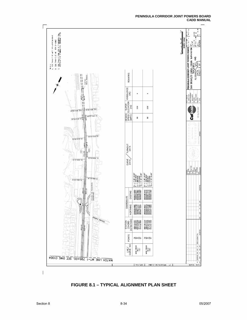
PENINSULA CORRIDOR JOINT POWERS BOARD CADD MANUAL
Section 8 8-34 05/2007
FIGURE 8.1 – TYPICAL ALIGNMENT PLAN SHEET

PENINSULA CORRIDOR JOINT POWERS BOARD CADD MANUAL
Section 8 8-35 05/2007
FIGURE 8.2 – TYPICAL TRACK ALIGNMENT DATA TABLE SHEET

PENINSULA CORRIDOR JOINT POWERS BOARD CADD MANUAL
Section 8 8-36 05/2007
FIGURE 8.3 – TYPICAL PLAN AND PROFILE SHEET

PENINSULA CORRIDOR JOINT POWERS BOARD CADD MANUAL
Section 8 8-37 05/2007
FIGURE 8.4 – TYPICAL GENERAL PLAN AND SHEET INDEX DRAWING
E N D O F S E C T I O N 8

PENINSULA CORRIDOR JOINT POWERS BOARD CADD MANUAL
Section 9 9-i 05/2007
SECTION 9 DRAWING DEVELOPMENT AND REVISION
CONTENTS
PART TITLE PAGE ______________________________________________________________________ 9.1 GENERAL 9-1 9.2 DRAWING DEVELOPMENT MILESTONES 9-1 9.3 REVISION PROCEDURES 9-2 9.4 RECORD DRAWINGS 9-4
FIGURES
9.1 REVISION CLOUDS AND TRIANGLES 9-4
9.2 RECORD DRAWING NOTE 9-4
9.3 DESIGN PHASE DRAWING REVISION BLOCKS AND FILE NAME 9-5
9.4 ISSUED FOR BID DRAWING REVISION BLOCK AND FILE NAME 9-5
9.5 ISSUED FOR BID PHASE ADDENDA REVISION BLOCKS AND FILE NAME 9-5
9.6 CONFORMED DRAWING REVISION BLOCK AND FILE NAME 9-6
9.7 CONSTRUCTION DRAWING REVISION BLOCKS AND FILE NAME 9-6
9.8 RECORD DRAWING REVISION BLOCK AND FILE NAME 9-6
9.9 RECORD DRAWING 9-7
9.10 RECORD DRAWING COVER/TITLE SHEET 9-8

PENINSULA CORRIDOR JOINT POWERS BOARD CADD MANUAL
Section 9 9-1 05/2007
SECTION 9 DRAWING DEVELOPMENT AND REVISION
9.1 GENERAL
This Section outlines the process by which drawings for PCJPB projects are developed. PCJPB furnished AutoCAD reference files, files/blocks, contract drawings and standard drawings are not developed as part of projects and are not subject to this process. Only PCJPB revises these files. Designers create, develop and revise project drawings during several project phases as discussed below. During these phases, project drawings are periodically submitted along with their associated CADD files for review. PCJPB’s engineering staff reviews the submitted drawings for design, and the CADD Department reviews (audits) the CADD files for conformance to the CADD criteria set out in this Manual.
9.2 DRAWING DEVELOPMENT MILESTONES
9.2.1 Design Phase
Work during this phase results in final design drawings which show the goals of a project, what it is that is to be done. As a design is developed, it usually goes through several revisions. When a revision is completed, drawings are submitted to PCJPB for review and comment. These submittals are known as interim or percentage submittals (30%, 65%, etc).
9.2.2 Issued For Bid (IFB) Phase
During the Issued for Bid phase, approved design drawings go out to contractors so that they can bid on the construction work. During the bid period, additional design work is sometimes needed. The resulting revisions during this phase are called Addenda.
9.2.3 Conformed Phase (Issued For Construction)
During this phase PCJPB awards contracts to successful bidders. Contract documents packages include drawings approved for use in construction. These drawings incorporate the revisions (addenda) made during the IFB phase.
9.2.4 Construction Phase (Project Records)
After construction begins, further clarifications and/or changes to a design may be necessary. In these cases, designers provide clarifications or make revisions and issue field bulletins and change orders. The contractor maintains one full-size set of Conformed Drawings as the Daily Project Record Set. As field bulletins and change orders are issued, the

PENINSULA CORRIDOR JOINT POWERS BOARD CADD MANUAL
Section 9 9-2 05/2007
contractor records in red ink all the changes specified in them on this set of drawings.
9.2.5 Record Drawings Phase (As-Builts)
When construction of a project is finished, the contractor prepares a Final Project Record (As-Built) set for the project. This is a set of construction drawings marked up in the field to show where and how the project as constructed deviates from the project as originally designed. At minimum, the contractor transfers all changes noted on the Daily Project Record Set (whether from field bulletins, change orders or some other source) on to a new, clean, reproducible set of the project’s Conformed Drawings. These As-Built drawings are then used to create a final revision of the conformed set of project CADD files. These revised files and the drawings plotted from them form the project’s Record Drawings, a permanent record of the project.
9.3 REVISION PROCEDURES
9.3.1 General
Revision levels shall be controlled and assigned by the discipline professional “in responsible charge”. Generally, a new revision level is assigned to a drawing or set of drawings whenever warranted. This Part outlines specific revision procedures for each project phase.
Revisions to drawings shall be highlighted with revision clouds drawn using a scalloped line 0.50 mm in width. Revision clouds shall enclose revised areas of drawings and be labeled with a revision triangle (AutoCAD file/block JPBTRI.dwg), which touches the cloud and indicates the level of the revision. When drawings reach the next revision level, all revision clouds associated with the previous level shall be removed and new revision clouds and triangles highlighting the newly revised areas added. Triangles labeling the revisions of previous levels shall remain. When a project moves into a new phase (from the IFB phase into the Conformed phase, for example) all evidence of revisions from the previous phase shall be removed from the drawings, and the process shall begin again. See Figure 9.1.
During drawing development, in order to track revisions, CADD file names shall be updated and revision information inserted into drawing borders as discussed below. See Parts 3.3 and 4.16 for more information. Drawing indexes shall be maintained throughout all project phases and shall be reissued as necessary so that they always reflect the current revision levels of project drawings.
9.3.2 Design Drawings
Letters of the alphabet shall be used throughout the design phase to denote a drawing’s revision level. Revision blocks (JPBREV.dwg) shall be inserted into drawing borders as necessary to indicate the current revision level of each drawing. The value in the drawing border revision

PENINSULA CORRIDOR JOINT POWERS BOARD CADD MANUAL
Section 9 9-3 05/2007
level boxes (Part 4.9) shall be kept current as well. Letters denoting revision levels shall also be appended with a dash to the file names of revised CADD files. See Figure 9.3.
9.3.3 Issued For Bid Drawings
After a design is finalized and approved, and before the drawings are issued for bid, all indicators of revisions from the design phase shall be removed. New revision blocks (JPBREV.dwg) shall be inserted into the drawing borders. The revision level in the revision blocks shall be set to “0” and the revision description to “ISSUED FOR BID.” The value in drawing border revision level boxes shall be set to “0”. All CADD file names shall be updated as well by eliminating any design phase revision designators and appending “-B0” (-B zero) to the ends of the file names. See Figure 9.4.
Should revisions be necessary after drawings are issued for bid, revision clouds and triangles highlighting the revisions shall be added to the drawings. Additional revision blocks (JPBRVT.dwg) shall be inserted into drawing borders above the “ISSUED FOR BID” designation as necessary. Drawing border revision level box values and CADD file names shall be updated as well. In the names of revised issued for bid CADD files, for the first revision, the “0” in “-B0” shall increment to “1”. For the second, the “1” shall increment to “2” and so on. See Figure 9.5. Issued for bid drawings shall be signed and stamped by the responsible registered professional engineer or licensed architect in accordance with Sections 4 and 10. See Figure 4.3.
9.3.4 Conformed Drawings
When drawings are conformed, all indications of revisions from the IFB phase shall be removed. New revision blocks (JPBREV.dwg) shall be inserted into drawing borders with the revision level set to “0” and the description reading “CONFORMED.” The value in drawing border revision level boxes shall revert to “0.” All CADD file names shall be updated as well by replacing any revision level designators from the IFB phase with “-0” (-zero). See Figure 9.6.
As with issued for bid drawings, conformed drawings shall also be signed and stamped by the responsible registered professional engineer or licensed architect.
9.3.5 Construction Drawings
Revision blocks, clouds and triangles shall be used and CADD file names updated as in earlier phases to indicate changes to construction drawings. Numerals shall indicate the revision levels of construction drawings. For the first revision, “-1” shall replace “-0” in the names of revised conformed CADD files, and revision blocks (JPBRVT.dwg) shall be inserted in drawing borders above the “CONFORMED” designation.

PENINSULA CORRIDOR JOINT POWERS BOARD CADD MANUAL
Section 9 9-4 05/2007
The revision level in the revision blocks shall be set to “1” and the description shall refer to the PCJPB field bulletin, change order or engineer change notice authorizing the revision. Subsequent revisions shall be indicated in a similar manner with the revision level incrementing to the next whole number. Drawing border revision level box values shall be updated as well. See Figure 9.7.
9.4 RECORD DRAWINGS
Record drawings for a project shall be plotted from conformed CADD files which have been revised to incorporate all of the changes shown on its as-built drawing set and all of the revisions specified in all of the field bulletins, change orders and change notices for the project. These revised files and the drawings plotted from them form the project’s Record Drawings, a permanent record of the project. Record drawings shall retain the stamps and signatures of the person(s) responsible for the original design and any revisions thereto. All indications of previous revisions shall be removed. Insert new revision blocks into drawing borders with descriptions reading “RECORD DRAWING”. No revision level shall be indicated. See Figure 9.8. Record drawings shall have the note shown in Figure 9.2. This is the PCJPB AutoCAD file/block, JPBREC.dwg, which shall be placed electronically into each layout. The note shall be positioned as close to the bottom right-hand corner of each drawing as possible. See Figure 9.9. Figure 9.10 shows an example of a title sheet for a set of record drawings.
FIGURE 9.1 – REVISION CLOUDS AND TRIANGLES
FIGURE 9.2 - RECORD DRAWING NOTE

PENINSULA CORRIDOR JOINT POWERS BOARD CADD MANUAL
Section 9 9-5 05/2007
FIGURE 9.3 – DESIGN PHASE DRAWING REVISION BLOCKS AND FILE NAME
FIGURE 9.4 – ISSUED FOR BID DRAWING REVISION BLOCK AND FILE NAME
FIGURE 9.5 – ISSUED FOR BID PHASE ADDENDA REVISION BLOCKS AND FILE NAME

PENINSULA CORRIDOR JOINT POWERS BOARD CADD MANUAL
Section 9 9-6 05/2007
FIGURE 9.6 – CONFORMED DRAWING REVISION BLOCK AND FILE NAME
FIGURE 9.7 – CONSTRUCTION DRAWING REVISION BLOCKS AND FILE NAME
FIGURE 9.8 – RECORD DRAWING REVISION BLOCK AND FILE NAME

PENINSULA CORRIDOR JOINT POWERS BOARD CADD MANUAL
Section 9 9-7 05/2007
FIGURE 9.9 – RECORD DRAWING WITH RECORD DRAWING NOTE
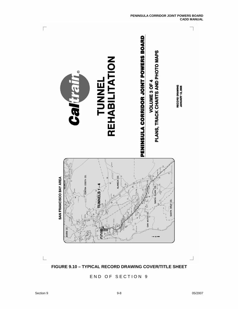
PENINSULA CORRIDOR JOINT POWERS BOARD CADD MANUAL
Section 9 9-8 05/2007
FIGURE 9.10 – TYPICAL RECORD DRAWING COVER/TITLE SHEET
E N D O F S E C T I O N 9

PENINSULA CORRIDOR JOINT POWERS BOARD CADD MANUAL
Section 10 10-i 05/2007
SECTION 10 CONTRACT DRAWING SUBMITTALS
CONTENTS
PART TITLE PAGE ______________________________________________________________________ 10.1 GENERAL 10-1 10.2 DRAWING FILE PREPARATION 10-1
10.3 DRAWING FILE AUDITS 10-2
10.4 SUBMITTALS 10-2
FIGURES 10.1 EXTERNAL REFERENCE DIALOG BOX WITH SETTINGS TO USE 10-1 10.2 AUTOCAD’S ETRANSMIT DIALOG BOXES WITH RECOMMENDED SETTINGS 10-4 10.3 DISC LABELED WITH A PERMANENT MARKER 10-5 10.4 STANDARD DISC LABEL 10-5

PENINSULA CORRIDOR JOINT POWERS BOARD CADD MANUAL
Section 10 10-1 05/2007
SECTION 10 CONTRACT DRAWING SUBMITTALS
10.1 GENERAL
As drawings for a project are developed, designers shall periodically submit the drawing set(s) and associated CADD files for review and comment. If required, contractors shall submit as-built and/or record drawings as well after a project has been constructed. PCJPB’s engineering staff will review the drawings for design, and the CADD Department will review (audit) the CADD files for conformance to the criteria set out in this Manual. All contract drawing submittals to PCJPB shall consist of both hardcopy and electronic media, which shall conform to the requirements of this Section.
10.2 DRAWING FILE PREPARATION
If any project CADD files submitted to PCJPB reference external files, they shall do so using the settings shown in Figure 10.1. The Reference Type shall be set to “Overlay” and the Path Type to “No path” in all cases. (See Subpart 3.4.3.) Reference files shall not be bound to the referencing file. All required reference files shall be referenced directly by the referencing file. Nested reference files (reference files that are themselves referenced by other reference files) will not be allowed. All nonpertinent reference files shall be detached from project CADD files prior to their submittal.
Submitted CADD files shall be purged of all unused blocks, layers, styles, layouts, etc. before submission. Any graphic entities not pertinent to the drawings shall be eliminated from the files. No path names shall be associated with the CADD files, whether with font files, menus or reference files. All viewports shall be locked.
FIGURE 10.1 - EXTERNAL REFERENCE DIALOG BOX WITH SETTINGS TO USE

PENINSULA CORRIDOR JOINT POWERS BOARD CADD MANUAL
Section 10 10-2 05/2007
10.3 DRAWING FILE AUDITS
Consultants submitting CADD files to PCJPB shall audit them and correct any problems found prior to submittal. Submittals will then be subject to a further audit by PCJPB’s CADD Department. PCJBP will check a sample of the drawings in each submittal for conformance to the criteria set out in this Manual. Autodesk’s CAD Standards checking tool used in conjunction with PCJPB’s drawing standards files (CIVL_UNITS.dws and ARCH_UNITS.dws) can assist in checking project CADD files for compliance with PCJPB’s CADD standards. This tool, however, is limited to verifying dimension styles, text styles and line types only. Use CIVL_UNITS.dws for checking drawing files with units for length set to type decimal and the insertion scale variable set to feet. Use ARCH_UNITS.dws for checking drawing files with units for length set to type architectural and the insertion scale variable set to inches. These drawing standards files are available for downloading on PCJPB’s ftp site.
10.4 SUBMITTALS
10.4.1 General
Early on in the design phase, at about the 15% or 20% stage of completion, designers shall submit their work to PCJPB’s CADD Department for an audit of the CADD files. Pdf files need not be included in this submittal, but in all other respects it shall conform to the criteria laid out in this Section. Copies of subsequent submittals shall go to both PCJPB’s CADD and Document Control Departments as discussed below. Electronic submittals shall be made on CDs or DVDs, which shall be delivered in standard jewel cases. For each submittal, two identical sets of the project CADD files shall be provided, each set on its own disc(s). One set shall go to PCJPB’s Document Control Department and the other to PCJPB’s CADD Department. The Document Control and CADD Departments shall also each receive a copy of the plot set(s) derived from the digital files. Drawings submitted for Issued for Bid and subsequent submittals shall bear design professional stamps and signatures. 10.4.2 Electronic Submittals
Only those files necessary to generate the drawings in the accompanying plot set(s) shall be included in electronic submittals to the CADD Department. All the submitted CADD files--drawing files and reference files—and their subsidiary files shall be placed on the disc(s) in one directory. If there are multiple plot sets in the submittal, the files for each plot set shall be placed in their own directory.
If electronic stamps and signatures are used, they shall be externally referenced into the CADD file layouts. Electronic stamps and signatures shall NOT be inserted as blocks or images into the CADD file layouts! They may be referenced as AutoCAD files/blocks or as image files. In the latter case, the electronic stamp and signature for each design professional may be brought together in a single image file. Regardless of which method is used, the stamp and signature file(s) for each design professional signing drawings in a project

PENINSULA CORRIDOR JOINT POWERS BOARD CADD MANUAL
Section 10 10-3 05/2007
shall be submitted along with the project’s CADD files and externally referenced into their layouts as appropriate. Submitted CADD files shall be in native AutoCAD drawing file format. Compressed files will not be accepted. The easiest way to prepare digital files for submittal is by means of AutoCAD’s eTransmit utility. See Figure 10.2 for the preferred settings to use. In addition to the project CADD files, a .pdf file for each plot set in the submittal shall also be included. These .pdf files shall contain all the drawings in their respective plot sets. Drawings shall be arranged in the .pdf file(s) as they are in the accompanying plot set(s) and shall all be correctly aligned in the landscape orientation. Drawings in the .pdf files, except for Cover/Title sheets, shall be in black and white and grey only. Electronic submittals shall be made on CD-Rs or DVD-Rs only. Recordable discs are mandatory for electronic submittals. PCJPB will not accept submittals on Rewritable discs (CDRWs, DVDRWs). Discs shall be labeled using either a permanent marker or a standard printed CD/DVD label. They shall be clearly marked with the following information: project name, contract number, submittal phase, date of submittal and the name of the consultant making the submittal. See Figures 10.3 and 10.4.
Submittals shall be compatible with Microsoft’s Windows XP operating system or whatever operating system PCJPB is currently using at the time of submittal.
10.4.3 Hardcopy Submittals
Plot sets shall include the Cover/Title sheet and be punched and bound with Chicago screws. Plotted drawings, except for Cover/Title sheets, shall be in black and white and grey only. See Part 3.6. Full-size drawings to be wet stamped and submitted shall be plotted on 20 lb. bond or better using an HP DesignJet plotter or equivalent and trimmed to 34” x 22” (ANSI D size). Scanned, half-size reductions of original wet stamped drawings shall be printed on 11” x 17” (ANSI B size) sheets of 20 lb. bond or better using an HP LaserJet printer or equivalent. Interim submittal drawing sets shall be plotted half-size on 11” x 17” (ANSI B size) sheets of 20 lb. bond or better using an HP LaserJet printer or equivalent.

PENINSULA CORRIDOR JOINT POWERS BOARD CADD MANUAL
Section 10 10-4 05/2007
FIGURE 10.2 - AUTOCAD’S ETRANSMIT DIALOG BOXES WITH RECOMMENDED SETTINGS
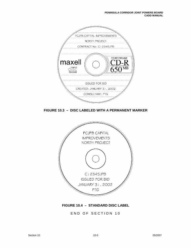
PENINSULA CORRIDOR JOINT POWERS BOARD CADD MANUAL
Section 10 10-5 05/2007
FIGURE 10.3 – DISC LABELED WITH A PERMANENT MARKER
FIGURE 10.4 – STANDARD DISC LABEL
E N D O F S E C T I O N 1 0

PENINSULA CORRIDOR JOINT POWERS BOARD CADD MANUAL
Appendix 1 A1-i 05/2007 Discipline Characters
APPENDIX 1
DISCIPLINE CHARACTERS
A ARCHITECTURAL B GENERAL C CIVIL E ELECTRICAL F FIRE PROTECTION G GEOTECHNICAL J STANDARD BLOCKS L LANDSCAPE M MECHANICAL P PLUMBING Q COMMUNICATIONS S STRUCTURAL T TRACK WORK U UTILITIES V SURVEY W OVERHEAD CONTACT SYSTEM Y TRACTION POWER Z SYSTEM GENERAL

PENINSULA CORRIDOR JOINT POWERS BOARD CADD MANUAL
Appendix 2 A2-i 05/2007 Civil Drawing Organization for a Hypothetical Project
APPENDIX 2 CIVIL DRAWING ORGANIZATION FOR A
HYPOTHETICAL PROJECT
The organization shown assumes that all drawings were developed during one design phase and submitted to PCJPB in one package for construction in one construction phase.
Typical Project Drawings
• General Civil Notes, Symbols and Abbreviations
• Existing Conditions/Demolition Plans
• Site Plans
• Utility Plans
• Grading and Drainage
• Pavement Plans
• Construction Staging
• Signing and Marking
• Traffic Signal
• Details, Cross Sections, Misc. Information

PENINSULA CORRIDOR JOINT POWERS BOARD CADD MANUAL
Appendix 3 A3-i 05/2007 Layer Names
APPENDIX 3 LAYER NAMES
Layer names shall conform to the format given in the U. S. National CAD Standard. Exceptions to this requirement are the AutoCAD Land Development Desktop and Civil 3D generated alignment and profile layer names. See the layer name examples in the table below. For more information, go to the National CAD Standard website at www.nationalcadstandard.org. The general National CAD Standard layer name format is shown below. Layer names shall be in capital letters. For PCJPB’s discipline characters, refer to Appendix 1. Minor and user-defined group abbreviations are interchangeable. Only applicable layers shall be used. Empty layers shall be purged from all contract drawing files before submittal.
Optional Discipline Modifier XX-XXXX-XXXX-XXXX-X
Discipline Character Major Group Optional Minor Group Optional User-defined Group
Optional Status (Phase) Code
LAYER NAME EXAMPLES
LAYER APPLICATION/MEANING
CIVIL
C-TOPO-MINR Topography: minor contours
C-TOPO-MAJR Topography: major contours
C-PROP-LINE Property boundary: property lines, survey benchmarks, property corners
C-BLDG Buildings and primary structures C-SITE Key plan (site plan)
C-PVMT-CONC Pavement: concrete
C-RAIL-XXXX-TRAK Railroad: track (XXXX = the track’s designation (MT-1, MT-2, MT-3, etc.))

PENINSULA CORRIDOR JOINT POWERS BOARD CADD MANUAL
Appendix 3 A3-ii 05/2007 Layer Names
LAYER APPLICATION/MEANING
C-RAIL-XXXX-PBASE Railroad: XXXX track profile grid base
C-RAIL-XXXX-PEGC Railroad: XXXX track profile existing ground centerline
C-RAIL-XXXX-PEGCT Railroad: XXXX track profile existing ground centerline station text
C-RAIL-XXXX-PEGL Railroad: XXXX track profile existing ground offset left
C-RAIL-XXXX-PEGLT Railroad: XXXX track profile existing ground left station text
C-RAIL-XXXX-PEGR Railroad: XXXX track profile existing ground offset right
C-RAIL-XXXX-PEGRT Railroad: XXXX track profile existing ground right station text
C-RAIL-XXXX-PFGL Railroad: XXXX track profile finish grade offset left
C-RAIL-XXXX-PFGR Railroad: XXXX track profile finish grade offset right
C-RAIL-XXXX-PFGC Railroad: XXXX track profile finish grade centerline
C-RAIL-XXXX-PFGCT Railroad: XXXX track profile finish grade centerline text
C-RAIL-XXXX-PGRID Railroad: XXXX track profile grid
C-RAIL-XXXX-PGRIDT Railroad: XXXX track profile grid text
C-RAIL-XXXX-STAEQU Railroad: XXXX track station equations
C-RAIL-XXXX-STALBL Railroad: XXXX track station labels
C-RAIL-XXXX-STAPTS Railroad: XXXX track station points
C-RAIL-XXXX-PVGRID Railroad: XXXX track profile vertical grid base
STRUCTURAL
S-FNDN-DETL Foundation: detail view
S-BLDG-FMNG Buildings and primary structures: framing
ARCHITECTURAL
A-GLAZ Glazing
A-ANNO-DIMS Annotation: dimensions
A-FLOR-OTLN Floor: outline
A-WALL-FIRE Wall: fire
AD-WALL Architectural demolition: walls
ELECTRICAL
E-LITE Lighting
E-GRND-CIRC Ground system: circuits
E-SITE-UNDR Site: underground lines
E-LEGN Legend of symbols

PENINSULA CORRIDOR JOINT POWERS BOARD CADD MANUAL
Appendix 4 A4-i 05/2007 PCJPB Pen Mapping
APPENDIX 4 PCJPB PEN MAPPING
Consultants are solely responsible for the production and appearance of their hardcopy submittals. The Color-dependent Plot Style Table file PCJPB.ctb is provided to support the consistent plotting of PCJPB project drawings. It shall be used for the plotting of PCJPB project drawings in all cases. The pen assignments it contains are shown in the table below. All entity color and line type values in project CADD files shall be set to "ByLayer”. Note that, in addition to colors 250 through 254, colors 8 and 9 may be assigned to layers when it is desired that the detail on them appear as if screened. Colors 8 and 9 produce true screened blacks as opposed to grays and may give better results when drawings are xeroxed or scanned and the scans plotted. See PCJPB’s Pen Mapping/Color Chart at the end of this Manual.
PCJPB Pen Mapping Plotter Output: AutoCAD Color
Name (Screen Color)
Line Weight (mm) % Fill Color
1 (red) 0.15 100 7 (black)
2 (yellow) 0.25 100 7 (black)
3 (green) 0.35 100 7 (black)
4 (cyan) 0.50 100 7 (black)
5 (blue) 0.70 100 7 (black)
6 (magenta) 0.90 100 7 (black)
7 (black/white) 0.35 100 7 (black)
8 0.25 40 7 (black)
9 0.35 40 7 (black)
10 0.15 100 1 (red)
11 0.25 100 7 (black)
12 0.35 100 3 (green)
13 0.50 100 4 (cyan)
14 0.70 100 5 (blue)
15 0.90 100 6 (magenta)

PENINSULA CORRIDOR JOINT POWERS BOARD CADD MANUAL
Appendix 4 A4-ii 05/2007 PCJPB Pen Mapping
PCJPB Pen Mapping Plotter Output: AutoCAD Color
Name (Screen Color)
Line Weight (mm) % Fill Color
16 Default 100 16
17 0.50 100 17
18 Default 100 18
19 Default 100 19
20 0.50 100 1 (red)
21 Default 100 21
22 Default 100 22
23 Default 100 23
24 Default 100 24
25 Default 100 25
26 Default 100 26
27 0.70 100 17
28 Default 100 28
29 Default 100 29
30 0.50 100 30
31 0.80 100 30
32 1.00 100 30
33 Default 100 33
34 Default 100 34
35 Default 100 35
36 1.00 100 17
37 1.40 100 17
38 Default 100 38
39 Default 100 39
40 0.80 100 40
41 Default 100 41
42 1.00 100 40
43 1.40 100 40
44 0.50 100 40
45 Default 100 45
46 Default 100 46

PENINSULA CORRIDOR JOINT POWERS BOARD CADD MANUAL
Appendix 4 A4-iii 05/2007 PCJPB Pen Mapping
PCJPB Pen Mapping Plotter Output: AutoCAD Color
Name (Screen Color)
Line Weight (mm) % Fill Color
47 Default 100 47
48 Default 100 48
49 Default 100 49
50 0.80 100 2 (yellow)
51 1.00 100 2 (yellow)
52 0.50 100 2 (yellow)
53 1.40 100 2 (yellow)
54 Default 100 54
55 Default 100 55
56 Default 100 56
57 Default 100 57
58 Default 100 58
59 Default 100 59
60 2.00 100 255
61 0.90 100 255
62 Default 100 62
63 Default 100 63
64 Default 100 64
65 1.58 100 255
66 Default 100 66
67 Default 100 67
68 Default 100 68
69 Default 100 69
70 Default 100 70
71 Default 100 71
72 Default 100 72
73 Default 100 73
74 Default 100 74
75 Default 100 75
76 Default 100 76
77 Default 100 77

PENINSULA CORRIDOR JOINT POWERS BOARD CADD MANUAL
Appendix 4 A4-iv 05/2007 PCJPB Pen Mapping
PCJPB Pen Mapping Plotter Output: AutoCAD Color
Name (Screen Color)
Line Weight (mm) % Fill Color
78 Default 100 78
79 Default 100 79
80 0.50 100 3 (green)
81 Default 100 81
82 0.70 100 3 (green)
83 Default 100 83
84 Default 100 84
85 Default 100 85
86 0.50 100 94
87 Default 100 87
88 Default 100 88
89 Default 100 89
90 1.00 100 3 (green)
91 Default 100 91
92 Default 100 92
93 Default 100 93
94 0.70 100 94
95 Default 100 95
96 1.00 100 94
97 Default 100 97
98 Default 100 98
99 Default 100 99
100 1.40 100 3 (green)
101 Default 100 101
102 Default 100 102
103 Default 100 103
104 Default 100 104
105 Default 100 105
106 1.40 100 94
107 Default 100 107
108 Default 100 108

PENINSULA CORRIDOR JOINT POWERS BOARD CADD MANUAL
Appendix 4 A4-v 05/2007 PCJPB Pen Mapping
PCJPB Pen Mapping Plotter Output: AutoCAD Color
Name (Screen Color)
Line Weight (mm) % Fill Color
109 Default 100 109
110 Default 100 110
111 0.50 100 111
112 Default 100 112
113 0.80 100 111
114 Default 100 114
115 Default 100 115
116 Default 100 116
117 Default 100 117
118 Default 100 118
119 Default 100 119
120 Default 100 120
121 Default 100 121
122 Default 100 122
123 1.00 100 111
124 Default 100 124
125 1.40 100 111
126 Default 100 126
127 Default 100 127
128 Default 100 128
129 Default 100 129
130 0.70 100 4 (cyan)
131 0.50 100 131
132 1.00 100 4 (cyan)
133 1.00 100 131
134 0.50 100 4 (cyan)
135 Default 100 135
136 Default 100 136
137 Default 100 137
138 Default 100 138
139 Default 100 139

PENINSULA CORRIDOR JOINT POWERS BOARD CADD MANUAL
Appendix 4 A4-vi 05/2007 PCJPB Pen Mapping
PCJPB Pen Mapping Plotter Output: AutoCAD Color
Name (Screen Color)
Line Weight (mm) % Fill Color
140 1.40 100 4 (cyan)
141 1.00 100 131
142 Default 100 142
143 1.40 100 131
144 0.70 100 5 (blue)
145 Default 100 145
146 Default 100 146
147 Default 100 147
148 Default 100 148
149 Default 100 149
150 0.50 100 5 (blue)
151 Default 100 151
152 1.00 100 5 (blue)
153 Default 100 153
154 Default 100 154
155 Default 100 155
156 Default 100 156
157 Default 100 157
158 Default 100 158
159 Default 100 159
160 1.40 100 5 (blue)
161 Default 100 161
162 Default 100 162
163 Default 100 163
164 Default 100 164
165 Default 100 165
166 Default 100 166
167 Default 100 167
168 Default 100 168
169 Default 100 169
170 Default 100 170

PENINSULA CORRIDOR JOINT POWERS BOARD CADD MANUAL
Appendix 4 A4-vii 05/2007 PCJPB Pen Mapping
PCJPB Pen Mapping Plotter Output: AutoCAD Color
Name (Screen Color)
Line Weight (mm) % Fill Color
171 Default 100 171
172 Default 100 172
173 Default 100 173
174 Default 100 174
175 Default 100 175
176 Default 100 176
177 Default 100 177
178 Default 100 178
179 Default 100 179
180 Default 100 180
181 0.50 100 181
182 Default 100 182
183 0.70 100 181
184 Default 100 184
185 1.00 100 181
186 Default 100 186
187 1.40 100 181
188 Default 100 188
189 Default 100 189
190 0.50 100 190
191 Default 100 191
192 0.70 100 190
193 Default 100 193
194 Default 100 194
195 Default 100 195
196 Default 100 196
197 Default 100 197
198 Default 100 198
199 Default 100 199
200 1.00 100 6 (magenta)
201 Default 100 201

PENINSULA CORRIDOR JOINT POWERS BOARD CADD MANUAL
Appendix 4 A4-viii 05/2007 PCJPB Pen Mapping
PCJPB Pen Mapping Plotter Output: AutoCAD Color
Name (Screen Color)
Line Weight (mm) % Fill Color
202 1.00 100 190
203 Default 100 203
204 1.40 100 190
205 Default 100 205
206 Default 100 206
207 Default 100 207
208 Default 100 208
209 Default 100 209
210 0.70 100 6 (magenta)
211 Default 100 211
212 1.40 100 6 (magenta)
213 Default 100 213
214 Default 100 214
215 Default 100 215
216 Default 100 216
217 Default 100 217
218 Default 100 218
219 Default 100 219
220 1.00 100 1 (red)
221 Default 100 221
222 0.50 100 6 (magenta)
223 Default 100 223
224 Default 100 224
225 Default 100 225
226 Default 100 226
227 Default 100 227
228 Default 100 228
229 Default 100 229
230 1.40 100 1 (red)
231 Default 100 231
232 Default 100 232

PENINSULA CORRIDOR JOINT POWERS BOARD CADD MANUAL
Appendix 4 A4-ix 05/2007 PCJPB Pen Mapping
PCJPB Pen Mapping Plotter Output: AutoCAD Color
Name (Screen Color)
Line Weight (mm) % Fill Color
233 Default 100 233
234 Default 100 234
235 Default 100 235
236 Default 100 236
237 Default 100 237
238 Default 100 238
239 Default 100 239
240 0.80 100 1 (red)
241 Default 100 241
242 Default 100 242
243 Default 100 243
244 Default 100 244
245 Default 100 245
246 Default 100 246
247 Default 100 247
248 Default 100 248
249 Default 100 249
250 0.40 100 250
251 0.40 100 251
252 0.40 100 252
253 0.40 100 253
254 0.40 100 254
255 0.40 100 255

PENINSULA CORRIDOR JOINT POWERS BOARD CADD MANUAL
Appendix 5 A5-i 05/2007 PCJPB’S Aerial Topographic Files
APPENDIX 5
PCJPB’S AERIAL TOPOGRAPHIC FILES
Periodically, PCJPB contracts to have the Caltrain Corridor flown and mapped. The resulting map consists of a number of AutoCAD drawing files. Each of these topographic files (or tiles) covers an area of 4,000 by 4,000 feet on the ground and is named for the northing and easting of its insertion point. They are intended for use as backgrounds for PCJPB design drawings. This Appendix gives layer, block and line type information for these files. In the following list, (ATT) denotes an attributed block.

PENINSULA CORRIDOR JOINT POWERS BOARD CADD MANUAL
Appendix 5 A5-ii 05/2007 PCJPB’S Aerial Topographic Files

PENINSULA CORRIDOR JOINT POWERS BOARD CADD MANUAL
Appendix 5 A5-iii 05/2007 PCJPB’S Aerial Topographic Files

PENINSULA CORRIDOR JOINT POWERS BOARD CADD MANUAL
Appendix 5 A5-iv 05/2007 PCJPB’S Aerial Topographic Files

PENINSULA CORRIDOR JOINT POWERS BOARD CADD MANUAL
Appendix 5 A5-v 05/2007 PCJPB’S Aerial Topographic Files
Do not modify PCJPB’s aerial topography files. Specifically, do not re-map the layer colors, change line types, etc. within the files themselves. Instead, use the AutoCAD XR command to attach them to design files with the overlay option as required. Then re-map the colors, change line types, etc. as desired in the design files using the Layer Properties Manager.

PENINSULA CORRIDOR JOINT POWERS BOARD CADD MANUAL
Appendix 6 A6-i 05/2007 PCJPB Line Types
APPENDIX 6 PCJPB LINE TYPES
FIGURE A6.1 - LINE TYPES CONTAINED IN THE FILE PCJPB.LIN

PENINSULA CORRIDOR JOINT POWERS BOARD CADD MANUAL
Appendix 6 A6-ii 05/2007 PCJPB Line Types
FIGURE A6.2 - LINE TYPES CONTAINED IN THE FILE PCJPB.LIN (CONTINUED)

PENINSULA CORRIDOR JOINT POWERS BOARD CADD MANUAL
Appendix 6 A6-iii 05/2007 PCJPB Line Types
FIGURE A6.3 - LINE TYPES CONTAINED IN THE FILE PCJPB.LIN (CONTINUED)
Notes to PCJPB.lin PCJPB updates PCJPB.lin periodically. Each version is dated, with the date coded as: YYYYMMDD. As of this writing, the current version of PCJPB.lin is PCJPB-20070216.lin. Certain PCJPB line types are based on shapes contained in the file PCJPB2.shx. This file must be present for AutoCAD to display lines of these types correctly. FENCE JPB is used to symbolize PCJPB inter-track and station fencing. MATCHFS is used to draw match lines when the CADD file line type scale is set to one (1). PCJPB.lin also contains the line types MATCH10, MATCH20, MATCH40, MATCH50 AND MATCH100 which are for use in CADD files with the line type scale set to 10, 20, 40, etc. “OH” stands for “OVERHEAD”. The “PL” in “JPB PL” stands for “PIPELINE”. Compound Line Types The line types illustrated in Figures A6.4 and A6.5 below are not contained in the PCJPB.lin file and must be created. For symbolizing a storm drain over 18” in diameter, use a polyline of line type UT STORM DRAIN OVER 18 as a fill in conjunction with a
PENINSULA CORRIDOR JOINT POWERS BOARD CADD MANUAL
Appendix 6 A6-iv 05/2007 PCJPB Line Types
casing of two parallel lines. The width of the compound line in model space shall equal the diameter of the storm drain it symbolizes. To create the others, superimpose lines of the indicated type over a line of type RR10, RR20, etc. as appropriate. The track symbol will generally be gray and the superimposed lines black.
FIGURE A6.4 - SPECIAL LINE TYPES
PENINSULA CORRIDOR JOINT POWERS BOARD CADD MANUAL
Appendix 6 A6-v 05/2007 PCJPB Line Types
FIGURE A6.5 - SPECIAL LINE TYPES (CONTINUED)

PENINSULA CORRIDOR JOINT POWERS BOARD CADD MANUAL
Appendix 7 A7-i 05/2007
APPENDIX 7
NOT USED

PENINSULA CORRIDOR JOINT POWERS BOARD CADD MANUAL
Appendix 8 A8-i 05/2007 Block Library
APPENDIX 8 BLOCK LIBRARY
PENDING

PENINSULA CORRIDOR JOINT POWERS BOARD CADD MANUAL
Appendix 9 A9-i 05/2007 Metric drawings
APPENDIX 9 METRIC DRAWINGS
The following information may be helpful should a PCJPB project ever involve metric drawings. Since paper space units are in millimeters in metric drawings, PCJPB AutoCAD files/blocks (for example, JPBBDR.dwg) must be scaled by a factor of 25.40 (there are 25.40 millimeters to the inch) when inserting or referencing them into the layouts of metric CADD files. Doing this converts their dimensions into millimeters. Sizing Text in Metric Drawings For any text size, multiply the desired height of plotted text by the appropriate scale factor given in the following table to get the corresponding text height in model space.
Desired Height of Text on Full-size
Plots:
3.175 mm (1/8")
3.556 mm (0.140")
4.7625 mm (3/16")
6.35 mm (1/4")
Scale of View
Scale Factor to
Apply
Height of Text in Model Space in Meters
Height of Text in Model Space in Meters
Height of Text in Model Space in Meters
Height of Text in Model Space in Meters
1:100 0.1 0.3175 0.3556 0.47625 0.635
1:200 0.2 0.635 0.7112 0.9525 1.27
1:250 0.25 0.79375 0.889 1.190625 1.5875
1:500 0.5 1.5875 1.778 2.38125 3.175
1:1,000 1 3.175 3.556 4.7625 6.35
1:2,000 2 6.35 7.112 9.525 12.7
1:5,000 5 15.875 17.78 23.8125 31.75
1:6,000 6 19.05 21.336 28.575 38.1
For use in AutoCAD files with linear units set to type decimal and the insertion scale variable set to meters.
TABLE A9.1 – SELECTED METRIC SCALES, SCALE FACTORS AND TEXT
HEIGHTS

PENINSULA CORRIDOR JOINT POWERS BOARD CADD MANUAL
Appendix 9 A9-ii 05/2007 Metric drawings
Scaling Views in Metric AutoCAD Drawings When scaling views in metric AutoCAD drawings, keep in mind that the paper space unit is millimeters and the model space unit is meters. Remembering this, scale factors are then easy to calculate. A couple of examples follow to illustrate. When using the zoom/scale command to scale detail in a viewport, AutoCAD asks for the desired ratio of paper space units to model space units, or:
Paper Space units / Model Space units xp For a scale of 1:100 using the zoom/scale command:
Paper Space units Model Space units
1:100
1 millimeter : 100 millimeters
1 mm : 0.10 m
1 / 1/10 xp
10 xp Or ten paper space units to one model space unit (10 millimeters to one meter.) For a scale of 1:2,000:
Paper Space units Model Space units
1:2,000
1 millimeter : 2,000 millimeters
1 mm : 2.000 m
1/2 xp Or one paper space unit to two model space units (1 millimeter to 2 meters.)

PENINSULA CORRIDOR JOINT POWERS BOARD CADD MANUAL
Appendix 9 A9-iii 05/2007 Metric drawings
Metric Scales When choosing metric scales, the table below may be used to find the metric scale that will produce a plot approximating in appearance the plot of a drawing drawn and plotted to the listed common English engineering scale.
Common English Engineering Scale to
Approximate
Scale of Metric Drawing Viewport/Plot
Metric Drawing Viewport’s/Plot’s Scale in
English Units
1”= 10’ 1:100 1"= 8.33'
--- 1:200 1"= 16.67'
1”= 20’ 1:250 1"= 20.83'
1”= 40’ 1:500 1"= 41.67'
1”= 80’ 1:1,000 1"= 83.33'
--- 1:2,000 1"= 166.67'
1”= 400’ 1:5,000 1"= 416.66'
1”= 500’ 1:6,000 1"= 500.00'
TABLE A9.2 – METRIC/ENGLISH PLOTTING SCALE COMPARISON CHART Dimensioning Metric Drawings Created for PCJPB See Figures A9.1 through A9.5 below for the settings to use when setting up dimension styles in metric drawings created for PCJPB. See Table A9.3 for style names to use and overall scale factors to apply in the creation of these styles.

PENINSULA CORRIDOR JOINT POWERS BOARD CADD MANUAL
Appendix 9 A9-iv 05/2007 Metric drawings
FIGURE A9.1 – METRIC DIMENSION STYLE SETTINGS LINES
FIGURE A9.2 – METRIC DIMENSION STYLE SETTINGS SYMBOLS AND ARROWS

PENINSULA CORRIDOR JOINT POWERS BOARD CADD MANUAL
Appendix 9 A9-v 05/2007 Metric drawings
FIGURE A9.3 – METRIC DIMENSION STYLE SETTINGS TEXT
FIGURE A9.4 – METRIC DIMENSION STYLE SETTINGS FIT

PENINSULA CORRIDOR JOINT POWERS BOARD CADD MANUAL
Appendix 9 A9-vi 05/2007 Metric drawings
FIGURE A9.5 - METRIC DIMENSION STYLE SETTINGS PRIMARY UNITS
Scale Dimension Style Scale for Dimension Features
Use overall scale of:
1:100 100 METRIC 100 1:200 200 METRIC 200
1:250 250 METRIC 250 1:500 500 METRIC 500
1:1,000 1000 METRIC 1,000
1:2,000 2000 METRIC 2,000 1:5,000 5000 METRIC 5,000 1:6,000 6000 METRIC 6,000
TABLE A9.3 - DIMENSION STYLES DERIVED FROM THE METRIC STYLE

PENINSULA CORRIDOR JOINT POWERS BOARD CADD MANUAL
Appendix 10 A10-i 05/2007 PCJPB CADD Requirements for Signal Drawings
APPENDIX 10 PCJPB CADD REQUIREMENTS FOR SIGNAL
DRAWINGS GENERAL Signal CADD files are living documents that must be properly maintained to ensure the integrity of the signal system. Duplicate file copies increase the possibility of misleading or inaccurate drawings being distributed to construction or maintenance forces. Files shall not be duplicated without the authority of the Chief Engineer. Drawings shall be produced utilizing a MicroStation 2-dimensional format. Contractors shall adhere to the FORMAT REQUIREMENTS as indicated later in this document. Contractors shall reimburse PCJPB for all costs associated with correcting format discrepancies. Prior to beginning a signal design project, CADD files should be requested from: A general description of the project(s) shall be submitted to Southwest Signal Engineering (SWE) along with specific milepost limits. Along with the current CADD files, SWE shall furnish a border file (JPBBRDR.RFC), a cell library containing the symbols to be utilized on PCJPB drawings and any pertinent TYPICAL and/or REFERENCE files that are available. Borders and cells shall not be scaled up or down. Files shall be provided to the contractor on Colorado QIC-80 format tape, ZIP Drive (1GB) or floppy disk. Contractor should specify the various mediums available for use in transferring files. Upon Completion of the design, the contractor shall return the CADD files and an ll” x 17” hardcopy of each file to SWE. The contractor shall include an itemized list of the files returned. The list shall categorize files by NEW FILES, MODIFIED FILES and DELETED FILES. If the contractor is required to furnish AS-BUILT files, the contractor shall provide SWE with CADD files of drawings that are distributed for construction and then provide corrected CADD files upon completion of the project. Drawings, borders and cells shall not be scaled up or down. New cells shall not be created without proper authority. Where designs are created for “Bid Documents” the contractor’s border shall be “scaled” to equal the JPBBRDR.RFC border. The “X=out/0=in” convention shall be used on contract drawings. Contractor borders shall be “REFERENCED ATTACHED’ to facilitate removal. Construction drawings created for PCJPB maintenance forces shall utilize RED=IN/YELLOW=OUT color conventions. File names shall be 8-characters long followed by a 3-character extension. (EXAMPLE: PN029_20.C01 and PN029_20.M02 would be the file names for sheet 1 and sheet 2 of a location on the Peninsula Subdivision at Milepost 29.20.) The “C” in the file extension indicates that the drawing contains CONSTRUCTION elements; an “M” file extension

PENINSULA CORRIDOR JOINT POWERS BOARD CADD MANUAL
Appendix 10 A10-ii 05/2007 PCJPB CADD Requirements for Signal Drawings
indicates that the file is a MAINTENANCE plan; a “B” file extension indicates the file has “FIELD VERIFY” elements; and a “T” file extension indicates the file is temporary and will be deleted upon completion of construction. EXAMPLES: PN003_30.C09 Construction Drawing PN041_00.M04 Maintenance Drawing PN011_20.T03 Temporary Drawing PN021_00.B01 Field Verification Required FORMAT REQUIREMENTS The following drawing conventions shall be used on ALL signal design files:
1. “TYPICAL” files shall be used if available. SWE will furnish appropriate “TYPICAL” files.
2. All new design files shall be SINGLE sheet, with lower left corner starting at
XY=0,0 (GLOBAL ORIGIN.)
3. All graphics will be placed on the appropriate levels as follows:
LEVEL DESCRIPTION 1 Circuits 2 Black Boxes and shapes (no fill) 3 Yellow shapes filled solid 4-7 Reserved for future use 8 Wire size 9 Rack location number 10 Wire nomenclature 11 Relay qualifier 12-13 Not used 14 Relay contact qualifier 15 Contact number 16 Crossing DOT number 17-25 Not used 26 Title block 27-63 Reserved
4. SAVE SETTINGS as follows:
a) Levels 1-39 ON / Levels 40-63 OFF b) ENTER DATA FIELDS turned off (all views) c) SNAP and GRID locks ON, LEVEL lock OFF d) TX=0.08 (Text Size) e) FT=0 (Font) f) Justification=CC g) LINE SPACING=0.05 h) WT=1 (Line Weight)

PENINSULA CORRIDOR JOINT POWERS BOARD CADD MANUAL
Appendix 10 A10-iii 05/2007 PCJPB CADD Requirements for Signal Drawings
i) LV=1 (Active Level) j) AS=1 (Active Scale) k) AA=0 (Active Angle) l CO=0 (Color) m) Left screen (view #5) – view of complete drawing n) Right screen (view #1) – view of title block area
5. The design file name shall be placed in the lower left-hand corner of the design file border. EXAMPLE: PN029_00.B01
6. On SHEET 1 of each drawing the track layout will be shown. Signal block
circuits and other circuits extending to adjacent locations shall be placed on this sheet and the “TOADJ” cell used on each end of the sheet to reference the adjoining circuit drawing and sheet number (See example provided.)
7. Standard street width = 1 inch.
8. Distance between rails = 2/10 inch.
9. Distance between tracks = 7/10 inch center to center.
10. Track WT=5 LV=1
11. Circuits WT=2 LV=1
12. Black boxes (shapes) WT=3 LV=2
13. Wire nomenclature LV=10
14. Relay nomenclature (use appropriate cell and data fields)
15. Legend (provided on front cover reference file)
16. Revision notes (use JBNOTE cell)
17. Relay contact numbering (use contact cells and fill in enter data fields)
18. Relay information (use relay cells and fill in enter data fields)
19. Font=0 WT-1 TX=0.08 Justification=CC Line Spacing=0.05
20. All old SPTC references shall be drawn out on new CADD files.
21. All NEW circuits shall be in RED LV=1
22. All circuits to be removed shall be BLACK LV=1 with YELLOW shape LV=3
23. Existing circuits shall be BLACK LV=1

PENINSULA CORRIDOR JOINT POWERS BOARD CADD MANUAL
Appendix 10 A10-iv 05/2007 PCJPB CADD Requirements for Signal Drawings
24. Where possible the following identifiers shall be placed directly above item:
Street Names DOT Number PUC Number Engineering Stations
25. Primary Title Block Names are as follows:
Signal Circuit Plan Crossing Circuit Plan Gate Circuit Plan Program Options Plan Cable Sheet Control Point sheets shall be named for their contents.
26. The FRONT COVER SHEET shall contain an index of the drawings included in the drawing set. The index shall indicate the sheet number and corresponding title block name. The cover sheet shall indicate the drawing set name such as:
WHIPPLE AVENUE PN 24.80
DRAWING DISTRIBUTION: Drawing sets (i.e. books) shall be distributed to PCJPB forces as follows: Construction Sets: 2 ea. To PCJPB Chief Engineer 3 ea. To Amtrak’s C&S Asst. Division Engineer 4 ea. To Amtrak for construction (where applicable) Maintenance Sets: 2 ea. To PCJPB Chief Engineer 7 ea. To Amtrak
E N D O F A P P E N D I C E S

