penetration rate prediction for percussive drilling with
TRANSCRIPT
HAL Id: hal-01521017https://hal.archives-ouvertes.fr/hal-01521017
Submitted on 11 May 2017
HAL is a multi-disciplinary open accessarchive for the deposit and dissemination of sci-entific research documents, whether they are pub-lished or not. The documents may come fromteaching and research institutions in France orabroad, or from public or private research centers.
L’archive ouverte pluridisciplinaire HAL, estdestinée au dépôt et à la diffusion de documentsscientifiques de niveau recherche, publiés ou non,émanant des établissements d’enseignement et derecherche français ou étrangers, des laboratoirespublics ou privés.
Penetration rate prediction for percussive drilling withrotary in very hard rock
Nguyen van Hung, Laurent Gerbaud, R Souchal, C Urbanczyk, C Fouchard
To cite this version:Nguyen van Hung, Laurent Gerbaud, R Souchal, C Urbanczyk, C Fouchard. Penetration rate predic-tion for percussive drilling with rotary in very hard rock. Journal of Science and Technology, VietnamAcademy of Science and Technology, 2016, 54 (1), pp.133-149. �10.15625/0866-708X/54/1/5956�.�hal-01521017�
Tạp chí Khoa học và Công nghệ 54 (1) (2016) 133-149
PENETRATION RATE PREDICTION FOR PERCUSSIVE DRILLING WITH ROTARY IN VERY HARD ROCK
Nguyen Van Hung1, *, L. Gerbaud2, R. Souchal3, C. Urbanczyk4, C. Fouchard4
1Petrovietnam University, Cach mang Thang 8 Street, Baria - Vung Tau, Vietnam
2Ecole des Mines ParisTech, 60 Boulevard Saint-Michel, 75006 Paris, France 3Drillstar industries, Avenue Frédéric et Irène Joliot Curie, 64140 Lons, France
4Total, Avenue Larribau, 64000 Pau, France
*Email: [email protected]
Received: 11 March 2015; Accepted for publication: 30 November 2015
ABSTRACT
This paper is the following part of our project to predict the penetration rate for percussive drilling with rotary in very hard rock. As results in [1] have been shown that the rate of penetration was strong influent by Brazilian tensile strength and it was exist the correlation between the rate of penetration and the rock properties. Yet, the study was valid on six hard rocks in experimental result of test tricone and rotary with percussive. All relationships have been shown but the coefficient R2 is still very low. This paper will present a new relationship with high value of R2 based on previous data and also establish a mathematical relationship, numerical model to predict the penetration rate.
Key words: Hard rocks, ROP, drilling, mathematical model, numerical model.
1. INTRODUCTION TO STRESS WAVE THEORY
1.1. Longitudinal elastic waves in a rod
Consider one long rod, the cross-sectional area of which is equal to A. Let the Young’s modulus and the unit weight of the material that constitute the rod be equal to E and γ (or
density of the material, ρ , with g/γρ = ), g is the acceleration due to gravity and ν is the Poisson’s ratio. Now, let the stress along section a-a of the rod increase byσ Fig. 1. The stress increase along the section b-b can then give by xx ∆∂∂+ )/( σσ . Based on Newton’s second
law: )()( onacceleratimassforce∑ = .
Nguyen Van Hung, L.Gerbaud, R.Souchal, C.Urbanczyk, C.Fouchard
134
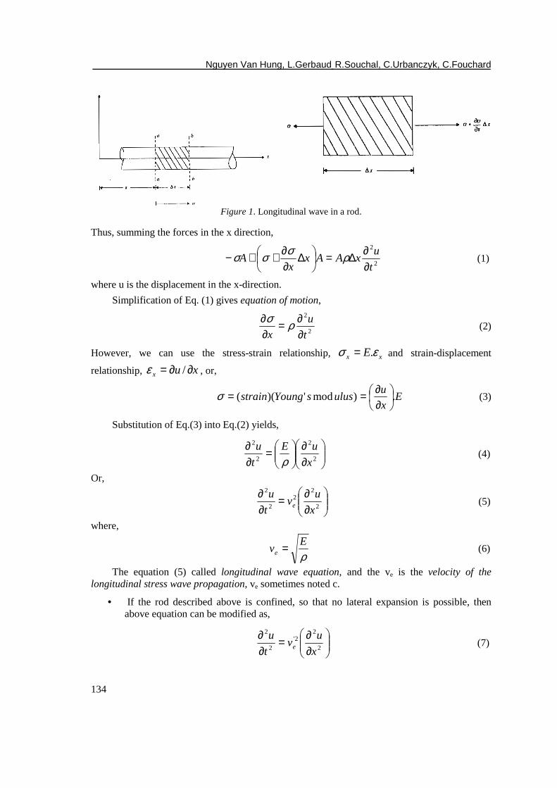
Figure 1. Longitudinal wave in a rod.
Thus, summing the forces in the x direction,
2
2
t
uxAAx
xA
∂∂∆=
∆∂∂++− ρσσσ (1)
where u is the displacement in the x-direction.
Simplification of Eq. (1) gives equation of motion,
2
2
t
u
x ∂∂=
∂∂ ρσ
(2)
However, we can use the stress-strain relationship, xx Eεσ .= and strain-displacement
relationship, xux ∂∂= /ε , or,
Ex
uulussYoungstrain .)mod')((
∂∂==σ (3)
Substitution of Eq.(3) into Eq.(2) yields,
∂∂
=∂∂
2
2
2
2
x
uE
t
u
ρ (4)
Or,
∂∂=
∂∂
2
22
2
2
x
uv
t
ue (5)
where,
ρE
ve = (6)
The equation (5) called longitudinal wave equation, and the ve is the velocity of the longitudinal stress wave propagation, ve sometimes noted c.
• If the rod described above is confined, so that no lateral expansion is possible, then above equation can be modified as,
∂∂=
∂∂
2
22'
2
2
x
uv
t
ue (7)
Penetration rate prediction for percussive drilling with rotary in very hard rock
135
where,
ρM
ve =' (8)
M = constrained modulus =)1)(21(
)1(
ννν
+−−E
.
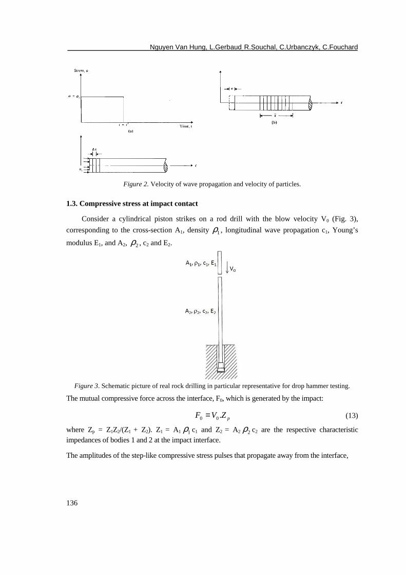
1.2. Velocity of particles in the stressed zone
It is important to differentiate between the velocity of the longitudinal wave propagation
(ve) and the velocity of the particles in the stressed zone (.
u ). In order to distinguish them,
consider a compressive stress pulse of intensely xσ and duration t’(Fig. 2a) be applied to the
end of a rod (Fig. 2b). When this pulse is applied initially, a small zone of the rod will undergo compression. With time this compression will be transmitted to successive zones. During a time interval t∆ the stress will travel through a distance tvx e∆=∆ .
At any time t>t’, a segment of the rod of length x will constitute the compressed zone. Note that,
'tvx e=
The elastic deformation of the rod then is,
( ) ( )'tvE
xE
u exx
=
=σσ
(9)
Note that u is the displacement of the end of the rod. Now, the velocity of the end of the rod and, thus, the particle velocity is,
E
v
t
uu exσ
=='
.
(10)
Substitution of Eq. (6) into Eq.(10) yields,
ρσ
ρσ
e
x
e
ex
vv
vu ==
2
.
(11)
Or
)(.
ρσ ex vu= (12)
Equation (12) shows that the particle velocity is proportional to the axial stress in the rod. The
coefficient of proportionality, ρev , is called the specific impedance of the material.
Nguyen Van Hung, L.Gerbaud, R.Souchal, C.Urbanczyk, C.Fouchard
136
Figure 2. Velocity of wave propagation and velocity of particles.
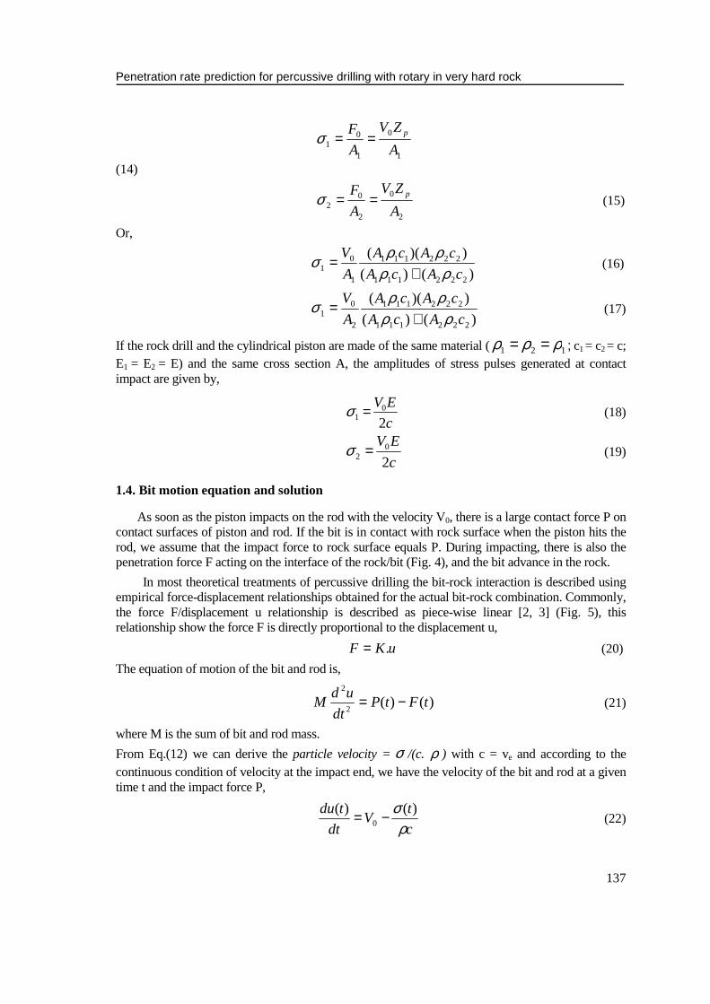
1.3. Compressive stress at impact contact
Consider a cylindrical piston strikes on a rod drill with the blow velocity V0 (Fig. 3),
corresponding to the cross-section A1, density 1ρ , longitudinal wave propagation c1, Young’s
modulus E1, and A2, 2ρ , c2 and E2.
Figure 3. Schematic picture of real rock drilling in particular representative for drop hammer testing.
The mutual compressive force across the interface, F0, which is generated by the impact:
pZVF .00 = (13)
where Zp = Z1Z2/(Z1 + Z2). Z1 = A1 1ρ c1 and Z2 = A2 2ρ c2 are the respective characteristic impedances of bodies 1 and 2 at the impact interface.
The amplitudes of the step-like compressive stress pulses that propagate away from the interface,
Penetration rate prediction for percussive drilling with rotary in very hard rock
137
1
0
1
01 A
ZV
A
F p==σ
(14)
2
0
2
02 A
ZV
A
F p==σ (15)
Or,
)()(
))((
222111
222111
1
01 cAcA
cAcA
A
V
ρρρρσ
+= (16)
)()(
))((
222111
222111
2
01 cAcA
cAcA
A
V
ρρρρσ
+= (17)
If the rock drill and the cylindrical piston are made of the same material ( 121 ρρρ == ; c1 = c2 = c; E1 = E2 = E) and the same cross section A, the amplitudes of stress pulses generated at contact impact are given by,
c
EV
20
1 =σ (18)
c
EV
20
2 =σ (19)
1.4. Bit motion equation and solution
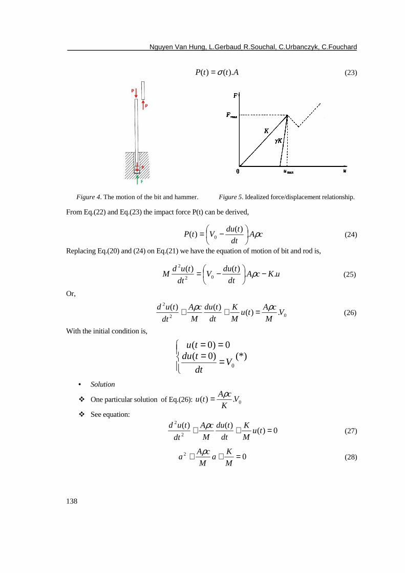
As soon as the piston impacts on the rod with the velocity V0, there is a large contact force P on contact surfaces of piston and rod. If the bit is in contact with rock surface when the piston hits the rod, we assume that the impact force to rock surface equals P. During impacting, there is also the penetration force F acting on the interface of the rock/bit (Fig. 4), and the bit advance in the rock.
In most theoretical treatments of percussive drilling the bit-rock interaction is described using empirical force-displacement relationships obtained for the actual bit-rock combination. Commonly, the force F/displacement u relationship is described as piece-wise linear [2, 3] (Fig. 5), this relationship show the force F is directly proportional to the displacement u,
uKF .= (20)
The equation of motion of the bit and rod is,
)()(2
2
tFtPdt
udM −= (21)
where M is the sum of bit and rod mass.
From Eq.(12) we can derive the particle velocity = σ /(c. ρ ) with c = ve and according to the continuous condition of velocity at the impact end, we have the velocity of the bit and rod at a given time t and the impact force P,
c
tV
dt
tdu
ρσ )()(
0 −= (22)
Nguyen Van Hung, L.Gerbaud, R.Souchal, C.Urbanczyk, C.Fouchard
138
AttP ).()( σ= (23)
Figure 4. The motion of the bit and hammer. Figure 5. Idealized force/displacement relationship.
From Eq.(22) and Eq.(23) the impact force P(t) can be derived,
cAdt
tduVtP ρ.
)()( 0
−= (24)
Replacing Eq.(20) and (24) on Eq.(21) we have the equation of motion of bit and rod is,
uKcAdt
tduV
dt
tudM ..
)()(02
2
−
−= ρ (25)
Or,
02
2
.)()()(
VM
cAtu
M
K
dt
tdu
M
cA
dt
tud ρρ =++ (26)
With the initial condition is,
(*))0(0)0(
0
====
Vdt
tdutu
• Solution
� One particular solution of Eq.(26): 0.)( VK
cAtu
ρ=
� See equation:
0)()()(
2
2
=++ tuM
K
dt
tdu
M
cA
dt
tud ρ (27)
02 =++M
Ka
M
cAa
ρ (28)
Penetration rate prediction for percussive drilling with rotary in very hard rock
139
.42
M
K
M
cA −
=∆ ρ
Case 1
- If ∆ >0 : .42
M
K
M
cA >
ρ
Equation (28) has two solutions:
−
−−
=
−
+−
=
2
4
2
4
2
2
2
1
M
K
M
cA
M
cA
a
M
K
M
cA
M
cA
a
ρρ
ρρ
Thus, Eq.(27) has two solutions:
==
ta
ta
etu
etu2
1
)(
)(
2
1
and the solution of equation of motion of bit and rod,
021 .)( 21 VK
cAeCeCtu tata ρ++=
where C1 and C2 are constants, can be determined from initial condition (*),
−
++−=
−
+=
021
21
2
021
2
1
.1)2(
.1
Vaa
aaK
cA
C
Vaa
aK
cA
C
ρ
ρ
Case 2
- If ∆ =0 : .42
M
K
M
cA =
ρ
M
cAaa
221
ρ−==
Solution of Eq.(26):
021 ..)( 21 VK
cAetCeCtu tata ρ++=
Nguyen Van Hung, L.Gerbaud, R.Souchal, C.Urbanczyk, C.Fouchard
140
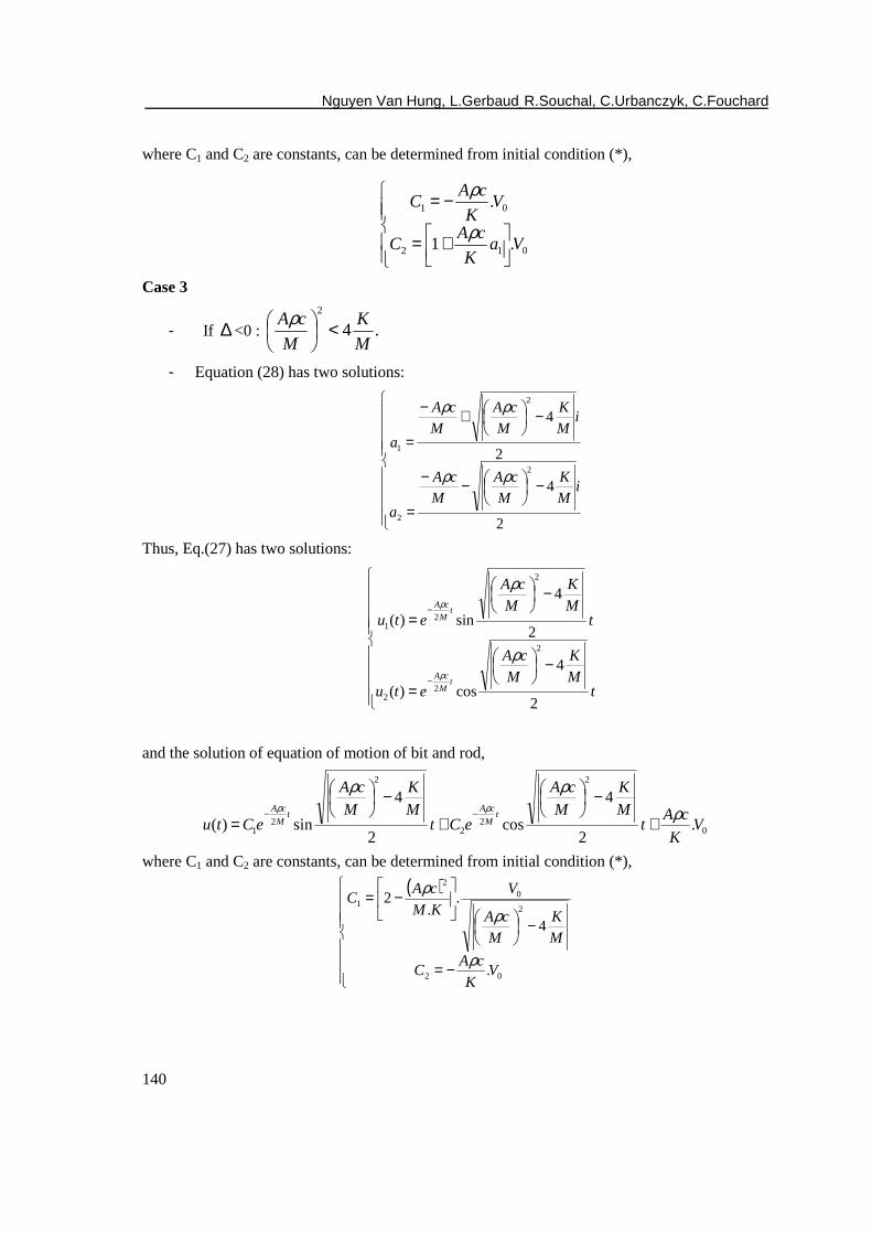
where C1 and C2 are constants, can be determined from initial condition (*),
+=
−=
012
01
.1
.
VaK
cAC
VK
cAC
ρ
ρ
Case 3
- If ∆ <0 : .42
M
K
M
cA <
ρ
- Equation (28) has two solutions:
−
−−
=
−
+−
=
2
4
2
4
2
2
2
1
iM
K
M
cA
M
cA
a
iM
K
M
cA
M
cA
a
ρρ
ρρ
Thus, Eq.(27) has two solutions:
−
=
−
=
−
−
tM
K
M
cA
etu
tM
K
M
cA
etu
tM
cA
tM
cA
2
4
cos)(
2
4
sin)(
2
22
2
21
ρ
ρ
ρ
ρ
and the solution of equation of motion of bit and rod,
0
2
22
2
21 .
2
4
cos2
4
sin)( VK
cAt
M
K
M
cA
eCtM
K
M
cA
eCtut
M
cAt
M
cA ρρρ
ρρ
+
−
+
−
=−−
where C1 and C2 are constants, can be determined from initial condition (*),
( )
−=
−
−=
02
2
02
1
.
4
..
2
VK
cAC
M
K
M
cA
V
KM
cAC
ρ
ρ
ρ
Penetration rate prediction for percussive drilling with rotary in very hard rock
141
Note: After [3], in the Fig. 4, when the hammer impacts the rod, a compressive stress wave iσ
is generated in the rod. The wave propagates towards the bit where it is denoted by iσ (t). At the
bit a reflected stress wave rσ is generated. At the rod-bit interface this wave is denoted by rσ (t). Under the combination action of the incident and reflected stress waves, the bit is accelerated
towards the rock, and work W is performed. When the reflected stress wave rσ arrives at the rod-hammer interface and the free end of the hammer, reflected stress waves are again generated. These waves form a second incident stress wave towards the bit which may or not cause further work to be done on the rock. From several points of view, for instance fatigue, it appears to be advantage to transfer a maximum of energy to the rock during the first stress wave interaction. From a series analysis of Lundberg, we found that more than 90% of the impact energy can be delivered to the rock during the first stress wave interaction, the effect of subsequent stress wave interactions has not be considered.
1.5. Limitation of stress wave theory
Stress wave theory is a mathematical model, from which the wave transmission is supposed to be along a slender bar with uniform section and mediums are full contact on the interface. We can derive from it that the full contact of bit front face with rock will result in the most efficient stress wave or impact energy transmission. However, this is completely contradictory with the fact that sharper bits drill faster or penetrate deeper and they have less contact area with rock surface in fact; example for a normal button bit, the practical contact area is about 10-20% of the bit front face area, and the sharper bits the less contact area [4].
2. NUMERICAL MODELING
In fact, during the past few years, with the rapid development of computing power, interactive computer graphics and topological data structure, a large number of numerical methods and fracture models have been developed for research on the rock fracture process during percussive drilling [5]. Bruno and Gang Han 2005 [6] used one numerical tools “Finite Element Modeling code FLAC3D” to investigate drillbit penetration with compression, rotation and percussion. Their model simulation indicates that compressive failure due to high impact force may be dominant rock failure during bit-rock contact, while rock may fail in tension if there is not enough bottom hole pressure acting on the exposed rock surface. Because rock tensile strength is usually 1/5 to 1/10 of rock compressive strength, it may fail more easily in tension if conditions permit. For instance, tensile failure can account for up to 90% of rock penetration when there is no pressure acting on top of the rock at the hole bottom. We can derive from it that to achieve the maximum drilling efficiency, encouraging rock deforming in tension is recommended.
Other interesting result is noted here that the optimum line spacing between the neighbouring button-bits has been proposed. This optimum line spacing is in fact a function of the drilled rock properties, the diameter and shape of the button-bit, as well as the drilling conditions:
aKEG
xF
xd
FS s
ICc
21
86853.2745434.22
23/2
2+
−
−= ν
σ
Nguyen Van Hung, L.Gerbaud, R.Souchal, C.Urbanczyk, C.Fouchard
142
where
• S is the optimum line spacing,
• F is the drilling force,
• Cσ is compressive strength,
• d is the size of the button-bit
• ν is Poisson’s ratio, Young’s modulus E,
• GIC is the energy release rate,
• Ks is coefficient of the button-bit shape (Ks=0 for the sharp button-bit, Ks=0.8 for the spherical button-bit, and Ks=1.0 for the blunt button-bit),
• a is radius of the contact area
3. RATE OF PENETRATION MODEL
Predicting and interpreting the rate of penetration (ROP) of a drill bit is very importance and help well planning and optimization drilling operation. Based on the current understanding, a rate of penetration model is proposed. In this part, we will present one analytical model of penetration rate, ROP, to operating condition rock strength and bit parameters.
3.1. Rock strength confinement
There are accepted methods in the literature to calculate rock confined compressive strength (TCS) based on rock unconfined compressive strength (UCS) and confinement pressure (Pc).
Φ−Φ++=
sin1
sin1cPUCSTCS (29)
)1( sbcsPaUCSTCS += (30)
Eq.(29) called Mohr-Coulomb strength criterion and Eq.(30) was proposed by [7].
where
• φ = Rock internal angle of friction,
• Pc = the pressure exerted on the rock matrix and is equal to difference of the applied external pressure (i.e. drilling mud dynamic or hydrostatic pressure) and the pore pressure of the fluid inside the rock.
• as and bs are coefficients dependent on rock
3.2. ROP model
We assume that the strain rates caused by a drill bit in percussive drilling are similar in the triaxial compression test. The confining pressure which is applied to the jacketed rock sample is interpreted as representing the bottom hole differential pressure in a wellbore. We should note
Penetration rate prediction for percussive drilling with rotary in very hard rock
143
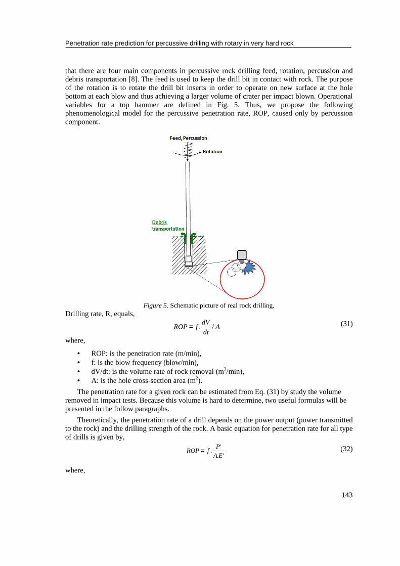
that there are four main components in percussive rock drilling feed, rotation, percussion and debris transportation [8]. The feed is used to keep the drill bit in contact with rock. The purpose of the rotation is to rotate the drill bit inserts in order to operate on new surface at the hole bottom at each blow and thus achieving a larger volume of crater per impact blown. Operational variables for a top hammer are defined in Fig. 5. Thus, we propose the following phenomenological model for the percussive penetration rate, ROP, caused only by percussion component.
Figure 5. Schematic picture of real rock drilling. Drilling rate, R, equals,
Adt
dVfROP /.= (31)
where,
• ROP: is the penetration rate (m/min), • f: is the blow frequency (blow/min), • dV/dt: is the volume rate of rock removal (m3/min), • A: is the hole cross-section area (m2).
The penetration rate for a given rock can be estimated from Eq. (31) by study the volume removed in impact tests. Because this volume is hard to determine, two useful formulas will be presented in the follow paragraphs.
Theoretically, the penetration rate of a drill depends on the power output (power transmitted to the rock) and the drilling strength of the rock. A basic equation for penetration rate for all type of drills is given by,
'.
'.
EA
PfROP= (32)
where,
Nguyen Van Hung, L.Gerbaud, R.Souchal, C.Urbanczyk, C.Fouchard
144
• ROP: is the penetration rate (m/min),
• f: is the blow frequency (blow/min),
• P': is the power transmitted to the rock,
• A: is the hole cross-section area (m2),
• E’: is the specific energy (N m/m3), or the energy required to remove a unit volume of rock,
An expression for the prediction of penetration rate derived by the senior author [9] is given below,
'.
..
EA
EfROP i η= (33)
where,
• ROP: is the penetration rate (m/min),
• f: is the blow frequency (blow/min),
• Ei: is the energy per blow (N m),
• η : is the efficiency of energy transmission from the drill bit to the rock,
• A: is the hole cross-section area (m2),
• E’: is the specific energy (N m/m3), or the energy required to remove a unit volume of rock.
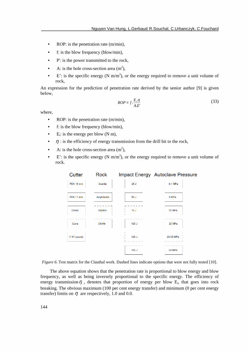
Figure 6. Test matrix for the Clauthal work. Dashed lines indicate options that were not fully tested [10].
The above equation shows that the penetration rate is proportional to blow energy and blow frequency, as well as being inversely proportional to the specific energy. The efficiency of energy transmissionη , denotes that proportion of energy per blow Ei, that goes into rock breaking. The obvious maximum (100 per cent energy transfer) and minimum (0 per cent energy transfer) limits on η are respectively, 1.0 and 0.0.
Penetration rate prediction for percussive drilling with rotary in very hard rock
145
It is well known from previously published works of [8] that specific energy in rock cutting is effected significantly by cutter geometry and rock properties. Ralf Luy 1992 [10] worked with 4 rocks (Granit, Amphibolit, Gabbro, Diorit) and five different cutters were used. The shapes and dimensions of these cutters and rocks properties are presented in the Fig.6 and Table 1.
Table 1. Compressive strength and densities of the rock specimens [10].
Rock type Compressive Strength, MPa Density, g/cm3
Granite 167 2,593
Diorite 180 2,959
Gabbro 281 2,620
Amphibolite 302 2,770
We can derived from his results that the specific energy, E’, is a function linear of bottom hole pressure, Eq.(34).
baPE b +=' (34)
where,
Ei: is the energy per blow (N m),
a,b: are the constants, depend on the rock properties and impact energy,
Pb: is the bottom hole pressure.
Substituting the Eq.(34) in Eq.(32), (33), the penetration rate can be determined by,
).(
'.
baPA
PfROP
b += (32bis)
Case 1
In practice, we can estimate rapid the penetration rate, ROP, by using the Eq.(33bis). The energy transmission efficiency, η , defined in [11, 12].
Case 2
In the general case, the penetration rate, ROP, determined by Eq.(32bis). The power transmitted to the rock, P’, equals the area under the curvature force F-displacement (Fig. 4). In the real case, the P’ value must be measured in dynamic test and P’ depends on impact velocity [2]. In the simplest case, we assume that the dynamic force-penetration curve is equivalent to the relationship between the stress-deformation in the triaxial test.
Nguyen Van Hung, L.Gerbaud, R.Souchal, C.Urbanczyk, C.Fouchard
146
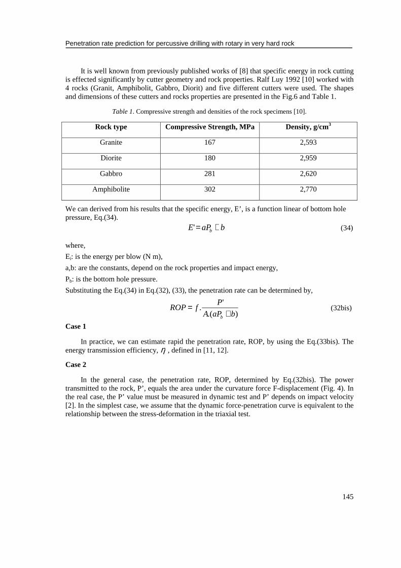
Figure 7. Idealized stress-deformation curve during percussive action ([3, 13]).
In the Fig. 7, we present the idealized stress, Pm-deformation, u curve during percussive action. Here, PM is the maximum mean stress, and uM is the maximum deformation, correspond to the rock sample is fracture. The power transmitted to the rock, P’, can calculated by,
)(2
1' MM uPP = (35)
The maximum mean stress is defined by,
3
2 bM
PTCSP
+= (36)
where,
TCS: is the triaxial compressive strength,
Pb: is the confining, corresponding to the bottom hole pressure.
From Eq.(29) in Eq.(36), we have:
bM PUCS
P .sin1
sin3
3 Φ−Φ−+= (37)
Substituting Eq.(35) and Eq.(37) in to Eq.(32bis), the formula of penetration rate becomes,
mb
b
ubaPA
PUCS
fROP .)(2
sin1
sin3
3.+
Φ−Φ−+
= (38)
Our model proposed Eq. (38) shows that the penetration rate, ROP, relates to rock properties and drilling conditions. Yet, the bottom hole pressure has been account in to our model.
4. EXPERIMENTAL MODEL
In the previous paper [1], the experimental model has established following relationship:
ROP=-0.0283UCS + 15.11, with R2=0.5632
ROP = -0.0198TCS + 15.387, with R2=0.6635
Penetration rate prediction for percussive drilling with rotary in very hard rock
147
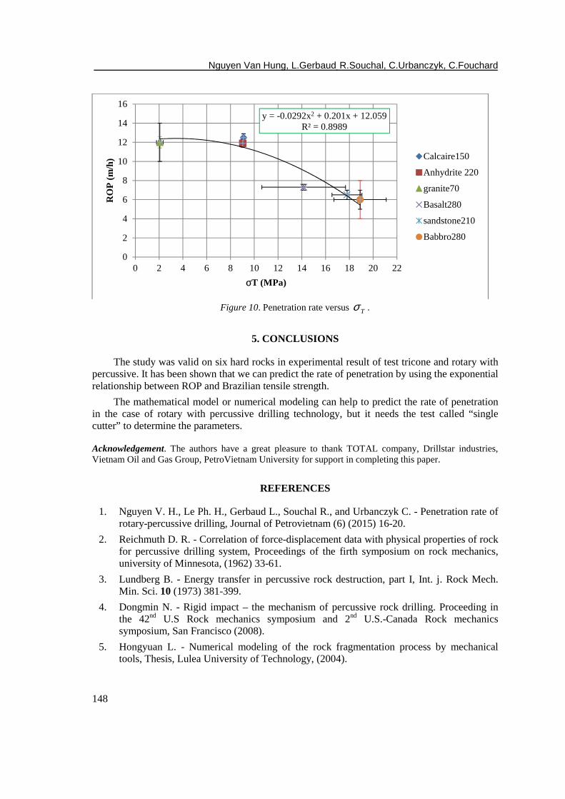
ROP = -0.4316 Tσ + 14.478, with R2=0.8001
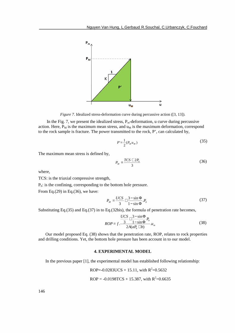
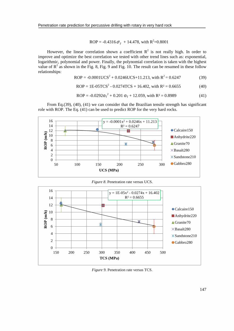
However, the linear correlation shown a coefficient R2 is not really high. In order to improve and optimize the best correlation we tested with other trend lines such as: exponential, logarithmic, polynomial and power. Finally, the polynomial correlation is taken with the highest value of R2 as shown in the Fig. 8, Fig. 9 and Fig. 10. The result can be resumed in these follow relationships:
ROP = -0.0001UCS2 + 0.0246UCS+11.213, with R2 = 0.6247 (39)
ROP = 1E-05TCS2 - 0.0274TCS + 16.402, with R² = 0.6655 (40)
ROP = -0.0292σT2 + 0.201 σT + 12.059, with R² = 0.8989 (41)
From Eq.(39), (40), (41) we can consider that the Brazilian tensile strength has significant role with ROP. The Eq. (41) can be used to predict ROP for the very hard rocks.
Figure 8. Penetration rate versus UCS.
Figure 9. Penetration rate versus TCS.
y = -0.0001x2 + 0.0246x + 11.213R² = 0.6247
02468
10121416
50 100 150 200 250 300
RO
P (
m/h
)
UCS (MPa)
Calcaire150
Anhydrite220
Granite70
Basalt280
Sandstone210
Gabbro280
y = 1E-05x2 - 0.0274x + 16.402R² = 0.6655
0
2
4
6
8
10
12
14
16
150 200 250 300 350 400 450 500
RO
P (
m/h
)
TCS (MPa)
Calcaire150
Anhydrite220
Granite70
Basalt280
Sandstone210
Gabbro280
Nguyen Van Hung, L.Gerbaud, R.Souchal, C.Urbanczyk, C.Fouchard
148
Figure 10. Penetration rate versus Tσ .
5. CONCLUSIONS
The study was valid on six hard rocks in experimental result of test tricone and rotary with percussive. It has been shown that we can predict the rate of penetration by using the exponential relationship between ROP and Brazilian tensile strength.
The mathematical model or numerical modeling can help to predict the rate of penetration in the case of rotary with percussive drilling technology, but it needs the test called “single cutter” to determine the parameters.
Acknowledgement. The authors have a great pleasure to thank TOTAL company, Drillstar industries, Vietnam Oil and Gas Group, PetroVietnam University for support in completing this paper.
REFERENCES
1. Nguyen V. H., Le Ph. H., Gerbaud L., Souchal R., and Urbanczyk C. - Penetration rate of rotary-percussive drilling, Journal of Petrovietnam (6) (2015) 16-20.
2. Reichmuth D. R. - Correlation of force-displacement data with physical properties of rock for percussive drilling system, Proceedings of the firth symposium on rock mechanics, university of Minnesota, (1962) 33-61.
3. Lundberg B. - Energy transfer in percussive rock destruction, part I, Int. j. Rock Mech. Min. Sci. 10 (1973) 381-399.
4. Dongmin N. - Rigid impact – the mechanism of percussive rock drilling. Proceeding in the 42nd U.S Rock mechanics symposium and 2nd U.S.-Canada Rock mechanics symposium, San Francisco (2008).
5. Hongyuan L. - Numerical modeling of the rock fragmentation process by mechanical tools, Thesis, Lulea University of Technology, (2004).
y = -0.0292x2 + 0.201x + 12.059R² = 0.8989
0
2
4
6
8
10
12
14
16
0 2 4 6 8 10 12 14 16 18 20 22
RO
P (
m/h
)
σT (MPa)
Calcaire150
Anhydrite 220
granite70
Basalt280
sandstone210
Babbro280
Penetration rate prediction for percussive drilling with rotary in very hard rock
149
6. Bruno M. - Fundamental research on percussion drilling: Improved rock mechanics analysis, advanced simulation technology, and full scale laboratory investigations. DE-FC26-03NT41999. Final report, DOE, (2005).
7. Rampersad P., Hareland G., and Boonyapaluk P. - Drilling optimization using drilling data and available technology. SPE 27034, SPE Latin America/Caribblean Petroleum Engineering Conference, 27-29 April, Buenos Aires, Argentina, 1994.
8. Kahraman S., Bilgin N., and Feridunoglu C. - Dominant rock properties affecting the penetration rate of percussive drills, Int. j. Rock Mech. Min. Sci. 40 (2003) 711-723.
9. Hustrulid W. A. - A study of energy transfer to rock and prediction of drilling rates in percussive drilling, M.S. Thesis, University of Minnesota, (1965).
10. Ralf Luy. - Untersuchung zur Wirksamkeit des bohrprozesses beim drehschlagenden bohren unter hohen hydrostatischen drucken. Thesis at Technischen Universitat Clausthal (in Germany), (1992).
11. Li X. B., Rupert G., and Summers D. A. - Energy transmission of down-hole hammer tool and its coditionality, Trans. Nonferrous Met. Soc. China 1 (10) (2000) 110-113.
12. Li X. B., Lok T. S., Summers D.A., Rupert G., and Tyler J. - Stress and energy reflection from impact on rock using different indentors, Geotech.Geolog. Engineering 19 (2001) 119-136.
13. Lundberg B., and Collet P. - Optimal wave with respect to efficiency in percussive drilling with integral drill steel, Int. J. Impact Eng. 8 (37) (2010) 901-906.
TÓM TẮT
DỰ BÁO TỐC ĐỘ KHOAN CƠ HỌC ĐỐI VỚI CÔNG NGHỆ KHOAN ĐẬP KẾT HỢP XOAY TRONG TRƯỜNG HỢP KHOAN ĐÁ RẤT CỨNG
Nguyen Van Hung1, *, L. Gerbaud2, R. Souchal3, C. Urbanczyk4, C. Fouchard4
1Đại học Dầu khí, đường Cách Mạng Tháng 8, Tỉnh Bà Rịa – Vũng Tàu, Việt Nam
2Ecole des Mines ParisTech, 60 Boulevard Saint-Michel, 75006 Paris, France 3Drillstar industries, Avenue Frédéric et Irène Joliot Curie, 64140 Lons, France
4Total, Avenue Larribau, 64000 Pau, France
*Email: [email protected]
Bài báo này là phần tiếp theo trong dự án xây dựng và dự báo tốc độ khoan cơ học của công nghệ khoan đập kết hợp xoay trong dầu khí đối với trường hợp đá rất cứng. Như kết quả đã chỉ ra trong [1] mô hình dự báo tốc độ khoan phụ thuộc nhiều vào độ bền kéo Brazilian và đồng thời cũng tồn tại mối liên hệ giữa tốc độ khoan và tính chất của đá. Ngoài ra, nghiên cứu đã dựa trên kết quả thực nghiệm của sáu loại đá cứng trên cơ sở thí nghiệm choòng ba chóp xoay và thí nghiệm khoan đập kết hợp xoay. Tất cả mối liên hệ chỉ ra mối liên hệ nhưng hệ số R2 khá nhỏ. Bài báo này sẽ giới thiệu mối liên hệ mới với hệ số R2 cao hơn dựa trên cơ sở kết quả thí nghiệm trước kia và đồng thời cũng giới thiệu mô hình toán học, mô hình số để dự báo tốc độ khoan.
Từ khóa: đá cứng, ROP, khoan, mô hình toán học, mô hình số.