pellet boiler biodom 33 - biodombaltia.com · pellet boiler biodom 33 instructions for use,...
TRANSCRIPT

__________
PELLET BOILER
BIODOM 33
Instructions for use, maintenance and installation
__________
Version 1.0 / July 2017
Biodom 33 | instructions for use, maintenance and installation | version 1.0 July 2017
2
We thank you for your purchase of Biodom boiler. We ask to thoroughly read instructions for use
before installing and using your pellet boiler Biodom. Heating appliances (in the following: "pellet
boiler" or "boiler") of company Biodom 27 d.o.o. (in the following: Biodom) are manufactured and
tested in accordance with safety requirements of European Directives in force.
These instructions are intended for end users, installers and authorized maintenance personnel for
Biodom pellet boilers. If you have any doubts regarding the instructions for use or require any
clarification, please contact the manufacturer or authorized person of company Biodom 27 d.o.o.
directly.
Printing, translation or reproduction, even in part, of the instructions of use is possible only upon
approval by company Biodom 27 d.o.o..
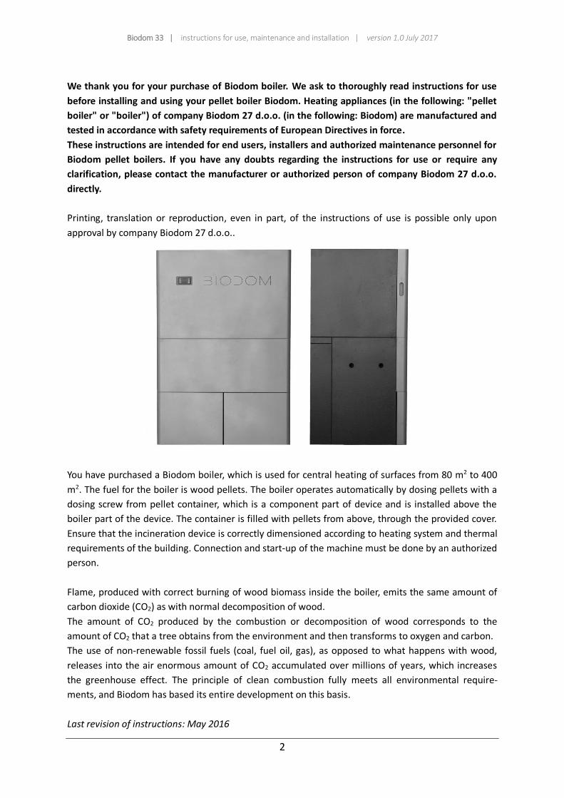
You have purchased a Biodom boiler, which is used for central heating of surfaces from 80 m2 to 400
m2. The fuel for the boiler is wood pellets. The boiler operates automatically by dosing pellets with a
dosing screw from pellet container, which is a component part of device and is installed above the
boiler part of the device. The container is filled with pellets from above, through the provided cover.
Ensure that the incineration device is correctly dimensioned according to heating system and thermal
requirements of the building. Connection and start-up of the machine must be done by an authorized
person.
Flame, produced with correct burning of wood biomass inside the boiler, emits the same amount of
carbon dioxide (CO2) as with normal decomposition of wood.
The amount of CO2 produced by the combustion or decomposition of wood corresponds to the
amount of CO2 that a tree obtains from the environment and then transforms to oxygen and carbon.
The use of non-renewable fossil fuels (coal, fuel oil, gas), as opposed to what happens with wood,
releases into the air enormous amount of CO2 accumulated over millions of years, which increases
the greenhouse effect. The principle of clean combustion fully meets all environmental require-
ments, and Biodom has based its entire development on this basis.
Last revision of instructions: May 2016
Biodom 33 | instructions for use, maintenance and installation | version 1.0 July 2017
3
INDEX
1. PURPOSE OF INSTRUCTIONS FOR USE ...........................................................................................5
1.1. UPDATES ..............................................................................................................................5
2. RESPONSIBILITY OF MANUFACTURER............................................................................................5
2.1. BASIC PREVENTIVELY REQUIRED STANDARDS .......................................................................5
2.2. TRANSPORTATION AND HANDLING OF PELLET BOILER .........................................................6
2.3. RESPONSIBILITY OF INSTALLER .............................................................................................6
3. INSTALLATION ................................................................................................................................7
3.1. PLACEMENT .........................................................................................................................7
3.2. EXTRACTION OF SMOKE GASES .......................................................................................... 10
3.3. INSULATION AND DIAMETER OF HOLES IN THE ROOF ........................................................ 12
3.4. INLET AIR ........................................................................................................................... 12
3.5. ELECTRICAL CONNECTION .................................................................................................. 13
4. BOILER COMMISSIONING ............................................................................................................ 14
5. SAFETY WARNINGS...................................................................................................................... 15
5.1. SAFETY WARNINGS FOR MAINTENANCE STAFF .................................................................. 15
5.2. SAFETY WARNINGS FOR USER ............................................................................................ 15
6. INSTRUCTIONS FOR SAFE IGNITION AND CLEANING OF BOILER .................................................. 17
6.1. REGULAR MAINTENANCE AND CLEANING OF BOILER ......................................................... 17
6.2. CONTROL AND PARTS REQUIRING MAINTENANCE ............................................................. 19
6.3. ADDITIONAL MAINTENANCE .............................................................................................. 20
7. IMPORTANT SAFETY INFORMATION ............................................................................................ 20
8. PELLET QUALITY IS VERY IMPORTANT ......................................................................................... 20
8.1. STORING PELLETS .............................................................................................................. 21
9. DESCRIPTION AND OPERATION OF CONTROL DEVICE.................................................................. 22
9.1. BOILER DURING OPERATION .............................................................................................. 26
9.2. BOILER SHUTDOWN ........................................................................................................... 26
9.3. BOILER ACTIVATION ........................................................................................................... 26
9.4. TIME PROGRAMME SETTING ............................................................................................. 27
9.5. INDICATIONS AND MESSAGES ON DISPLAY ......................................................................... 29
10.MENU .......................................................................................................................................... 31
11.ALARM STATUSES ........................................................................................................................ 33
Biodom 33 | instructions for use, maintenance and installation | version 1.0 July 2017
4
12.INFORMATION REGARDING DESTRUCTION AND DISPOSAL OF BOILER ....................................... 40
13.WARRANTY CONDITIONS ............................................................................................................ 41
14.TECHNICAL CHARACTERISTICS OF MODEL BIODOM 33 ............................................................... 44
15.DIMENSIONS OF BOILER BIODOM 33 .......................................................................................... 45
16.INSTRUCTIONS FOR INSTALLERS .................................................................................................. 46
17.BOILER CONNECTION INSTRUCTIONS .......................................................................................... 47
18.CONNECTION SCHEMES ............................................................................................................... 50
18.1. SCHEME NR.1: SYSTEM WITH RADIATOR THERMOSTAT VALVES .......................................... 50
18.2. SCHEME NR.2: SYSTEM WITH RADIATOR THERMOSTAT VALVES AND WITH BOILER............. 52
18.3. SCHEME NR.3: HEATING WITH MULTIPLE SYSTEMS ............................................................ 54
19.INSTRUCTIONS FOR FIRST START-UP ........................................................................................... 56
20.DECLARATION OF CONFORMITY .................................................................................................. 59
Biodom 33 | instructions for use, maintenance and installation | version 1.0 July 2017
5
1. PURPOSE OF INSTRUCTIONS FOR USE
The purpose of instructions for use is that the user takes all necessary measures and prepares all
required equipment to ensure safe and proper use of combustion device.
1.1. UPDATES
These instructions reflect the state of the product at the moment the boiler is produced.
Instructions are not applicable for products, which are already present on the market with corre-
sponding technical documentation and cannot be considered as insufficient or inadequate after any
modification, adaptation or application of new technologies on newer products.
The content of this booklet must be carefully read and heeded to. All of the information, contained in
this booklet, is necessary for correct installation, use and maintenance of you boiler.
The instructions must be stored carefully and safely. Instructions for use, maintenance and
installation are a component part of pellet boiler.
If the pellet boiler changes ownership to another person, this person must also receive these
instructions for use, together with the boiler.
If the instructions get lost, request for a new copy of instructions from the manufacturer, authorized
reseller or repairman.
2. RESPONSIBILITY OF MANUFACTURER
In providing these instructions, Biodom 27 d.o.o. rejects any civil or penal liability, direct or indirect, due to:
accidents caused by non-compliance with standards and specifications from these instructions;
accidents caused by prohibited or incorrect use by the user;
accidents caused by modifications and repairs not authorized by manufacturer Biodom 27 d.o.o.;
poor maintenance;
unforeseeable events;
accidents caused by use of non-original or improper spare parts.
The installer is fully responsible for installation.
2.1. BASIC PREVENTIVELY REQUIRED STANDARDS
Product Biodom 27 E is manufactured in accordance with the following standards:
DIRECTIVE EC ON MACHINERY (2006/42/EC); DIRECTIVE EC ON LOW-VOLTAGE EQUIPMENT (2014/35/ES); DIRECTIVE EC ON ELECTROMAGNETIC COMPATIBILITY (2014/30/ES); DIRECTIVE EC ON BOILERS FOR HEATING ON SOLID FUELS UP TO NOMINAL POWER kW; EN 303-5
Biodom 33 | instructions for use, maintenance and installation | version 1.0 July 2017
6
Harmonized standards:
SIST EN ISO 12100-1: 2004 and A1: 2010;
SIST EN ISO 12100-2: 2004 and A1: 2010;
SIST EN 303-5: 2012;
61000-6-3: 2007;
61000-6-2: 2005;
61000-3-3: A1 2002;
61000-3-3: A2 2006;
EN 60204-1: 2006 and A1:2009.
2.2. TRANSPORTATION AND HANDLING OF PELLET BOILER
When moving the boiler, pay attention to your safety.
Before transport and handling of the boiler, which must be performed in complete safety, make sure
that the lifting capacity of transport equipment suffices. Avoid sudden and/or abrupt movement of
boiler.
ATTENTION
DISCARD ALL PACKAGING OUT OF REACH OF CHILDREN. DANGER OF SUFFOCATION WITH
BAG, FOIL, POLYSTYRENE ETC.
2.3. RESPONSIBILITY OF INSTALLER
It is the responsibility of the installer to check adequacy of installation and pipeline, ensure air intake
for combustion, ensures regulated distances and all other solutions, required for installation of the
pellet boiler.
It is the responsibility of the installer to ensure compliance with local legislation in force in the place
of pellet boiler installation.
Use of the pellet boiler must conform with instructions, provided in Instructions for use, maintenance
and installation, and all safety standards, specified by local legislation in the place of pellet boiler
installation.
Standard UNI 10683 defines duties of installer. The installer must check:
type of device to be installed;
adequacy of space for installation of unit, reflected by minimum required size of the space, in which the pellet boiler will be installed;
instructions of the manufacturer about heating device, regarding requirements of smoke
gases outlet;
flue pipe internal diameter, the material it is made of, is it straight or even and that there are
no obstructions;
height and, if required, vertical extension of flue pipe;
Biodom 33 | instructions for use, maintenance and installation | version 1.0 July 2017
7
existence and suitability of flue pipe cover resistance;
possibility of outside air intake;
possibility of simultaneous use of generator for connection with other equipment.
If the results of all above provided checks are positive, installation may proceed. Carefully heed to
instructions provided by the manufacturer, as well as safety and fire prevention standards in force.
After the first start-up of the boiler, perform a minimum 30-minute test of operation to check all
required demands.
When the installation is complete, the installer must provide the customer with the following:
instructions for use, maintenance and installation from the manufacturer (if not included in
the unit);
required documentation in accordance with standards in force;
perform training of customer for operation and regular maintenance and cleaning of the
device.
3. INSTALLATION
Responsibility for installation work in the space is entirely upon the customer.
Before proceeding with installation, the installer must comply with all required legal safety standards,
especially:
Check that norms regarding pellet boiler installation meet local, national and European
norms
Heed to requirements set forth in this document
Check that pipes and air intake are compliant with the type of installation
Do not make temporary electrical connections by using unsuitable cables
Check earthing of electrical system
Always use individual safety equipment and all legally required protection
Always allow sufficient space for maintenance work
Acquire consent of chimney sweep for connection of boiler to flue
Perform measurement of smoke gases outlet after finished installation.
3.1. PLACEMENT
It is advisable to remove pellet boiler packaging only when it is in the place of installation.
If the adjacent walls and/or flooring are made of material that is not heat resistant, suitable
protection must be provided using insulating, non-combustible material.
For protection of flooring, made of flammable material, we advise installing a metal plate with
thickness 3 to 4 mm under the boiler, which protrudes at least 30 cm out from the front of the pellet
boiler.
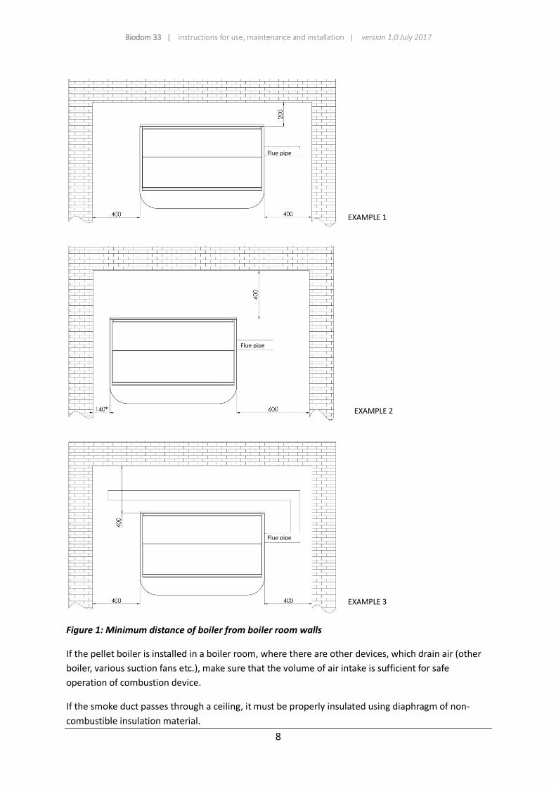
Pellet boiler must be installed in accordance with drawing that defines distances from walls (figure 1).
Biodom 33 | instructions for use, maintenance and installation | version 1.0 July 2017
8
Figure 1: Minimum distance of boiler from boiler room walls
If the pellet boiler is installed in a boiler room, where there are other devices, which drain air (other
boiler, various suction fans etc.), make sure that the volume of air intake is sufficient for safe
operation of combustion device.
If the smoke duct passes through a ceiling, it must be properly insulated using diaphragm of non-
combustible insulation material.
Flue pipe
EXAMPLE 1
EXAMPLE 2
Flue pipe
Flue pipe
EXAMPLE 3
Biodom 33 | instructions for use, maintenance and installation | version 1.0 July 2017
9
When the pellet boiler is placed, it must be levelled with support feet (horizontal positioning).
ATTENTION
Smoke gas discharge MUST NOT BE CONNECTED TO:
Flue pipe, used by other combustion devices (boilers, stoves, fireplaces etc.);
Air extraction systems (hoods, air extraction fans etc.).
ATTENTION
Installation of draught closing valves is prohibited! Flue connection Ø 80 mm from pellet boiler to flue pipe should be:
no more than 5 m long (in case of longer connection, dimension of connection pipe must increase to Ø 130 mm);
each 90° joint requires a 1 m shorter flue connection;
each joint must be fitted with doors for cleaning;
connections between pipes must be sealed.
ATTENTION
If there is too much resistance in extraction system (many joints, improper end fitting, bottlenecks etc.), extraction of smoke gases is not provided for. Therefore, connection pipes and joints must be increased to a greater dimension – Ø 130 mm. If the flue does not ensure appropriate extraction of smoke gases, it can also come do improper operation and, consequently, to alarm from boiler Biodom 33. It is advisable that the flue is inspected by an expert before installing boiler Biodom 33.
Smoke gases extraction system from pellet boiler functions on the basis of negative pressure in the
boiler and barely perceivable pressure in flue connection pipe Ø 80 mm. It is very important that the
smoke gases extraction is sealed.
Layout and structure of the space, where the flue is installed, needs to be analyzed. If it passes
through walls and/or roof, it must be properly installed in accordance with fire prevention safety
standards.
Ensure that there is enough air for proper combustion in the space, where the pellet boiler is
installed. If boiler Biodom 33 lacks oxygen/air, the boiler displays an alarm. External supply or intake
of external air requires a pipe with a diameter of at least 110 mm with maximum length of 10 m. Each
90° joint requires a deduction of 1 m in line length. If the air supply is longer, diameter of air intake
pipe must be increased.
In case of a grid on the facade, draught opening must be 100 cm² or larger.
Biodom 33 | instructions for use, maintenance and installation | version 1.0 July 2017
10
The device operates at 220 V – 50 Hz. Make sure that the electrical cables are not laid under the
boiler, that they are far away from hot surfaces and that they do not touch sharp parts, which could
damage them. If the pellet boiler is under electrical overload, life expectancy of electrical component
greatly reduces.
ATTENTION
Never turn off the boiler by pulling the electrical cable from the socket, while fire is still
burning in the boiler. This could damage the boiler and seriously jeopardize its functioning.
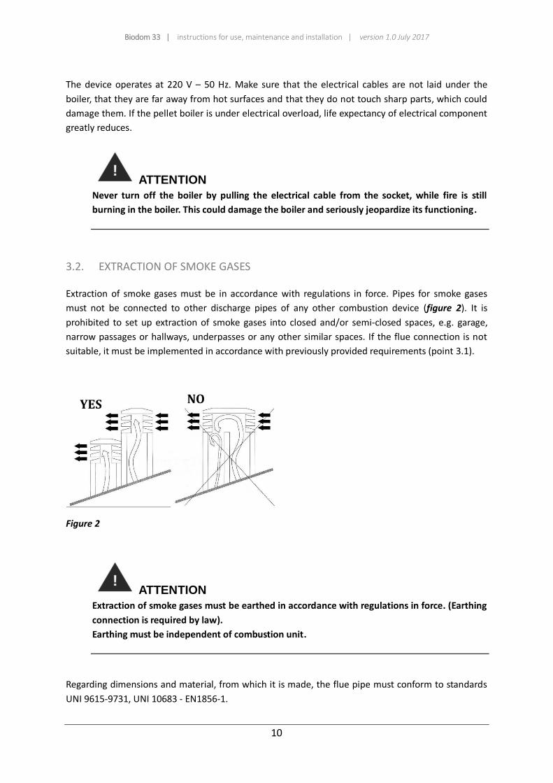
3.2. EXTRACTION OF SMOKE GASES
Extraction of smoke gases must be in accordance with regulations in force. Pipes for smoke gases
must not be connected to other discharge pipes of any other combustion device (figure 2). It is
prohibited to set up extraction of smoke gases into closed and/or semi-closed spaces, e.g. garage,
narrow passages or hallways, underpasses or any other similar spaces. If the flue connection is not
suitable, it must be implemented in accordance with previously provided requirements (point 3.1).
Figure 2
ATTENTION
Extraction of smoke gases must be earthed in accordance with regulations in force. (Earthing
connection is required by law).
Earthing must be independent of combustion unit.
Regarding dimensions and material, from which it is made, the flue pipe must conform to standards
UNI 9615-9731, UNI 10683 - EN1856-1.
YES NO
Biodom 33 | instructions for use, maintenance and installation | version 1.0 July 2017
11
Flue pipes in poor condition and/or made of unsuitable materials (asbestos, zinced sheet metal etc.,
with rough or porous surfaces) are prohibited by law and compromise proper boiler operation.
Smoke can be extracted through a traditional flue pipe (see figure below) provided that the following
rules are met:
Check condition of flue pipe maintenance. For proper maintenance and/or restoration
contact chimney sweep service.
Extraction of smoke gases can be connected directly to flue pipe only if it has a maximum
dimension of 20 x 20 cm or diameter of 20 cm and is fitted with inspection hole.
If the flue pipe is of greater dimensions, a stainless pipe (with required diameter) with proper
insulation must be installed into it.
Make sure that the connection with the flue pipe is properly sealed.
Avoid contact with flammable material (such as wood ashes), and, in any case, insulate them
with fire-resistant material.
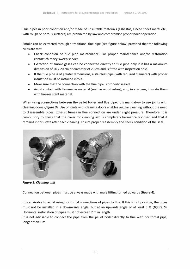
When using connections between the pellet boiler and flue pipe, it is mandatory to use joints with
cleaning doors (figure 3). Use of joints with cleaning doors enables regular cleaning without the need
to disassemble pipes. Exhaust fumes in flue connection are under slight pressure. Therefore, it is
compulsory to check that the cover for cleaning ash is completely hermetically closed and that it
remains in this state after each cleaning. Ensure proper reassembly and check condition of the seal.
Figure 3: Cleaning unit
Connection between pipes must be always made with male fitting turned upwards (figure 4).
It is advisable to avoid using horizontal connections of pipes to flue. If this is not possible, the pipes
must not be installed in a downwards angle, but at an upwards angle of at least 5 % (figure 5).
Horizontal installation of pipes must not exceed 2 m in length.
It is not advisable to connect the pipe from the pellet boiler directly to flue with horizontal pipe,
longer than 1 m.

Biodom 33 | instructions for use, maintenance and installation | version 1.0 July 2017
12
Figure 4 Figure 5
3.3. INSULATION AND DIAMETER OF HOLES IN THE ROOF
Once the position of boiler installation is determined, a hole for passage of smoke pipes must be
made. This changes in regard to the type of installation, diameter of smoke pipes and type of wall or
roof, through which it must be guided. Insulation must be of mineral origin (rock wool) with nominal
density greater than 80 kg/m³.
Perfect draught depends mostly on flue pipe, which must be free of obstructions, such as bottlenecks
and/or various joint connections. Joint must be at an angle of 30°, 45° and 90°. Joints at an angle of
90° must be made of three parts (figure 6).
In any case, it is mandatory to provide an initial vertical straight pipe of 1,5 metres in length
(minimum) to ensure correct extraction of smoke gases.
Figure 6
3.4. INLET AIR
Air from the environment, required for correct combustion, must be refreshed with new air, through
opening in the wall, slot in boiler room doors or grid on the window. This will ensure proper
combustion and proper boiler operation.
Opening for intake of fresh air must also be fitted with protective slot against rain, wind and insects.
Hole must be made on the external wall of the space, where the pellet boiler is installed.
Standard UNI 10683 prohibits intake of inlet air from storage of flammable materials or spaces with
the risk of fire.
5 % or more
Biodom 33 | instructions for use, maintenance and installation | version 1.0 July 2017
13
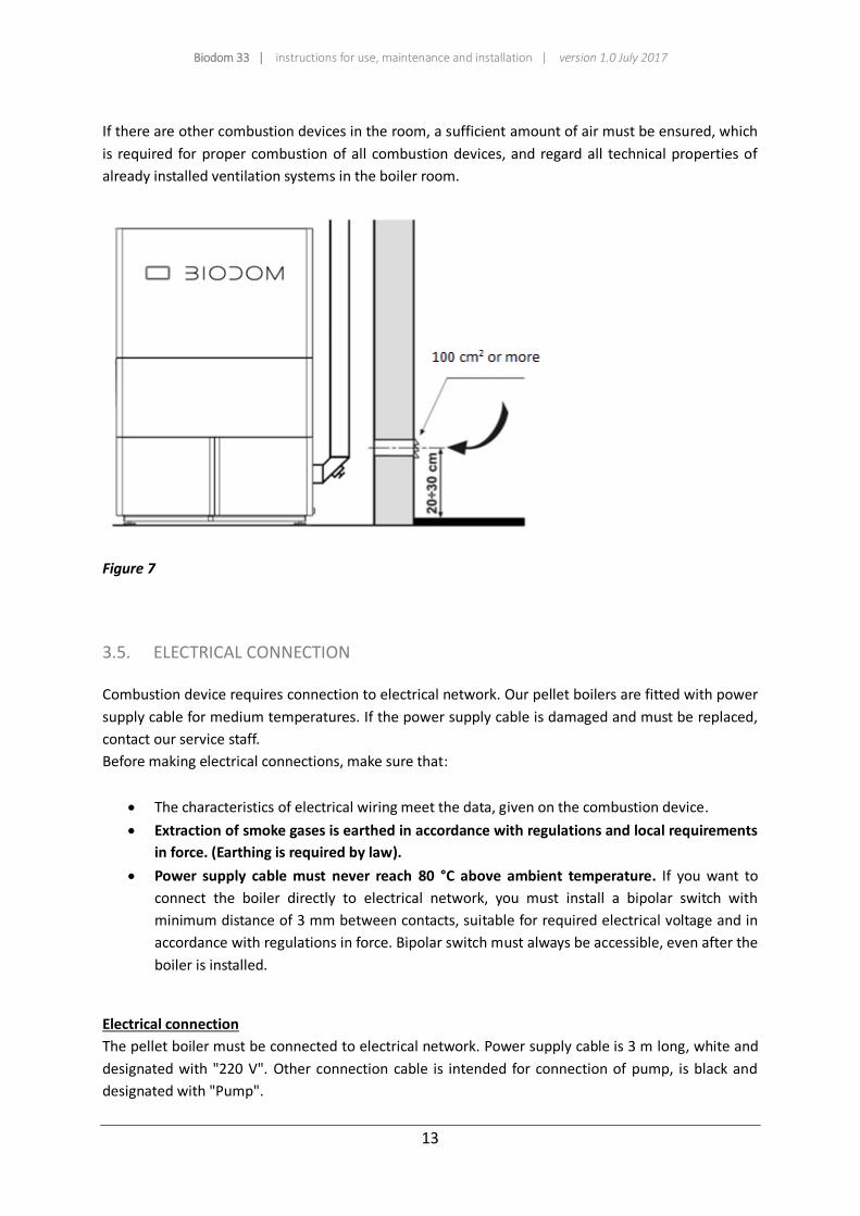
If there are other combustion devices in the room, a sufficient amount of air must be ensured, which
is required for proper combustion of all combustion devices, and regard all technical properties of
already installed ventilation systems in the boiler room.
Figure 7
3.5. ELECTRICAL CONNECTION
Combustion device requires connection to electrical network. Our pellet boilers are fitted with power
supply cable for medium temperatures. If the power supply cable is damaged and must be replaced,
contact our service staff.
Before making electrical connections, make sure that:
The characteristics of electrical wiring meet the data, given on the combustion device.
Extraction of smoke gases is earthed in accordance with regulations and local requirements
in force. (Earthing is required by law).
Power supply cable must never reach 80 °C above ambient temperature. If you want to
connect the boiler directly to electrical network, you must install a bipolar switch with
minimum distance of 3 mm between contacts, suitable for required electrical voltage and in
accordance with regulations in force. Bipolar switch must always be accessible, even after the
boiler is installed.
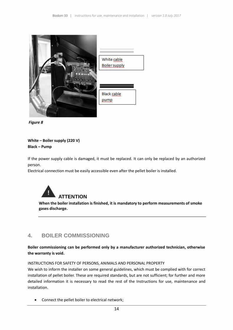
Electrical connection
The pellet boiler must be connected to electrical network. Power supply cable is 3 m long, white and
designated with "220 V". Other connection cable is intended for connection of pump, is black and
designated with "Pump".
Biodom 33 | instructions for use, maintenance and installation | version 1.0 July 2017
14
Figure 8
White – Boiler supply (220 V)
Black – Pump
If the power supply cable is damaged, it must be replaced. It can only be replaced by an authorized
person.
Electrical connection must be easily accessible even after the pellet boiler is installed.
ATTENTION
When the boiler installation is finished, it is mandatory to perform measurements of smoke gases discharge.
4. BOILER COMMISSIONING
Boiler commissioning can be performed only by a manufacturer authorized technician, otherwise
the warranty is void.
INSTRUCTIONS FOR SAFETY OF PERSONS, ANIMALS AND PERSONAL PROPERTY
We wish to inform the installer on some general guidelines, which must be complied with for correct
installation of pellet boiler. These are required standards, but are not sufficient; for further and more
detailed information it is necessary to read the rest of the Instructions for use, maintenance and
installation.
Connect the pellet boiler to electrical network;
Biodom 33 | instructions for use, maintenance and installation | version 1.0 July 2017
15
Do not allow children or animals in the boiler area;
Use only quality pellets and no other types of fuel;
Inform all users on possible risks and hazards, and educate them on handling the pellet
boiler;
If the pellet boiler is placed on a wooden floor, it is advisable to protect the floor in
accordance with regulations.
ATTENTION
The pellet boiler operates by creating negative pressure in the combustion chamber.
Therefore, ensure that the extraction of smoke gases is thermally sealed.
Upon first start-up (minimum operation of boiler – 1 hour), paint evaporates fumes, which
have unpleasant odour. Therefore, ventilate the room afterwards.
5. SAFETY WARNINGS
5.1. SAFETY WARNINGS FOR MAINTENANCE STAFF
Along with adhering to general safety regulations, maintenance staff must also:
Always use safety devices and individual safety equipment according to Directive
89/391/EEC;
Disconnect power supply before commencing any work;
Always use suitable tools;
Before commencing any work on the boiler, ensure that the boiler, as well as the ashes in it,
are cold, especially before touching it;
PELLET BOILER IS NOT TO BE CONSIDERED USABLE, IF EVEN ONE SAFETY DEVICE IS
MALFUNCTIONING, INCORRECTLY REPAIRED OR NOT FUNCTIONING!
Do not perform any modifications of any type for whatever reason other than those allowed
and/or approved by the manufacturer or authorized person.
Always use original spare parts. Do not wait for boiler components to wear out before
replacing them. Replacing a worn-out part, before it malfunctions, helps prevent injuries,
caused by sudden failure of a component, which can seriously jeopardize persons and/or
their property.
When cleaning ash, also clean the combustion container and space beneath it.
5.2. SAFETY WARNINGS FOR USER
Space, where the pellet boiler will be placed, or installation area, must be in accordance with local,
national and European directives.

Biodom 33 | instructions for use, maintenance and installation | version 1.0 July 2017
16
The pellet boiler is a combustion device and external surfaces of the boiler can reach higher
temperatures during operation.
The pellet boiler is a C1 class boiler, produced exclusively for burning wood pellets (pellets of 6 mm in
diameter and 30 mm in length with maximum moisture content up to 10 %) or for fuel C1 (wood
pellets) in accordance with standard EN 14961-2.
ATTENTION
DURING PELLET BOILER OPERATION, CHILDREN ARE PROHIBITED TO COME NEAR OR PLAY
WITH IT!
When using a combustion device, it is advisable to take special care of the following:
during boiler operation DO NOT approach it and do not touch the doors of combustion
chamber, because of DANGER OF BURNS
during boiler operation DO NOT approach it and do not touch the flue connection, because of
DANGER OF BURNS
during boiler operation DO NOT perform any kind of cleaning on the combustion device
during boiler operation do not open the doors of the firebox, because it operates properly
only when its doors are hermetically sealed (if you open the doors during operation, an alarm
will sound)
during boiler operation DO NOT remove ashes
DO NOT allow children and animals to come near the pellet boiler
ADHERE TO REQUIREMENTS SET FORTH IN THIS DOCUMENT
For correct use of the boiler, also heed to the following instructions:
Use only and exclusively fuel recommended by boiler manufacturer;
Follow instructions for maintenance;
Clean the boiler firebox for each pellet container used (3-14 days, when the pellet boiler and
ashes in it are cool);
DO NOT use the pellet boiler in case of operation malfunction or other irregularities,
abnormal noises and/or suspicious faults and IMMEDIATELY contact authorized service
personnel;
DO NOT spill water on the boiler, as well as put out fire in the combustion chamber with
water;
DO NOT lean on the boiler, as it may be unstable and could tip over;
DO NOT use the pellet boiler as support or a fastening item. Do not leave the container cover
open;
DO NOT touch the painted surfaces of the boiler during operation;
DO NOT use wood or charcoal in the pellet boiler, use only pellets with the following
properties:
dimension: diameter 6 mm,
Biodom 33 | instructions for use, maintenance and installation | version 1.0 July 2017
17
maximum length: 30 mm,
moisture content: up to 10 %,
combustion value: minimum 16,9 MJ/kg or 4,7 kWh/kg,
ash content: below 0,7 %
DO NOT use the boiler as an incinerator;
Always ensure maximum safety.
6. INSTRUCTIONS FOR SAFE IGNITION AND CLEANING OF
BOILER
NEVER use fuel oil, lamp oil or any other oil or any other flammable liquid to ignite the pellet boiler.
Store all such liquids far away from the pellet boiler during operation.
Ensure that the pellet boiler is positioned properly and that it does not move.
Ensure that you have closed the firebox properly, and that it is closed during operation of the pellet
boiler.
Vacuum ashes only when the pellet boiler is cool.
Do not use abrasive products to clean the pellet boiler.
6.1. REGULAR MAINTENANCE AND CLEANING OF BOILER
Use of vacuum cleaner with separator will make cleaning ashes from the boiler easier.
Before starting any kind of maintenance, also cleaning, heed to the following safety precautions:
Shut off the pellet boiler before performing any kind of work
Before performing any kind of work on the boiler, make sure that the ashes in the boiler are
cool
Vacuum ashes from the combustion at least once every ten days or at each used pellet container
(only when the boiler is cool) (figure 10).
Vacuum and carefully clean the combustion container at least once every ten days or at each used
pellet container (only when the boiler is cool) (figure 10).
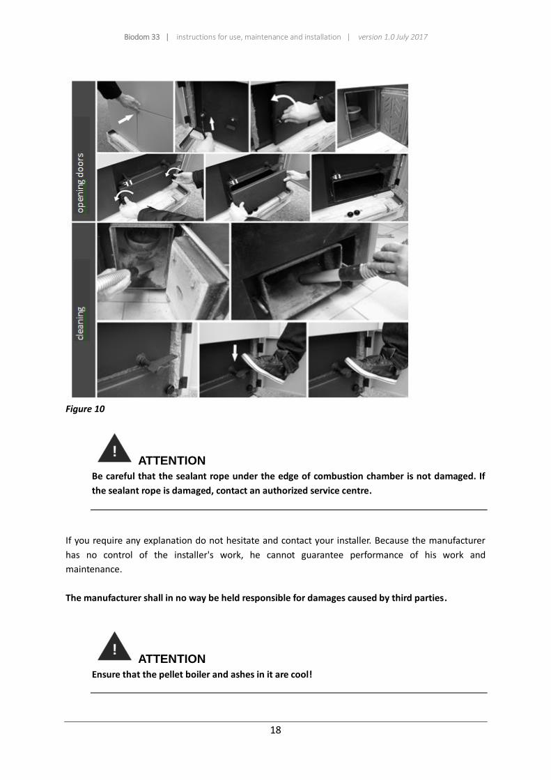
Once a month, remove the front door at the bottom of the exchanger on the right side of the boiler
and vacuum the inside (figure 10).
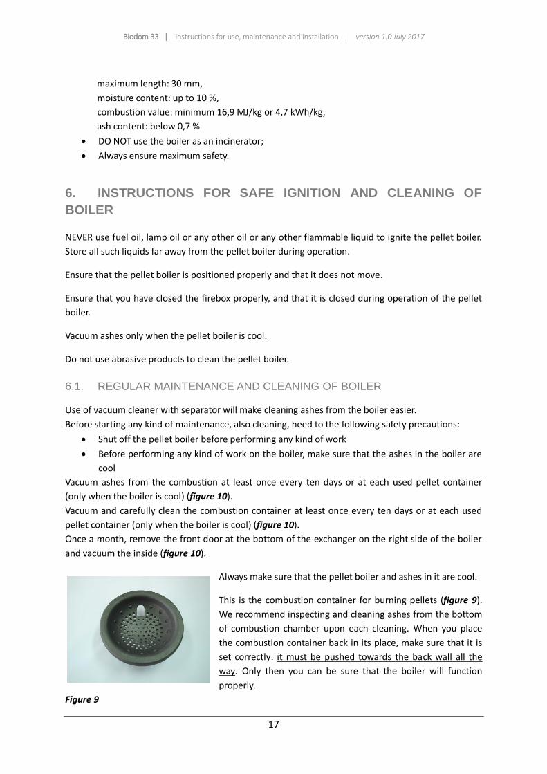
Always make sure that the pellet boiler and ashes in it are cool.
This is the combustion container for burning pellets (figure 9).
We recommend inspecting and cleaning ashes from the bottom
of combustion chamber upon each cleaning. When you place
the combustion container back in its place, make sure that it is
set correctly: it must be pushed towards the back wall all the
way. Only then you can be sure that the boiler will function
properly.
Figure 9
Biodom 33 | instructions for use, maintenance and installation | version 1.0 July 2017
18
Figure 10
ATTENTION
Be careful that the sealant rope under the edge of combustion chamber is not damaged. If
the sealant rope is damaged, contact an authorized service centre.
If you require any explanation do not hesitate and contact your installer. Because the manufacturer
has no control of the installer's work, he cannot guarantee performance of his work and
maintenance.
The manufacturer shall in no way be held responsible for damages caused by third parties.
ATTENTION
Ensure that the pellet boiler and ashes in it are cool!

Biodom 33 | instructions for use, maintenance and installation | version 1.0 July 2017
19
The combustion chamber must be cleaned after each used pellet container, vacuumed and/or
emptied of all impurities remaining after the pellets have burned.
Never put pellets which have not burned back in the pellet container or ash box.
6.2. CONTROL AND PARTS REQUIRING MAINTENANCE
CHECK THE FOLLOWING ITEM AND MAKE SURE THAT THE PELLET BOILER IS OPERATING PROPERLY.
THIS WILL INCREASE ITS EFFICIENCY AND THE EMITTED HEAT INTO THE SYSTEM WILL ALSO INCREASE:
Ensure that the pellet boiler and ashes in it are cool!
For perfect cleaning, vacuum ashes from beneath the combustion container and from
combustion chamber every week or at each 200 kg pellet container used (whichever comes
sooner). Use a broom or a brush to clean firebox walls.
Clean the fan for extraction of smoke gases by removing fan protection and cleaning fan
blades with a broom or a brush.
GENERAL BOILER CLEANING AFTER THE END OF SEASON OR BEFORE THE START OF SEASON:
Ensure that the pellet boiler and ashes in it are cool!
Disconnect power supply!
At the end of heating season, disconnect the boiler from electrical network. It is very
important to clean and inspect the boiler, as described in the instructions.
Door seal, fitted with high-temperature resistant fitting material, can detach after prolonged
use. To reattach it, apply high-temperature fitting material on the back of the seal. This
ensures hermetic sealing of firebox doors.
FLUE CONNECTION – CHIMNEY (must be cleaned at the end of each season):
Ensure that the pellet boiler and ashes in it are cool!
Flue duct, chimney and chimney cover must be inspected and cleaned every year. Contact
your chimney sweep for professional service.
Biodom 33 | instructions for use, maintenance and installation | version 1.0 July 2017
20
6.3. ADDITIONAL MAINTENANCE
Your pellet boiler is a heat generator which uses pellets. Therefore, it requires a special type of
maintenance by authorized personnel of company BIODOM 27 d.o.o. each year.
Regular annual maintenance keeps the combustion device in good condition, ensures greater
efficiency, retains warranty and extends life expectancy of the device.
Type of work, described in the previous chapter, is advisable to perform after the end of heating
season. Their purpose is to check and ensure flawless operation of all components.
7. IMPORTANT SAFETY INFORMATION
You have purchased a product of the highest quality.
The supplier is at your disposal in transferring required information. Correct installation of
combustion device in accordance with instructions is important to prevent any poor functioning,
hazard or risk of fire.
Pellet boiler operates on the basis of negative pressure in the combustion chamber. Therefore, always
ensure that the flue connection is thermally sealed.
ATTENTION
In the event of fire in the flue pipe, all persons and animals must leave the area, then
immediately disconnect power supply from the main switch or socket (if it is possible
without risk) and call the fire department.
ATTENTION
Do not use fine cut wood to ensure operation and safety of the boiler.
ATTENTION
Do not use the pellet boiler as an incinerator.
8. PELLET QUALITY IS VERY IMPORTANT
The pellet boiler is designed for use with pellets. Because the market offer many types and
dimensions of pellets, it is very important to obtain pellets free from impurities. Make sure that you
use only pellets that are compact and dust-free. Ask your supplier for suitable pellets with 5 mm
Biodom 33 | instructions for use, maintenance and installation | version 1.0 July 2017
21
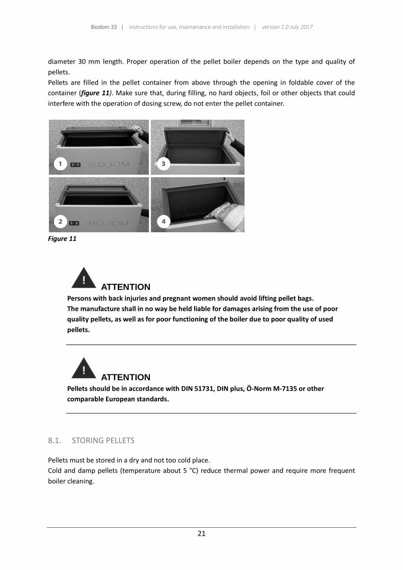
diameter 30 mm length. Proper operation of the pellet boiler depends on the type and quality of
pellets.
Pellets are filled in the pellet container from above through the opening in foldable cover of the
container (figure 11). Make sure that, during filling, no hard objects, foil or other objects that could
interfere with the operation of dosing screw, do not enter the pellet container.
Figure 11
ATTENTION
Persons with back injuries and pregnant women should avoid lifting pellet bags.
The manufacture shall in no way be held liable for damages arising from the use of poor
quality pellets, as well as for poor functioning of the boiler due to poor quality of used
pellets.
ATTENTION
Pellets should be in accordance with DIN 51731, DIN plus, Ö-Norm M-7135 or other
comparable European standards.
8.1. STORING PELLETS
Pellets must be stored in a dry and not too cold place.
Cold and damp pellets (temperature about 5 °C) reduce thermal power and require more frequent
boiler cleaning.
Biodom 33 | instructions for use, maintenance and installation | version 1.0 July 2017
22
ATTENTION
PELLETS SHOULD NOT BE STORED NEAR THE PELLET BOILER. Keep them at least 1/2 metre
away.
When handling pellets, be careful not to scatter them.
If you fill the pellet container with sawdust, it can block the pellet dosing system.
9. DESCRIPTION AND OPERATION OF CONTROL DEVICE
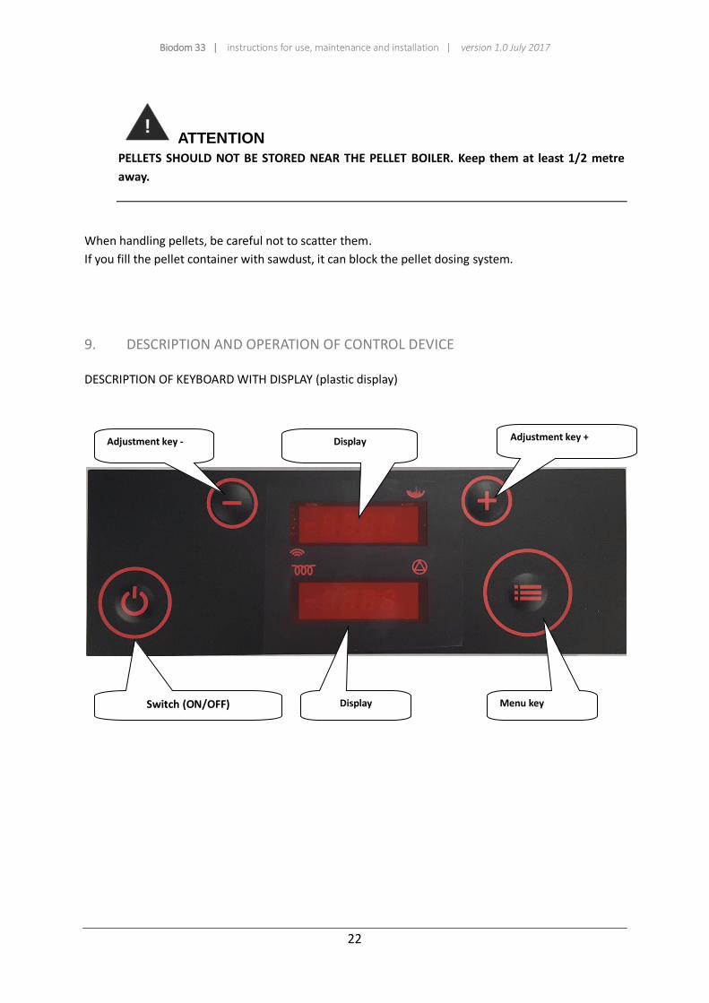
DESCRIPTION OF KEYBOARD WITH DISPLAY (plastic display)
Adjustment key -
Display
Adjustment key +
Switch (ON/OFF)
Display Menu key

Biodom 33 | instructions for use, maintenance and installation | version 1.0 July 2017
23
Display Function
upper display shows boiler status, chosen menu and indicates dosing
operation and operation in time programme
lower display shows current time, value of settings and parameters
and warning names
spark plug operation indicator
pump operation indicator
dosing operation indicator
Display during boiler operation in burning phase
Upper display: upper display alternately shows:
BURN and then P5D5, where Px means actual current operation power
and DX set operation power
Lower display:
lower display alternately shows:
Temperature of smoke gases: 155
Temperature of water in the boiler: B72
Temperature of return water: r45
Display during boiler standstill:
Upper display: OFF
Lower display:
Time: 18:35

Biodom 33 | instructions for use, maintenance and installation | version 1.0 July 2017
24
Button Function
ON/OFF button
Press and hold to turn the boiler on/off.
Short press to return to basic display.
+
Button UP
Press during operation to increase set power.
When pressing MENU button beforehand, this button increases
desired water temperature in the boiler. In menu mode, we select
desired submenu by pressing.
-
Button DOWN
Press during operation to decrease set power.
When pressing MENU button beforehand, this button decreases
desired water temperature in the boiler. In menu mode, we select
desired submenu by pressing.
MENU button
Short press in basic display shows set value of water temperature in
the boiler, which can then be modified with buttons + and -.
Press and hold for at least 2 seconds to activate menu mode.
Press and hold for at least 4 seconds to enter advanced menu
settings. Subsequent pressing of the button display menu choices.
Use buttons + and - to select parameters in submenus. Short press
MENU button and set value of parameter starts flashing, which can
then be modified with buttons + and -.
Short press ON/OFF button and hold MENU button to scroll all menu
choices and return to basic display.

Biodom 33 | instructions for use, maintenance and installation | version 1.0 July 2017
25
Biodom 33 | instructions for use, maintenance and installation | version 1.0 July 2017
26
9.1. BOILER DURING OPERATION
The display shows current operation phase (e.g. TestFire, HeatUp etc.). Upper display shows set and
actual boiler power alternately every 5 seconds.
Press button UP to increase set power value, and press button DOWN to decrease it.
Press MENU button to display set water temperature in the boiler. You can modify it with buttons UP
and DOWN.
The boiler operates at set power, until water temperature in the boiler reaches modulation threshold
or until smoke gases reach limits. In first case, Regu H20 is displayed, and in second Regu Gas.
In case of power outage for less than 2 minutes, the boiler resumes normal operation when power
supply restores. If the outage lasts more than 2 minutes, the boiler automatically performs safety
shutdown and cooling and then restarts.
9.2. BOILER SHUTDOWN
When pressing and holding the ON/OFF button for more than half a second (during boiler operation),
the display shows ON, and the boiler starts shutdown sequence once the button is released. Dosing
screw turns off and the display indicates STOP FIRE. Fans operate at high speed to prevent excessive
increase of water temperature in the boiler. When the boiler cools down under set temperature, fans
switch to maximum speed and blow out the last parts from the firebox. Display indicates OFF.
9.3. BOILER ACTIVATION
When pressing and holding the ON/OFF button for more than half a second (boiler at standstill), the
display shows OFF, and the boiler begins activation sequence once the button is release. Display
indicates TESTFIRE. Fans operate at high speed to clean the firebox. Dosing screw is at standstill,
spark plug is heating.
If the firebox temperature is low, sequence HEAT UP begins, where pellets are dosed quickly and fans
stand still. Then sequences Fuel IGNI and TEST IGNI start, until the boiler reaches conditions for
transition to burning phase (BURN).
ATTENTION
By pressing and holding MENU button for 2 seconds (release the button when tH20 displays),
the display indicates current water temperature in the boiler. By pressing button UP or button
DOWN you select display of other temperatures and fan status .

Biodom 33 | instructions for use, maintenance and installation | version 1.0 July 2017
27
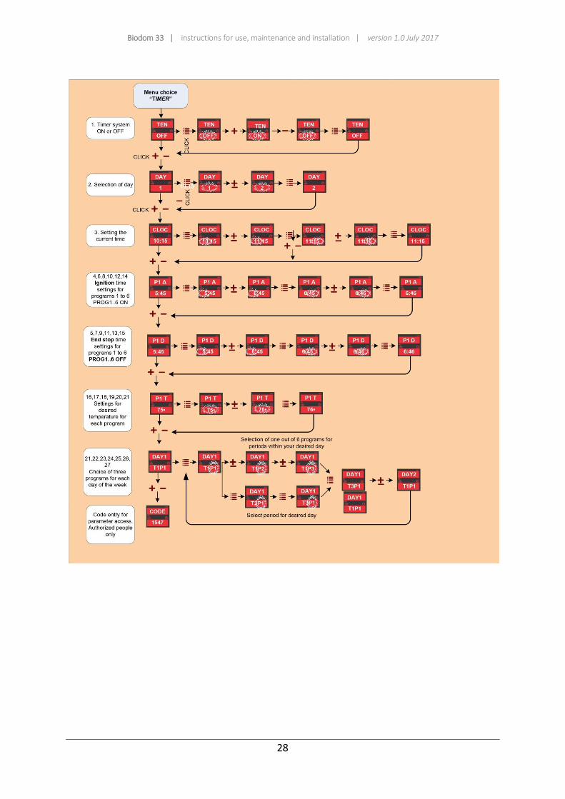
9.4. TIME PROGRAMME SETTING
Press and hold (until TEN displays) MENU button to access time programme menu.
By setting ON or OFF, the time programme activates or deactivates.
Accurate time and current day of the week (1 is Monday etc.) must be set and then, 6 programme
periods and temperatures must be programmed.
Each of 6 time period is determined by start (P1a – programme 1 start time) and end time (P1d –
programme 1 end time). In this period, the boiler is active and operates by maintaining water
temperature in the boiler (P1t).
Then select up to 3 time periods for each day of the week.
Example (Tuesday): upper display shows DAY2, and lower P1, P3 and P6, which means that the boiler
will be active on Tuesday in periods, programmed with programmes P1, P3 and P6.
Figure 12: Diagram of timer settings
Biodom 33 | instructions for use, maintenance and installation | version 1.0 July 2017
28

Biodom 33 | instructions for use, maintenance and installation | version 1.0 July 2017
29
9.5. INDICATIONS AND MESSAGES ON DISPLAY
Indication on
display
Explanation of message and status of the boiler
OFF
1 2 :5 3
The boiler is at a standstill.
°OFF
1 2 :5 3
The boiler is at a standstill, but the time programme is active and will start
automatically, as set with time programme.
TEST
FIRE
The boiler checks if there is a flame in the firebox and for proper combustion this
sequence starts after power supply outage.
Hea t
UP
In ignition phase, when the dosing screw filled the firebox, spark plug heats
pellets to ignition.
Fuel
IGNI
After Heat up phase, the boiler ignites pellets. No dosing in this phase.
TST
IGNI
At the end of ignition phase, the boiler shuts off the spark plug and tests, if the
ignition was successful and if combustion is correct and temperatures rise
correctly.
BURN
1 2 3 °
Burning phase (normal work phase). Lower display shows temperature of smoke
gases at exit from the boiler.
BURN
B78°
Burning phase. Lower display shows water temperature in the boiler.
BURN
R48°
Burning phase. Lower display shows temperature of return water.
P5D5
R48°
Burning phase. Upper display shows current power of the boiler (Px) and set
power of the boiler (Dx).
CLN
FIRE
Cleaning phase. Fans blow out ash and other residues from the firebox. This
phase starts automatically from time to time during burning phase.
FIRE
STOP
The boiler is in stopping sequence and is cooling down.
Biodom 33 | instructions for use, maintenance and installation | version 1.0 July 2017
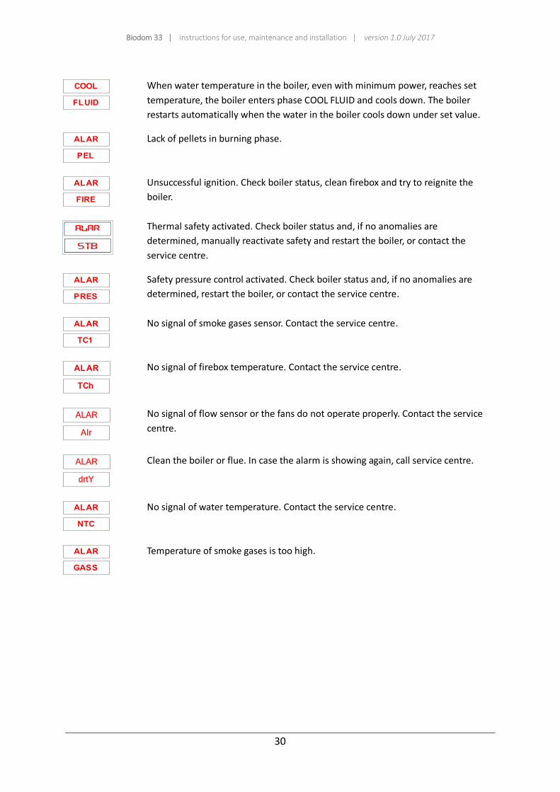
30
COOL
FLUID
When water temperature in the boiler, even with minimum power, reaches set
temperature, the boiler enters phase COOL FLUID and cools down. The boiler
restarts automatically when the water in the boiler cools down under set value.
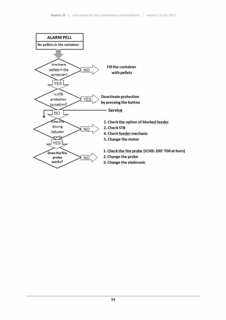
ALAR
PEL
Lack of pellets in burning phase.
ALAR
FIRE
Unsuccessful ignition. Check boiler status, clean firebox and try to reignite the
boiler.
Thermal safety activated. Check boiler status and, if no anomalies are
determined, manually reactivate safety and restart the boiler, or contact the
service centre.
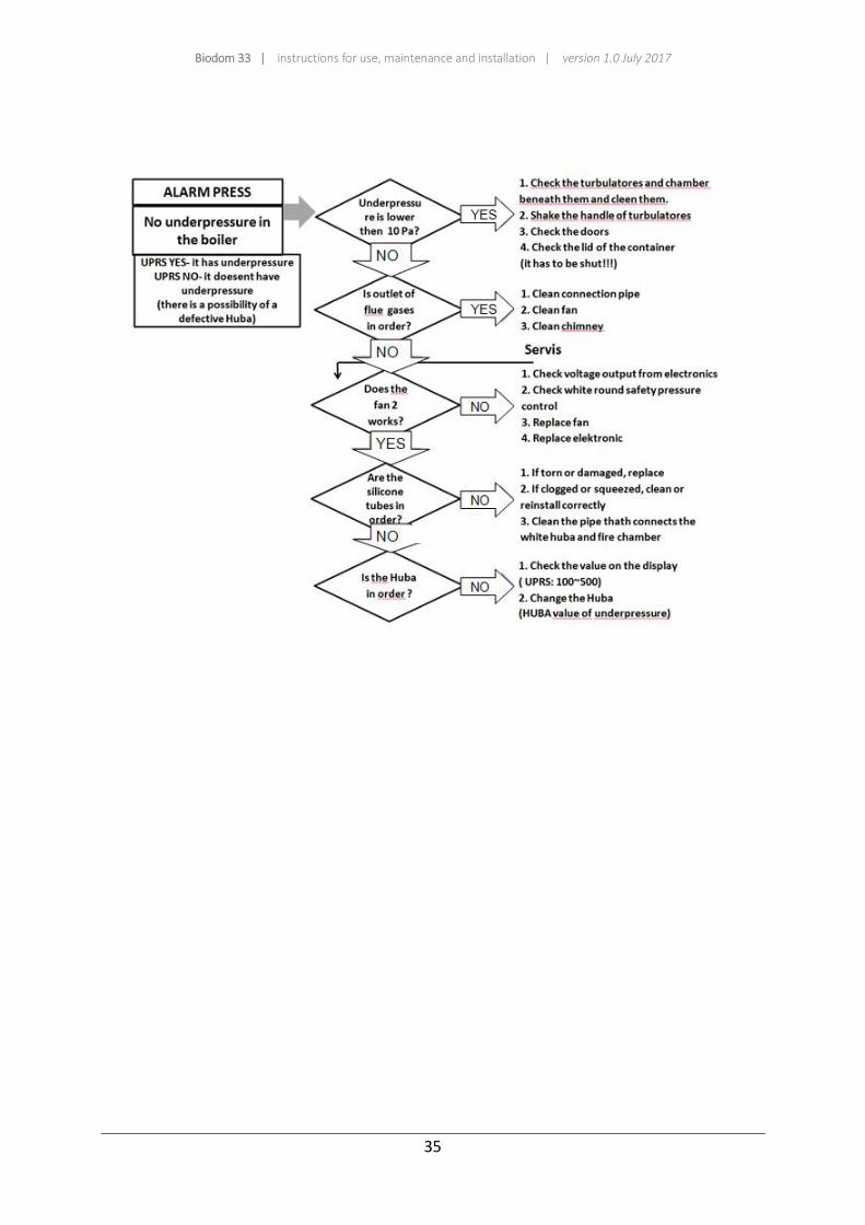
ALAR
PRES
Safety pressure control activated. Check boiler status and, if no anomalies are
determined, restart the boiler, or contact the service centre.
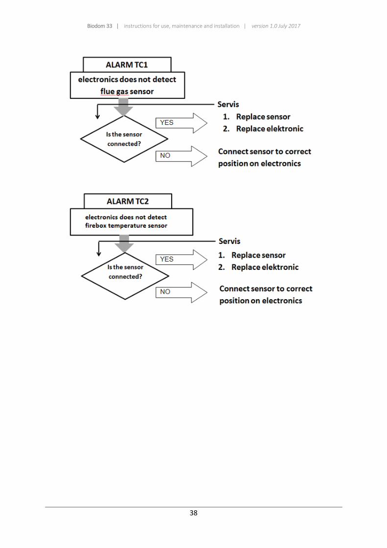
ALAR
TC1
No signal of smoke gases sensor. Contact the service centre.
ALAR
TCh
No signal of firebox temperature. Contact the service centre.
ALAR
AIr
No signal of flow sensor or the fans do not operate properly. Contact the service
centre.
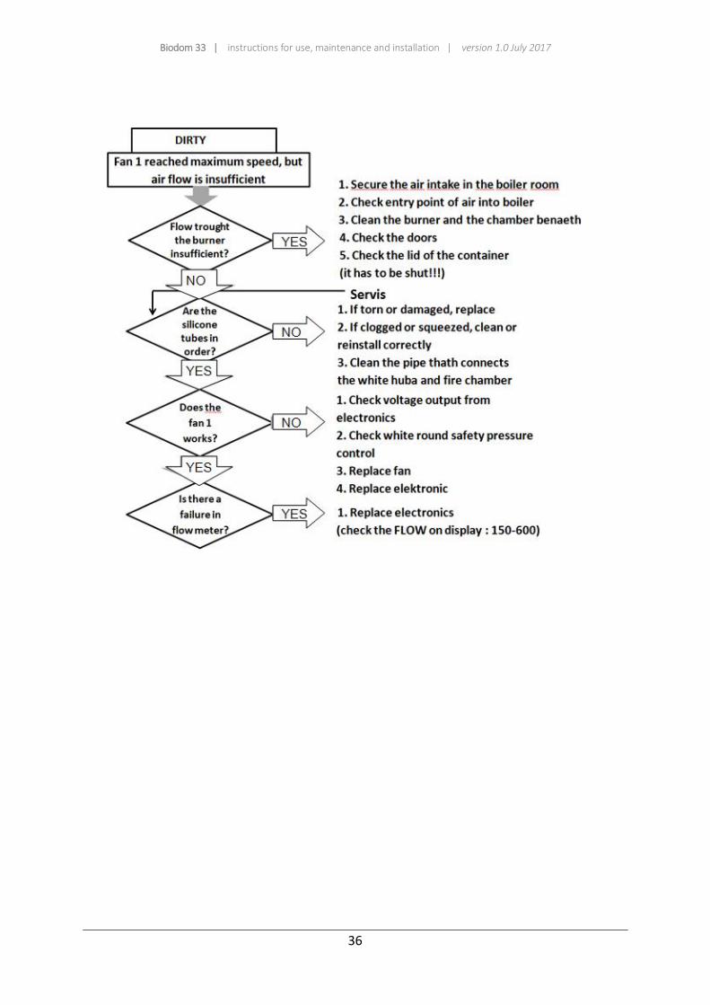
ALAR
drtY
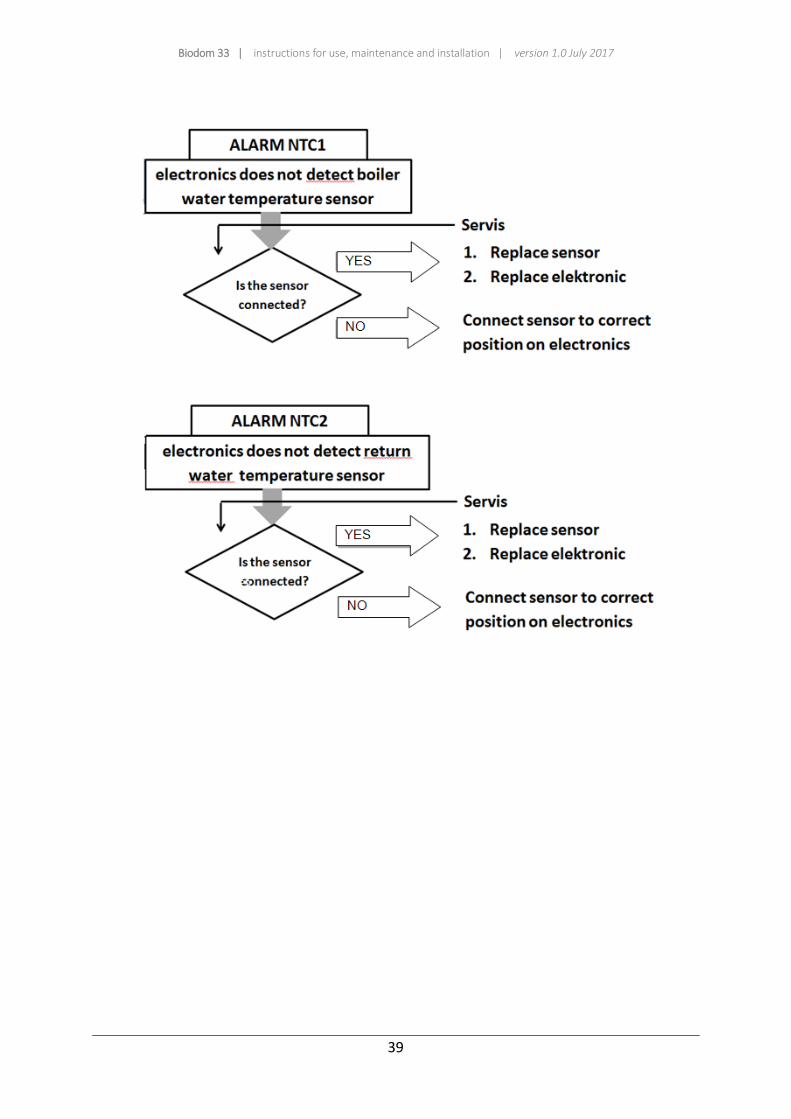
Clean the boiler or flue. In case the alarm is showing again, call service centre.
ALAR
NTC
No signal of water temperature. Contact the service centre.
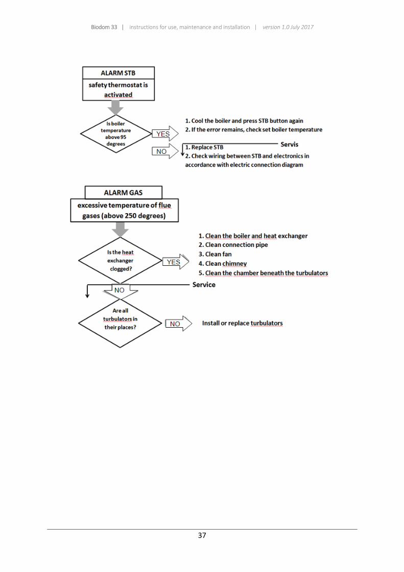
ALAR
GASS
Temperature of smoke gases is too high.
Biodom 33 | instructions for use, maintenance and installation | version 1.0 July 2017
31
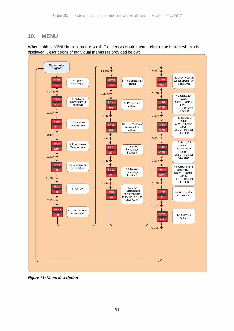
10. MENU
When holding MENU button, menus scroll. To select a certain menu, release the button when it is displayed. Descriptions of individual menus are provided below:
Figure 13: Menu description
Biodom 33 | instructions for use, maintenance and installation | version 1.0 July 2017
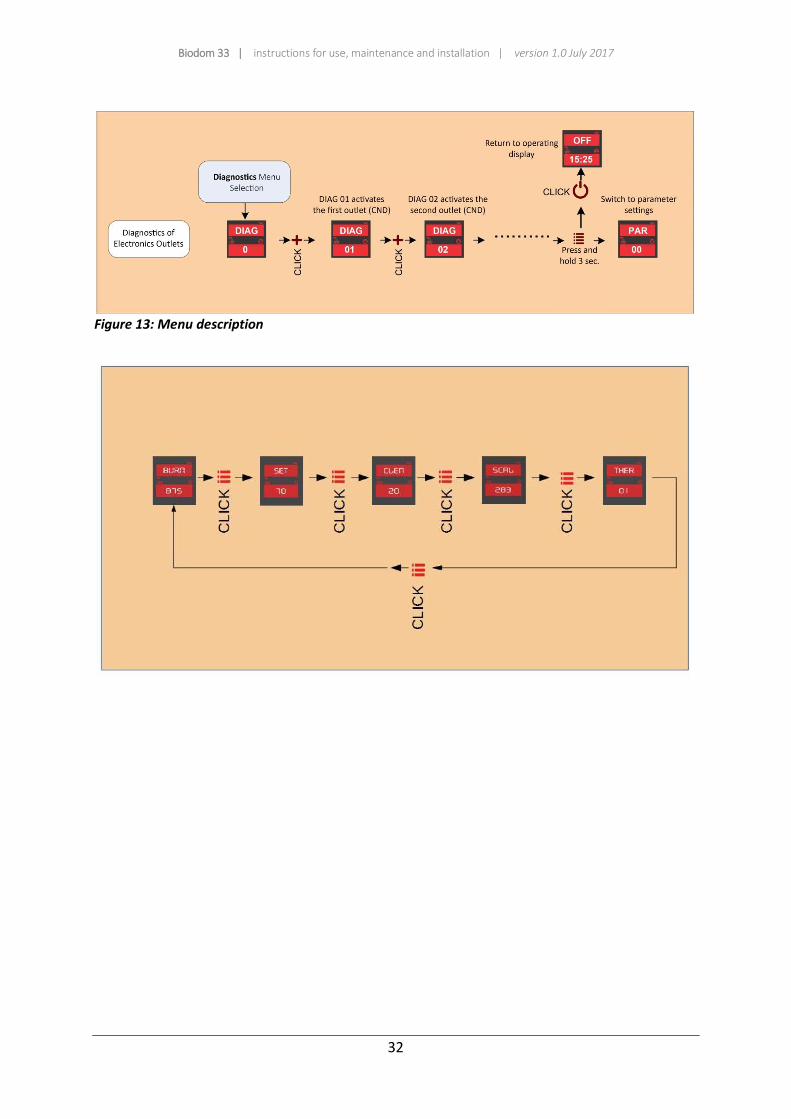
32
Figure 13: Menu description
Biodom 33 | instructions for use, maintenance and installation | version 1.0 July 2017
33
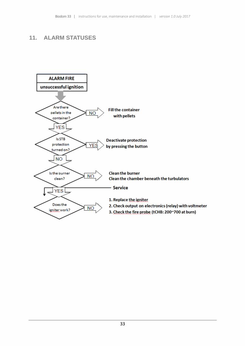
11. ALARM STATUSES
Biodom 33 | instructions for use, maintenance and installation | version 1.0 July 2017
34
Biodom 33 | instructions for use, maintenance and installation | version 1.0 July 2017
35
Biodom 33 | instructions for use, maintenance and installation | version 1.0 July 2017
36
Biodom 33 | instructions for use, maintenance and installation | version 1.0 July 2017
37
Biodom 33 | instructions for use, maintenance and installation | version 1.0 July 2017
38
Biodom 33 | instructions for use, maintenance and installation | version 1.0 July 2017
39
Biodom 33 | instructions for use, maintenance and installation | version 1.0 July 2017
40
12. INFORMATION REGARDING DESTRUCTION AND DISPOSAL OF BOILER
Destruction and disposal of pellet boiler is sole responsibility of the owner, who must act in accordance with laws in force in his country regarding safety, respect and protection of environment. Destruction and disposal of pellet boiler can be entrusted to a third person with licence or authorization for disposal and destruction of aforementioned materials. INDICATION: in any case, you must adhere to and respect laws in force in the county in which the pellet boiler is installed.
ATTENTION
All disassembled parts must be properly disposed of:
remove all electrical parts;
disconnect the battery from control device;
dispose of the battery of control device in accordance with norms in appropriate containers;
dispose of the boiler core or sell it as scrap metal.
ATTENTION
Disposed pellet boiler in accessible areas can present a serious danger for people and animals. Owner of the boiler is always responsible for damage caused.
Once the boiler is destructed, CE mark, Instructions for use, maintenance and installation and other documents regarding the boiler must also be destroyed.
Biodom 33 | instructions for use, maintenance and installation | version 1.0 July 2017
41
13. WARRANTY CONDITIONS
OVERVIEW:
For the warranty to be completely valid, as set forth in Directive EEC 1999/44/E (42/2002), the user must carefully heed to instructions in this document, namely:
Use the pellet boiler in its limits, in accordance with the conditions set forth in the instructions for use;
Maintain the pellet boiler in a diligent and constant manner;
Regard all safety precautions in accordance with laws in force;
Avoid any unprofessional tampering with the boiler;
Use only original spare parts.
WARRANTY TIME CONDITIONS: Warranty for all Biodom products is valid for 24 months from the date of first start-up, given that a regular maintenance inspection is performed no later than 12 months from the date of start-up.
GENERAL WARRANTY CONDITIONS: 1. We declare:
that the product will function flawlessly in the warranty period, if used in accordance with the purpose of use, and if enclosed Instructions for use and maintenance will be adhered to;
that, in the warranty period, company Biodom will, through authorized service companies, resolve all faults/defects, due to which the device is not working in accordance with purpose, no later than 45 days from written report of fault or defect;
that a product, not repaired in the aforementioned deadline, will be, at the request of warranty holder, replaced with a new one, and the warranty period will extend for the time of the repair;
that authorized service company guarantees warranty conditions with signature and stamp on published warranty.
2. Calling on the warranty: Warranty is valid under the condition that:
The customer possesses a valid document (receipt), issued by salesman.
The combustion device was installed by a qualified and/or trained person, who determines if the device meets all technical characteristics of the system where the device will be installed to, and must be necessarily in accordance with requirements set forth in the instructions.
The pellet boiler is used in accordance with the instructions for use. Warranty is called on at the salesman, where you have purchased the device. Upon claiming fault, provide an accurate description of fault – defect. 3. Period of guaranteeing service and spare parts:
warranty period, in which we guarantee service and spare parts for undisturbed use of the product, is 7 years from the day of first start-up;
in case of replacing production models Biodom, we guarantee spare parts for your product for 3 years;
after 7 years, spare parts will be available, but they may be available in different colour than your product.
4. Warranty is void or does not cover damages, caused by:
Weather, chemical or electrochemical influences, lightning strikes, elementary accidents and/or natural disasters, incorrect use of the product, insufficient maintenance,
Biodom 33 | instructions for use, maintenance and installation | version 1.0 July 2017
42
modifications to the product or tampering with the product, unsuitable or inefficient flue and other reasons not connected to the product, such as incorrect or unsuitable installation;
Burning of materials, which do not correspond with the type of material given in these instructions;
Any kind of damage caused by/during transport. Therefore, carefully inspect delivered goods upon reception. If it is damaged, immediately inform the salesman, and record the damage on admission document or supply order;
If the start-up was performed by a company without appropriate authorization for Biodom products;
If the product has been tampered with or repaired by an unauthorized person;
If the user does not comply with the instructions for use and maintenance;
If defects or faults arise on the heating device Biodom due to defects on equipment of other manufacturers.
Liability of company Biodom 27 d.o.o. is limited to unit supply. Unit must be installed properly in accordance with manufacturer instructions, as well as with laws in force. Installation must be performed by qualified personnel, defined by the manufacturer or representative/salesman1 (and/or under his supervision and liability), who assumes full responsibility for final installation and subsequent correct operation of installed product. In case of non-fulfilment of conditions, company Biodom 27 d.o.o. is not liable in any case. 1 As representative/salesman is considered any natural person or legal entity authorized for sales of products to end users of this warranty. NOTE: Biodom 27 d.o.o. shall not be held liable for any damage and consequences, even if these are a consequence of replacement of malfunctioning part of the boiler. Biodom 27 d.o.o. guarantees that all of its products are made of materials of highest quality and with manufacturing processes, which ensure perfect efficiency. If during normal use, there should be any defective or malfunctioning parts, they must be replaced.
PARTS, SUBJECT TO NORMAL WEAR, NOT COVERED BY WARRANTY:
Seals and cast iron parts, which do not show any signs of faults, which could be attributed to manufacturing error;
Changes in colour, cracks and small dimensional modifications are not substantiated and do not present grounds for rejection, as they are a consequence of natural characteristics of materials.
LIABILITY: Biodom 27 d.o.o. shall not recognize any compensation for direct or indirect damage caused by or related to the product.
SERVICE DURING WARRANTY PERIOD: Biodom 27 d.o.o. handles problems regarding warranty only through its authorized persons.
COMPETENT COURT: The Court of Koper shall have jurisdiction for settling disputes. In the event of replacement of parts, the warranty is not extended. No reimbursement is acknowledged for the period of time, during which the product could not be used.

Biodom 33 | instructions for use, maintenance and installation | version 1.0 July 2017
43
Biodom 27 d.o.o. is not liable for any mistakes in the instructions. We reserve the right to changes without any prior notice.
Biodom 33 | instructions for use, maintenance and installation | version 1.0 July 2017
44
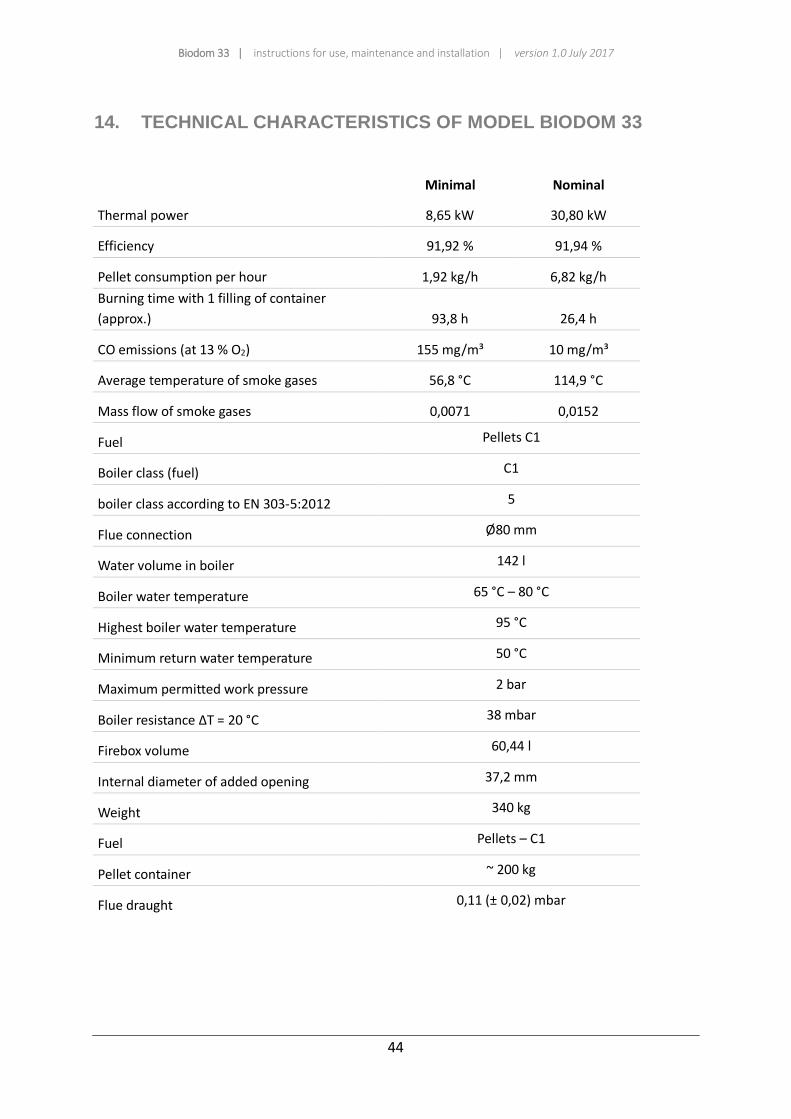
14. TECHNICAL CHARACTERISTICS OF MODEL BIODOM 33
Minimal Nominal
Thermal power 8,65 kW 30,80 kW
Efficiency 91,92 % 91,94 %
Pellet consumption per hour 1,92 kg/h 6,82 kg/h
Burning time with 1 filling of container
(approx.) 93,8 h 26,4 h
CO emissions (at 13 % O2) 155 mg/m³ 10 mg/m³
Average temperature of smoke gases 56,8 °C 114,9 °C
Mass flow of smoke gases 0,0071 0,0152
Fuel Pellets C1
Boiler class (fuel) C1
boiler class according to EN 303-5:2012 5
Flue connection Ø80 mm
Water volume in boiler 142 l
Boiler water temperature 65 °C – 80 °C
Highest boiler water temperature 95 °C
Minimum return water temperature 50 °C
Maximum permitted work pressure 2 bar
Boiler resistance ΔT = 20 °C 38 mbar
Firebox volume 60,44 l
Internal diameter of added opening 37,2 mm
Weight 340 kg
Fuel Pellets – C1
Pellet container ~ 200 kg
Flue draught 0,11 (± 0,02) mbar

Biodom 33 | instructions for use, maintenance and installation | version 1.0 July 2017
45
Voltage 220 V
Current at maximum electrical consumption during boiler operation 1,80 A
frequency 50 Hz
Maximum consumption of power during boiler operation 78,5 W
Minimum consumption of power during boiler operation 19 W
Maximum consumption of power during boiler ignition 328,5 W
Safety level IP20
Boiler operates with two fans
Boiler operates only in manner of negative pressure combustion
Boiler operates without condensation conditions
Noise does not exceed 70 dB
15. DIMENSIONS OF BOILER BIODOM 33
Biodom 33 | instructions for use, maintenance and installation | version 1.0 July 2017
46
__________
16. INSTRUCTIONS FOR INSTALLERS
__________
This part of the instructions is intended solely for installer and contains all key information for
installation and connection of combustion device Biodom 33.

Biodom 33 | instructions for use, maintenance and installation | version 1.0 July 2017
47
17. BOILER CONNECTION INSTRUCTIONS
The advantage of the pellet boiler Biodom 33 in the easy installation and simple programming. BIODOM pellet boiler 33 has an integrated electronic pump, which allows the adjustment of the speed in relation to the central heating system. This option enables the implementation of a simple central heating system, which is used to regulate the radiator thermostatic valves. Such a system does not require any other control (thermostat, automatic, complicated boiler rooms .....) (Scheme 1 or 2), but itself is equipped with a timing controller (timer "TEN"), which allows the different regimes at different temperatures of the boiler water. The solution provides micro control for each room separately (different places-different temperatures) and heating time can be controlled with a timer (Timer "TEN") on the boiler.
In case where the pellet boiler BIODOM 33 is mounted on an old installation where the central heating system is carried out with a single loop in different floors, it is recommended to install on all radiators thermostatic valves and set up the boiler room in accordance with the scheme no. 1 (in the case of heating and preparation of hot water, the boiler room is carried out in accordance with the scheme no. 2).
The advantage of such a system is the highest system efficiency, easy installation, low cost installation and easy handling for the user
To connect boiler Biodom 33 to central heating system you must check:
Correct installation of pipelines of central heating (pipeline dimensions, air extraction, pipe
system functionality, adequacy of heating system according to boiler power).
Distribution units (pump functionality, closing valves functionality, electrical zone valves func-
tionality, mixed valves functionality…).
Ensured inlet of air into the space where Biodom 33 combustion device is installed. Inlet
must be executed in a manner, so that it cannot be closed and must, at any moment, enable
supply of fresh air – oxygen for burning into space. Unsuitable solutions are slightly opened
windows or open doors, supply of air through a duct along the flue from the roof is also un-
suitable.
Voltage of electrical connection for combustion device Biodom 33 must be 230 V / 50 Hz
(given in technical data for boiler Biodom 33).
Inspection of outlet of smoke gases – flue. Condition for connection is a consent from chim-
ney sweep, with which a chimney sweep ensure suitability of the flue for combustion device
Biodom 33.
In placing and connecting the combustion device to central heating system, the installer must adhere
to the following:
Boiler Biodom 33 must be positioned horizontally, in length and depth.
Distances, according to the enclosed drawing, must be regarded (see figure 1, page 8).
In cases of older installation on return line to combustion device Biodom 33, a cleaning ele-
ment with closing valves is installed.
Boiler Biodom 33 is fitted with
-with non-return valve on the non–return pipe
-electronic pump

Biodom 33 | instructions for use, maintenance and installation | version 1.0 July 2017
48
- the expansion (expansion) tank volume of 18 liters which is sufficient for the system of
central heating, which contains up to 200 liters of heating water in the system (boiler
contains 142 liters of heating water). In the case where the system is more than 58 liters of
the heating water the installer must ensure a further expansion tank for the quantity of
heating water in the system over 200 liters (the size of the expansion tank must be sized to a
minimum of 9% of the amount of water in the system "300 liters of water in the heating
system, , the minimum size of the additional expansion tank must be 9 liters "). The
expansion tank must be installed on the boiler Biodom 33 without locking elements.
safety valve of 2.5 bar on return line.
A filling release tap must be installed on the right side of the boiler, on connection DN20.
Minimal pressure of heating water in boiler of 0.7 bar is ensured.
In case where there are many heating loops (two direct loops or mix loops for radiator heat-
ing, boiler heating, convector heating), connection scheme nr. 3 is always used, where it is
necessary to use a hydraulic switch.
Boiler must be fitted with pressure gauge for pressure of heating water in the boiler, i.e. on
pipeline before each closing valve (enable that the pressure gauge indicates pressure in the
boiler and system; in the time of filling "there cannot be a closing element, which could pre-
vent indication of pressure in the boiler in the time of filling"). On the right side of Biodom 33
is a provided DN15 connection for filling release tap. Filling release tap is intended for filling
or emptying the heating system and boiler.
When connecting the boiler Biodom 33 to central heating system you must use mechanical
elements, which prevent uncontrolled circulation of hot heating water through the boiler
(gravity block, spring non-return valve, solenoid zone valve, electromotor zone valve...). goal
of protection is to ensure amount of heating water flow through the boiler (minimal flow
through the boiler must be over 300 l/h).
When distribution of heating water is regulated by three-way mix valve (floor heating,
weather controlled regulation, where water flow on boiler heating loop is reduced), the sys-
tem is executed with fitted hydraulic switch.
When a three-way mix valve is used (for floor or radiator heating, only in case of only one
mixing heating loop), connection of boiler Biodom 33 is always executed according to scheme
nr. 3, where a hydraulic switch is built into the installation on heating cycle.
Flue connection must executed in accordance with instruction limiting maximum length of
connection pipe Ø 80 (5 m) and that 90-degree joints are considered as resistance on connec-
tion, which reduces length of connection pipe for 1 m (example: if there are 2 joints on flue
connection, the connection cannot exceed length of 3 m). Flue connection must be fitted
with joints with inspections holes for cleaning (see figure 3, page 11). Joints must be out of at
least 3 segments (joints with three or more segments enable smooth flow of smoke gases
through joint), it is prohibited to use joints with two segments (joints with two segments cre-
ates resistance in flow of smoke gases) (see figure 6, page 12).
If the flue connection is longer as set forth in the instructions, the installer must use a reduc-
ing element (from Ø 80 female connection to Ø 130 female connection) immediately behind
the fan, and the connection must be made with a pipe Ø 130.
Biodom 33 | instructions for use, maintenance and installation | version 1.0 July 2017
49
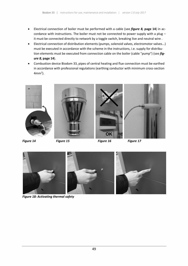
Electrical connection of boiler must be performed with a cable (see figure 8, page 14) in ac-
cordance with instructions. The boiler must not be connected to power supply with a plug –
it must be connected directly to network by a toggle switch, breaking live and neutral wire .
Electrical connection of distribution elements (pumps, solenoid valves, electromotor valves...)
must be executed in accordance with the scheme in the instructions, i.e. supply for distribu-
tion elements must be executed from connection cable on the boiler (cable "pump") (see fig-
ure 8, page 14).
Combustion device Biodom 33, pipes of central heating and flue connection must be earthed
in accordance with professional regulations (earthing conductor with minimum cross-section
4mm2).
Figure 14 Figure 15 Figure 16 Figure 17
Figure 18: Activating thermal safety
Biodom 33 | instructions for use, maintenance and installation | version 1.0 July 2017
50
18. CONNECTION SCHEMES
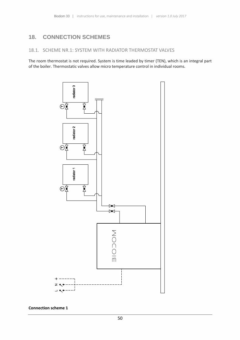
18.1. SCHEME NR.1: SYSTEM WITH RADIATOR THERMOSTAT VALVES
The room thermostat is not required. System is time leaded by timer (TEN), which is an integral part of the boiler. Thermostatic valves allow micro temperature control in individual rooms.
Connection scheme 1

Biodom 33 | instructions for use, maintenance and installation | version 1.0 July 2017
51
Electrical scheme 1
Biodom 33 | instructions for use, maintenance and installation | version 1.0 July 2017
52
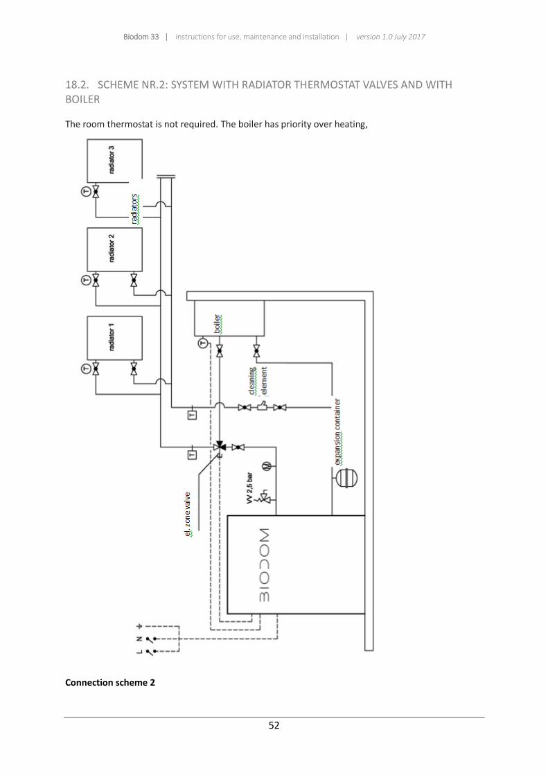
18.2. SCHEME NR.2: SYSTEM WITH RADIATOR THERMOSTAT VALVES AND WITH BOILER
The room thermostat is not required. The boiler has priority over heating,
Connection scheme 2
Biodom 33 | instructions for use, maintenance and installation | version 1.0 July 2017
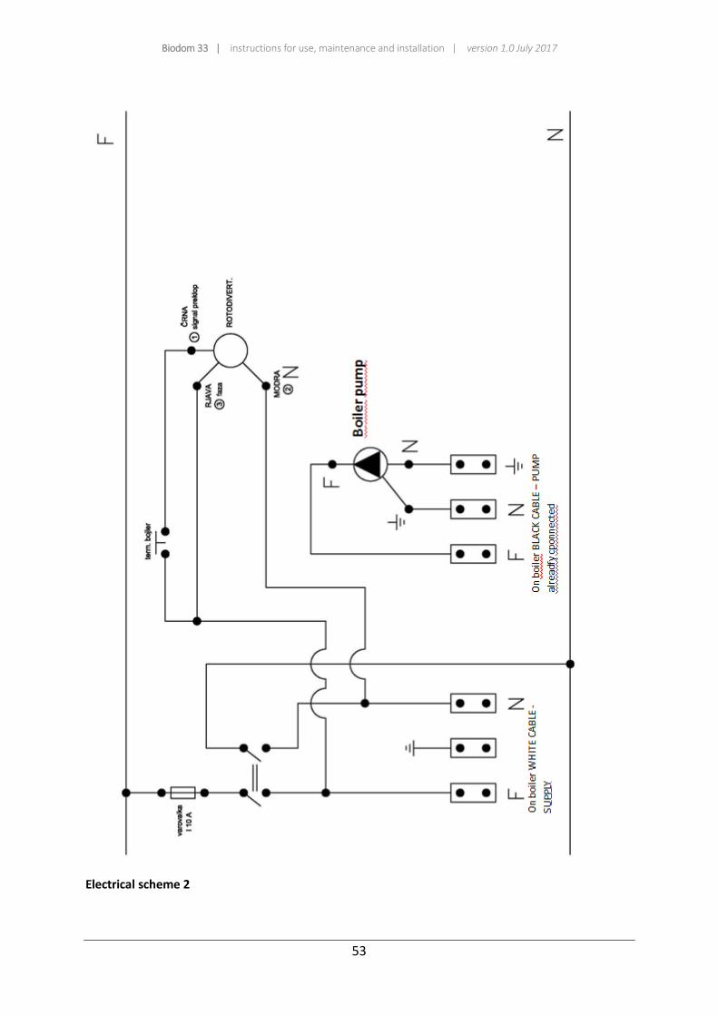
53
Electrical scheme 2
Biodom 33 | instructions for use, maintenance and installation | version 1.0 July 2017
54
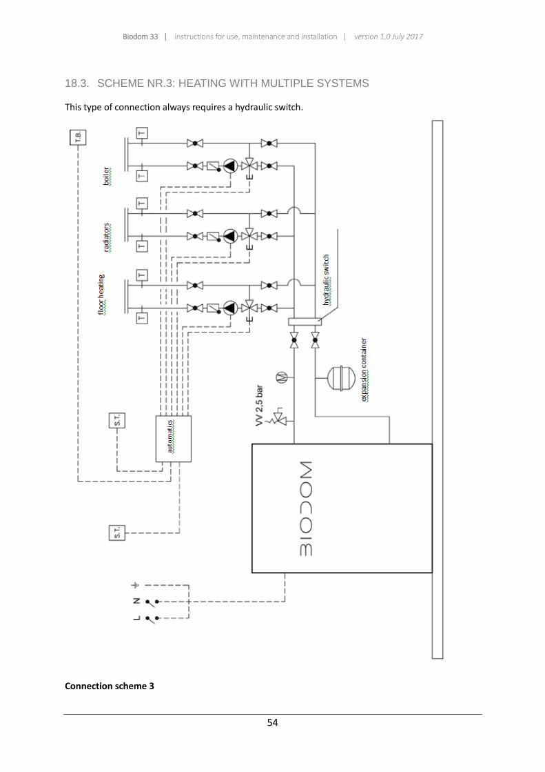
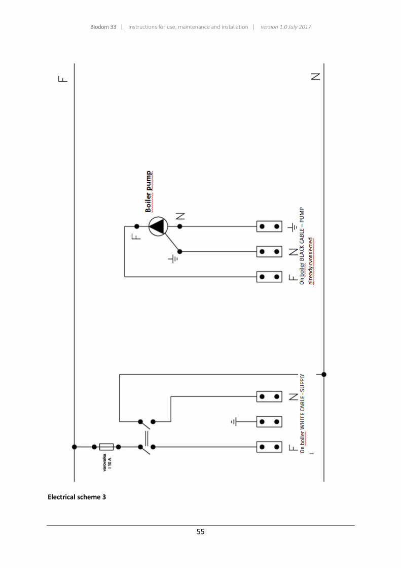
18.3. SCHEME NR.3: HEATING WITH MULTIPLE SYSTEMS
This type of connection always requires a hydraulic switch.
Connection scheme 3
Biodom 33 | instructions for use, maintenance and installation | version 1.0 July 2017
55
Electrical scheme 3

Biodom 33 | instructions for use, maintenance and installation | version 1.0 July 2017
56
__________
19. INSTRUCTIONS FOR FIRST START-UP
__________
Biodom 33 | instructions for use, maintenance and installation | version 1.0 July 2017
57
Biodom 33 is a combustion device for heating with pellets. Benefits of combustion device Biodom 33
lie in advanced technology that enables automatic identification of oxygen contents in air, automatic
identification of flue draught and automatic identification of pellet quality.
When one of the former factors is unsuitable, combustion device Biodom 33 indicates an alarm on
the display on unsuitability or fault for lacking (example: if the flue is clogged or does not provide
extraction of smoke gases, Biodom 33 displays "ALARM AIR").
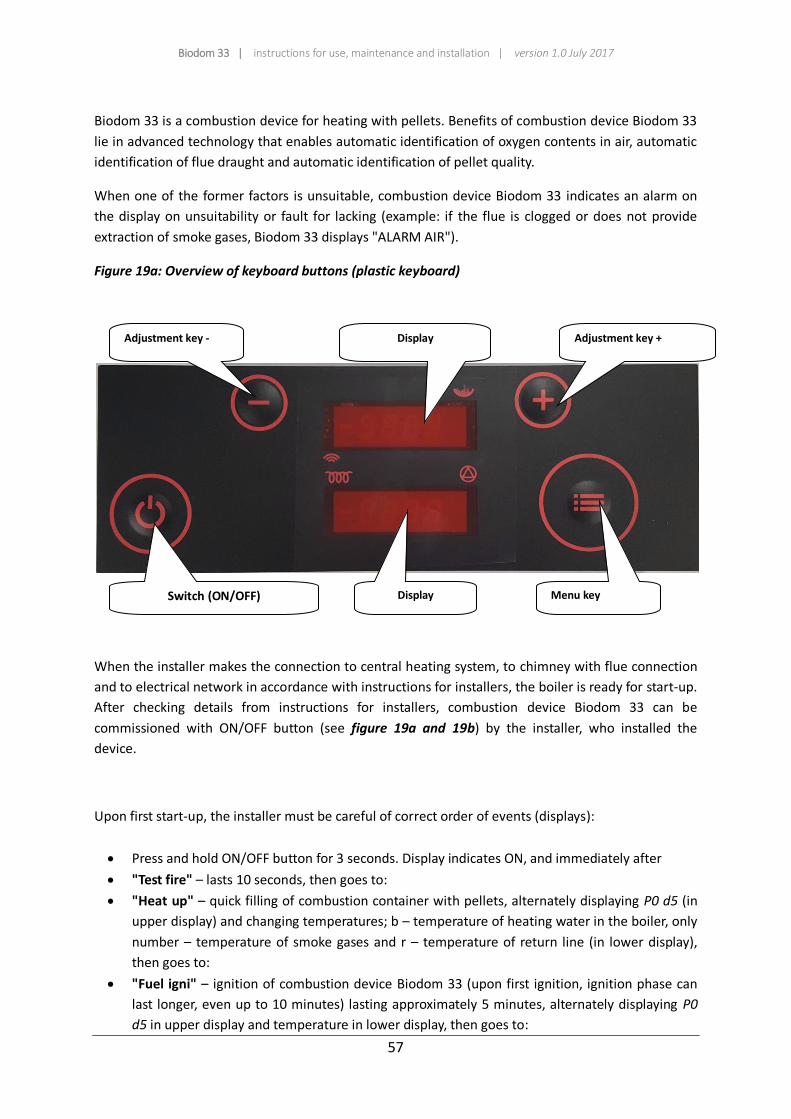
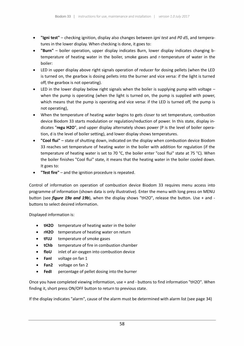
Figure 19a: Overview of keyboard buttons (plastic keyboard)
When the installer makes the connection to central heating system, to chimney with flue connection
and to electrical network in accordance with instructions for installers, the boiler is ready for start-up.
After checking details from instructions for installers, combustion device Biodom 33 can be
commissioned with ON/OFF button (see figure 19a and 19b) by the installer, who installed the
device.
Upon first start-up, the installer must be careful of correct order of events (displays):
Press and hold ON/OFF button for 3 seconds. Display indicates ON, and immediately after
"Test fire" – lasts 10 seconds, then goes to:
"Heat up" – quick filling of combustion container with pellets, alternately displaying P0 d5 (in
upper display) and changing temperatures; b – temperature of heating water in the boiler, only
number – temperature of smoke gases and r – temperature of return line (in lower display),
then goes to:
"Fuel igni" – ignition of combustion device Biodom 33 (upon first ignition, ignition phase can
last longer, even up to 10 minutes) lasting approximately 5 minutes, alternately displaying P0
d5 in upper display and temperature in lower display, then goes to:
Switch (ON/OFF)
Display Menu key
Adjustment key -
Display
Adjustment key +
Biodom 33 | instructions for use, maintenance and installation | version 1.0 July 2017
58
"Igni test" – checking ignition, display also changes between igni test and P0 d5, and tempera-
tures in the lower display. When checking is done, it goes to:
"Burn" – boiler operation, upper display indicates Burn, lower display indicates changing b-
temperature of heating water in the boiler, smoke gases and r-temperature of water in the
boiler:
LED in upper display above right signals operation of reducer for dosing pellets (when the LED
is turned on, the gearbox is dosing pellets into the burner and vice versa: if the light is turned
off, the gearbox is not operating).
LED in the lower display below right signals when the boiler is supplying pump with voltage –
when the pump is operating (when the light is turned on, the pump is supplied with power,
which means that the pump is operating and vice versa: if the LED is turned off, the pump is
not operating),
When the temperature of heating water begins to gets closer to set temperature, combustion
device Biodom 33 starts modulation or regulation/reduction of power. In this state, display in-
dicates "regu H2O", and upper display alternately shows power (P is the level of boiler opera-
tion, d is the level of boiler setting), and lower display shows temperatures.
"Cool flui" – state of shutting down, indicated on the display when combustion device Biodom
33 reaches set temperature of heating water in the boiler with addition for regulation (if the
temperature of heating water is set to 70 °C, the boiler enter "cool flui" state at 75 °C). When
the boiler finishes "Cool flui" state, it means that the heating water in the boiler cooled down.
It goes to:
"Test fire" – and the ignition procedure is repeated.
Control of information on operation of combustion device Biodom 33 requires menu access into
programme of information (shown data is only illustrative). Enter the menu with long press on MENU
button (see figure 19a and 19b), when the display shows "tH2O", release the button. Use + and -
buttons to select desired information.
Displayed information is:
tH2O temperature of heating water in the boiler
rH2O temperature of heating water on return
tFLU temperature of smoke gases
tChb temperature of fire in combustion chamber
floU inlet of air-oxygen into combustion device
FanI voltage on fan 1
Fan2 voltage on fan 2
FedI percentage of pellet dosing into the burner
Once you have completed viewing information, use + and - buttons to find information "tH2O". When
finding it, short press ON/OFF button to return to previous state.
If the display indicates "alarm", cause of the alarm must be determined with alarm list (see page 34)

Biodom 33 | instructions for use, maintenance and installation | version 1.0 July 2017
59
20. DECLARATION OF CONFORMITY
IZJAVA PROIZVAJALCA O SKLADNOSTI
DECLARATION OF CONFORMITY
Naziv proizvajalca/Producer:
Biodom 27 d.o.o.
OIC Hrpelje 4a, 6240 Kozina, Slovenia
Izjavlja, da v nadaljevanju opisani stroj/Declares that that the below mentioned
machine
Toplovodni kotel na trdo gorivo/Solid fuel hot water boiler
Tip/Type: BIODOM 33
Kotel na pelete/ pellet boiler
Serijska številka/serial number:
leto proizvodnje/year of production:
Ustreza osnovnim zdravstvenim in varnostnim zahtevam direktiv/ Conforms to the
following CE directives:
Direktiva/Directive 2006/42/CE o strojih/on machinery
Direktiva/Directive 2014/35/ES o nizkonapetostni opremi/on low voltage equipment
Direktiva/Directive 2014/30/ES o elektromagnetni združljivosti/on electromagnetic
compatibility (EMC)

Biodom 33 | instructions for use, maintenance and installation | version 1.0 July 2017
60
Harmonizirani standardi/Harmonised standards:
EN ISO 12100-1:2004 and A1:2010
EN ISO 12100-2:2004 and A1:2010
EN 303-5:2012
EN 60204-1:2006 and A1:2009
EN 61000-6-3:2007
EN 61000-6-2:2005
EN 61000-3-3:A1 2002
EN 61000-3-3:A2 2006
Preizkus naprave je opravila Kiwa Cermet Italia S.p.A., Viale Venezia, 45 31020 San
Vendemiano (TV), številka preizkusa je 130402174./ The test of the pellet stove was carried
out by the Kiwa Cermet Italia S.p.A., Viale Venezia, 45 31020 San Vendemiano (TV), the
number of the report is 130402174.
Tehnična dokumentacija se hrani na naslovu OIC Hrpelje 4 a, 6240 Kozina. Oseba,
zadolžena za sestavljanje tehnične dokumentacije je Anton Kavčič./ The technical
documentation is stored at the OIC Hrpelje 4ª, 6240 Kozina. The person responsible for
compiling the technical documentation is Anton Kavčič.
Kozina, 15.02.2017
Biodom 27 d.o.o.
Anton Kavčič, director
Biodom 33 | instructions for use, maintenance and installation | version 1.0 July 2017
61
BIODOM 27 d.o.o.
OIC Hrpelje 4a
6240 Kozina, Slovenia
Tel.: +386 5 6801456
Fax: +386 82051087
Website: www.biodom27.si
E-Mail: [email protected]