peer-reviewed article bioresources · panu tanninen,* ville leminen, harri eskelinen, henry...
TRANSCRIPT

PEER-REVIEWED ARTICLE bioresources.com
Tanninen et al. (2015). “Paperboard tray creasing,” BioResources 10(3), 5191-5202. 5191
Controlling the Folding of the Blank in Paperboard Tray Press Forming
Panu Tanninen,* Ville Leminen, Harri Eskelinen, Henry Lindell, and Juha Varis
The press forming process of paperboard trays is challenging. The production of trays that fulfill all functional and visual property requirements is demanding. Blank preparation is an essential part of paperboard tray press forming. The aim of this work was to study how a creasing pattern can be utilized in the compaction and folding of the substrate in tray corners. The investigation of creasing pattern designs focused on the positioning of creases, the optimization of the amount of creases, and the width of the creases. The results of the study show that the amount of creases in the tray corner is the most important variable in the pattern design. The substrate folds more evenly and the wall of the tray is smoother when the material has the optimum amount of folds for it to compact during the press forming process. Changes in the creasing pattern primarily affect the amount of unclosed creases in the flange of the tray, which can make tight lidding of the tray impossible. The outcome of the study is a morphological analysis of the introduced creasing pattern alternatives and a selection of formulas that can be utilized in the creasing pattern design process.
Keywords: Paperboard; Press forming; Creasing; Die cutting; Folding
Contact information: Department of Mechanical Engineering, Lappeenranta University of Technology,
P.O. Box 20, FI-53851 Finland; *Corresponding author: [email protected]
INTRODUCTION
Plastic is the most versatile material for producing 3D packages and providing good
barrier properties. From a sustainability and printing point of view, fiber-based materials
have properties that are desirable. To utilize the benefits of both materials, composite
structures are frequently used to reduce the amount of plastic needed and to provide the
needed barrier properties for the packages. However, the conversion of a fiber-based
material into a 3D package is a complex process. Thus, there is an urgent need to
understand the means by which the forming of 3D packages from fiber-based materials can
be improved.
Press forming and folding are the most common methods for producing trays from
paperboard in industrial use. Both utilize creases to achieve the desired tray shape. A crease
is a groove in the paperboard that facilitates bending or folding along a clearly defined line.
The internal shear forces that occur during the formation of a crease cause some internal
delamination of the interply adhesion. This results in a bulge on the reverse side of the
board, i.e. towards the interior of the creasing (Kirwan 2005).
During the folding process, creasing lines with plastic deformation allow the blank
to fold accurately and easily without cracking of the board structure (Joukio and
Mansikkamäki 1998). Creases are positioned according to the faces of the folded tray, and
during the folding phase, the seams of the tray blank are usually glued together.
PEER-REVIEWED ARTICLE bioresources.com
Tanninen et al. (2015). “Paperboard tray creasing,” BioResources 10(3), 5191-5202. 5192
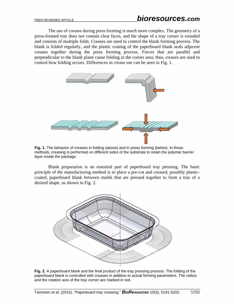
The use of creases during press forming is much more complex. The geometry of a
press-formed tray does not contain clear faces, and the shape of a tray corner is rounded
and consists of multiple folds. Creases are used to control the blank forming process. The
blank is folded regularly, and the plastic coating of the paperboard blank seals adjacent
creases together during the press forming process. Forces that are parallel and
perpendicular to the blank plane cause folding in the corner area; thus, creases are used to
control how folding occurs. Differences in crease use can be seen in Fig. 1.
Fig. 1. The behavior of creases in folding (above) and in press forming (below). In these methods, creasing is performed on different sides of the substrate to retain the polymer barrier layer inside the package.
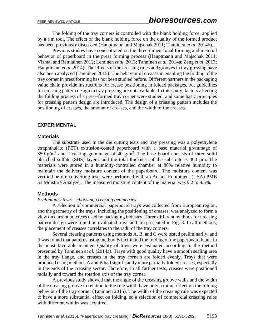
Blank preparation is an essential part of paperboard tray pressing. The basic
principle of the manufacturing method is to place a pre-cut and creased, possibly plastic-
coated, paperboard blank between molds that are pressed together to form a tray of a
desired shape, as shown in Fig. 2.
Fig. 2. A paperboard blank and the final product of the tray pressing process. The folding of the paperboard blank is controlled with creases in addition to actual forming parameters. The radius and the rotation axis of the tray corner are marked in red.
PEER-REVIEWED ARTICLE bioresources.com
Tanninen et al. (2015). “Paperboard tray creasing,” BioResources 10(3), 5191-5202. 5193
The folding of the tray corners is controlled with the blank holding force, applied
by a rim tool. The effect of the blank holding force on the quality of the formed product
has been previously discussed (Hauptmann and Majschak 2011; Tanninen et al. 2014b).
Previous studies have concentrated on the three-dimensional forming and material
behavior of paperboard in the press forming process (Hauptmann and Majschak 2011;
Vishtal and Retulainen 2012; Leminen et al. 2013; Tanninen et al. 2014a; Zeng et al. 2013;
Hauptmann et al. 2014). The effects of the creasing rules and grooves in tray pressing have
also been analyzed (Tanninen 2015). The behavior of creases in enabling the folding of the
tray corner in press forming has not been studied before. Different partners in the packaging
value chain provide instructions for crease positioning in folded packages, but guidelines
for creasing pattern design in tray pressing are not available. In this study, factors affecting
the folding process of a press-formed tray corner were studied, and some basic principles
for creasing pattern design are introduced. The design of a creasing pattern includes the
positioning of creases, the amount of creases, and the width of the creases.
EXPERIMENTAL
Materials The substrate used in the die cutting tests and tray pressing was a polyethylene
terephthalate (PET) extrusion-coated paperboard with a base material grammage of
350 g/m2 and a coating grammage of 40 g/m2. The base board consists of three solid
bleached sulfate (SBS) layers, and the total thickness of the substrate is 460 µm. The
materials were stored in a humidity-controlled chamber at 80% relative humidity to
maintain the delivery moisture content of the paperboard. The moisture content was
verified before converting tests were performed with an Adams Equipment (USA) PMB
53 Moisture Analyzer. The measured moisture content of the material was 9.2 to 9.5%.
Methods Preliminary tests – choosing creasing geometries
A selection of commercial paperboard trays was collected from European region,
and the geometry of the trays, including the positioning of creases, was analyzed to form a
view on current practices used by packaging industry. Three different methods for creasing
pattern design were found on evaluated trays and are presented in Fig. 3. In all methods,
the placement of creases correlates to the radii of the tray corners.
Several creasing patterns using methods A, B, and C were tested preliminarily, and
it was found that patterns using method B facilitated the folding of the paperboard blank in
the most favorable manner. Quality of trays were evaluated according to the method
presented by Tanninen et al. (2014a). Trays with good quality have a smooth sealing area
in the tray flange, and creases in the tray corners are folded evenly. Trays that were
produced using methods A and B had significantly more partially folded creases, especially
in the ends of the creasing sector. Therefore, in all further tests, creases were positioned
radially and toward the rotation axis of the tray corner.
A previous study showed that the angle of the creasing groove walls and the width
of the creasing groove in relation to the rule width have only a minor effect on the folding
behavior of the tray corner (Tanninen 2015). The width of the creasing rule was expected
to have a more substantial effect on folding, so a selection of commercial creasing rules
with different widths was acquired.

PEER-REVIEWED ARTICLE bioresources.com
Tanninen et al. (2015). “Paperboard tray creasing,” BioResources 10(3), 5191-5202. 5194
Fig. 3. Creasing pattern designs. A) Creases are positioned in a 45° angle parallel to each other; B) creases are positioned radially toward the rotation axis of the tray corner; C) creases are positioned radially toward a point deviating 10 to 30 mm from the rotation axis of the tray corner.
Paperboard manufacturers recommend the use of creasing rules with widths of 0.71
mm (2 pt.) for testing a substrate’s thickness. Also, rules with widths of 0.40 mm (1.1 pt.),
1.05 mm (3 pt.), and 1.42 mm (4 pt.) were tested. The purpose of these tests was to study
how material compaction and folding occurred in the tray corner area when the width of
the creases was altered to determine if a single, wider crease could compact more material.
The main dimensions of the creasing rule and groove are presented in Fig. 4.
Fig. 4. The main dimensions of the creasing rule and groove
PEER-REVIEWED ARTICLE bioresources.com
Tanninen et al. (2015). “Paperboard tray creasing,” BioResources 10(3), 5191-5202. 5195
Groove widths were calculated to fit corresponding creasing rules using the
following formula,
WCG = µ TPB + WCR (1)
where WCG is the creasing groove width, µ is the creasing coefficient, TPB is the thickness
of paperboard, and WCR is the creasing rule width.
The creasing coefficient, which defines the creasing groove width in relation to the
substrate thickness, is normally between 1.2 and 1.7, depending on the application. The
behavior of the creases in tray pressing was found in a previous study to be most desirable
with the value of 1.4 (Tanninen 2015). Smaller values result in creasing grooves that are
too narrow and the die cutting process becomes too fierce for the paperboard to withstand.
The surface of the paperboard fractures at the tops of the creases. Larger values make the
grooves too wide and the shape of the crease too round.
Rectangular trays (265 x 162 x 38 mm) were press-formed using a similar creasing
pattern with all crease widths. Process parameters were kept constant in press forming
phase of the die-cut blanks (blank holding force 1.20 kN, female mould temperature 170°C,
male mould temperature 50 °C, pressing force 135 kN and pressing speed 130 mm/s). The
tray wall area was visually estimated to be smoother, with narrower creases, but a more
noticeable difference was found in the tray flange, an area on which lidding film sealing is
performed. The folding in some of the creases was uneven and one-sided, which makes
successful lid-sealing impossible.
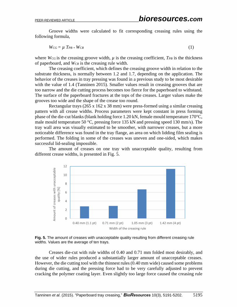
The amount of creases on one tray with unacceptable quality, resulting from
different crease widths, is presented in Fig. 5.
Fig. 5. The amount of creases with unacceptable quality resulting from different creasing rule widths. Values are the average of ten trays.
Creases die-cut with rule widths of 0.40 and 0.71 mm folded most desirably, and
the use of wider rules produced a substantially larger amount of unacceptable creases.
However, the die cutting tool with the thinnest rules (0.40 mm wide) caused some problems
during die cutting, and the pressing force had to be very carefully adjusted to prevent
cracking the polymer coating layer. Even slightly too large force caused the creasing rule
0
2
4
6
8
10
12
0.40 mm (1.1 pt) 0.71 mm (2 pt) 1.05 mm (3 pt) 1.42 mm (4 pt)
Am
ou
nt
of
crea
ses
wit
h u
nac
cep
tab
le
qu
alit
y [%
]
Width of the creasing rule

PEER-REVIEWED ARTICLE bioresources.com
Tanninen et al. (2015). “Paperboard tray creasing,” BioResources 10(3), 5191-5202. 5196
to cut through the polymer coating layer. Tools with wider creasing rules did not cause the
same issues.
Based on the results of the preliminary tests, 0.71-mm-wide creasing rules were
chosen for use in the subsequent tests.
The compilation of creasing patterns
An array of industrial-scale press-forming tool sets was selected with the basic
shape of the tray corner in mind. Tool sets enabled the production of trays representing
four different rectangular designs and one oval-shaped design. Even though the main
dimensions of the trays varied, the main focus was on the dimensions related to the tray
corner area: the depth of the tray and the corner radii.
Creases were positioned uniformly to the corner area of the tray blank and radially
toward the rotation axis of the tray corner. The composition and essential dimensions of
the creasing pattern design are shown in Fig. 6.
Fig. 6. The composition and essential dimensions of creasing
The distance between adjacent creasing grooves was changed within the range of
0.5 to 3.0 mm. The respective amounts of creases, calculated on basis of distance values,
are listed in Table 1 along with the dimensions of the trays produced. The depths of the
trays enabled the use of two sets of creases with different lengths in the corner area.
(Cdmin)

PEER-REVIEWED ARTICLE bioresources.com
Tanninen et al. (2015). “Paperboard tray creasing,” BioResources 10(3), 5191-5202. 5197
Table 1. Test Tray Specifications
Tray 1 Rect-
angular
Tray 2 Rect-
angular
Tray 3 Rect-
angular
Tray 4 Rect-
angular Tray 5 Oval
Height of the Tray (mm) 50 35 38 56 45
Length of the Tray (mm) 209 209 265 326 219
Width of the Tray (mm) 139 139 162 261 130
Radius of Tray Corner (mm) 37 40 40 75,5 65
Length of the Blank (mm) 288 260 319 400 286
Width of the Blank (mm) 219 190 216 334 199.5
Radius of the Blank Corner (mm) 77 62 70 110 99,25
r1 (mm) 20 20 19 37 48
Distance between adjacent Creasing Grooves/Cdmin
(mm)
Total Number of Creases
Total Number of Creases
Total Number of Creases
Total Number of Creases
Total Number of Creases
0.5 164 164 157 279 177
1 135 135 129 226 142
1.5 116 116 112 191 120
2 103 103 99 167 104
2.5 93 93 90 149 92
3 86 86 83 135 83
The press forming process parameters were optimized for each mold set and
paperboard combination to achieve trays with good quality. Differences in the size of the
trays were compensated for by adjusting the blank holding force (Trays 1 and 2 0.81 kN,
Tray 3 1.20 kN, Tray 4 2.38 kN and Tray 5 0.79 kN). Other parameters were kept constant
during the trial runs: female mould temperature 170 °C, male mould temperature 50 °C,
pressing force 135 kN and pressing speed 130 mm/s.
The changes made to the creasing pattern primarily affected the amount of unclosed
creases in the flange of the tray. Trays were also press-formed using a higher blank holding
force, which caused fractures in the tray corners. Altering the creasing pattern had no
noticeable effect on the amount or length of the fractures.
RESULTS AND DISCUSSION
The effect of the creasing pattern and the quality of crease formation were
evaluated with the same methods as in previous research (Leminen 2013): by observing
the quality of folding and the flatness of the tray flange. Discarded creases were not formed
properly, and the corresponding folds had large gaps in the tray flange area, which make
tight lidding of the tray impossible. A pair of discarded creases is marked in Fig. 7.
The amount of creases with unacceptable quality resulting from different creasing
patterns is shown in Fig. 8.

PEER-REVIEWED ARTICLE bioresources.com
Tanninen et al. (2015). “Paperboard tray creasing,” BioResources 10(3), 5191-5202. 5198
Fig. 7. Discarded creases in the tray flange. Creases have not been formed adequately leaving a gap between flat areas surrounding the crease.
Fig. 8. Functionality of creases in test trays
In trays with the smallest blank corner radius (trays 1, 2, and 3), a greater distance
between adjacent creases was correlated with an increased amount of discarded creases.
The substrate folded more evenly and the wall of the tray was smoother when the material
had more possibilities (folds) to compact during the press forming phase. However, when
the distance between the adjacent creases was 0.5 mm, the durability of the thin land
between the creasing grooves was a cause for concern, especially when a plastic matrix
was used. Therefore, the minimum distance between creases should be limited to 1.0 mm.
In trays 1, 2, and 3, the amount of creases was as high as possible in the tray corner within
the limitations of the creasing rule and groove dimensions discussed earlier. Tray 2 could
not be produced without unacceptable creases, which indicates that the clearance between
50
100
150
200
250
300
Nu
mb
er o
f cr
ease
s
Distance between adjacent creasing grooves [mm]
Unacceptable creases
Acceptable creases
Tray 1 Tray 4Tray 3Tray 2 Tray 5

PEER-REVIEWED ARTICLE bioresources.com
Tanninen et al. (2015). “Paperboard tray creasing,” BioResources 10(3), 5191-5202. 5199
the male and female mould was not correct everywhere and that the mold set needed
modification. Trays 4 and 5, which had larger blank corner radii, were more successful
when a larger distance between adjacent creases was used. Smoothness of the tray walls
was considered best when the greatest amount of creases was used for all the trays. The
following formulas were established on the basis of the trial runs.
The minimum distance between adjacent creases (from the center line of one rule
to another) was defined as,
Cdmin = WCG + WML (2)
where WML is width of the land between adjacent creasing grooves. WML is 1 mm when the
radius of the blank corner is below 80 mm. WML is 2 mm when the radius of the blank
corner is 80 to 110 mm. Further testing with different mold sets should be performed to
make the recommended values more accurate. Also testing of other types of paperboard in
further studies is advisable.
The quantity of creases in first set (90° tray corner) is defined as
Qc1= min
1
min
1
2
4/)2(
dd C
r
C
r
(3)
Sets of shorter creases should be placed regularly between longer creases.
The angle between adjacent creases in the first set is defined as
Ac1= 1
90
cQ
(4)
Finally, the radius of the second crease set is
r2 = 2r1 (5)
Additional creases should be placed on each side of the corner creases to avoid
wrinkles (folds that are not assisted by creases) in the walls of the tray. These creases are
placed perpendicular to the sides of the blank and are full-length. The distance between
creases can be calculated with Eq. 2. The amount of additional creases was optimized to 3
to 4 for tested tray designs, depending on the tray shape.
Results from trial runs were analyzed and supplemented with observations made
from commercial tray samples to facilitate the creasing pattern design process.
Relationships between the presented formulas and features of the tray were also evaluated.
Morphological charts were developed as a tool for designers to determine the relationships
between the functional and structural aspects of in multi-dimensional, non-quantifiable
design problem tasks. Morphology provides a structure for an overview of the considered
functions and aspects and their alternative solutions. The functions and aspects are derived
from the demands and wishes of the designer and define the functional requirements of the
product. The tool itself is a simple table or matrix in which the possible solution principles
for each function or aspect are listed. Different overall solutions are created by combining

PEER-REVIEWED ARTICLE bioresources.com
Tanninen et al. (2015). “Paperboard tray creasing,” BioResources 10(3), 5191-5202. 5200
various solution principles to form a complete combination to find a solution for the design
task (Zeiler and Savanovic 2010).
Table 2. Morphological Analysis of the Creasing Pattern Alternatives
1st Crease Set
2nd (and 3rd, etc.) Crease
Set
Additional and
Assisting Creases
Formability in Tray Forming Process
Ou
ter
Dim
en
sio
ns
of
the
Tra
y Length Larger length
provides room for additional
creases
Small influence
Width Larger width provides room for additional
creases
Small influence
Height Affects length of creases
Affects length of creases. If height is
small, 2nd set aren’t required
Very large influence. Deeper the tray, harder to form.
Fe
atu
res
of
the
Tra
y
Steepness of the Tray
Wall (Eq 5)
Affects length and number of
creases
Affects length and number of
creases
Affects length of creases
Very large influence. Steeper the tray wall,
harder to form.
Main Radius of the Tray
Corner (Eq 3-5)
Affects number of creases
Affects number of creases
Very large influence. Larger the corner
radius, easier to form.
Radii of the Bottom
Corner of the Tray (Eq 3-5)
Affects number of creases
Affects length and number of
creases
Average influence. Small radiuses
demand more from material properties.
Thickness of the Paperboard
(Eq 1-5)
Affects number of
creases and distance between creases
Affects number of
creases and distance between creases
Affects distance between creases
Average influence. Thicker paperboard has usually better
strength properties in forming.
Shape of the Tray (Eq 3-5)
Affects positioning of
creases
Affects positioning of
creases
Affects positioning of
creases
Very large influence. Round and oval
shaped trays easiest to form. Complex shapes can be
impossible to form.
Morphological chart analysis can be regarded as a formal design tool enabling
collaborative product development. It is widely accepted in textbooks and by practitioners
as an effective technique for the conceptual design of products, processes, and systems.
This type of analysis has been developed during the past decades, and Huang and Mak
(1999) discuss the use of Web technology in the implementation of morphological chart
analysis. The results of Huan and Mak’s study showed that the incorporation of various
decision-making activities of concept design into one integrated Web-based system allows

PEER-REVIEWED ARTICLE bioresources.com
Tanninen et al. (2015). “Paperboard tray creasing,” BioResources 10(3), 5191-5202. 5201
the designer to choose the most appropriate idea from numerous potential alternatives in
an objective, systematic way. Weber and Condoor (1998) stated that the morphological
matrix is a key methodology that can improve the effectiveness of the concept generation
phase of the design process. However, as discussed in Weber and Condoor’s paper,
identifying independent design functions and determining the synergistic compatibility of
combining alternative solutions is difficult. In this study, morphological chart analysis was
utilized to determine the most reasonable combination of creases to design the optimal
creasing pattern.
CONCLUSIONS
1. It is possible to produce press-formed paperboard trays that fulfill all of the required
functional and visual properties when the creasing pattern is designed according to
recommendations presented in this study.
2. The amount of creases in the tray corner is the most important variable in the pattern
design when the trays are produced by press forming.
3. The substrate folds more evenly and the wall of the tray is smoother when the material
has a greater amount of folds to compact during the press forming process.
4. The correct amount of creases can be determined on the basis of the radius of the blank
corner using formulas presented in this study.
5. The outcome of this study is a morphological analysis of the creasing pattern
alternatives and a selection of equations that can be used during the creasing pattern
design process.
6. Wider creases cannot be utilized to compact material in tray corners. Creases die cut
with narrower rule widths folded the most desirably, and the use of wider rules
produced a substantially greater amount of discarded creases.
7. This study also indicates that creases positioned radially toward the rotation axis of the
tray corner assist the folding of the paperboard blank most suitably.
REFERENCES CITED
Hauptmann, M., and Majschak, J. (2011). “New quality level of packaging components
from paperboard through technology improvement in 3D forming,” Packaging
Technology and Science 24(7), 419-432. DOI: 10.1002/pts.941
Hauptmann, M., Ehlert, S. and Majschak, J. (2014). “The effect of concave base shape
elements on the three dimensional forming process of advanced paperboard
structures,” Packaging Technology and Science 27(12), 975-986. DOI:
10.1002/pts.2089
Huang, G. Q., and Mak, K. L. (1999). “Web-based morphological charts for concept
design in collaborative product development,” Journal of Intelligent Manufacturing
10(3-4), 267-278. DOI: 10.1023/A:1008999908120
PEER-REVIEWED ARTICLE bioresources.com
Tanninen et al. (2015). “Paperboard tray creasing,” BioResources 10(3), 5191-5202. 5202
Joukio, R., and Mansikkamäki, S. (1998). “Cartonboard package manufacturing and
applications, paper and paperboard converting,” TAPPI Papermaking Science and
Technology Book Series, Book 12, pp. 231.
Kirwan, M. J. (2005). Handbook of Paper and Paperboard Packaging Technology,
Blackwell Publishing, UK.
Leminen, V., Tanninen, P., Mäkelä, P., and Varis, J. (2013). “Combined effect of
paperboard thickness and mould clearance in the press forming process,”
BioResources 8(4), 5701-5714. DOI: 10.15376/biores.8.4. 5701-5714
Tanninen, P., Kasurinen, M., Eskelinen, H., Varis, J., Lindell, H., Leminen, V.,
Matthews, S., and Kainusalmi, M. (2014a). “The effect of tool heating arrangement
on fibre material forming,” Journal of Materials Processing Technology 214(8),
1576-1582. DOI: 10.1016/j.jmatprotec.2014.03.001
Tanninen, P., Lindell, H., Saukkonen, E., and Backfolk, K. (2014b). “Thermal and
mechanical durability of starch-based dual polymer coatings in the press forming of
paperboard,” Packaging Technology and Science 27(5), 353-363. DOI:
10.1002/pts.2036
Tanninen, P., Saukkonen, E., Leminen, V., Lindell, H., and Backfolk, K. (2015).
“Adjustment of the die cutting process and tools for biopolymer dispersion coated
paperboards,” Nordic Pulp & Paper Research Journal (in press).
Vishtal, A., and Retulainen, E. (2012). “Deep-drawing of paper and paperboard: The role
of material properties,” BioResources 7(3), 4424-4450. DOI:
10.15376/biores.7.3.4424-4450
Weber, R., and Condoor, S. (1998). “Conceptual design using a synergistically
compatible morphological matrix,” Frontiers in Education Conference, FIE '98, 28th
Annual Conference, 4 to 7 November, CT, USA, Volume 1, pp. 171-176.
Zeiler, W., and Savanovic, P. (2010). “Integral design workshops: Organization, structure
and testing,” Journal of Systemics, Cybernetics and Informatics 8(4), 30-41.
Zeng, X., Vishtal, A., Retulainen, E., Sivonen, E., and Fu, S. (2013). “The elongation
potential of paper - How should fibres be deformed to make paper extensible?,”
BioResources 8(1), 472-486. DOI: 10.15376/biores.8.1.472-486
Article submitted: March 13, 2015; Peer review completed: May 15, 2015; Revised
version received and accepted: June 26, 2015; Published: July 2, 2015.
DOI: 10.15376/biores.10.3.5191-5202