pedestrian bridges: structural design by masters of architecture … · pedestrian bridges -...
TRANSCRIPT

AC 2011-1101: PEDESTRIAN BRIDGES - STRUCTURAL DESIGN BYMASTERS OF ARCHITECTURE STUDENTS
Sinead MacNamara, Syracuse University
c©American Society for Engineering Education, 2011
Page 22.1145.1
PEDESTRIAN BRIDGES - STRUCTURAL DESIGN BY MASTERS OF ARCHITECTURE STUDENTS
Introduction Pedestrian Bridges all over the world offer an aesthetically creative and technically innovative array of structures for student study. Such bridges (especially in cities) are highly visible to the tourist and the citizen alike. Bridges reveal and exhibit their structural form much more clearly than most buildings do, and this makes them ideal teaching tools. Furthermore, the AASHTO Guide Specifications for Design of Pedestrian Bridges represent a manageable introduction to formal engineering design for a semester long project. This paper describes a one credit hour, semester long, project undertaken by MArch students alongside a required course in Structural Engineering Design. Students undertook conceptual design of pedestrian bridges. After a class wide study of innovative precedents, they worked in small groups and were required to choose and analyze a site, and propose an initial structural scheme. A minimum clear span was required to push more ambitious spanning strategies. They then performed a Finite Element Analysis and sized all the primary structural members of the bridge. The results of the project were exhibited to a jury of engineering and architecture professors, with students required to defend both their structural and aesthetic decisions in the design process. The results of the project were very successful. The jury found the design to be of a high standard both technically and architecturally. Students reported that having autonomy over a whole design from start to finish both increases enthusiasm and helps students begin to understand the variables that influence the form and the scale of engineering solutions. Background Engineering education researchers and practitioners have widely acknowledged the problem of design education, in engineering programs. Previous studies of engineering student design processes report a significant difference between the capacity of student engineers and engineering practitioners in “problem scoping” and “information gathering” at the start of a design project, and argue that engineering students would benefit from teaching methods designed to model that process for them.1 In the 1990s first-year design courses were widely introduced in engineering programs in an attempt to introduce students to the nature of their chosen profession earlier in their college careers.2 Dym et al identify a host of institutions (Harvey Mudd, Purdue, Northwestern, Penn State, Colorado School of the Mines, University of Alabama, Columbia, Cooper Union, Drexel, NJIT, Ohio State, Polytechnic South Carolina, USC, Carnegie Mellon, University of Colorado at Boulder, Georgia Tech) that introduced design thinking through project-based learning in their first year programs.3 Most of these schools reported a positive impact on retention for those students who had taken some form of first year “cornerstone” engineering design course. Dym et al further argue that such courses have a positive impact on student interest and performance in later engineering courses. Capstone design courses at the end of engineering programs likewise represent an opportunity for students to take both design work and a whole real world structure. In
Page 22.1145.2
their other courses however the common engineering teaching paradigm divides complex problems into many pieces which students are then taught to solve independently, all the while anticipating that eventually, they will:
“ be able to develop a solution by combining them,…..,Eventually, …..,the effort involved in learning about the small pieces is so overwhelming that we can longer synthesize the original problem–the parts become more important than the whole.”4
The project outlined here represents one model as to how both holistic engineering design might be inserted alongside a more traditional course, in more depth than is possible in the first semester and at an earlier point than the last semester of a student’s education. Architecture programs, by contrast, spend little time on the finer mathematical details that engineering students must master. There are generally two or three required semesters of structures courses, which aim to equip architecture students to understand the variables that influence the form and the scale of engineering solutions. But in this author’s experience, even in the comprehensive studio, there is little requirement that students apply the principles they have learned in structures class to their design assignments. For architecture programs, the project discussed here provides a model for how students can engage structural engineering at a useful level (although by no means at the level of final resolution of member size or consideration of all secondary structural effects). A project like this one is a useful tool to help students see the how an understanding of the most basic structural principles allows for more control and precision in the design process, which similarly allows for a richer and more finely detailed representation of their design work. This project undertaken by masters of architecture students, none of whom had an undergraduate degree in architecture were in the second semester of the two required semesters of structures in their program, who might reasonably approximate freshman and sophomore engineering students in terms of technical skills. I argue that the success of this project points to the applicability of pedestrian bridge design (and indeed structural design more generally) at various levels of both architecture and engineering education. The Project There were 18 graduate students taking a 4-credit structures course. Three of these credits were taken up by the lecture course shared with a further 120 undergraduate students. The final credit hour represented a chance to work more closely with the instructor and to take on more challenging work as befits a graduate level course. The group met for an hour every week with the instructor for the purposes of this project. The design work was split into 5 assignments, the first of which was Precedent Analysis. Looking at peer structures similar in scope or scale to the one you intend to design is a common pedagogical tool in architecture. It is less often seen in an engineering context
Page 22.1145.3
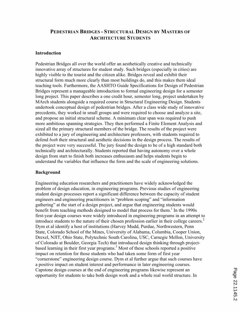
but it can be very useful, especially in establishing rules of thumb for the scale of certain structural solutions (eg length/depth for a suspension bridge). After a presentation introducing some historical and contemporary examples of innovative structural design in pedestrian bridges such as Robert Maillart’s Toss River Bridge (a deck stiffened arch in concrete), and Schlaich Bergermann and Partner’s Liberty Bridge in Greenville South Carolina (a cable stayed bridge with a curved deck and inclined pylons), the students were required to find a bridge they liked and compile a report. The report included information about the site (location, context, views of and from the bridge), the architectural intent, and the structure itself. The presentations included an original analysis explaining the structural form of the bridge, how it worked and how the structural form was/was not visible. Dimensions of the structure: span, height, and cross section of primary structural members (e.g. depth of deck, area of cables, truss element dimensions etc) were also included. Students were required to produce written report and a digital presentation, images from some of the digital presentations are in Figures 1, 2, and 3. A collection of hard copies of these reports was made available to all of the students as source material as the project progressed.
FIGURE 1
IMAGES FROM PRECEDENT ANALYSIS ASSIGNMENT
Page 22.1145.4

FIGURE 2
IMAGES FROM PRECEDENT ANALYSIS ASSIGNMENT
FIGURE 3
IMAGES FROM PRECEDENT ANALYSIS ASSIGNMENT
Page 22.1145.5

The second assignment was site analysis. In engineering courses all too often the context of a problem right down to the boundary conditions is given to students. In this assignment the students had to pick a site and figure out the constraints and conditions it presented by themselves. At this point the students formed into six groups of three. Most groups chose a site they had some familiarity with, either from their hometowns, a city they had visited, or a site they had used in a previous design studio project. The report created included: a plan of the site in its location, drawn to scale with dimensions, showing the context of the site (approx 500 ft in every direction, buildings, streets, pedestrian circulation, landscape features as appropriate); a closer scale map of the site showing the proposed trajectory of the bridge and how it connected with the immediately adjacent built fabric or landscape; plan drawings that analyzed the site in terms of major axes in the built fabric or landscape, automotive or pedestrian circulation, proximity to public transport, significant adjacencies, or other appropriate features; a section through the site – along the axis of the proposed bridge; photographs and drawings of the site and its context. Some images from the site analysis project are in Figures 4 and 5.
FIGURE 4
IMAGE FROM SITE ANALYSIS ASSIGNMENT
FIGURE 5
IMAGES FROM SITE ANALYSIS ASSIGNMENT
Page 22.1145.6
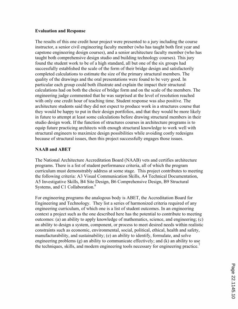
The third assignment was schematic design. The students were instructed to use the AASHTO 2009 code to establish the live load and appropriate load combinations for which their bridge must be designed.5 Precedent studies and estimates based on material choice were used to approximate dead load. From the site analysis students already knew the major dimensions for the bridge (main spans, side spans if any, clearance (as applicable), width of deck. They then chose a form for the bridge (arch, suspension, cable stayed etc). They complied a report including: their load calculations; a description of the form of the bridge, a “defense” of the structural form (site, context, technical demands of the span, exposure to weather, marine environment etc; the analysis of the form determining the forces in the primary structural members as a result of the gravity loads applied. The calculations required for this analysis (arch, suspension cables, cable stays, and beams) had been covered in the first structures course. Emphasizing the iterative nature of engineering design, they were encouraged to set up an excel spreadsheet for these calculations so that changes could be made quickly as the design evolved. The fourth assignment was a FEM analysis of the bridges using SAP2000. None of the students had used this (or any structural analysis software) before, and so were first given a customized tutorial with instructions in excruciating detail showing them how to: build a two dimensional beam bridge; apply loads; establish boundary conditions; run the analysis; and extract the deformed shape, the axial forces, and the shear and bending diagrams. Each group met with the instructor in the computer lab when building and testing their models so as to maximize the efficiency of this process. Once each group had established the maximum axial, shear and bending in the primary structural members of the bridge they were ready for the final design assignment. At this point in the lecture course (two thirds of the way through the second semester of structures) they had received instruction on how to size a steel or concrete beam under a known bending moment, a cable with known axial force, and now to approximate the tension and compression in a truss, and size compression member in steel. Once they had completed the appropriate calculations for their bridge they were able to check their assumptions about dead load and run the analysis again if necessary. At this stage a number of groups had to reassess the dimensions of the primary members and in one case reconfigure the form. The final presentations of the projects included rendered images (to scale, with pedestrians etc). These images had to use the dimensions that the calculations had called for. This was a key part of the project and was intended to help the architecture students see how much control over the representation process they can gain when they bring their structural knowledge to bear on an assignment. Selected images from the final presentations (including some structural analysis) are shown in Figures 6-9.
Page 22.1145.7
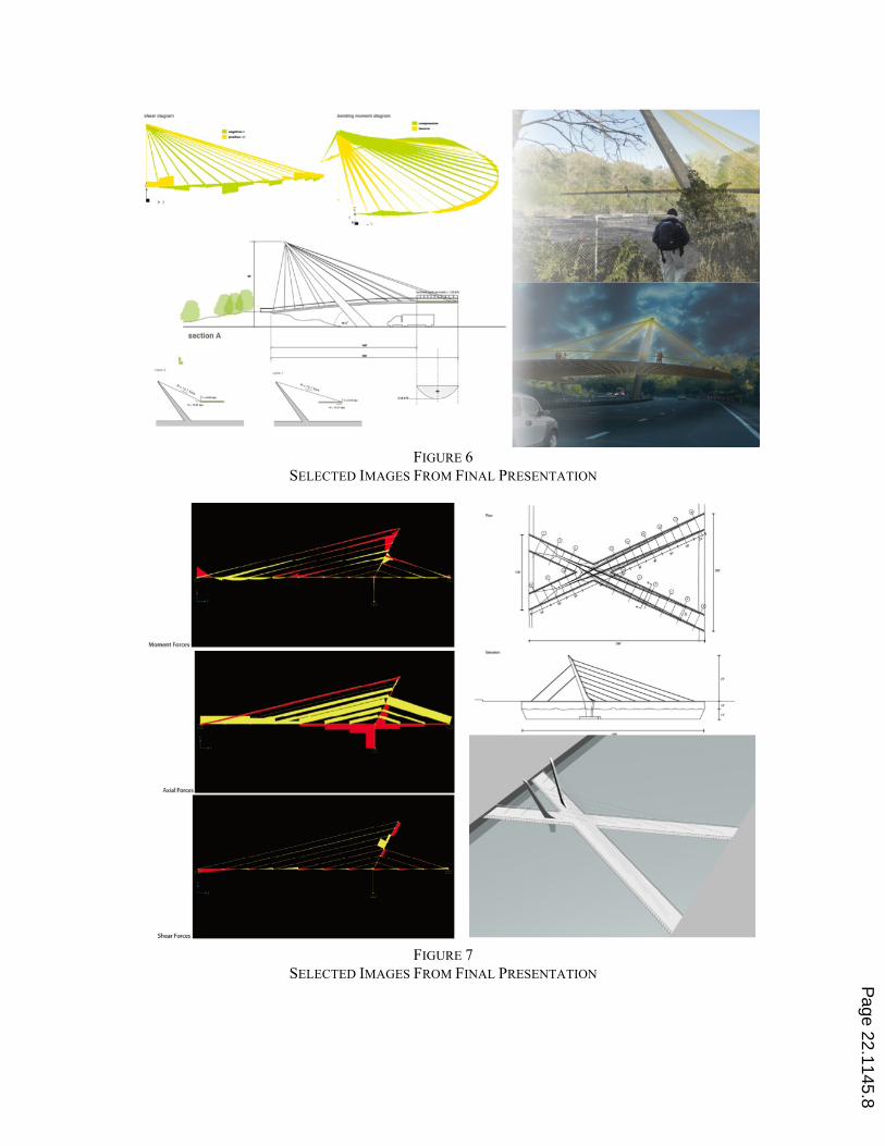
FIGURE 6
SELECTED IMAGES FROM FINAL PRESENTATION
FIGURE 7
SELECTED IMAGES FROM FINAL PRESENTATION P
age 22.1145.8
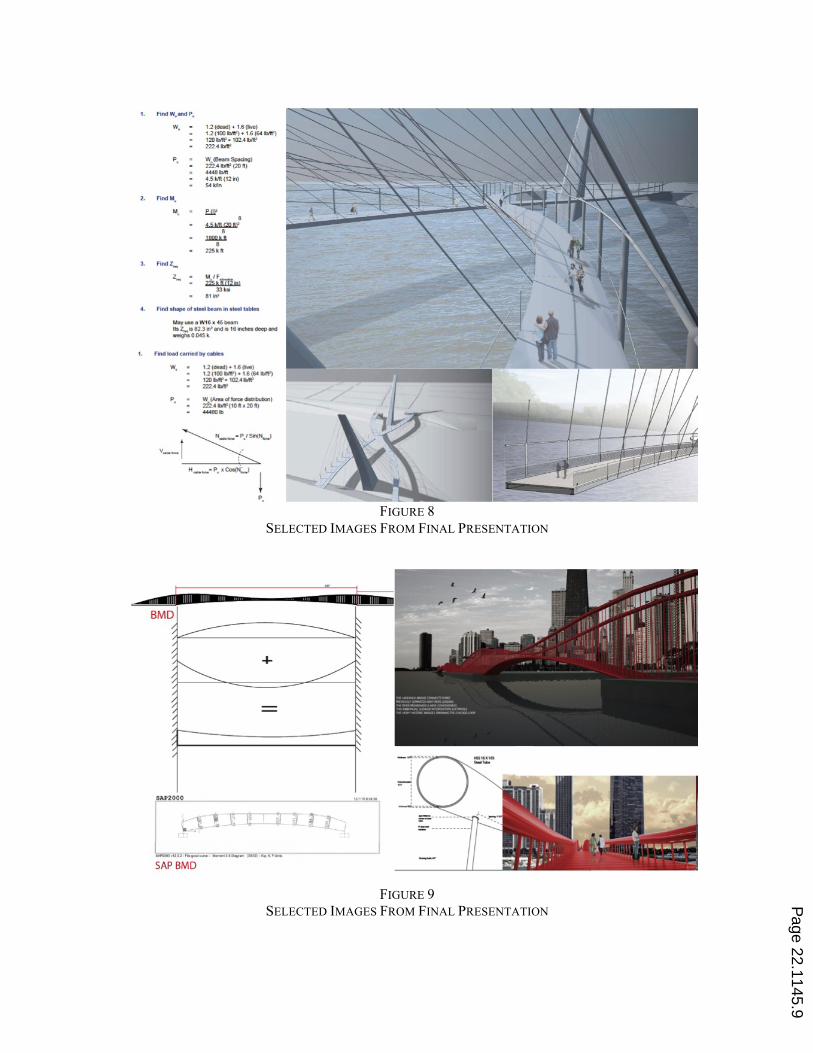
FIGURE 8
SELECTED IMAGES FROM FINAL PRESENTATION
FIGURE 9
SELECTED IMAGES FROM FINAL PRESENTATION
Page 22.1145.9
Evaluation and Response The results of this one credit hour project were presented to a jury including the course instructor, a senior civil engineering faculty member (who has taught both first year and capstone engineering design courses), and a senior architecture faculty member (who has taught both comprehensive design studio and building technology courses). This jury found the student work to be of a high standard, all but one of the six groups had successfully established the scale of the form of their bridge design and satisfactorily completed calculations to estimate the size of the primary structural members. The quality of the drawings and the oral presentations were found to be very good. In particular each group could both illustrate and explain the impact their structural calculations had on both the choice of bridge form and on the scale of the members. The engineering judge commented that he was surprised at the level of resolution reached with only one credit hour of teaching time. Student response was also positive. The architecture students said they did not expect to produce work in a structures course that they would be happy to put in their design portfolios, and that they would be more likely in future to attempt at least some calculations before drawing structural members in their studio design work. If the function of structures courses in architecture programs is to equip future practicing architects with enough structural knowledge to work well with structural engineers to maximize design possibilities while avoiding costly redesigns because of structural issues, then this project successfully engages those issues. NAAB and ABET The National Architecture Accreditation Board (NAAB) vets and certifies architecture programs. There is a list of student performance criteria, all of which the program curriculum must demonstrably address at some stage. This project contributes to meeting the following criteria: A3 Visual Communication Skills, A4 Technical Documentation, A5 Investigative Skills, B4 Site Design, B6 Comprehensive Design, B9 Structural Systems, and C1 Collaboration.6 For engineering programs the analogous body is ABET, the Accreditation Board for Engineering and Technology. They list a series of harmonized criteria required of any engineering curriculum, of which one is a list of student outcomes. In an engineering context a project such as the one described here has the potential to contribute to meeting outcomes: (a) an ability to apply knowledge of mathematics, science, and engineering; (c) an ability to design a system, component, or process to meet desired needs within realistic constraints such as economic, environmental, social, political, ethical, health and safety, manufacturability, and sustainability; (e) an ability to identify, formulate, and solve engineering problems (g) an ability to communicate effectively; and (k) an ability to use the techniques, skills, and modern engineering tools necessary for engineering practice.7
Page 22.1145.10

Conclusions This project was designed to run alongside a traditional lecture course and to demonstrate that it is possible for students to engage in full-scale design of structures at multiple levels in their education, with relatively limited time and previous knowledge. In that respect it has succeeded. Pedestrian Bridges make an especially useful example because of the (relative) lack of complexity in the code requirements and because of the structural expression they provide. This model has rich potential for both architecture and engineering programs. Further work is planned, the author will attempt to introduce a modified version of the project alongside a statics course for sophomore engineering students.
1 Atman, C. J. Adams, R. S. Cardella, M. E. Turns, J. Mosborg, S. Saleem, J. 2007 Engineering Design Processes: A Comparison of Students and Expert Practitioners. Journal of Engineering Education, 96(4) pg. 359 2 Dally, J. W. , and Zhand, G. M. 1994. A Freshman Engineering Design Course. Journal of Engineering Education 83(2) pp 83-9. 3 Dym, C.L. Agogino, A. M. . Eris, O. Frey, D. D. Leifer, L. J. 2005 Engineering Design Thinking, Teaching, and Learning Journal of Engineering Education. 94(1) pp 103-120 4 Katehi, L. 2005. The Global Engineer. Educating the Engineer of 2020: Adapting Engineering Education to the New Century. National Academy of Sciences, 4 5 American Association of State Highway Transportation Officials, AASHTO. 2009. LRFD Guide Specifications for Design of Pedestrian Bridges, 2nd Ed. 6National Architectural Accrediting Board, Inc. 2009. 2009 Conditions for Accreditation. NAAB, Washington DC. pp 22-24. 7ABET Engineering Accreditation Commission. 2009. Criteria for Accrediting Engineering Programs. ABET, Inc. Baltimore, MD.
Page 22.1145.11