pedal - shimano · pd-9000 pd-6800 pd-5800 pd-5700-c pd-r550 pd-r540-la pd-m9000 pd-m9020 pd-m8000...
TRANSCRIPT
(English) DM-PD0002-07
Dealer's Manual
PD-9000 PD-6800 PD-5800
PD-5700-C PD-R550
PD-R540-LA
PD-M9000 PD-M9020 PD-M8000 PD-M8020
PD-M990 PD-M995
PD-T700 PD-T420 PD-T400
PD-MT50
Pedal
2
CONTENTS
IMPORTANT NOTICE ............................................................................................................................. 3
TO ENSURE SAFETY ............................................................................................................................. 4
LIST OF TOOLS TO BE USED ................................................................................................................. 7
INSTALLATION ...................................................................................................................................... 9
SPD-SL pedals (PD-9000/PD-6800/PD-5800/PD-5700-C/PD-R550/PD-R540-LA) ............................................. 9 Cleat types ................................................................................................................................................................................... 9 Attaching the cleats .................................................................................................................................................................. 10 When using the SM-SH20 cleat spacer (not included) ............................................................................................................ 11 Adjusting cleat position ........................................................................................................................................................... 12 Mounting the pedals on the crank arms ................................................................................................................................. 13
SPD pedals/Click’R (Single release mode cleats: SM-SH51/Multiple release mode cleats: SM-SH56) ....... 14 Cleat types ................................................................................................................................................................................. 14 Attaching the cleats .................................................................................................................................................................. 14 When using cleat spacers ......................................................................................................................................................... 16 Adjusting cleat position ........................................................................................................................................................... 17 Waterproof seal ........................................................................................................................................................................ 17 Mounting the pedals on the crank arms ................................................................................................................................. 18
MAINTENANCE ................................................................................................................................... 20
SPD-SL pedals (PD-9000/PD-6800/PD-5800/PD-5700-C/ PD-R550/PD-R540-LA) .......................................... 20 Adjusting the spring tension of the pedals ............................................................................................................................. 20 Cleat replacement ..................................................................................................................................................................... 20 Axle unit (PD-9000) ................................................................................................................................................................... 21 Axle unit (PD-6800/PD-5800/PD-5700-C/PD-R550/ PD-R540-LA) .............................................................................................. 22 Mounting the reflectors ........................................................................................................................................................... 25
SPD pedals (Single release mode cleats: SM-SH51/Multiple release mode cleats: SM-SH56) ................... 26 Adjusting the spring tension of the pedals ............................................................................................................................. 26 Axle unit (PD-M9000/PD-M9020/PD-M8000/ PD-M8020/PD-M990/PD-M995) ........................................................................ 27 Replacement of the body cover ............................................................................................................................................... 28 Mounting the reflectors ........................................................................................................................................................... 28
Click'R (Single release mode cleats: SM-SH51/Multiple release mode cleats: SM-SH56) .......................... 29 Adjusting the spring tension of the pedals ............................................................................................................................. 29 Maintenance of the pop-up function ...................................................................................................................................... 30 Axle unit (PD-T700/PD-T420/PD-T400/PD-MT50) ..................................................................................................................... 30 Replacement of the body cover ............................................................................................................................................... 33 Replacing the cage ................................................................................................................................................................... 33 Mounting the reflectors ........................................................................................................................................................... 36
IMPORTANT NOTICE
3
IMPORTANT NOTICE This dealer’s manual is intended primarily for use by professional bicycle mechanics.
Users who are not professionally trained for bicycle assembly should not attempt to install the components themselves using the dealer’s manuals. If any part of the information on the manual is unclear to you, do not proceed with the installation. Instead, contact your place of purchase or a local bicycle dealer for their assistance.
Make sure to read all instruction manuals included with the product.
Do not disassemble or modify the product other than as stated in the information contained in this dealer’s manual.
All dealer’s manuals and instruction manuals can be viewed on-line on our website (http://si.shimano.com).
Please observe the appropriate rules and regulations of the country, state or region in which you conduct your business as a dealer.
For safety, be sure to read this dealer’s manual thoroughly before use, and follow it for correct use.
The following instructions must be observed at all times in order to prevent personal injury and physical damage to equip-ment and surroundings. The instructions are classified according to the degree of danger or damage which may occur if the product is used incor-rectly.
DANGER
Failure to follow the instructions will result in death or serious injury.
WARNING
Failure to follow the instructions could result in death or serious injury.
CAUTION
Failure to follow the instructions could cause personal injury or physical damage to equipment and surroundings.
TO ENSURE SAFETY
4
TO ENSURE SAFETY
WARNING TO PARENT/GUARDIAN
For child safety, make sure the child uses this product correctly by following the instructions below. Both guardians and children should gain an adequate un-derstanding of the content of this manual. Failure to follow the provided instructions may lead to serious injury.
WARNING
Be sure to follow the instructions provided in the manuals when installing the product. It is recommended to use genuine Shimano parts only. If parts such as bolts and nuts become loose or dam-aged, the bicycle may suddenly fall over, which may cause serious injury. In addition, if adjustments are not carried out correctly, problems may occur, and the bicycle may suddenly fall over, which may cause serious injury.
Be sure to wear safety glasses or goggles to
protect your eyes while performing maintenance tasks such as replacing parts.
After reading the dealer's manual thoroughly, keep it in a safe place for later reference.
Be sure to also inform users of the following:
If the warnings below are not followed, your shoes may not come out of the pedals when you intend or they may come out unexpectedly or accidentally, and severe injury may result.
Common descriptions regarding SPD-SL/SPD/Click'R pedals
SPD-SL/SPD/Click'R pedals are designed to be released only when intended. They are not designed to be re-leased automatically when you have fallen off the bi-cycle.
Before attempting to ride with these pedals and shoes, make sure you understand the operation of the en-gagement/release mechanism for the pedals and cleats (shoes).
Before you attempt to ride with these pedals and shoes, apply the brakes, then place one foot on the ground and practice engaging and releasing each shoe from its pedal until you can do so naturally and with minimal effort.
Ride on level ground first until you become accus-tomed to engaging and releasing your shoes from the pedals.
Before riding, adjust the spring tension of the pedals to your liking. If the spring tension of the pedals is low, the cleats may become accidentally released and you may lose balance and fall off the bicycle. If the spring tension of the pedals is high, the cleats cannot be eas-ily released.
When riding at low speed or when there is a possibil-ity that you might need to stop riding, (for example, when doing a U-turn, nearing an intersection, riding uphill or turning a blind curve), release your shoes from the pedal beforehand so that you can quickly put your feet onto the ground at any time.
Use a lighter spring tension for attaching the pedal cleats when riding in adverse conditions.
Keep cleats and bindings out of dirt and debris to en-sure proper engagement and release.
Remember to check the cleats periodically for wear. When the cleats are worn, replace them, and always check the spring tension before riding and after re-placing the pedal cleats.
Do not continue riding the bicycle if the reflectors are dirty or damaged. Otherwise, it becomes more difficult for others to see you.
Descriptions regarding SPD-SL pedals
Use only SPD-SL shoes with this product. Other types of shoe may not release from the pedals, or may re-lease unexpectedly.
Use only Shimano cleats (SM-SH10/SM-SH11/SM-SH12) and make sure that the mounting bolts are tightened securely to the shoes.
Be sure to attach reflectors to the bicycle when travel-ing on public roads.
PD-R550
These pedals have a wide adjustment range allowing cleats to be fixed to them with weaker force than re-quired for SPD-SL pedals; therefore, they can be en-gaged with and released from the cleats easily.
* If the cleat holding force is adjusted to be weak, using the pedals for aggressive movement or competition may cause the cleats to be accidentally released from the pedals and you may fall off the bicycle.
TO ENSURE SAFETY
5
PD-R540-LA
These pedals are for on-road recreation and so are de-signed to be engaged with and released from the cleats more easily than SPD-SL pedals. If these pedals are used in competition or aggressively, the cleats may become accidentally released from the pedals and you may fall off the bicycle.
SM-SH20 Cleat spacer
This cleat spacer is designed to adjust the lengths of both the left and right legs when Shimano cleats are installed to Shimano road racing shoes. Never use other combinations.
The cleats that are compatible with this cleat spacer are SM-SH10, SM-SH11, and SM-SH12.
Also refer to the user's manuals for the applicable shoes and pedal before installing this cleat spacer to a shoe.
Descriptions regarding SPD pedals
Use only SPD shoes with this product. Other types of shoe may not release from the pedals, or may release unexpectedly.
Use only Shimano cleats (SM-SH51/SM-SH56) and make sure that the mounting bolts are tightened securely to the shoes.
Reflectors (SM-PD60) are available for this pedal sold separately.
Be sure to attach reflectors to the bicycle when travel-ing on public roads.
Descriptions regarding Click'R pedals
These pedals are for recreation and so are designed to be engaged with and released from the cleats more easily than SPD pedals. If these pedals are used in competition or aggressively, the cleats may become accidentally released from the pedals and you may fall off the bicycle.
Use only SPD shoes with this product. Other types of shoe may not release from the pedals, or may release unexpectedly.
Use only Shimano cleats (SM-SH51/SM-SH56) and make sure that the mounting bolts are tightened securely to the shoes.
PD-MT50
Reflectors (SM-PD60) are available for this pedal sold separately.
Be sure to attach reflectors to the bicycle when travel-ing on public roads.
NOTE
Be sure to also inform users of the following:
Check that there is no looseness in any joints or con-nections before riding the bicycle.
Check that there is no looseness in the cleats or spac-ers before riding the bicycle.
If pedaling performance does not feel normal, check the bicycle once more.
If you experience any trouble with the rotating parts of the pedal, the pedal may require adjustment. Con-sult a dealer or an agency.
Be sure to retighten the crank arms and pedals at pe-riodic intervals at the place of purchase or a bicycle dealer.
Products are not guaranteed against natural wear and deterioration from normal use and aging.
For maximum performance we highly recommend Shimano lubricants and maintenance products.
The actual product may differ from the illustration because this manual is intended mainly to explain the procedures for using the product.

LIST OF TOOLS TO BE USED
LIST OF TOOLS TO BE USED
7
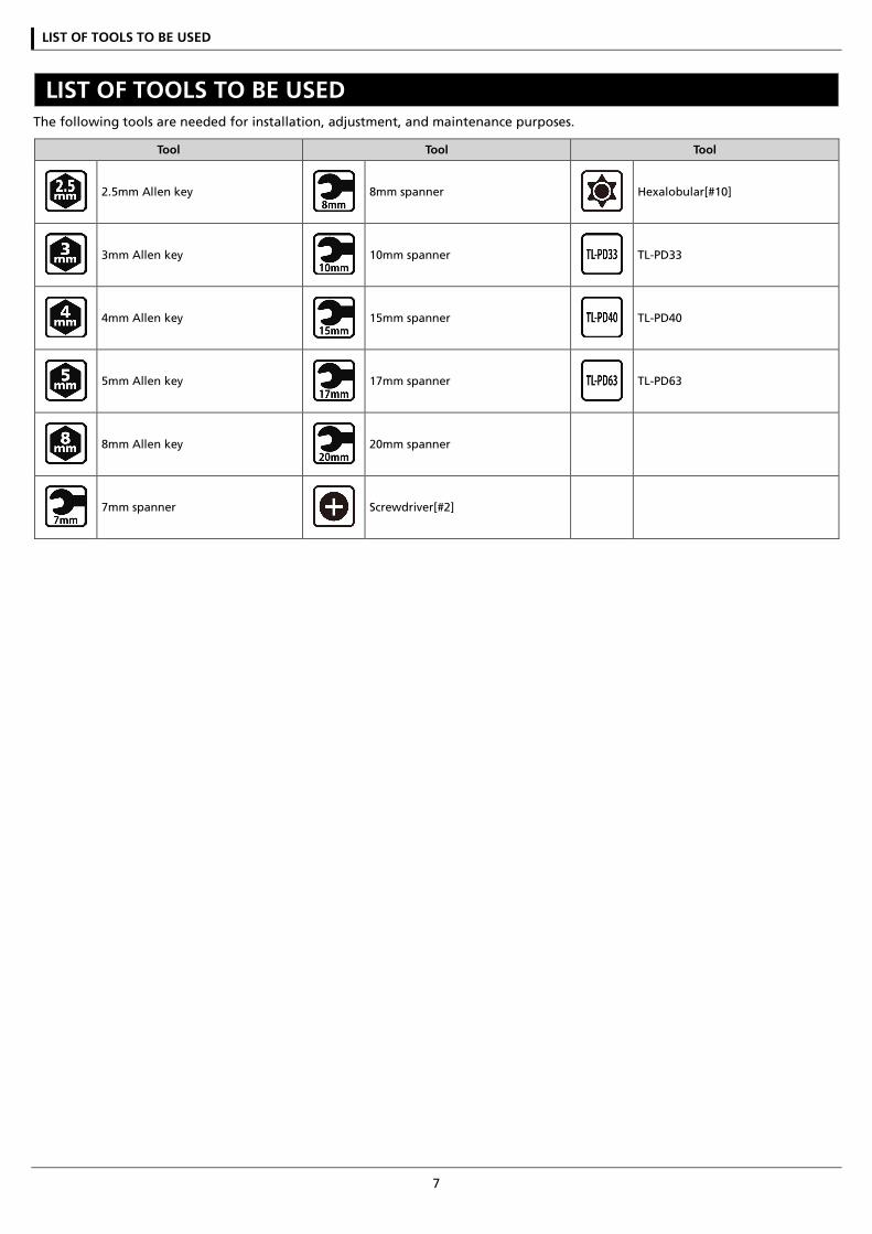
LIST OF TOOLS TO BE USED The following tools are needed for installation, adjustment, and maintenance purposes.
Tool Tool Tool
2.5mm Allen key 8mm spanner Hexalobular[#10]
3mm Allen key 10mm spanner TL-PD33
4mm Allen key 15mm spanner TL-PD40
5mm Allen key 17mm spanner TL-PD63
8mm Allen key 20mm spanner
7mm spanner Screwdriver[#2]

INSTALLATION
INSTALLATION
9
INSTALLATION
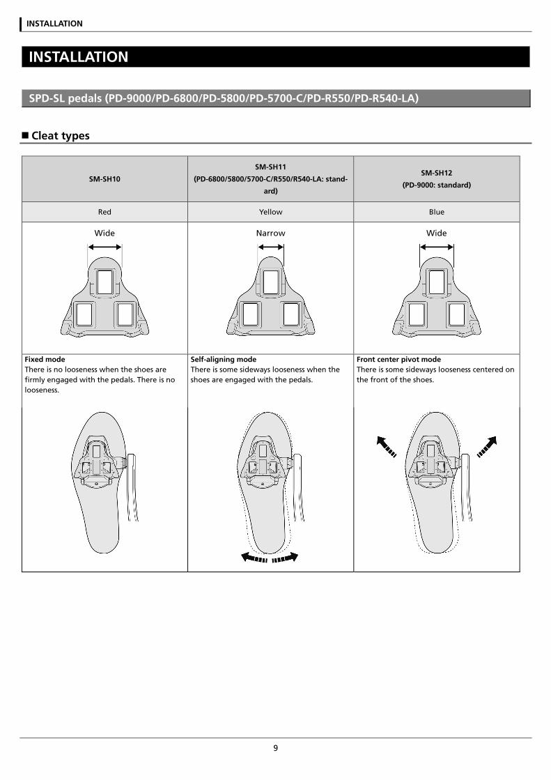
SPD-SL pedals (PD-9000/PD-6800/PD-5800/PD-5700-C/PD-R550/PD-R540-LA)
Cleat types
SM-SH10
SM-SH11
(PD-6800/5800/5700-C/R550/R540-LA: stand-
ard)
SM-SH12
(PD-9000: standard)
Red Yellow Blue
Wide
Narrow
Wide
Fixed mode There is no looseness when the shoes are firmly engaged with the pedals. There is no looseness.
Self-aligning mode There is some sideways looseness when the shoes are engaged with the pedals.
Front center pivot mode There is some sideways looseness centered on the front of the shoes.
INSTALLATION
10
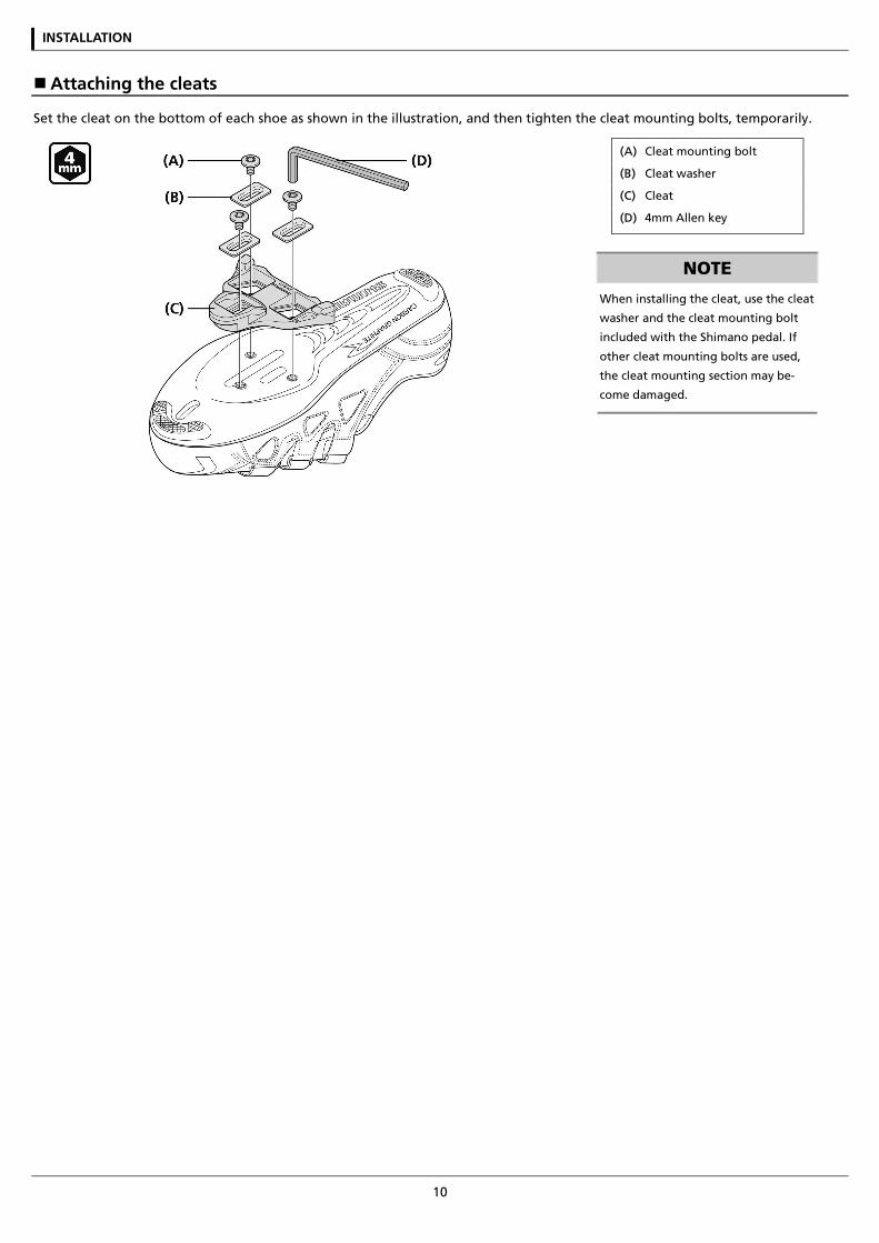
Attaching the cleats
Set the cleat on the bottom of each shoe as shown in the illustration, and then tighten the cleat mounting bolts, temporarily.
(A) Cleat mounting bolt
(B) Cleat washer
(C) Cleat
(D) 4mm Allen key
NOTE
When installing the cleat, use the cleat
washer and the cleat mounting bolt
included with the Shimano pedal. If
other cleat mounting bolts are used,
the cleat mounting section may be-
come damaged.
INSTALLATION
11
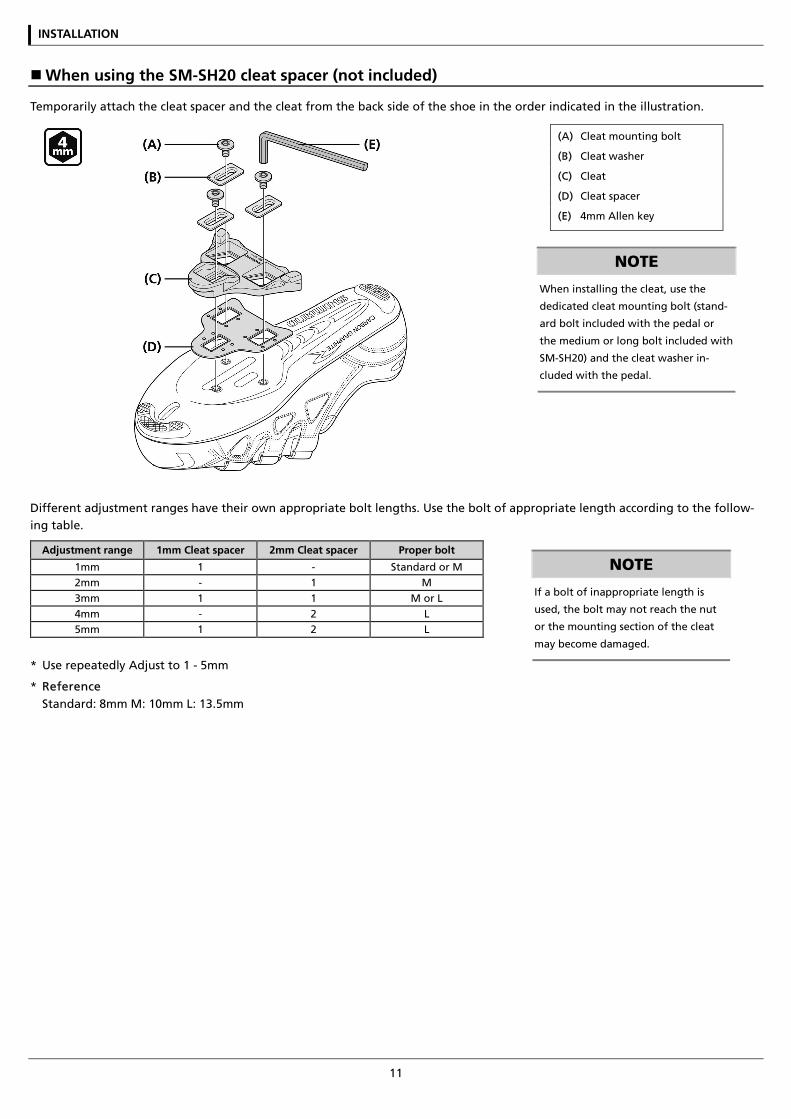
When using the SM-SH20 cleat spacer (not included)
Temporarily attach the cleat spacer and the cleat from the back side of the shoe in the order indicated in the illustration.
(A) Cleat mounting bolt
(B) Cleat washer
(C) Cleat
(D) Cleat spacer
(E) 4mm Allen key
NOTE
When installing the cleat, use the
dedicated cleat mounting bolt (stand-
ard bolt included with the pedal or
the medium or long bolt included with
SM-SH20) and the cleat washer in-
cluded with the pedal.
Different adjustment ranges have their own appropriate bolt lengths. Use the bolt of appropriate length according to the follow-ing table.
Adjustment range 1mm Cleat spacer 2mm Cleat spacer Proper bolt
1mm 1 - Standard or M 2mm - 1 M 3mm 1 1 M or L 4mm - 2 L 5mm 1 2 L
* Use repeatedly Adjust to 1 - 5mm
* Reference Standard: 8mm M: 10mm L: 13.5mm
NOTE
If a bolt of inappropriate length is
used, the bolt may not reach the nut
or the mounting section of the cleat
may become damaged.
INSTALLATION
12
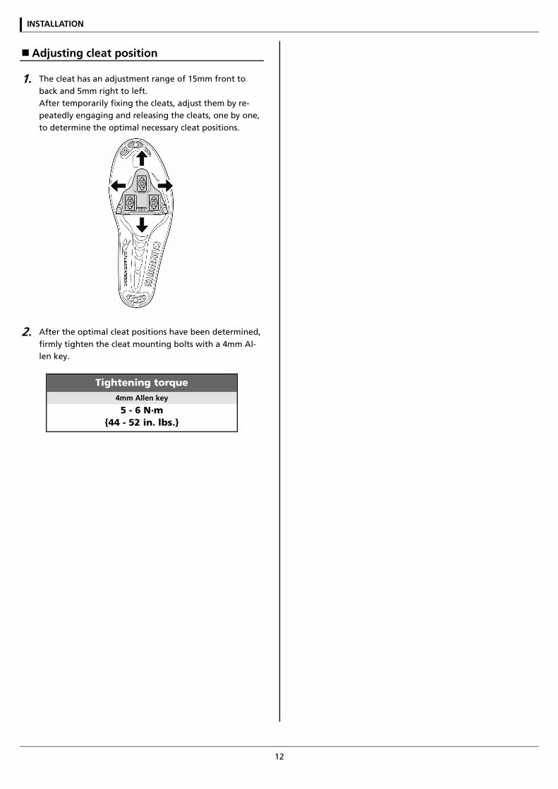
Adjusting cleat position
1. The cleat has an adjustment range of 15mm front to back and 5mm right to left. After temporarily fixing the cleats, adjust them by re-peatedly engaging and releasing the cleats, one by one, to determine the optimal necessary cleat positions.
2. After the optimal cleat positions have been determined, firmly tighten the cleat mounting bolts with a 4mm Al-len key.
Tightening torque 4mm Allen key
5 - 6 N·m {44 - 52 in. lbs.}
INSTALLATION
13
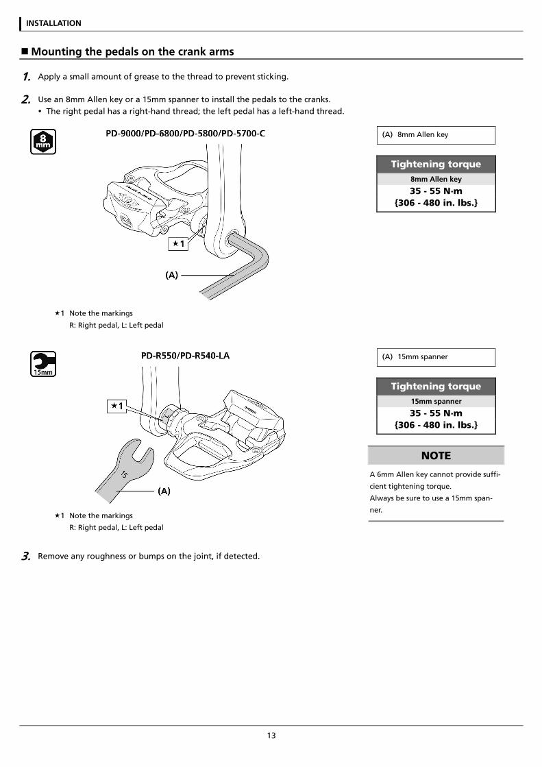
Mounting the pedals on the crank arms
1. Apply a small amount of grease to the thread to prevent sticking.
2. Use an 8mm Allen key or a 15mm spanner to install the pedals to the cranks. The right pedal has a right-hand thread; the left pedal has a left-hand thread.
1 Note the markings
R: Right pedal, L: Left pedal
(A) 8mm Allen key
Tightening torque 8mm Allen key
35 - 55 N·m {306 - 480 in. lbs.}
1 Note the markings
R: Right pedal, L: Left pedal
(A) 15mm spanner
Tightening torque 15mm spanner
35 - 55 N·m {306 - 480 in. lbs.}
NOTE
A 6mm Allen key cannot provide suffi-
cient tightening torque.
Always be sure to use a 15mm span-
ner.
3. Remove any roughness or bumps on the joint, if detected.
INSTALLATION
14
SPD pedals/Click’R (Single release mode cleats: SM-SH51/Multiple release mode cleats: SM-SH56)
Cleat types
Single release mode cleats SM-SH51 (black)
Multiple release mode cleats SM-SH56 (silver, gold)
1 Front
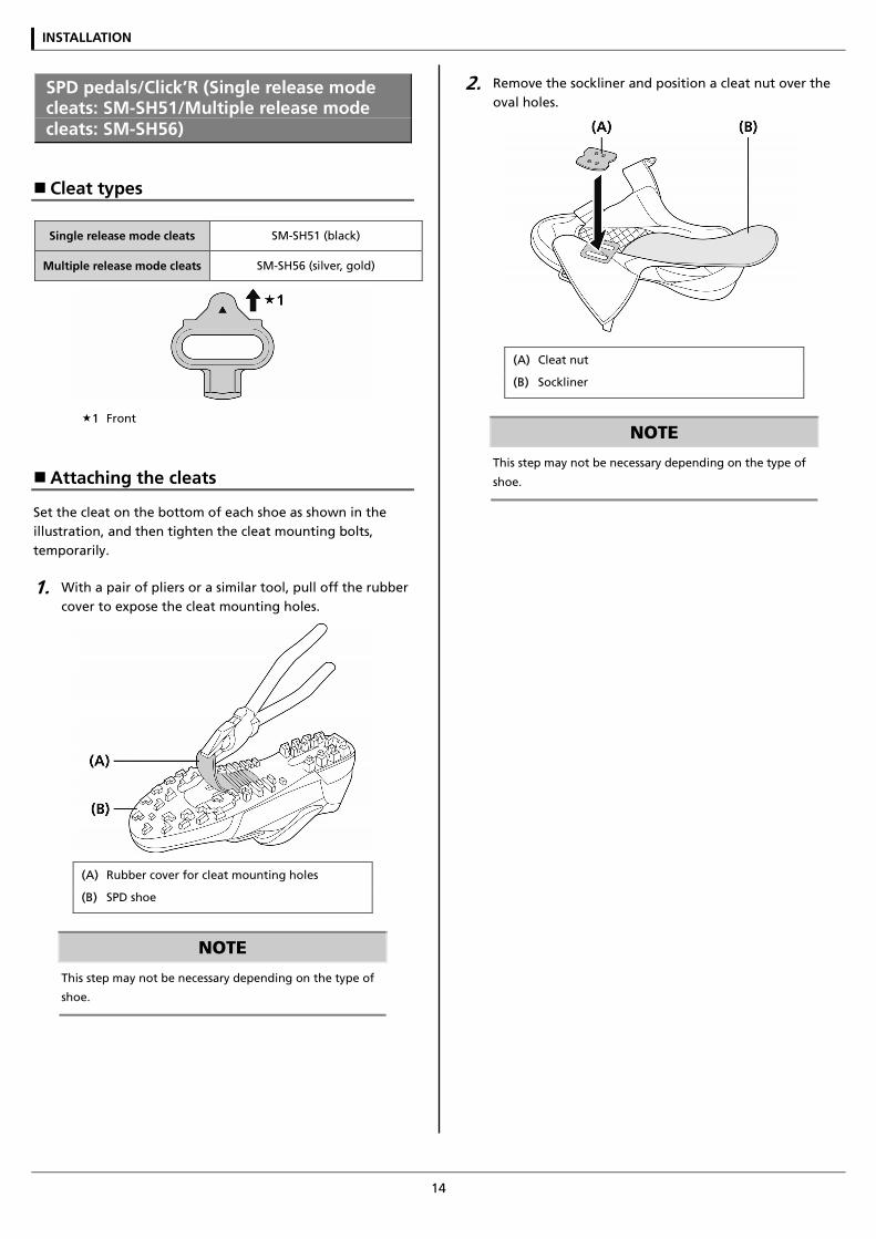
Attaching the cleats
Set the cleat on the bottom of each shoe as shown in the illustration, and then tighten the cleat mounting bolts, temporarily.
1. With a pair of pliers or a similar tool, pull off the rubber cover to expose the cleat mounting holes.
(A) Rubber cover for cleat mounting holes
(B) SPD shoe
NOTE
This step may not be necessary depending on the type of
shoe.
2. Remove the sockliner and position a cleat nut over the oval holes.
(A) Cleat nut
(B) Sockliner
NOTE
This step may not be necessary depending on the type of
shoe.
INSTALLATION
15
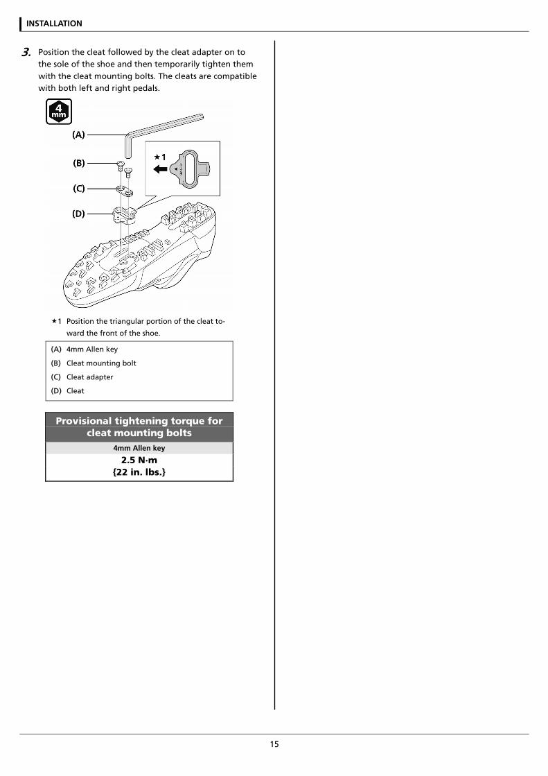
3. Position the cleat followed by the cleat adapter on to the sole of the shoe and then temporarily tighten them with the cleat mounting bolts. The cleats are compatible with both left and right pedals.
1 Position the triangular portion of the cleat to-
ward the front of the shoe.
(A) 4mm Allen key
(B) Cleat mounting bolt
(C) Cleat adapter
(D) Cleat
Provisional tightening torque for cleat mounting bolts
4mm Allen key
2.5 N·m {22 in. lbs.}
INSTALLATION
16
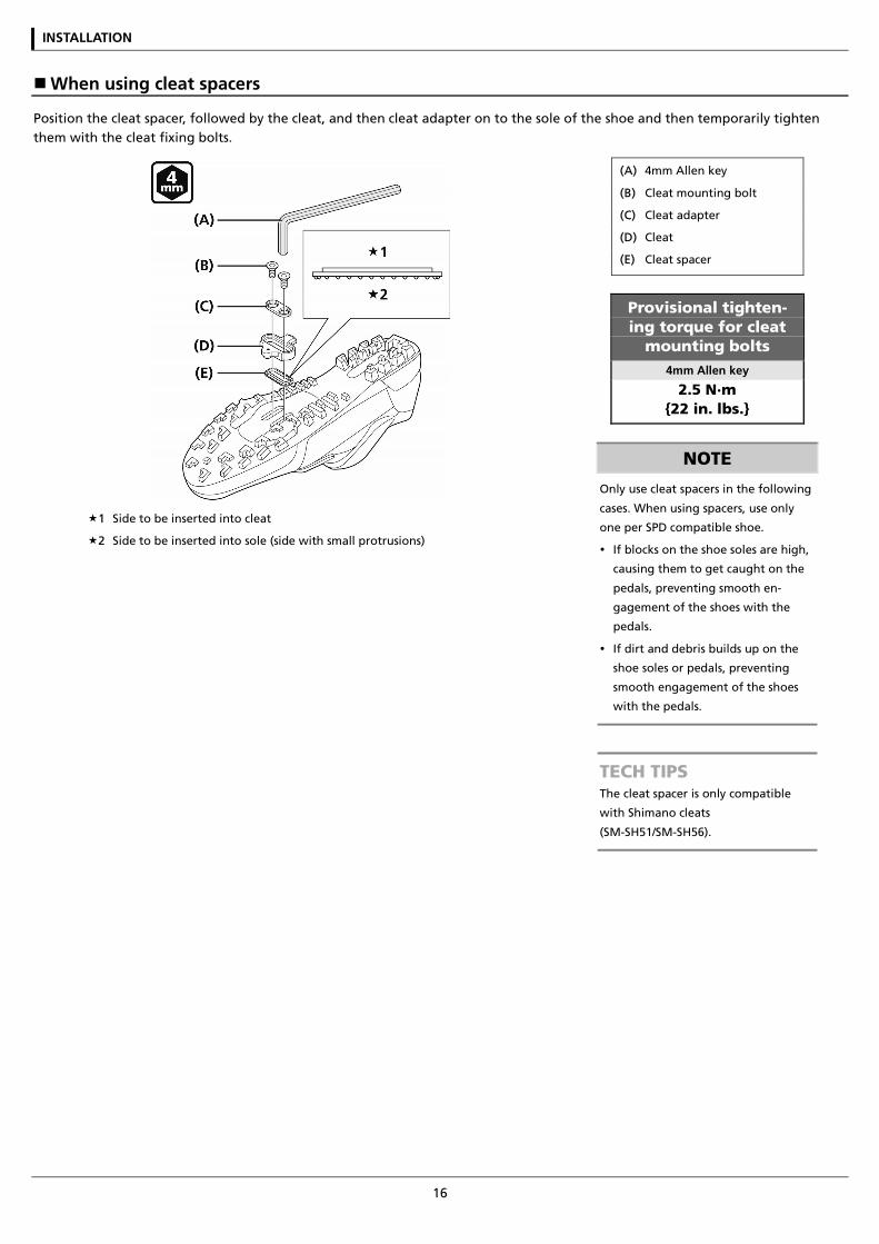
When using cleat spacers
Position the cleat spacer, followed by the cleat, and then cleat adapter on to the sole of the shoe and then temporarily tighten them with the cleat fixing bolts.
1 Side to be inserted into cleat
2 Side to be inserted into sole (side with small protrusions)
(A) 4mm Allen key
(B) Cleat mounting bolt
(C) Cleat adapter
(D) Cleat
(E) Cleat spacer
Provisional tighten-ing torque for cleat
mounting bolts 4mm Allen key
2.5 N·m {22 in. lbs.}
NOTE
Only use cleat spacers in the following
cases. When using spacers, use only
one per SPD compatible shoe.
If blocks on the shoe soles are high,
causing them to get caught on the
pedals, preventing smooth en-
gagement of the shoes with the
pedals.
If dirt and debris builds up on the
shoe soles or pedals, preventing
smooth engagement of the shoes
with the pedals.
TECH TIPS The cleat spacer is only compatible
with Shimano cleats
(SM-SH51/SM-SH56).
INSTALLATION
17
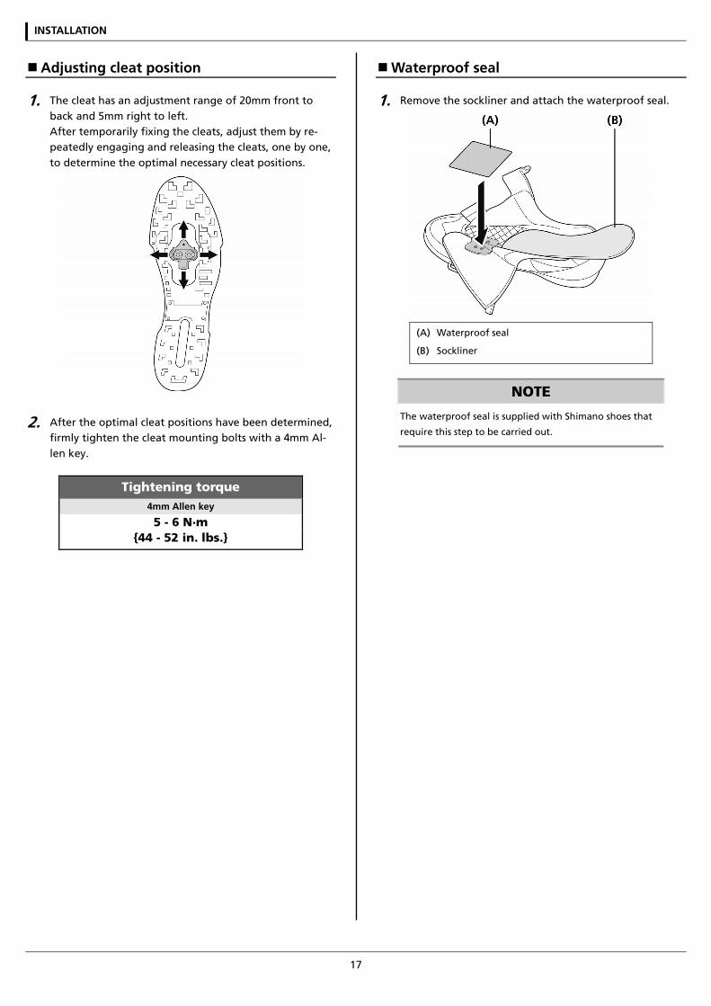
Adjusting cleat position
1. The cleat has an adjustment range of 20mm front to back and 5mm right to left. After temporarily fixing the cleats, adjust them by re-peatedly engaging and releasing the cleats, one by one, to determine the optimal necessary cleat positions.
2. After the optimal cleat positions have been determined, firmly tighten the cleat mounting bolts with a 4mm Al-len key.
Tightening torque 4mm Allen key
5 - 6 N·m {44 - 52 in. lbs.}
Waterproof seal
1. Remove the sockliner and attach the waterproof seal.
(A) Waterproof seal
(B) Sockliner
NOTE
The waterproof seal is supplied with Shimano shoes that
require this step to be carried out.
INSTALLATION
18
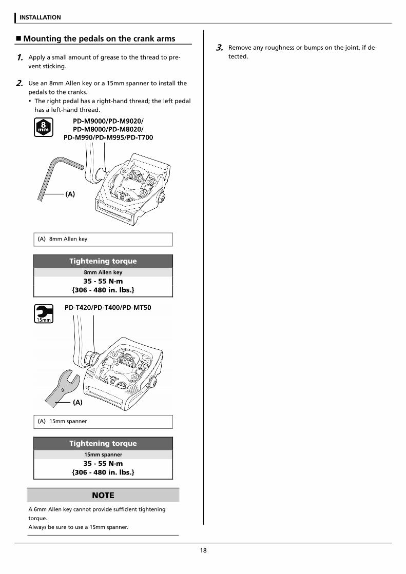
Mounting the pedals on the crank arms
1. Apply a small amount of grease to the thread to pre-vent sticking.
2. Use an 8mm Allen key or a 15mm spanner to install the pedals to the cranks. The right pedal has a right-hand thread; the left pedal
has a left-hand thread.
(A) 8mm Allen key
Tightening torque 8mm Allen key
35 - 55 N·m {306 - 480 in. lbs.}
(A) 15mm spanner
Tightening torque 15mm spanner
35 - 55 N·m {306 - 480 in. lbs.}
NOTE
A 6mm Allen key cannot provide sufficient tightening
torque.
Always be sure to use a 15mm spanner.
3. Remove any roughness or bumps on the joint, if de-tected.

MAINTENANCE
MAINTENANCE
20
MAINTENANCE
SPD-SL pedals (PD-9000/PD-6800/PD-5800/PD-5700-C/ PD-R550/PD-R540-LA)
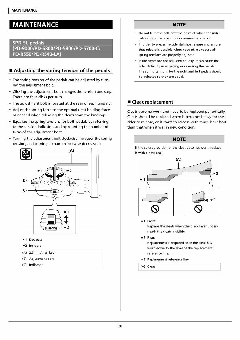
Adjusting the spring tension of the pedals
The spring tension of the pedals can be adjusted by turn-ing the adjustment bolt.
Clicking the adjustment bolt changes the tension one step. There are four clicks per turn.
The adjustment bolt is located at the rear of each binding.
Adjust the spring force to the optimal cleat holding force as needed when releasing the cleats from the bindings.
Equalize the spring tensions for both pedals by referring to the tension indicators and by counting the number of turns of the adjustment bolts.
Turning the adjustment bolt clockwise increases the spring tension, and turning it counterclockwise decreases it.
1 Decrease
2 Increase
(A) 2.5mm Allen key
(B) Adjustment bolt
(C) Indicator
NOTE
Do not turn the bolt past the point at which the indi-
cator shows the maximum or minimum tension.
In order to prevent accidental shoe release and ensure
that release is possible when needed, make sure all
spring tensions are properly adjusted.
If the cleats are not adjusted equally, it can cause the
rider difficulty in engaging or releasing the pedals.
The spring tensions for the right and left pedals should
be adjusted so they are equal.
Cleat replacement
Cleats become worn and need to be replaced periodically. Cleats should be replaced when it becomes heavy for the rider to release, or it starts to release with much less effort than that when it was in new condition.
NOTE
If the colored portion of the cleat becomes worn, replace
it with a new one.
1 Front:
Replace the cleats when the black layer under-
neath the cleats is visible.
2 Rear:
Replacement is required once the cleat has
worn down to the level of the replacement
reference line.
3 Replacement reference line
(A) Cleat
MAINTENANCE
21
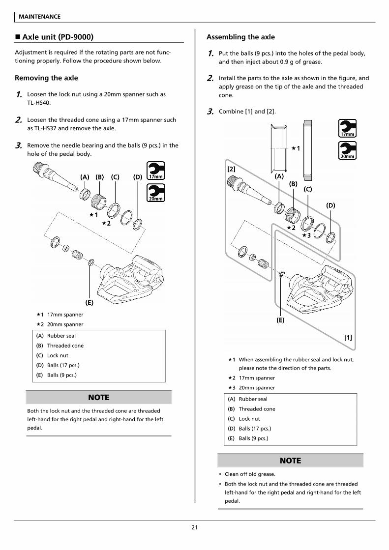
Axle unit (PD-9000)
Adjustment is required if the rotating parts are not func-tioning properly. Follow the procedure shown below.
Removing the axle
1. Loosen the lock nut using a 20mm spanner such as TL-HS40.
2. Loosen the threaded cone using a 17mm spanner such as TL-HS37 and remove the axle.
3. Remove the needle bearing and the balls (9 pcs.) in the hole of the pedal body.
1 17mm spanner
2 20mm spanner
(A) Rubber seal
(B) Threaded cone
(C) Lock nut
(D) Balls (17 pcs.)
(E) Balls (9 pcs.)
NOTE
Both the lock nut and the threaded cone are threaded
left-hand for the right pedal and right-hand for the left
pedal.
Assembling the axle
1. Put the balls (9 pcs.) into the holes of the pedal body, and then inject about 0.9 g of grease.
2. Install the parts to the axle as shown in the figure, and apply grease on the tip of the axle and the threaded cone.
3. Combine [1] and [2].
1 When assembling the rubber seal and lock nut,
please note the direction of the parts.
2 17mm spanner
3 20mm spanner
(A) Rubber seal
(B) Threaded cone
(C) Lock nut
(D) Balls (17 pcs.)
(E) Balls (9 pcs.)
NOTE
Clean off old grease.
Both the lock nut and the threaded cone are threaded
left-hand for the right pedal and right-hand for the left
pedal.
MAINTENANCE
22
Adjustment of axle rotation
1. Turn the threaded cone by using a 17mm spanner to adjust rotation.
2. With the threaded cone fixed, tighten the lock nut (20mm).
Tightening torque 20mm spanner
10 - 15 N·m {88 - 131 in. lbs.}
NOTE
Adjust so as to achieve a smooth rotation without loose-
ness when the axle unit is set into the pedal.
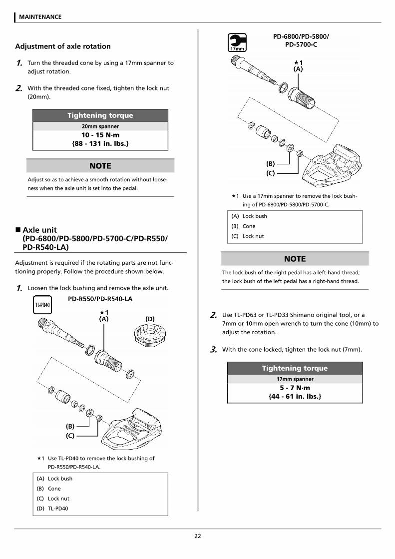
Axle unit (PD-6800/PD-5800/PD-5700-C/PD-R550/ PD-R540-LA)
Adjustment is required if the rotating parts are not func-tioning properly. Follow the procedure shown below.
1. Loosen the lock bushing and remove the axle unit.
1 Use TL-PD40 to remove the lock bushing of
PD-R550/PD-R540-LA.
(A) Lock bush
(B) Cone
(C) Lock nut
(D) TL-PD40
1 Use a 17mm spanner to remove the lock bush-
ing of PD-6800/PD-5800/PD-5700-C.
(A) Lock bush
(B) Cone
(C) Lock nut
NOTE
The lock bush of the right pedal has a left-hand thread;
the lock bush of the left pedal has a right-hand thread.
2. Use TL-PD63 or TL-PD33 Shimano original tool, or a 7mm or 10mm open wrench to turn the cone (10mm) to adjust the rotation.
3. With the cone locked, tighten the lock nut (7mm).
Tightening torque 17mm spanner
5 - 7 N·m {44 - 61 in. lbs.}
MAINTENANCE
23
NOTE
Right-hand thread: Black-colored (without slit)
If the fitted lock nut is black-colored (without slit), the
cone and the lock nut have a right-hand thread.
Left-hand thread: Black-colored (with slit), Sil-
ver-colored
If the fitted lock nut is silver-colored or black-colored
(with slit), the cone and the lock nut have a left-hand
thread.
Adjust the cone so as to achieve a smooth rotation
without looseness when the axle unit is set into the
pedal.
TECH TIPS The rotating parts are fastened when the axle unit is set
into the pedal. Adjust them slightly loosely before setup.
4. Remove old grease and apply an appropriate amount of new grease to the bottom of the pedal linkage.
TECH TIPS Apply grease to the extent that it does not flow out when
the axle is set into the pedal (about 1.5g).
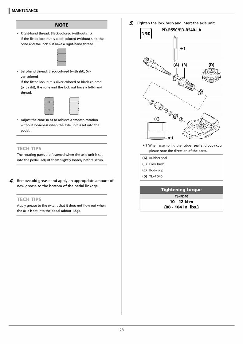
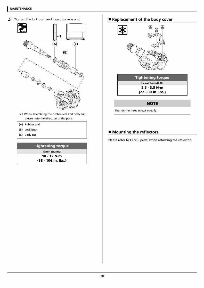
5. Tighten the lock bush and insert the axle unit.
1 When assembling the rubber seal and body cup,
please note the direction of the parts.
(A) Rubber seal
(B) Lock bush
(C) Body cup
(D) TL−PD40
Tightening torque TL−PD40
10 - 12 N·m {88 - 104 in. lbs.}
MAINTENANCE
24
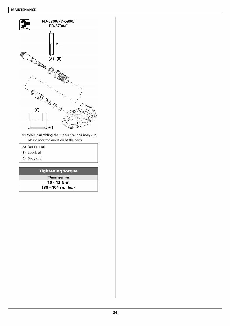
1 When assembling the rubber seal and body cup,
please note the direction of the parts.
(A) Rubber seal
(B) Lock bush
(C) Body cup
Tightening torque 17mm spanner
10 - 12 N·m {88 - 104 in. lbs.}
MAINTENANCE
25
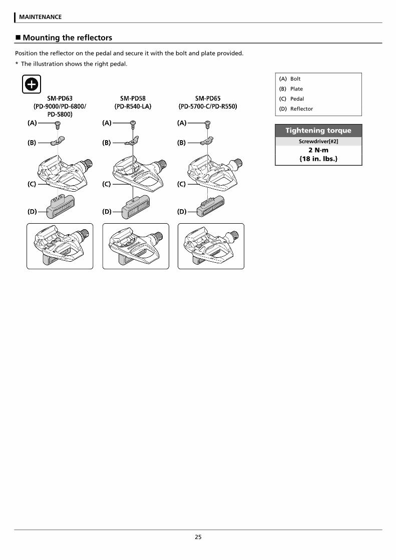
Mounting the reflectors
Position the reflector on the pedal and secure it with the bolt and plate provided.
* The illustration shows the right pedal.
(A) Bolt
(B) Plate
(C) Pedal
(D) Reflector
Tightening torque Screwdriver[#2]
2 N·m {18 in. lbs.}
MAINTENANCE
26
SPD pedals (Single release mode cleats: SM-SH51/Multiple release mode cleats: SM-SH56)
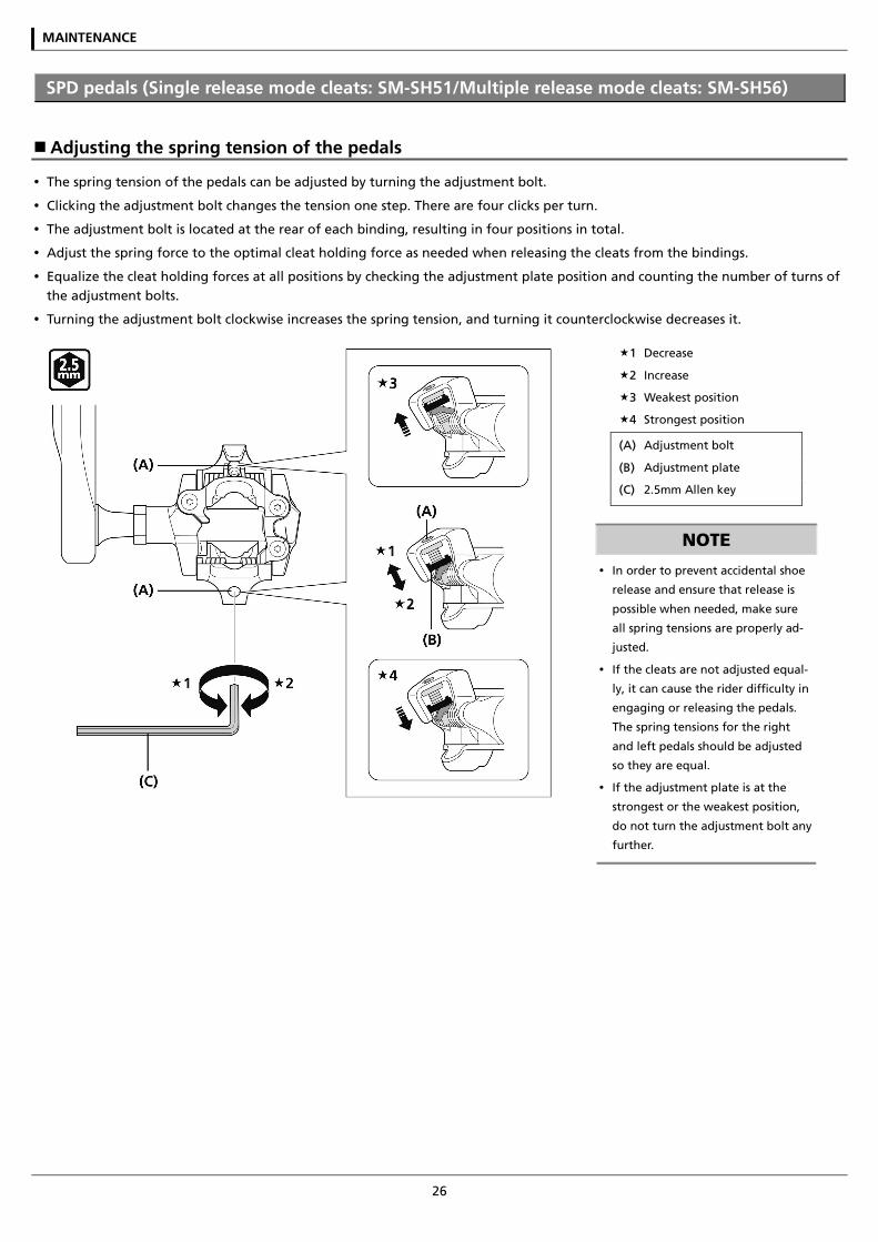
Adjusting the spring tension of the pedals
The spring tension of the pedals can be adjusted by turning the adjustment bolt.
Clicking the adjustment bolt changes the tension one step. There are four clicks per turn.
The adjustment bolt is located at the rear of each binding, resulting in four positions in total.
Adjust the spring force to the optimal cleat holding force as needed when releasing the cleats from the bindings.
Equalize the cleat holding forces at all positions by checking the adjustment plate position and counting the number of turns of the adjustment bolts.
Turning the adjustment bolt clockwise increases the spring tension, and turning it counterclockwise decreases it.
1 Decrease
2 Increase
3 Weakest position
4 Strongest position
(A) Adjustment bolt
(B) Adjustment plate
(C) 2.5mm Allen key
NOTE
In order to prevent accidental shoe
release and ensure that release is
possible when needed, make sure
all spring tensions are properly ad-
justed.
If the cleats are not adjusted equal-
ly, it can cause the rider difficulty in
engaging or releasing the pedals.
The spring tensions for the right
and left pedals should be adjusted
so they are equal.
If the adjustment plate is at the
strongest or the weakest position,
do not turn the adjustment bolt any
further.
MAINTENANCE
27
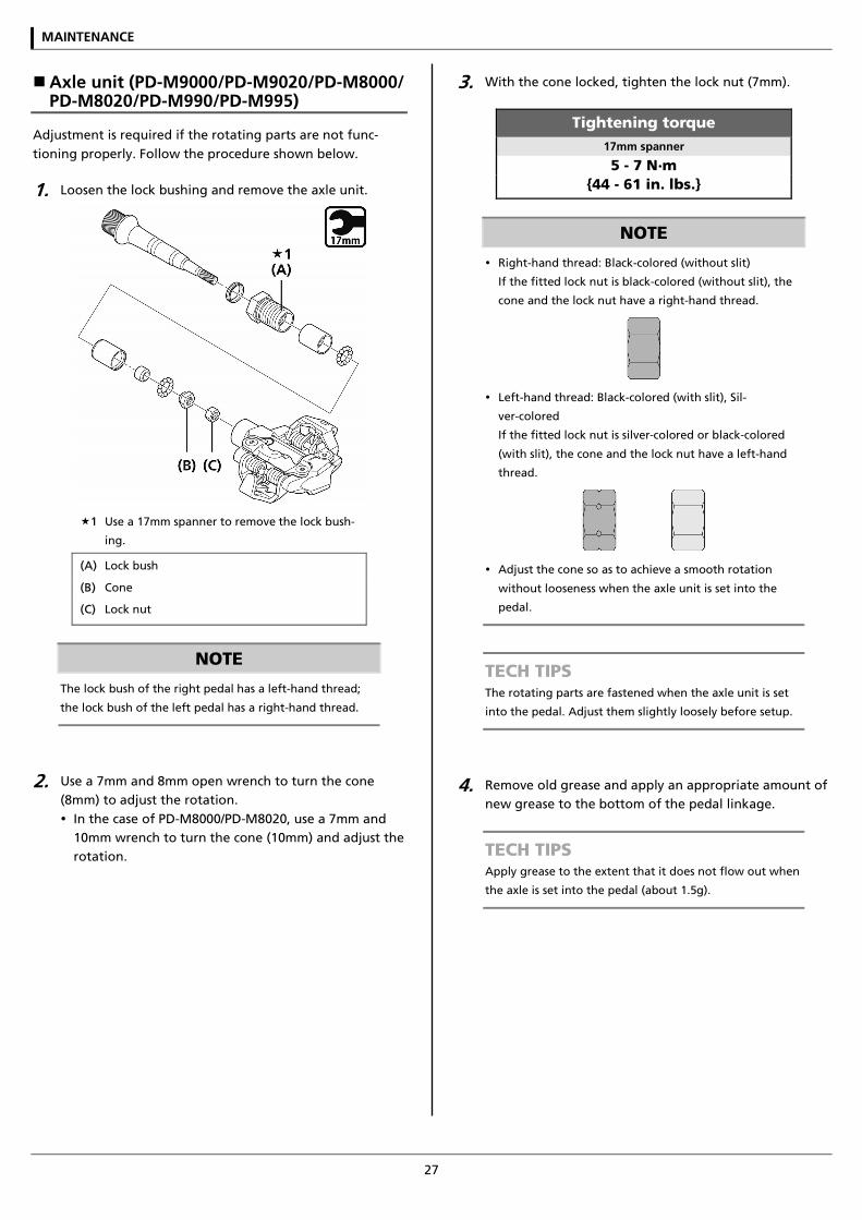
Axle unit (PD-M9000/PD-M9020/PD-M8000/ PD-M8020/PD-M990/PD-M995)
Adjustment is required if the rotating parts are not func-tioning properly. Follow the procedure shown below.
1. Loosen the lock bushing and remove the axle unit.
1 Use a 17mm spanner to remove the lock bush-
ing.
(A) Lock bush
(B) Cone
(C) Lock nut
NOTE
The lock bush of the right pedal has a left-hand thread;
the lock bush of the left pedal has a right-hand thread.
2. Use a 7mm and 8mm open wrench to turn the cone (8mm) to adjust the rotation. In the case of PD-M8000/PD-M8020, use a 7mm and
10mm wrench to turn the cone (10mm) and adjust the rotation.
3. With the cone locked, tighten the lock nut (7mm).
Tightening torque 17mm spanner
5 - 7 N·m {44 - 61 in. lbs.}
NOTE
Right-hand thread: Black-colored (without slit)
If the fitted lock nut is black-colored (without slit), the
cone and the lock nut have a right-hand thread.
Left-hand thread: Black-colored (with slit), Sil-
ver-colored
If the fitted lock nut is silver-colored or black-colored
(with slit), the cone and the lock nut have a left-hand
thread.
Adjust the cone so as to achieve a smooth rotation
without looseness when the axle unit is set into the
pedal.
TECH TIPS The rotating parts are fastened when the axle unit is set
into the pedal. Adjust them slightly loosely before setup.
4. Remove old grease and apply an appropriate amount of new grease to the bottom of the pedal linkage.
TECH TIPS Apply grease to the extent that it does not flow out when
the axle is set into the pedal (about 1.5g).
MAINTENANCE
28
5. Tighten the lock bush and insert the axle unit.
1 When assembling the rubber seal and body cup,
please note the direction of the parts.
(A) Rubber seal
(B) Lock bush
(C) Body cup
Tightening torque 17mm spanner
10 - 12 N·m {88 - 104 in. lbs.}
Replacement of the body cover
Tightening torque Hexalobular[#10]
2.5 - 3.5 N·m {22 - 30 in. lbs.}
NOTE
Tighten the three screws equally.
Mounting the reflectors
Please refer to Click'R pedal when attaching the reflector.
MAINTENANCE
29
Click'R (Single release mode cleats: SM-SH51/Multiple release mode cleats: SM-SH56)
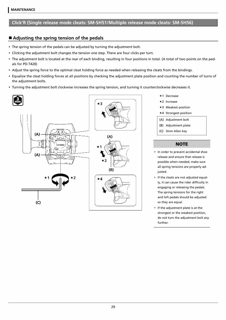
Adjusting the spring tension of the pedals
The spring tension of the pedals can be adjusted by turning the adjustment bolt.
Clicking the adjustment bolt changes the tension one step. There are four clicks per turn.
The adjustment bolt is located at the rear of each binding, resulting in four positions in total. (A total of two points on the ped-als for PD-T420)
Adjust the spring force to the optimal cleat holding force as needed when releasing the cleats from the bindings.
Equalize the cleat holding forces at all positions by checking the adjustment plate position and counting the number of turns of the adjustment bolts.
Turning the adjustment bolt clockwise increases the spring tension, and turning it counterclockwise decreases it.
1 Decrease
2 Increase
3 Weakest position
4 Strongest position
(A) Adjustment bolt
(B) Adjustment plate
(C) 3mm Allen key
NOTE
In order to prevent accidental shoe
release and ensure that release is
possible when needed, make sure
all spring tensions are properly ad-
justed.
If the cleats are not adjusted equal-
ly, it can cause the rider difficulty in
engaging or releasing the pedals.
The spring tensions for the right
and left pedals should be adjusted
so they are equal.
If the adjustment plate is at the
strongest or the weakest position,
do not turn the adjustment bolt any
further.
MAINTENANCE
30
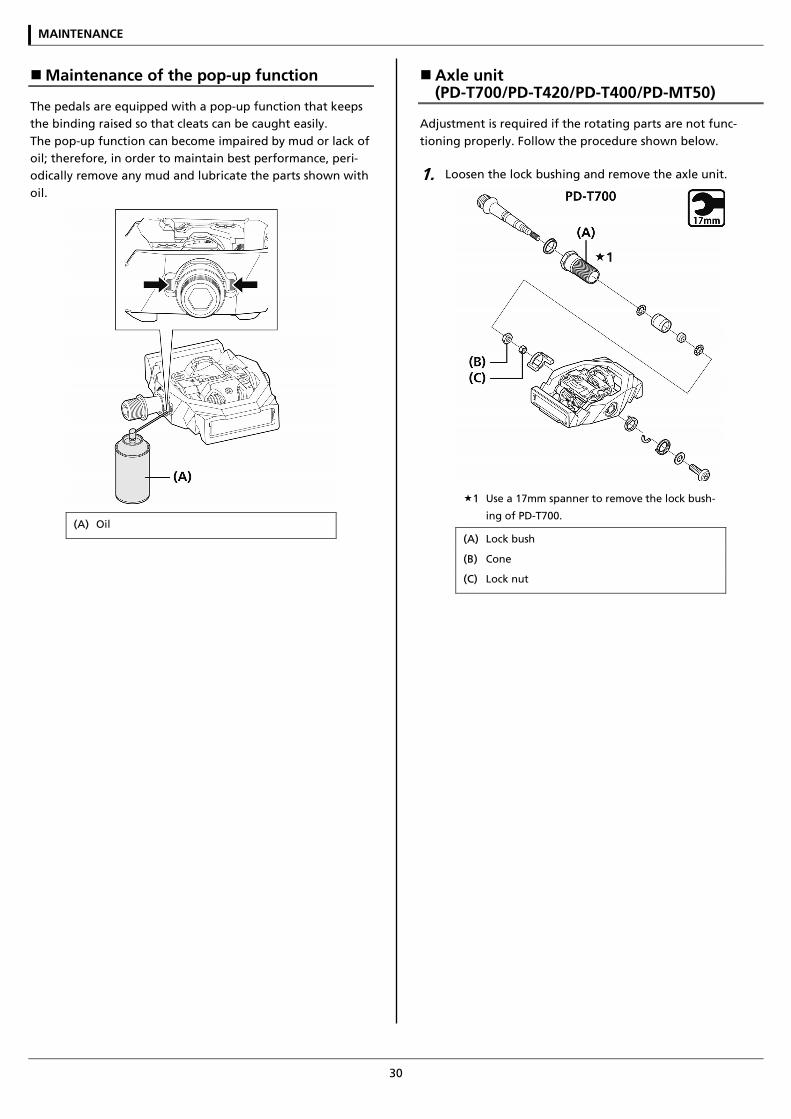
Maintenance of the pop-up function
The pedals are equipped with a pop-up function that keeps the binding raised so that cleats can be caught easily. The pop-up function can become impaired by mud or lack of oil; therefore, in order to maintain best performance, peri-odically remove any mud and lubricate the parts shown with oil.
(A) Oil
Axle unit (PD-T700/PD-T420/PD-T400/PD-MT50)
Adjustment is required if the rotating parts are not func-tioning properly. Follow the procedure shown below.
1. Loosen the lock bushing and remove the axle unit.
1 Use a 17mm spanner to remove the lock bush-
ing of PD-T700.
(A) Lock bush
(B) Cone
(C) Lock nut
MAINTENANCE
31
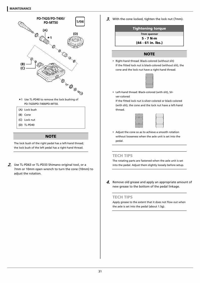
1 Use TL-PD40 to remove the lock bushing of
PD-T420/PD-T400/PD-MT50.
(A) Lock bush
(B) Cone
(C) Lock nut
(D) TL-PD40
NOTE
The lock bush of the right pedal has a left-hand thread;
the lock bush of the left pedal has a right-hand thread.
2. Use TL-PD63 or TL-PD33 Shimano original tool, or a 7mm or 10mm open wrench to turn the cone (10mm) to adjust the rotation.
3. With the cone locked, tighten the lock nut (7mm).
Tightening torque 7mm spanner
5 - 7 N·m {44 - 61 in. lbs.}
NOTE
Right-hand thread: Black-colored (without slit)
If the fitted lock nut is black-colored (without slit), the
cone and the lock nut have a right-hand thread.
Left-hand thread: Black-colored (with slit), Sil-
ver-colored
If the fitted lock nut is silver-colored or black-colored
(with slit), the cone and the lock nut have a left-hand
thread.
Adjust the cone so as to achieve a smooth rotation
without looseness when the axle unit is set into the
pedal.
TECH TIPS The rotating parts are fastened when the axle unit is set
into the pedal. Adjust them slightly loosely before setup.
4. Remove old grease and apply an appropriate amount of new grease to the bottom of the pedal linkage.
TECH TIPS Apply grease to the extent that it does not flow out when
the axle is set into the pedal (about 1.5g).
MAINTENANCE
32
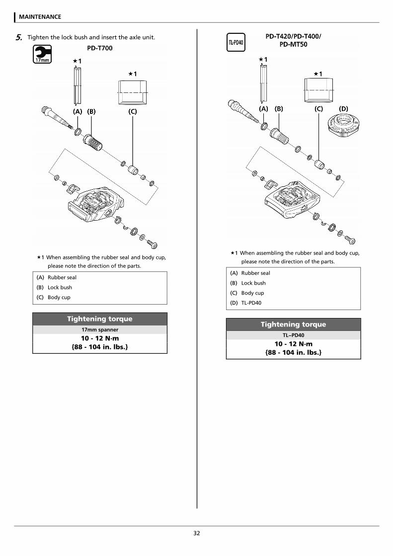
5. Tighten the lock bush and insert the axle unit.
1 When assembling the rubber seal and body cup,
please note the direction of the parts.
(A) Rubber seal
(B) Lock bush
(C) Body cup
Tightening torque 17mm spanner
10 - 12 N·m {88 - 104 in. lbs.}
1 When assembling the rubber seal and body cup,
please note the direction of the parts.
(A) Rubber seal
(B) Lock bush
(C) Body cup
(D) TL-PD40
Tightening torque TL−PD40
10 - 12 N·m {88 - 104 in. lbs.}
MAINTENANCE
33
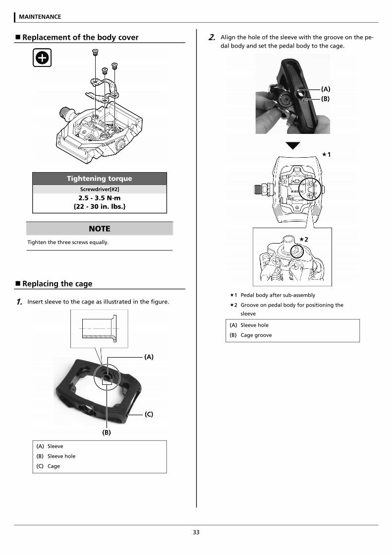
Replacement of the body cover
Tightening torque Screwdriver[#2]
2.5 - 3.5 N·m {22 - 30 in. lbs.}
NOTE
Tighten the three screws equally.
Replacing the cage
1. Insert sleeve to the cage as illustrated in the figure.
(A) Sleeve
(B) Sleeve hole
(C) Cage
2. Align the hole of the sleeve with the groove on the pe-dal body and set the pedal body to the cage.
1 Pedal body after sub-assembly
2 Groove on pedal body for positioning the
sleeve
(A) Sleeve hole
(B) Cage groove
MAINTENANCE
34
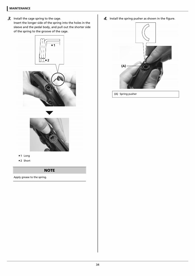
3. Install the cage spring to the cage. Insert the longer side of the spring into the holes in the sleeve and the pedal body, and pull out the shorter side of the spring to the groove of the cage.
1 Long
2 Short
NOTE
Apply grease to the spring.
4. Install the spring pusher as shown in the figure.
(A) Spring pusher
MAINTENANCE
35
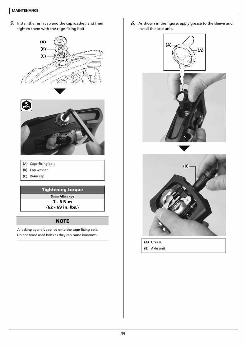
5. Install the resin cap and the cap washer, and then tighten them with the cage-fixing bolt.
(A) Cage-fixing bolt
(B) Cap washer
(C) Resin cap
Tightening torque 5mm Allen key
7 - 8 N·m {62 - 69 in. lbs.}
NOTE
A locking agent is applied onto the cage-fixing bolt.
Do not reuse used bolts as they can cause looseness.
6. As shown in the figure, apply grease to the sleeve and install the axle unit.
(A) Grease
(B) Axle unit
MAINTENANCE
36
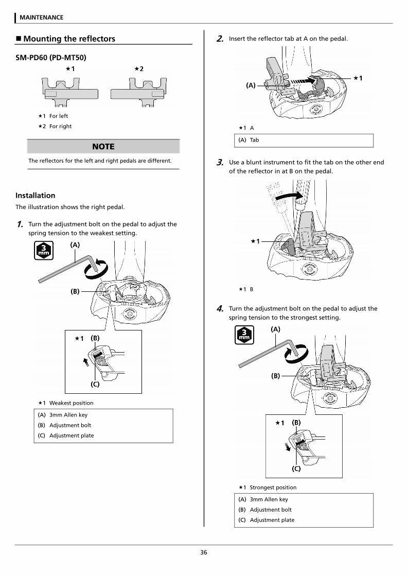
Mounting the reflectors
SM-PD60 (PD-MT50)
1 For left
2 For right
NOTE
The reflectors for the left and right pedals are different.
Installation The illustration shows the right pedal.
1. Turn the adjustment bolt on the pedal to adjust the spring tension to the weakest setting.
1 Weakest position
(A) 3mm Allen key
(B) Adjustment bolt
(C) Adjustment plate
2. Insert the reflector tab at A on the pedal.
1 A
(A) Tab
3. Use a blunt instrument to fit the tab on the other end of the reflector in at B on the pedal.
1 B
4. Turn the adjustment bolt on the pedal to adjust the spring tension to the strongest setting.
1 Strongest position
(A) 3mm Allen key
(B) Adjustment bolt
(C) Adjustment plate
MAINTENANCE
37
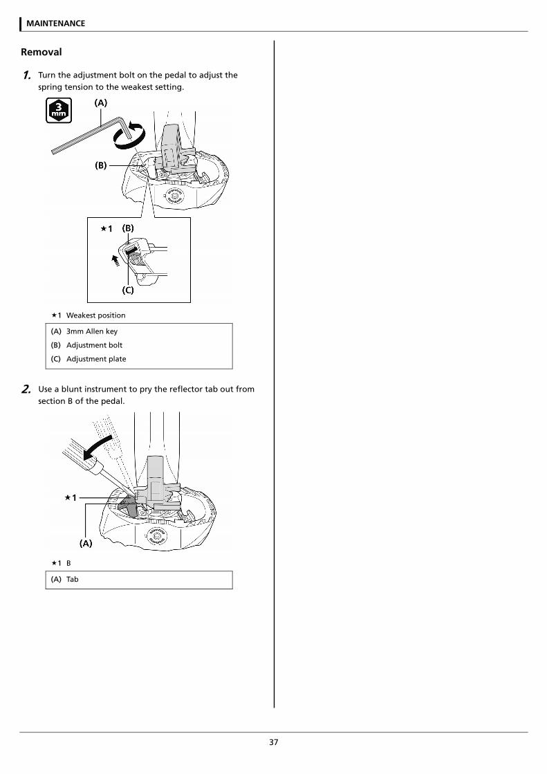
Removal
1. Turn the adjustment bolt on the pedal to adjust the spring tension to the weakest setting.
1 Weakest position
(A) 3mm Allen key
(B) Adjustment bolt
(C) Adjustment plate
2. Use a blunt instrument to pry the reflector tab out from section B of the pedal.
1 B
(A) Tab

Please note: specifications are subject to change for improvement without notice. (English) © March 2016 by Shimano Inc. HTR