p.e. civil exam review: structural analysisstructural · pdf filep.e. civil exam review:...
TRANSCRIPT

Structures
• Determinate• Determinate
• Indeterminate

STATICALLY DETERMINATESTATICALLY DETERMINATE
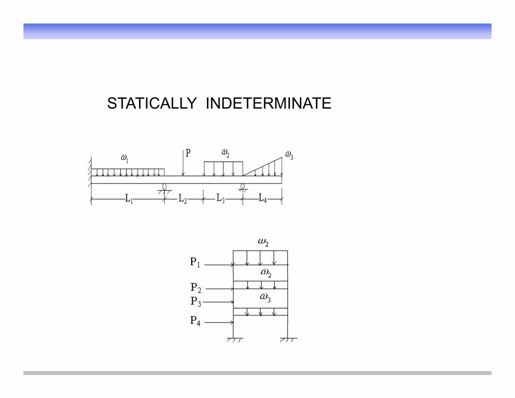
STATICALLY INDETERMINATE

Stability and Determinacy of Trusses
400 lb.300 lb.
C DB C D
7.5 ft
A
10 ft 10 ft 10 ft 10 ftE
FGH
R
A
RLRR
2j = m + r Truss is determinate
2j m + r indeterminate
J = number of jointsm= number of membersr = number of reactions
2j m + r Unstable
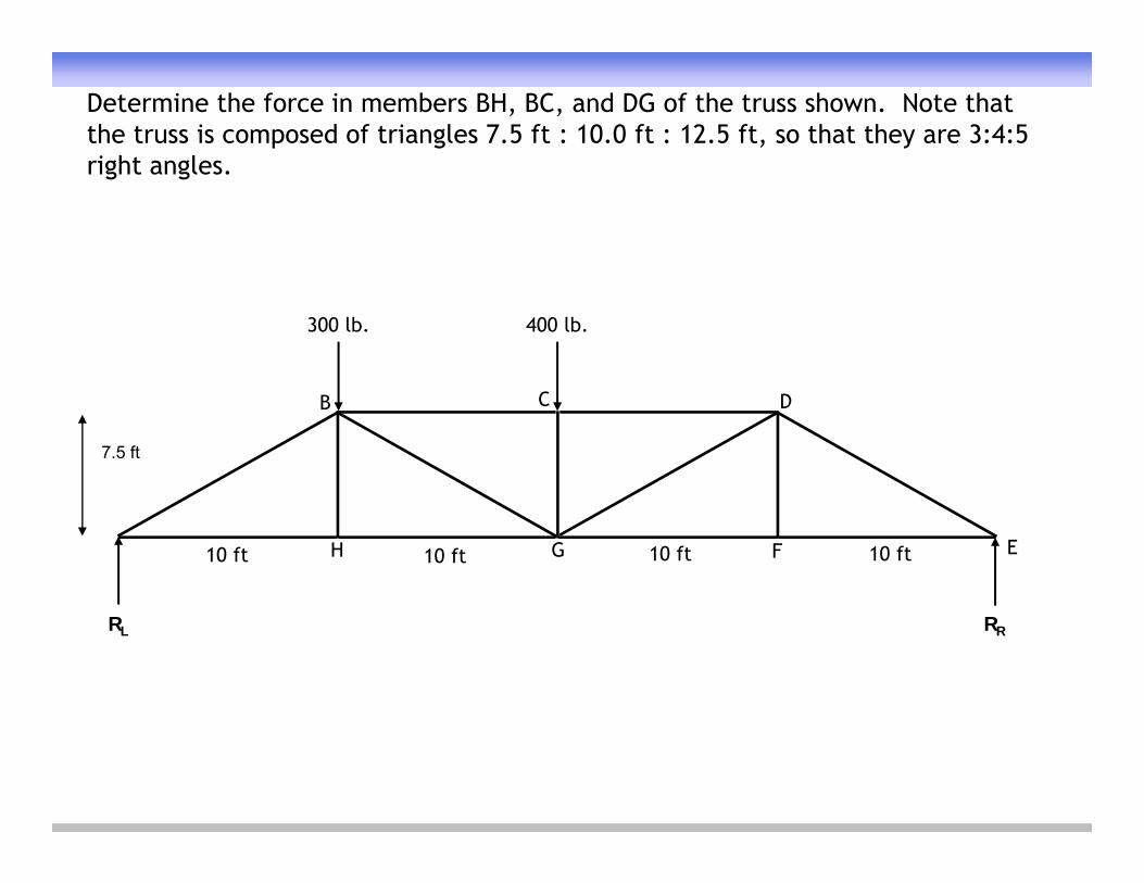
Determine the force in members BH, BC, and DG of the truss shown. Note that the truss is composed of triangles 7.5 ft : 10.0 ft : 12.5 ft, so that they are 3:4:5 right anglesright angles.
400 lb.300 lb.
B C D
7.5 ft
10 ft 10 ft 10 ft 10 ft EFGH
RL RR
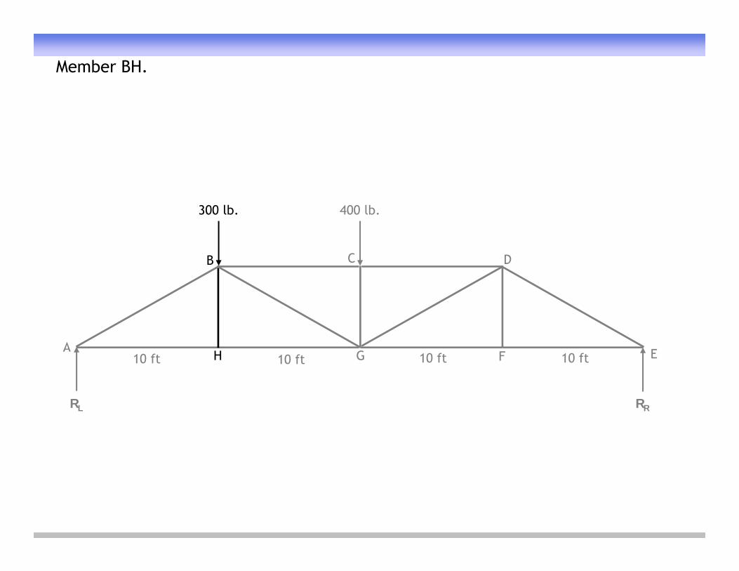
Member BH.
400 lb.300 lb.
B C D
10 ft 10 ft 10 ft 10 ftA EFGH
RL RR

Analysis of Member BH.
400 lb300 lb 400 lb.300 lb.
B C D
10 ft 10 ft 10 ft 10 ftA EFGH
RL RR
FBH
00 bhy FF+
Applying Equation of Equilibrium to Joint H
FHGFAH
HH

Member BC.
400 lb.300 lb.
B C D
10 ft 10 ft 10 ft 10 ftA EFGH
RL RR
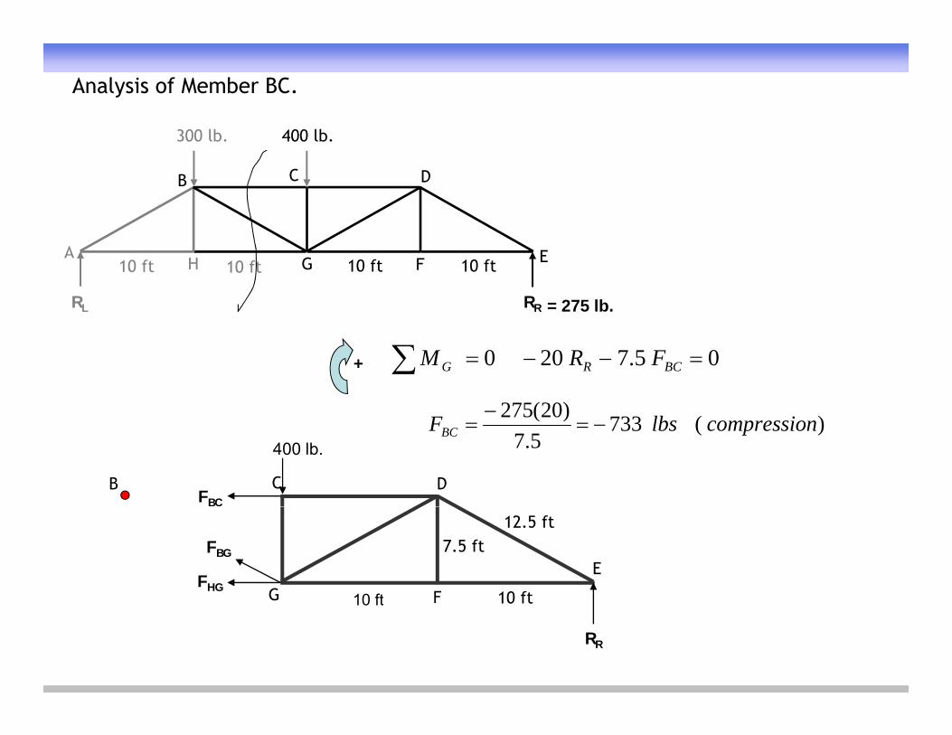
Analysis of Member BC.
400 lb300 lb 400 lb.300 lb.
B C D
10 ft 10 ft 10 ft 10 ftA EFGH
RL RR = 275 lb.
)20(275
+ 05.7200 BCRG FRM
FBC
C DB
400 lb.)(733
5.7)20(275 ncompressiolbsFBC
E
G FFHG
FBG
10 ft
12.5 ft7.5 ft
10 ft
RR
G F 10 ft10 ft
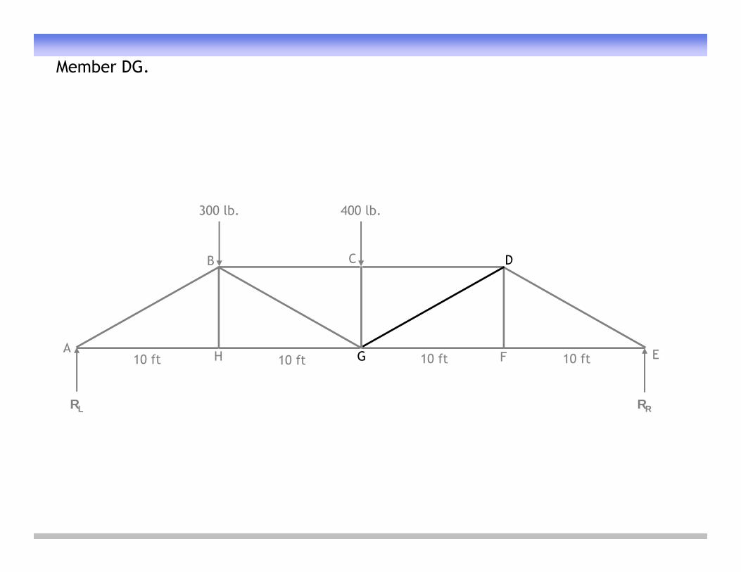
Member DG.
400 lb.300 lb.
B C D
10 ft 10 ft 10 ft 10 ftA EFGH
RL RR
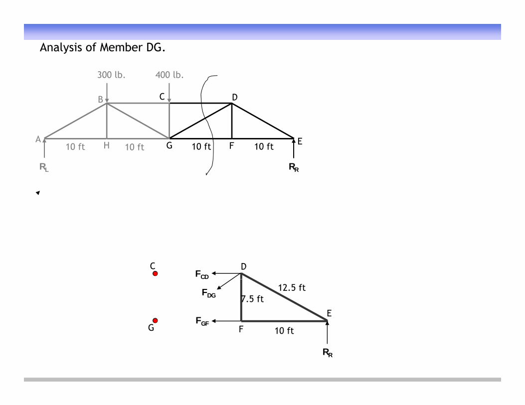
Analysis of Member DG.
400 lb300 lb 400 lb.300 lb.
B C D
10 ft 10 ft 10 ft 10 ftA EFGH
RL RR
FCD
C D
E
G FFGF
FDG
10 ft
12.5 ft7.5 ft
RR
G F 10 ft
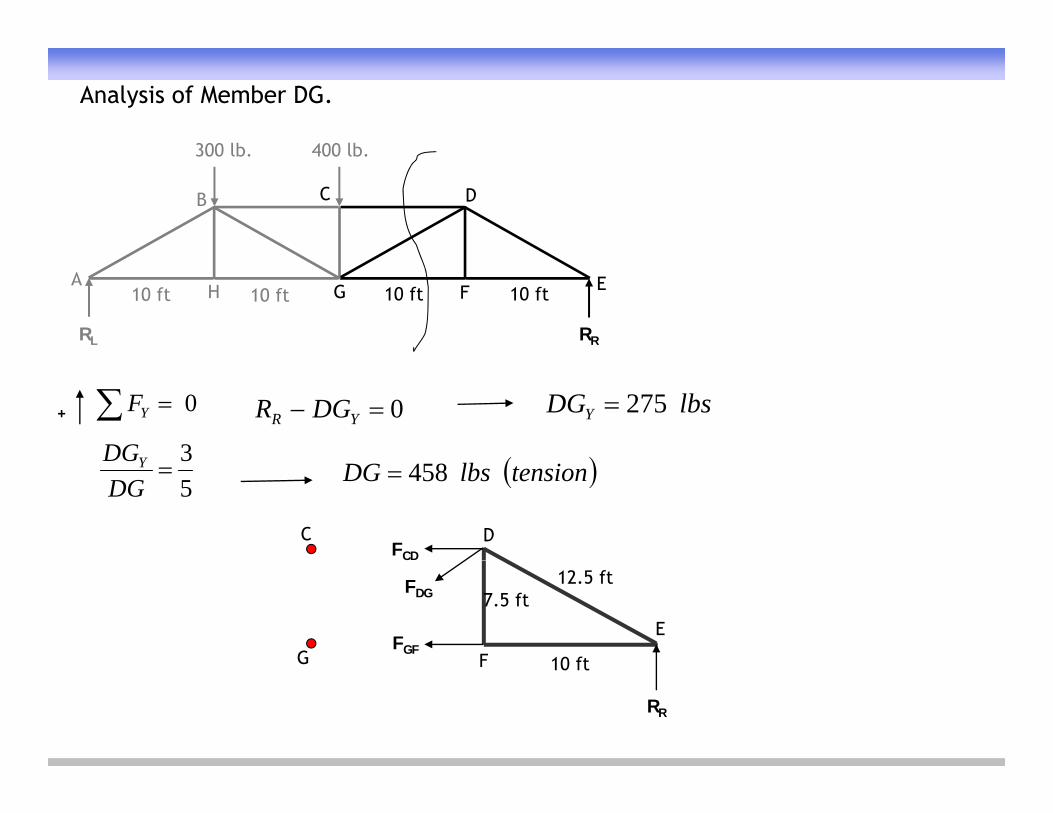
Analysis of Member DG.
400 lb300 lb 400 lb.300 lb.
B C D
10 ft 10 ft 10 ft 10 ftA EFGH
RL RR
0 YF 0 YR DGR lbsDGY 275
3DGY
+
FCD
C D
53
DGDGY tensionlbsDG 458
E
G FFGF
FDG
10 ft
12.5 ft7.5 ft
RR
G F 10 ft
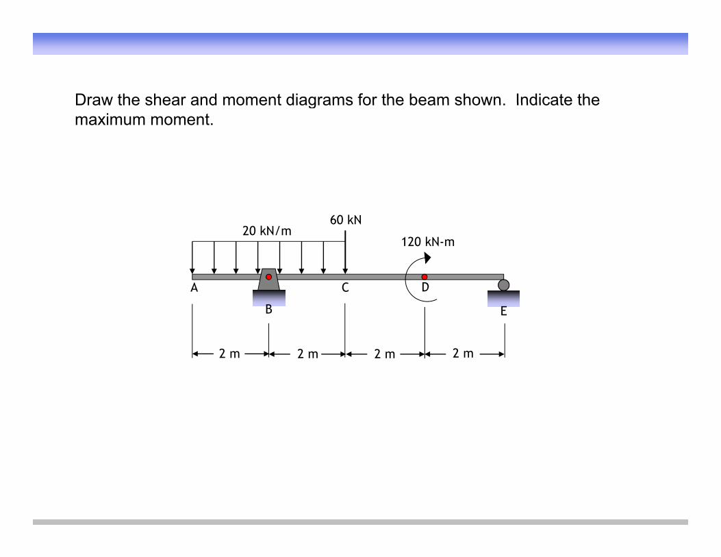
Draw the shear and moment diagrams for the beam shown Indicate theDraw the shear and moment diagrams for the beam shown. Indicate the maximum moment.
120 kN-m20 kN/m
60 kN
120 kN m
A
B
C D
EE
2 m 2 m 2 m 2 m

Draw the Free Body Diagram (FBD)Draw the Free Body Diagram (FBD).(Note: The horizontal force at point B is equal to zero.)
120 kN-m20 kN/m
60 kN
120 kN m
A
FB
C D
FEB FE
2 m 2 m 2 m 2 m

Solve for the reactions at supports B and E
120 kN-m20 kN/m
60 kN
Solve for the reactions at supports B and E.
A
FB = 100 kN
C D
FE = 40 kN
2 m 2 m 2 m 2 m
∑MB = 0 → 60(2) + 120 – 6FE = 0 → FE = 40 kN+
∑FY = 0 → -60 – 80 + FE + FB = 0 → -100 + FB = 0 → FB = 100 kN+

120 kN-m20 kN/m
60 kN
Draw the Shear Diagram
A
100 kN
C D
40 kN
2 m 2 m 2 m 2 m
Draw the Shear Diagram for segment AB.
0 0 V (kN)
kNmkNm 40202
0 0 V (kN)
-40

120 kN-m20 kN/m
60 kN
Show the change in Shear
A
100 kN
C D
40 kN
2 m 2 m 2 m 2 m
Show the change in Shear at B.
0 0
60
V (kN)
kN100
0 0
-40
V (kN)

120 kN-m20 kN/m
60 kN
Draw the Shear Diagram
A
100 kN
C D
40 kN
2 m 2 m 2 m 2 m
Draw the Shear Diagram for segment BC.
0 0
60
20V (kN)
kNmkNm 40202
0 0
-40
V (kN)
120 kN-m20 kN/m
60 kN
Show the change in Shear
A
100 kN
C D
40 kN
2 m 2 m 2 m 2 m
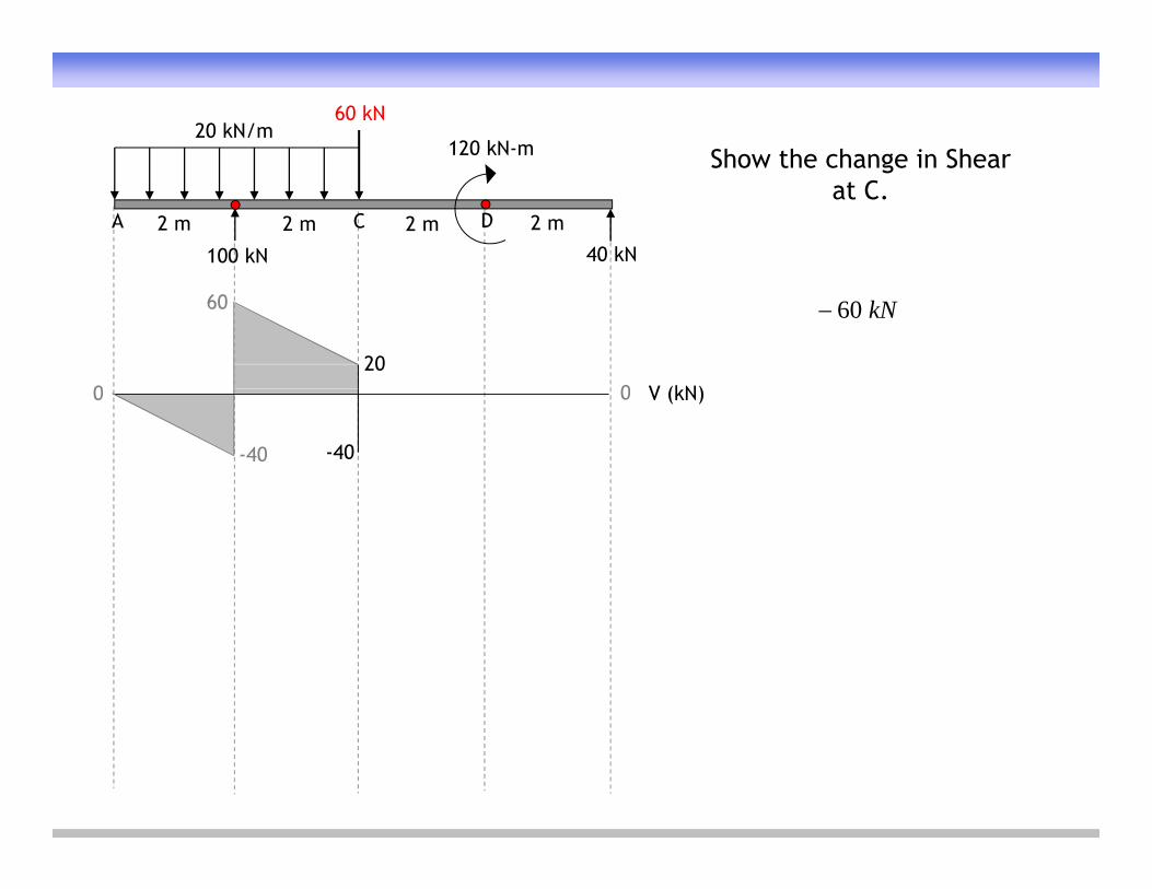
Show the change in Shear at C.
0 0
60
20V (kN)
kN60
0 0
-40 -40
V (kN)

120 kN-m20 kN/m
60 kN
Draw the Shear Diagram
A
100 kN
C D
40 kN
2 m 2 m 2 m 2 m
Draw the Shear Diagram for segment CE.
0 0
60
20V (kN)
kNmkNm 004
0 0
-40 -40 -40
V (kN)
120 kN-m20 kN/m
60 kN
Show the change in Shear
A
100 kN
C D
40 kN
2 m 2 m 2 m 2 m
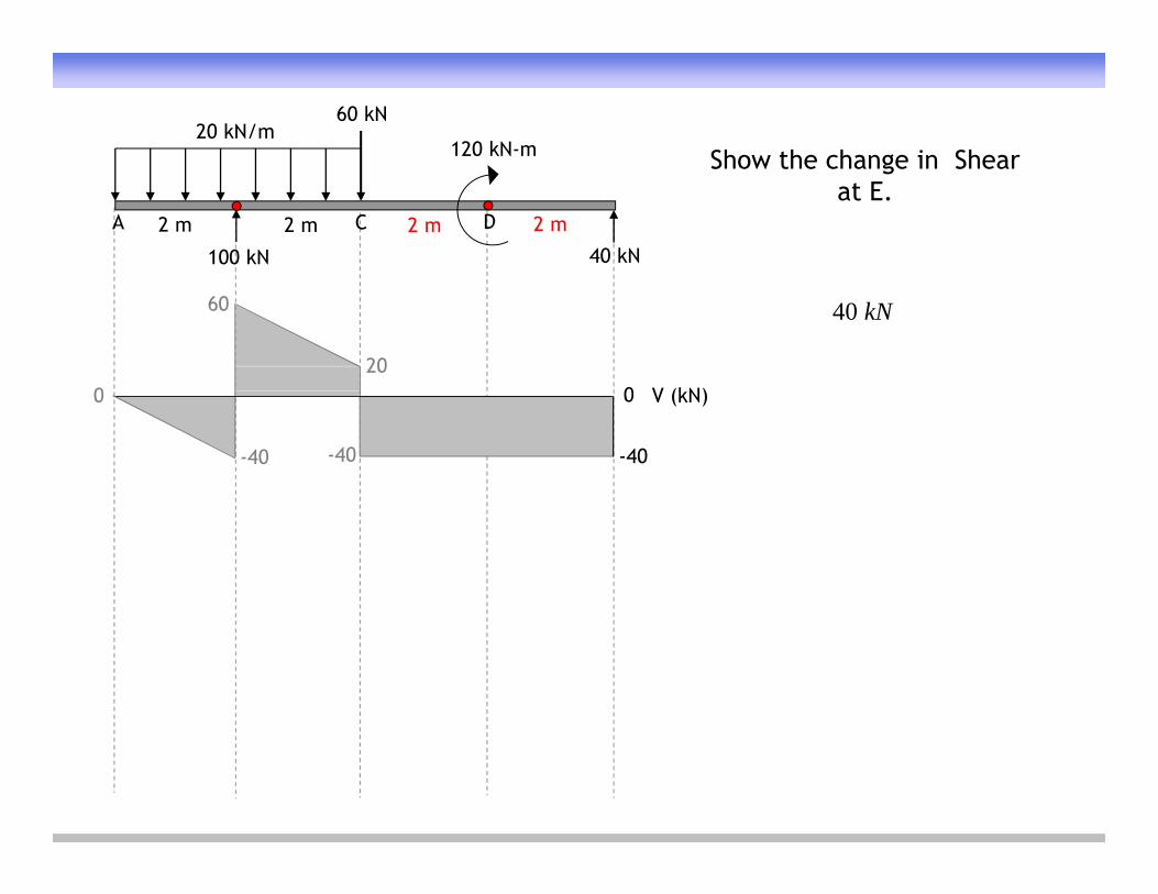
Show the change in Shear at E.
0 0
60
20V (kN)
kN40
0 0
-40 -40 -40
V (kN)

120 kN-m20 kN/m
60 kN
Completed Shear Diagram
A
100 kN
C D
40 kN
2 m 2 m 2 m 2 m
Completed Shear Diagram
0 0
60
20V (kN)0 0
-40 -40 -40
V (kN)
120 kN-m20 kN/m
60 kN
Draw the Moment Diagram
A
100 kN
C D
40 kN
2 m 2 m 2 m 2 m
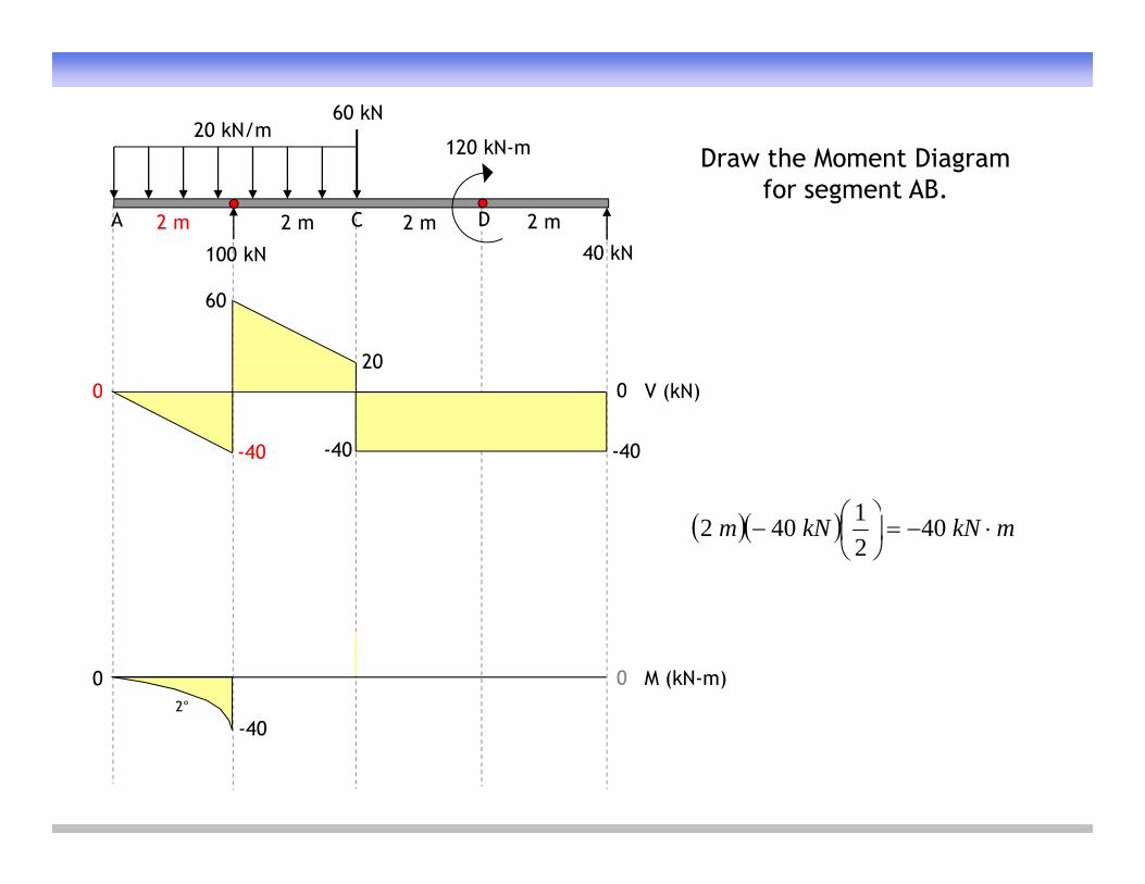
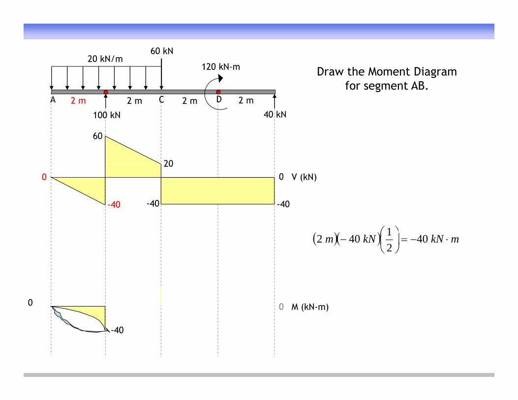
Draw the Moment Diagram for segment AB.
0 0
60
20V (kN)0 0
-40 -40 -40
V (kN)
mkNkNm
40
21402
40
M (kN-m)0 02°
-40
120 kN-m20 kN/m
60 kN
Draw the Moment Diagram
A
100 kN
C D
40 kN
2 m 2 m 2 m 2 m
Draw the Moment Diagram for segment AB.
0 0
60
20V (kN)0 0
-40 -40 -40
V (kN)
mkNkNm
40
21402
M (kN-m)0 0
-40
120 kN-m20 kN/m
60 kN
Draw the Moment Diagram
A
100 kN
C D
40 kN
2 m 2 m 2 m 2 m
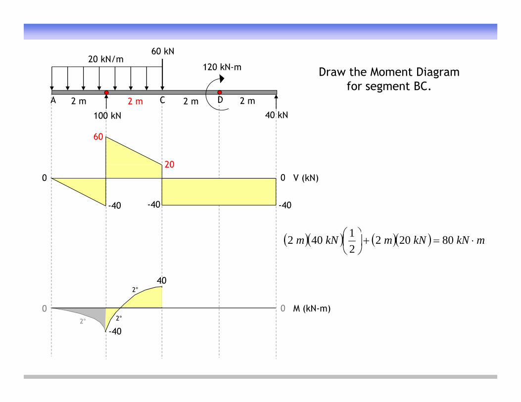
Draw the Moment Diagram for segment BC.
0 0
60
20V (kN)0 0
-40 -40 -40
V (kN)
40
mkNkNmkNm
80202
21402
40
M (kN-m)0 0
40
2° 2°
2°
-40

120 kN-m20 kN/m
60 kN
Draw the Moment Diagram
A
100 kN
C D
40 kN
2 m 2 m 2 m 2 m
Draw the Moment Diagram for segment CD.
0 0
60
20V (kN)0 0
-40 -40 -40
V (kN)
40
mkNkNm 80402
40 40
M (kN-m)0 0
40
2° 2°
2°
-40 -40

120 kN-m20 kN/m
60 kN
Show the change in
A
100 kN
C D
40 kN
2 m 2 m 2 m 2 m
Show the change in bending moment at D.
0 0
60
20V (kN)0 0
-40 -40 -40
V (kN)
40
80
mkn 120
40 40
M (kN-m)0 0
40
2° 2°
2°
-40 -40

120 kN-m20 kN/m
60 kN
Draw the Moment Diagram
A
100 kN
C D
40 kN
2 m 2 m 2 m 2 m
Draw the Moment Diagram for segment DE.
0 0
60
20V (kN)0 0
-40 -40 -40
V (kN)
40
80
mknkNm 80402
40 40
M (kN-m)0 0
40
2° 2°
2°
-40 -40

120 kN-m20 kN/m
60 kN
Completed Moment
A
100 kN
C D
40 kN
2 m 2 m 2 m 2 m
Completed Moment Diagram.
0 0 V (kN)
60
200 0 V (kN)
-40 -40 -40
40
80
40 40
M (kN-m)0 0
40
2° 2°
2°
-40 -40
120 kN-m20 kN/m
60 kN
Find the maximum
A
100 kN
C D
40 kN
2 m 2 m 2 m 2 m
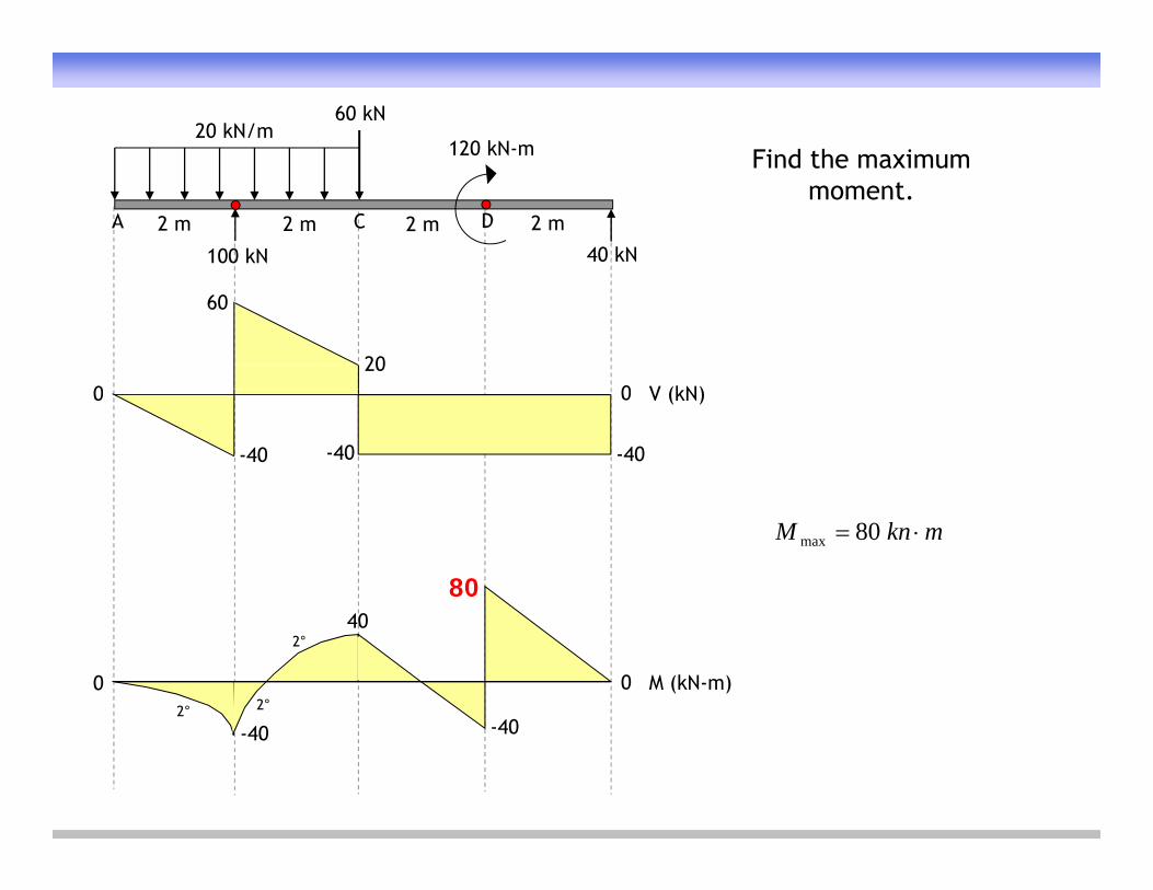
Find the maximum moment.
0 0 V (kN)
60
200 0 V (kN)
-40 -40 -40
40
80
mknM 80max
40 40
M (kN-m)0 0
40
2° 2°
2°
-40 -40

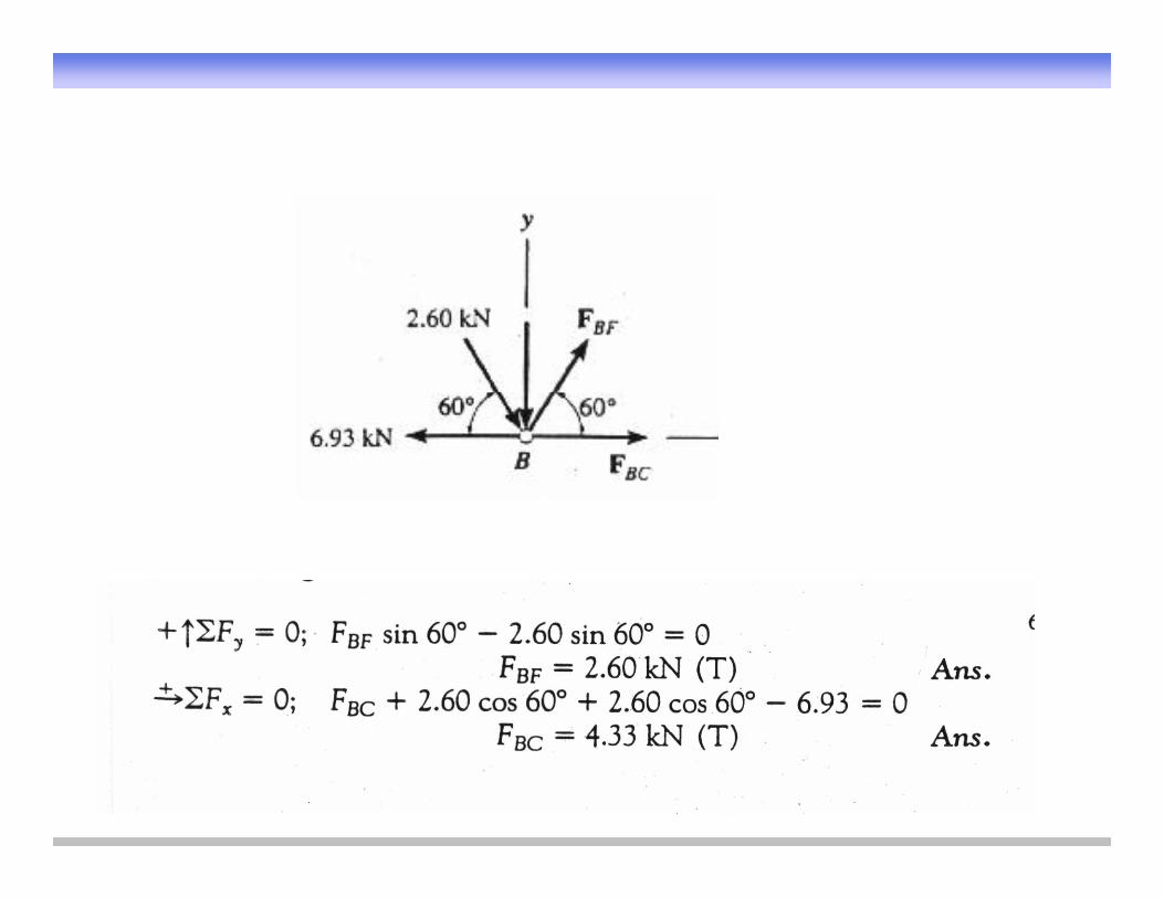
Find the force in the truss members shown.

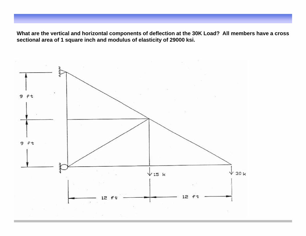
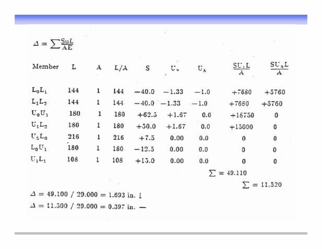
What are the vertical and horizontal components of deflection at the 30K Load? All members have a cross sectional area of 1 square inch and modulus of elasticity of 29000 ksi.

LuS
EA
A C ti l f h b
S = member force with proper sign
A= Cross-sectional area of each member
L= Length of each member
E= modulus of elasticity of materials
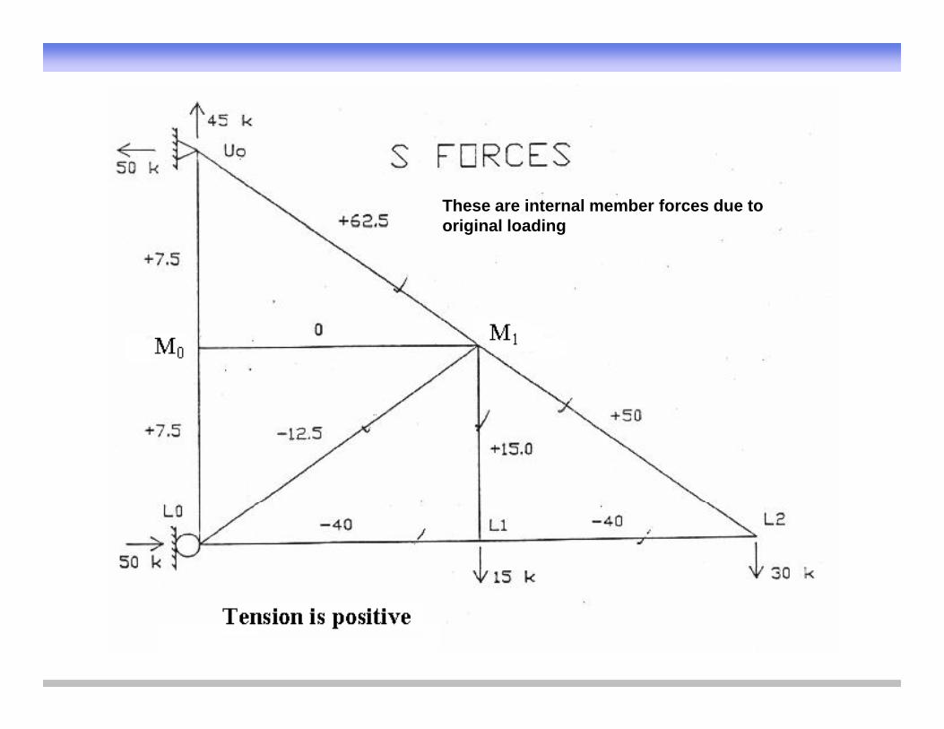
These are internal member forces due to original loadingoriginal loading
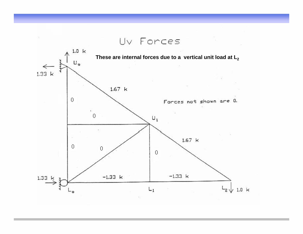
These are internal forces due to a vertical unit load at L2
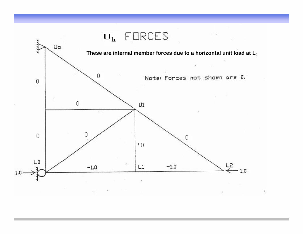
These are internal member forces due to a horizontal unit load at L2
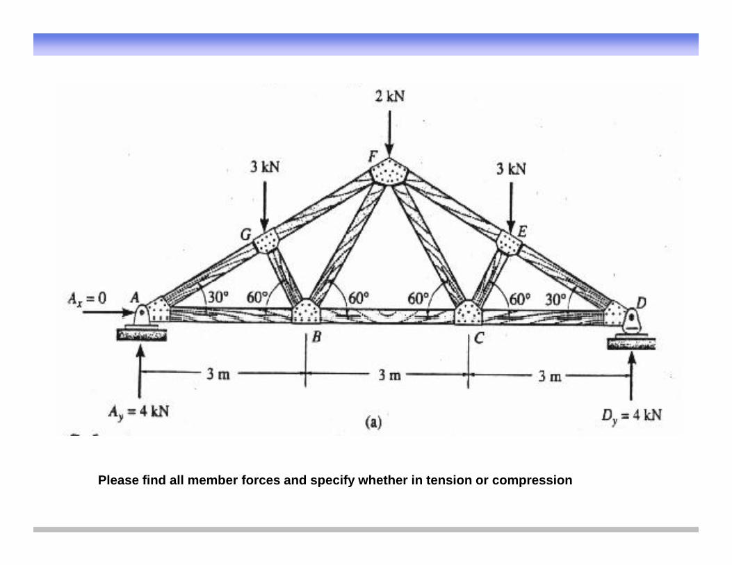
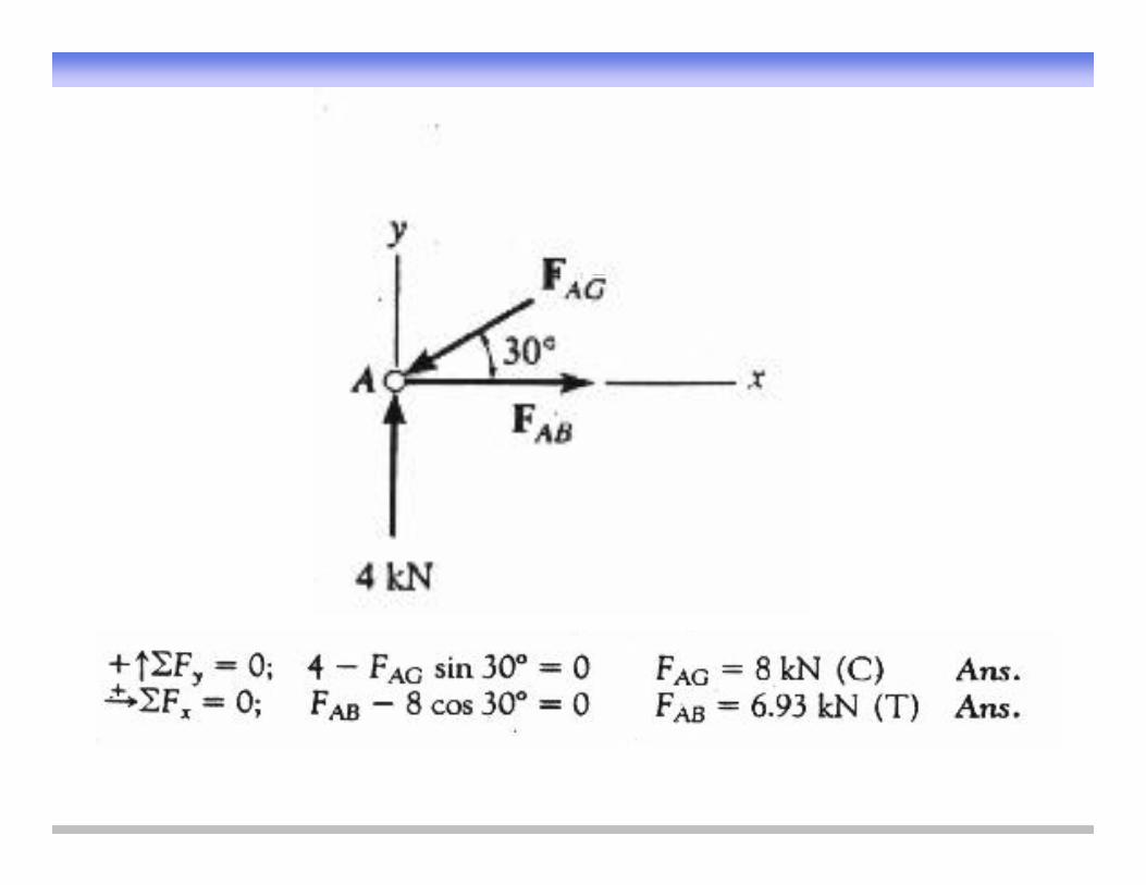
Please find all member forces and specify whether in tension or compression


What are the support reactions for the beam shown?
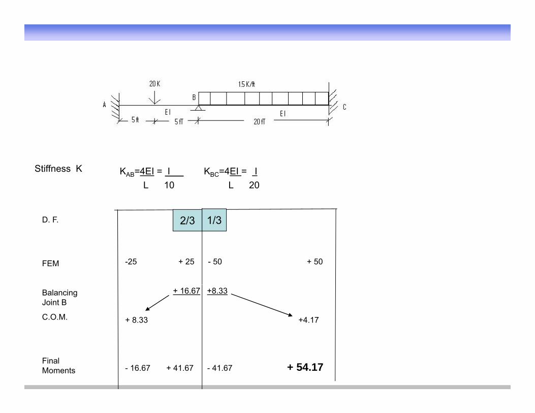
KAB=4EI = I KBC=4EI = I L 10 L 20

Moment Distribution
• 1) calculate the fixed end moments• 1) calculate the fixed end moments
• 2) Calculate distribution of moments at the clamped ends of the b b th t ti f th t j i tmembers by the rotation of that joint
• 3) Calculate the magnitude of the moments carried over to the other ends of the members
• 4) The addition or subtraction of these latter moments to the original ) gfixed ends moments

Fixed End Moments
P
L/2 L/2FEM = PL
8FEM = PL
8
w
L/2
w
FEM= wL2FEM= wL2
12
L
1212
P
L
a b
FEM= Pa2bL2FEM= Pb2a
L2
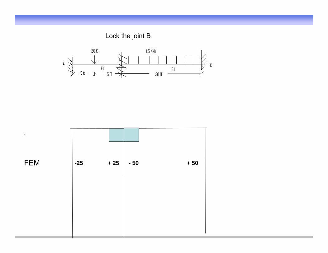
Lock the joint B
.
FEM -25 + 25 - 50 + 50

KAB=4EI = I KBC=4EI = I L 10 L 20L 10 L 20
Di t ib ti F t KDistribution Factor = K_______________
Sum of K for all members at the joint
K
KKDF 1
1
K
KKDF 2
2

KAB=4EI = I KBC=4EI = I L 10 L 20L 10 L 20
Di t ib ti F t KDistribution Factor = K_______________
Sum of K for all members at the joint
KDistribution Factor = KBA_
KBA + KBC
K
KDF 11
K
KKDF 2
2
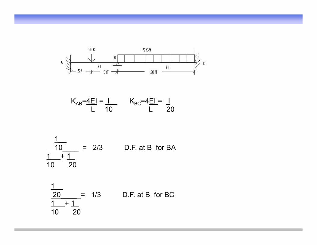
KAB=4EI = I KBC=4EI = I L 10 L 20L 10 L 20
11__10____ = 2/3 D.F. at B for BA
1__ + 1_ 10 20
1__20____ = 1/3 D.F. at B for BC1__ + 1_ 10 20
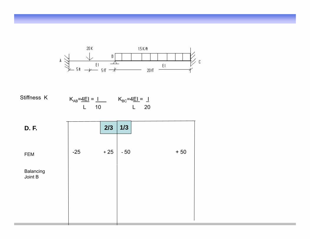
KAB=4EI = I KBC=4EI = IStiffness K
L 10 L 20
2/3D. F. 1/3
FEM -25 + 25 - 50 + 50
Balancing Joint B
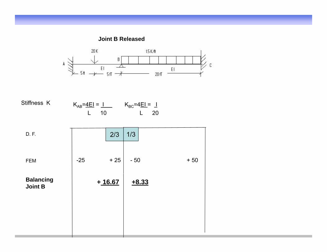
Joint B Released
KAB=4EI = I KBC=4EI = IStiffness K
L 10 L 20
2/3D. F. 1/3
FEM -25 + 25 - 50 + 50
Balancing Joint B
+ 16.67 +8.33
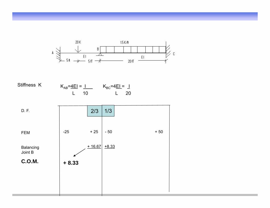
KAB=4EI = I KBC=4EI = IStiffness K
L 10 L 20
2/3D. F. 1/3
FEM -25 + 25 - 50 + 50
Balancing Joint B
C.O.M.
+ 16.67 +8.33
+ 8.33
KAB=4EI = I KBC=4EI = IStiffness K
L 10 L 20
2/3D. F. 1/3
FEM -25 + 25 - 50 + 50
Balancing Joint B
C.O.M.
+16.67 +8.33
+ 8.33 +4.17

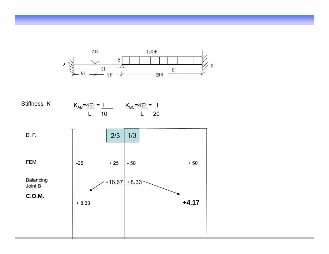
KAB=4EI = I KBC=4EI = IStiffness K
L 10 L 20
2/3D. F. 1/3
FEM -25 + 25 - 50 + 50
Balancing Joint B
C.O.M.
+ 16.67 +8.33
+ 8.33 +4.17
Final Moments - 16.67

KAB=4EI = I KBC=4EI = IStiffness K
L 10 L 20
2/3D. F. 1/3
FEM -25 + 25 - 50 + 50
Balancing Joint B
C.O.M.
+ 16.67 +8.33
+ 8.33 +4.17
Final Moments - 16.67 + 41.67
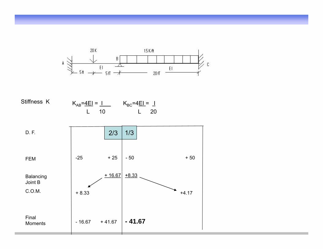
KAB=4EI = I KBC=4EI = IStiffness K
L 10 L 20
2/3D. F. 1/3
FEM -25 + 25 - 50 + 50
Balancing Joint B
C.O.M.
+ 16.67 +8.33
+ 8.33 +4.17
Final Moments - 16.67 + 41.67 - 41.67
KAB=4EI = I KBC=4EI = IStiffness K
L 10 L 20
2/3D. F. 1/3
FEM -25 + 25 - 50 + 50
Balancing Joint B
C.O.M.
+ 16.67 +8.33
+ 8.33 +4.17
Final Moments - 16.67 + 41.67 - 41.67 + 54.17

KAB=4EI = I KBC=4EI = IStiffness K
L 10 L 20
2/3D. F. 1/3
FEM -25 + 25 - 50 + 50
Balancing Joint B
C.O.M.
+ 16.67 +8.33
+ 8.33 +4.17
Final Moments
---------- ------------ ---------- ----------
- 16.67 + 41.67 - 41.67 + 54.17
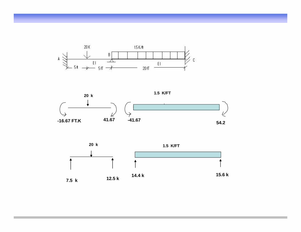
20 k 1.5 K/FT
-16.67 FT.K 41.67 -41.67 54.2
20 k 1.5 K/FT
7.5 k 12.5 k 14.4 k 15.6 k
References
• Hibbeler C R Structural Analysis 3rdHibbeler, C. R., Structural Analysis, 3Edition, Prentice Hall, 1995.
• Chajes, Alexander, Structural Analysis, P ti H ll 1982Prentice Hall, 1982.
Thank You!
• Any Questions?
• Good Luck!