uppaal tron user manual - aalborg universitetpeople.cs.aau.dk/~marius/tron/manual.pdfuppaal tron...
TRANSCRIPT

Uppaal Tron User Manual
Kim G. Larsen, Marius Mikucionis, Brian Nielsen
CISS, BRICS, Aalborg University, Aalborg, Denmark
{kgl, marius, bnielsen}@cs.aau.dk
June 17, 2009
Abstract
Uppaal Tron is an online model-based testing tool for real-time sys-tems. This user-manual documents the implementation features of thetool and could also be used as a reference manual for building test adaptersfor Tron. The reader should be familiar with Uppaal tutorial [1]. Basicknowledge of process control in a shell and programming in C/C++ orJava is assumed.
Contents
1 Introduction 2
1.1 Features . . . . . . . . . . . . . . . . . . . . . . . . . . . . . . . . 21.2 Requirements . . . . . . . . . . . . . . . . . . . . . . . . . . . . . 31.3 Getting Started . . . . . . . . . . . . . . . . . . . . . . . . . . . . 41.4 Relativized Timed Conformance . . . . . . . . . . . . . . . . . . 71.5 Online Test Setup . . . . . . . . . . . . . . . . . . . . . . . . . . 9
2 Test Specification 11
2.1 Properties of the Model . . . . . . . . . . . . . . . . . . . . . . . 122.2 Partitioning of the Model . . . . . . . . . . . . . . . . . . . . . . 14
3 System Adaptation for Testing 17
3.1 Dynamically Linked Library (DLL) Interface . . . . . . . . . . . 183.2 TRON Loaded as Dynamically Linked Library . . . . . . . . . . 213.3 TCP/IP Socket Interface . . . . . . . . . . . . . . . . . . . . . . . 223.4 Sample Java Interface . . . . . . . . . . . . . . . . . . . . . . . . 253.5 Interactive Text Interface . . . . . . . . . . . . . . . . . . . . . . 263.6 Virtual Time Framework . . . . . . . . . . . . . . . . . . . . . . . 28
4 Testing 35
4.1 Command Line Options . . . . . . . . . . . . . . . . . . . . . . . 354.2 Logging . . . . . . . . . . . . . . . . . . . . . . . . . . . . . . . . 384.3 Time Stamping . . . . . . . . . . . . . . . . . . . . . . . . . . . . 394.4 Input Choices . . . . . . . . . . . . . . . . . . . . . . . . . . . . . 48
5 Diagnostics 48

6 Limitations and Workarounds 50
6.1 Modeling . . . . . . . . . . . . . . . . . . . . . . . . . . . . . . . 506.2 Platforms . . . . . . . . . . . . . . . . . . . . . . . . . . . . . . . 50
1 Introduction
Uppaal Tron implementation started as part of Master thesis project andcontinued as part of Ph.D. thesis project by Marius Mikucionis, supervised byKim G. Larsen and Brian Nielsen. The tool is being applied and evaluated inresearch, education and industrial case studies and yet is being improved.
The manual is organized in the following way: we introduce the tool in thissection, discuss the system modeling assumptions, describe the test adapterframework, explain the options and diagnostic messages and outline some futurework. We recommend to get accustomed to Tron through Section 1.3, proceedwith formal and practical framework setup in sections 1.4, 1.5, 2 and use sec-tions 3, 4, 5 as reference manual. Faults and feature requests should be reportedto Uppaal bug tracking system: http://bugsy.grid.aau.dk/cgi-bin/bugzilla/index.cgi.
The following subsections describe features and requirements of Uppaal
Tron, look’n’feel of the tool and how to get started with the demo, finallyexplain the formal concepts used in Tron.
1.1 Features
• Performs conformance testing: the tool checks whether the timed runs ofthe system under test (SUT) are specified in the system model (similarto timed trace inclusion) and no illegal (unexpected, unspecified) timedbehavior is observed.
• The emphasis is on testing the timed and functional properties. Timeis considered continuous, (input/output) events can happen at any real-valued moment in time, but deadlines are constrained by integers (ratio-nals). Test data generation is also possible, but (today) data types andvalue selection are limited by modeling language.
• The specification is an Uppaal timed automata network partitioned intoa model of the system and a model of system’s environment assumptions.The model can be non-deterministic, allowing reasonable freedom for sys-tem implementations, modeling possible/tolerable time drifts, soft timedeadlines.
• Test primitives are generated directly from the model, executed and thesystem responses checked at the same time, online (on-the-fly) while con-nected to the SUT, thus avoiding huge intermediate test suites.
• During testing the tool follows the environment model which can havevarious purposes:
1. fully permissive environment model allows to test full conformance;
2. a specific environment minimizes the testing effort for realistic levelof conformance;
2
3. environment model as use cases guide through functionality of a par-ticular interest;
4. environment model as pre-recorded test runs used to re-execute testsfor debugging or regression testing.
• Uppaal model-checking engine allows efficient and fast timed automatamodel exploration.
• If the environment model is non-deterministic (very often it is) then choicesof inputs and time delays are randomized. So far, early experiments showthat randomization results in the best location, edge and variable valuecoverage as opposed to heuristics based on location, edge, variable valueor combined strategies. This however does not mean that offline test gen-eration techniques cannot be better.
• In general, testing the real-time conformance is undecidable, but underdigitization assumptions it is shown to be sound and complete in a timelimit.
1.2 Requirements
Minimal requirements:
1. Architecture: PC, Intel Pentium compatible.
2. Operating system: Linux (2.6 version recommended) or Microsoft Win-dows NT/2000/XP/2003. Releases are tested on Debian GNU/Linux test-ing/unstable and Windows XP Professional.
Binaries for Sun Solaris (SunOS 5.10) on Sparc can be provided upon request.Optional:
3. Sun Java 5 or 6 Software Development Kit (SDK) for java examples.
4. Apache ANT for java examples.
5. Graphviz [3] utilities for model signal-flow diagrams layouts in pictures.
6. R language and environment for statistical computing and graphics fordisplaying scheduling latency experiment results.
7. GhostViewer gv for displaying PostScript pictures generated from schedul-ing latency experiment.
8. GNU Compiler Collection and GNU make for dynamic library adapters(button example) on Linux.
9. Microsoft Visual Studio 2005 for dynamic library adapters (MSVC buttonexample) on Windows.
Other software assumed:
9. ZIP archive extractor: unzip on Linux and Windows Explorer or WinZIPon Windows.
3

10. Terminal or command line prompt: xterm with bash on Linux, cmd.exeon Windows.
11. GNU tool set (GNU Make from Linux distribution or MinGW or Cygwin)can be used to gain an advantage of automatic build and execution Makefile
scripts included with Tron distribution.
Linux software is available on Debian GNU/Linux via single command:apt-get install sun-java6-jdk graphviz r-base gcc g++ make gv xterm
1.3 Getting Started
The section demonstrates how to use the tool by running a smart-lamp demowith a few mutant examples. Other examples are available through Makefilescripts which can be used with GNU make.
The following steps prepare to use the tool for your operating system.
1.3.1 Installation for Linux
1. Download Uppaal Tron from a Tron webpage. Choose “TRON-V forLinux on Intel PC”, where V is the latest version number. Some versionsare marked as alpha (internal development releases) and beta (previewreleases for general public), which denote the maturity and the featurecompleteness of the release. Please also see the version history on thedownload page.
2. Start terminal or command line window: launch terminal applicationxterm.
3. Check if the proper Java version is installed (i.e. if the environment vari-able PATH is set correctly and GNU Java1 is not in the way): commandjava -version should show something like the following:java version "1.6.0"
Java(TM) SE Runtime Environment (build 1.6.0-b105)
Java HotSpot(TM) Client VM (build 1.6.0-b105, mixed mode, sharing)
4. Unpack Uppaal Tron: enter unzip uppaal-tron-V-linux.zip at com-mand prompt.
5. Go to tron java directory: cd uppaal-tron-V-linux/java.
6. Start another terminal in the same directory: enter xterm &.
1.3.2 Installation for Windows
1. Download Uppaal Tron from a Tron webpage. Choose “TRON-V forWindows”, where V is the latest version number. Some versions aremarked as alpha (internal development releases) and beta (preview releasesfor general public), which denote the maturity and the feature complete-ness of the release. Please also see the version history on the downloadpage.
1Some Linux distributions ship GNU Java as default Java, which is known not towork with Tron SocketAdapter and can be changed to Sun Java by administrator viaupdate-alternatives or galternatives programs.
4

2. Start terminal or command line window: click Start→Run, type cmd.exe
and hit ENTER.
3. Check if the proper Java version is installed (i.e. if the environment vari-able PATH is set correctly: command java -version should show some-thing like the following:java version "1.6.0"
Java(TM) SE Runtime Environment (build 1.6.0-b105)
Java HotSpot(TM) Client VM (build 1.6.0-b105, mixed mode, sharing)
4. Unpack Uppaal Tron: use Windows Explorer or WinZIP to extract.
5. Go to tron java directory: cd uppaal-tron-V-linux/java.
6. Start another command line window in the same directory: enter start
cmd.exe at command prompt.
1.3.3 Smart-lamp Demo
Figure 1 shows the smartlamp test setup. The LightController is the main
grasprelease
levellevel
releasegrasp
Figure 1: Smartlamp setup: LightController (in the middle) connected to Tron
(on the left), level view window and a mouse (on the right).
executable class. The application has two interfaces: for graphical user interface(GUI) and for Tron. GUI shows level of the light as different color shades on alight bulb, adjusts a level bar and draws level history chart. GUI window sendsgrasp and release signals to LightController whenever GUI window is pressedor released with left button of a mouse. The LightController console prints theevents happening in the application. Tron can be attached to LightControllervia SocketAdapter with an equivalent interface of grasp and release as inputsand level as output. Tron window shows the progress of the test run. Thefollowing is a list of commands demonstrating smartlamp application and Tron
tests against it.One can experiment with LightController via GUI without running Tron
by entering the following command line:java -cp dist/smartlamp.jar com.uppaal.smartlamp.Main -M 0
To run Tron test demo in virtual time framework2 against smartlamp followthese steps:
2Mouse clicks are ignored here since the user is not part of virtual time framework.
5

1. Start smart-lamp at one command prompt:java -cp dist/smartlamp.jar com.uppaal.smartlamp.Main -C localhost 8989
-M 0
-C localhost 8989 sets the virtual clock to TCP/IP socket located at localhost port 8989.
-M 0 sets mutant 0 (correct implementation) to be run.
2. Start Tron from another command prompt:../tron -Q 8989 -P 10,200 -F 300 -I SocketAdapter -v 9 LightContr.xml
-- localhost 9999
-Q 8989 creates virtual clock on TCP/IP socket at local host port 8989.
-P 10,200 limits the delay choices up to 10 or 200 time units (this preventschoices of very long delays).
-F 300 tells to pre-compute a symbolic state set for 300 time units intothe future (allows more choices from the near future).
-I SocketAdapter tells to use built-in SocketAdapter.
-v 9 tells to (+1) to print only the progress of testing and (+8) backupthe state set for verdict diagnostics in case the test fails.
LightContr.xml tells to use LightContr.xml file as test specification.
-- localhost 9999 is a parameter to adapter, tells SocketAdapter to con-nect to implementation on TCP/IP socket at local host port 9999.
Run test demo in real time:
1. Start smart-lamp on one command prompt (-C is not used):java -cp dist/smartlamp.jar com.uppaal.smartlamp.Main -M 0
2. Start Tron on another command prompt (-Q is not set):../tron -u 4000,4000 -P 10,200 -F 300 -I SocketAdapter -v 9 LightContr.xml
-- localhost 9999
Note that GUI mouse clicks can be used to alter the behavior of LightControllerin real time, hence introducing behavior mutations which may be sensed byTron. See also Section 6 if Tron reports test failures on mutant M0 in realtime.
1.3.4 Smart-lamp Mutant Exercise
For the smart-lamp mutant exercise you need the model LightContr4.xml, andthe following command lines to start Tron and the controller:../tron -Q 8989 -P 10,200 -F 300 -I SocketAdapter -v 10 LightContr4.xml --
localhost 9999
java -cp dist/smartlamp.jar com.uppaal.smartlamp.Main -C localhost 8989 -M
0
There are two built-in faulty mutants controlled by -M option: -M 1 and -M
2.The easiest way to create your own mutants is to modify the existing Light-
Controller source and add mutants in the style of the existing mutants (a flag
6

indicates what mutant to run, and use if (mutantID) statements to enable thefaulty code. One typically needs to edit the com/uppaal/smartlamp/SmartLamp.javaand/or com/uppaal/smartlamp/Dimmer.java files in src directory. Remember torecompile the smartlamp once edited: ant clean jar
1.3.5 Offline Generated Tests
We recommend executing your preset input sequences using Tron by modelingthe test input/output sequence as a timed automaton and by replacing the envi-ronment with this automaton. Depending on desired timing choices Tron canbe run in random, eager, lazy or bounded delay mode. An example is providedin LightContr4.xml (Template: LightCov and Envy Closure, see system sectionof the model). Start Tron as described below, try eager and other delay options:../tron -Q 8989 -P eager -F 300 -I SocketAdapter -v 8 LightContr4.xml -- localhost
9999 silent
../tron -Q 8989 -P 10,200 -F 300 -I SocketAdapter -v 10 -w 20 LightContr4.xml
-- localhost 9999
../tron -Q 8989 -P random -F 300 -I SocketAdapter -v 8 LightContr4.xml -- localhost
9999 silent
../tron -Q 8989 -P lazy -F 300 -I SocketAdapter -v 8 LightContr4.xml -- localhost
9999 silent
1.3.6 Create Your Own Smart-lamp
Here you have to create both a model and an implementation. It is easiest tostart with the template given in onOffLight.xml and OnOffLightController.java:java -cp dist/smartlamp.jar com.uppaal.autoofflamp.Main -C localhost 8989 -M
0
../tron -Q 8989 -P 10,200 -F 300 -I SocketAdapter -v 10 onOffLight.xml -- localhost
9999
1.3.7 Create Your Own Implementation
The package com.uppaal.dummy includes a minimal dummy implementationthat behaves like dummy.xml specification. TestIOHandler takes care of in-put/output translation and communication, where DummyInterface declareswhat kind of input methods Dummy implementation can handle and DummyListener
interface declares what output methods are available. Once the source of thedummy is modified, the new implementation can be compiled by invoking ANTrule ant clean jar which reads build.xml script, cleans the old byte code,compiles and packages a new jar package in dist directory. The resulting pack-age can be optimized and obfuscated with ProGuard by invoking ant clean
dist.
1.4 Relativized Timed Conformance
Tron uses rtioco as implementation relation to specification in order to evalu-ate the correctness of a test experiment and to determine the test verdict. rtioco
is an extension to tioco which in turn has roots in ioco by Jan Tretmans [].Explicit handling of environment assumptions is an essential feature which dis-tinguishes rtioco from other timed conformance variations and still compatible
7

with ultimate qualities of tioco . The environment assumptions give additionalinformation about specific kinds of implementation behavior and help tester tofocus on features of interest, closer reflect reality and hence reduce testing costs.
Definition 1 augments the formal definition of rtioco [7] with engineeringinterpretation, which means that implementation p conforms to specification s
within the environment e if and only if the observations from test executionon 〈e, p〉 are always included in possible observations described by specification〈e, s〉 while running all possible traces of environment e.
Definition 1 Relativized timed input/output conformance relation for inputenabled timed input/output labeled transition systems p, s ∈ S and e ∈ E:
p rtiocoe sdef= ∀σ ∈ TTr
(
e)
.Out(
〈e, p〉 after σ)
⊆ Out(
〈e, s〉 after σ)
(1)
where:
S and E are the sets of timed input/output labeled transition systems that arecompatible with respect to observable inputs and outputs: S observableoutputs synchronize with observable inputs of E and vice-a-versa,
p,s and e are initial states of implementation under test, specification andenvironment respectively,
TTr(
e)
is a set of timed input/output traces of e,
〈e, p〉 and 〈e, s〉 are parallel compositions of p and e, and s and e, respectively,where processes synchronize on observable input/output action transitions,
〈e, p〉 after σ means executing an observable trace σ on implementation p withinenvironment e and returning the end state(s) of the system,
〈e, s〉 after σ means evaluating an observable trace σ on specification s withinenvironment e and returning a set of possible system specification states,
Out(
states)
return the list of possible output action and/or delay observations.
Notice that the definition mentions environment twice: firstly composed withimplementation (real physical entity) and secondly composed with specification(virtual abstraction or modelled entity). Formally (and ideally) these environ-ments are the same (hence only one e is needed), but in practice it is the tester’sresponsibility to transform the modelled environment into the real physical en-tity, which means providing adapters with physical interface to implementationand behaving like environment model.
Let us examine possible cases and see why this relation is good for definingthe correctness of timed behavior in black-box testing:
1. Definition is provided for timed labeled input/output transitions, whichmeans that it is applicable to a broad class of timed systems (e.g. hybridsystems), not just the ones modelled by timed automata and is indepen-dent of modelling formalisms. Definition also does not go deeper nor dwellsabout the structure of p, s and e processes: no assumptions about themare made, high-level abstract specifications s and e are possible allowingall kinds of non-determinism, does not measure the state of p directlyallowing black-box testing, s, e and p can be composed of many parallelprocesses which allow modular designs of the system and the specification.
8

2. Follows common intuition that outputs should be observed as they aredescribed in the specification: neither too early nor too late if allowed atall. If tester observes delay δ ∈ R≥0 followed by output o ∈ Aout fromimplementation after trace σ then it means δ ∈ Out
(
〈e, p〉 after σ)
and
o ∈ Out(
〈e, p〉 after σδ)
. The tester should compute the largest delay d
such that d ∈ Out(
〈e, s〉 after σ)
and check whether δ ≤ d:
• if δ ≤ d is false then it means that specification did not allow todelay for δ times, and p does not conform to s. However, if o ∈Out
(
〈e, p〉 after σd′)
for some d′ ≤ d, then it means that output isallowed but observed too late (later than required after d′).
• if δ ≤ d is true then o ∈ Out(
〈e, p〉 after σδ)
has to be checked:
– if true then output o is allowed and should be appended to σ
trace
– if false then output o is not allowed. However if there is d′ suchthat o ∈ Out
(
〈e, p〉 after σd′)
and d′ > δ then it is likely that o isallowed but is observed too early (earlier than delay d′). Anotherpossibility is that there exists d′′ < δ after which o is allowed,then observation can be classified as o is allowed but observedtoo late (later than after delay d′′).
3. Definition allows incremental test trace construction, see the output ob-servation discussion above which also holds for input events.
4. Relation considers only the traces that are possible in environment e whichgives us the power to test the selected timed behavior. The input enable-ness of e guarantees that any output produced by p or s is accepted andnot refused, hence does not influence the correctness. There are two in-teresting extreme cases of environments:
(a) Universal environment eU which allows all observable timed traces:TTr
(
eU
)
= (Ainp ∪ Aout ∪ R≥0)∗. Then p rtiocoeU
s coincides withtimed trace inclusion and is equivalent to p tioco s.
(b) Silent environment eS which does not allow any inputs but merelyconsumes outputs and lets the time pass: TTr
(
e)
= (Aout ∪ R≥0)∗.
This is the same as Ainp = ∅ where tester is allowed only to observethe behavior of implementation. Such activity is equivalent to passivemonitoring of the system.
In theory black-box timed testing is undecidable due to (timed trace) lan-guage inclusion checking problem, however in [7] the online test generation al-gorithm for real-time systems is shown to be sound and also complete (exhaus-tive) under input-enableness, observability and digitization assumptions if givenenough time. The assumptions are important only for theoretical completenessand can be relaxed in practice.
1.5 Online Test Setup
We consider closed systems, where implementation together with its environ-ment can be isolated from the rest of the world. Figure 2a shows typical system
9

setup during the system deployment: environment is a plant that needs to besteered and controlled, and implementation is a software/hardware controllertaking inputs from the sensors embedded in the environment and producingoutput to actuators influencing the environment. Notice that we take the per-spective of the controller or implementation when talking about inputs andoutputs.
Implementation
(plant controller)
Environment
(plant under control)
input
outputActuators
Sensors
(a) System during deployment.
Tester AdapterImplementation
under test
input"in"
"out" output
Environment
(b) IUT’s perspective during testing.
Tester Adapter Implementation
input"in"
"out" output
Environment Implementation Under Test
(c) Tester’s perspective during testing.
Figure 2: Implementation during deployment and testing.
In Figure 2b we replace the environment, sensors and actuators with a testerand a test adapter in order to test such controller. In generic test setup theadapter translates abstract input messages into physical actions and recognizesphysical outputs and encodes them into abstract messages understood by thetester. The adapter is always implementation specific, moreover adapter imple-mentation may also contain faults, hence we arrive to Tron test setup shownas tester’s perspective in Figure 2c where the adapter is shifted to be a part ofthe implementation under test. We rely on the assumptions that adapter is fastenough to mimic sensors and actuators and tester is fast enough to emulate theenvironment and therefore provide fair tests.
The system model provided as test specification should also reflect the phys-ical setup and partitioning of component-processes as shown in Figure 2c. Theinputs are controlled by the tester and the outputs are controlled by the imple-mentation. While modelling the IUT requirements and environment assump-tions is rather straightforward, the model of an adapter is often overlooked.In Tron framework we follow the semantics of time automata specificationdefined as labelled transition systems, where events (edge-transitions) happenatomically and instantaneously. Therefore we also treat an event as a singlepoint in time and space, where the time defines when the event happened (rela-tively to the start of testing), space-location defines a component of the systemand action label identifies an edge of the component process. Notice that asimple electronic signal traveling via wire corresponds to a series of events atdifferent locations of the wire. Ultimately, physical reality does not allow mea-suring location and time of event precisely (precise timing cannot be measuredif the location is known precisely and precise location cannot be measured atprecise timing), moreover it is not possible nor desired to provide models at suchdetailed level, hence a reasonable abstraction is needed which still captures theimportant details.
First, we propose to split input/output action into two events: 1) wheninput action is sent by the tester (output action is sent by implementation)
10

and 2) when input action is received by implementation (output action receivedby tester); this will make sure that input and output actions can pass eachother as in asynchronous distributed systems. Second, model the adapter as anevent buffer. One size buffer is a cell shown in Figure 3a and n-size buffer is aparallel composition of n cells composed in a sequence as in Figure 3b. Based
event[i]!x[i]=0event[i−1]?
idle
in_transitx[i]<=delay
(a) Cell.
event[i]!x[i]=0event[i−1]?
idle
in_transitx[i]<=delay
event[i]!x[i]=0event[i−1]?
idle
in_transitx[i]<=delay . . .
event[i]!x[i]=0event[i−1]?
idle
in_transitx[i]<=delay
i == 1 i == 2 i == n
(b) n-size buffer.
Figure 3: Buffer automata for the adapter model, where x[i] is a clock.
on a concrete value of delay and on assumptions on how many actions canbe generated at the same time, one can find minimal buffer size n and using[6, 5] techniques prove that such buffer is a correct abstraction of a physical one(down to atomic details).
While the input part of adapter is important for the implementation input-enableness assumptions and reflecting the possible delay in signal, the outputpart of adapter is merely delaying the output but has severe performance penaltyif the buffer is large, hence should be kept as simple as possible.
Tron uses interval time-stamping in order to solve the problem of precisetime-measuring: the action is time-stamped at the tester’s interface to adapterand the time-stamp is converted to model time interval, whose bounds are theclosest integers to measured time-stamp. This reflects our notion that we don’treally know when the event actually happened, but somewhere in the interval,and allows us to compute an over-approximation of actual behavior of the sys-tem. The over-approximation enforces the principle “behavior is correct unlessproved otherwise” and it does allow some non-conforming behavior to pass thetest, but we think that it is reasonable given that the observability (ability tomeasure the timings) and controllability (ability to feed inputs at precise timing)are not perfect as one could expect in theory.
2 Test Specification
A Tron test specification consists of the following items:
• Uppaal model containing requirements for environment and IUT pro-cesses,
• input/output channel interface between environment and IUT processes,
• model time unit definition and
• amount of time dedicated for testing.
11

roomcompressor
sensorcontrollerswitch
turn_off()turn_on()
temp(T)
under testimplementationenvironment
Figure 4: Fridge model setup.
We will use the fridge system from Figure 4 as a running example to demon-strate how typical system model is composed for testing using Tron. The fridgesystem consists of five processes: room, sensor, controller, switch and compres-sor. The room process controls the room temperature of the fridge: a sampleroom automaton is displayed in Figure 5b. The sensor process identifies whetherthe sensed temperature is High, Med or Low, see the timed automaton in Fig-ure 5c. The controller process is controlling whether the compressor should beturned On or Off via shortcutting a switch, see Figure 5d. The switch processis relaying the signal to compressor by turn on and turn off like automaton inFigure 5e. The compressor process is responsible for notifying the room aboutthe change of conditions in the fridge, i.e. if compr is true then the heat is takenaway by the circulating liquid and if false then the heat is leaked into the fridge,see Figure 5f and Figure 5b. Assume that we want to test the software runningin the controller component of our fridge system. The only way to connect tocontroller is through the sensor and switch interfaces as there is no “direct”connection with the controller process. Notice that the sensor and the switchintroduce the communication latency3, which is reflected by the upper bound ofd time units in sensor and switch automata. Hence, the controller, the switchand the sensor models belong to the IUT requirements as there is no way toseparate them. The rest of the processes (the room and the compressor) belongto assumptions about environment of IUT.
2.1 Properties of the Model
Tron allows non-determinism in the model. For some models the resultingstate space can even be beyond the verification. For example, the requirementsfor the controller in Figure 5d are non-deterministic in two ways:
1. in action: the location up is allowed to be reached after Med or Highactions. Similarly the location dn can be reached from on by any of Lowor Med actions. Modeling that the IUT is allowed to implement eithersequence.
2. in time: the controller may stay in locations up and dn for any timeduration up to r time units. Modeling allowed reaction time tolerance.
Moreover the communication latency in adapter adds even more unavoidable(concurrency) non-determinism to the IUT requirements. Similarly the envi-ronment processes can also be non-deterministic, e.g. the room is allowed to
3Even tiniest latency is relevant as it models the concurrent nature of independent inputand output signals.
12

// IUT requirements:const int r=15;int sensed=0;clock x, sn;chan High, Med, Low, On, Off;// observable ( test interface ) part :chan temp; // inputsint T=0; // data bound to inputchan turn on, turn off ; // outputs// environment assumptions:const int p=5;const int s=30;const int d=1;clock sw, rm;bool compr;
(a) Global declarations.
!compr and rm>p
comprand rm>p
temp! temp!
rm<sT=T+1,rm=0
T=T−1,rm=0
(b) room
High!
temp?
Med!
Low!
sensed=T,sn=0
sensed<=0
sensed>5
sensed<=5and sensed>0
sensingidle
sn<dsn=0
sn=0
sn=0
(c) sensor
Med?Med?
Low?High?Low?
off
High?Low?
High?
Med?
Off!
Low?
x:=0
x:=0
x:=0
x:=0
x:=0 up
on
dn
x:=0
x:=0
x<=rx<=r
x:=0
Med?
Med?
High?
Med? On!
(d) controller
sw<d
sw<d
disconnecting
connecting
idle
turn_off!Off?
turn_on!On?
sw=0sw=0
sw=0sw=0
(e) switch
turn_off?
compr=trueturn_on?
compr=false
(f) compressor
Figure 5: Model of the refrigeration system, fridge.xml.
update the temperature in any periods of time between p and s time units. Thesensor automaton makes sure that the input (temperature changes) will alwaysbe accepted by IUT part if offered no more often than d time units intervals.Similarly the compressor automaton can accept the output at any time.
The more non-deterministic environment model is, the more discriminativepower it has. Generic environments which allow any input fed at any time arethe most discriminative, although they are not always practical in testing. Ourroom and compressor automata model a more realistic environment, where theroom temperature is responsive to the state of compressor. We can also replacethe room and the compressor by an automaton modelling a concrete test casewhich could drive the system into interesting states.
The IUT model should be at least weakly input enabled (ability to consumeany input at any time) although there are no precise guidelines on how strictlythis requirement should be enforced and Tron will try to obey the assumptionsin IUT model. The environment model is not required to be input enabled (toaccept any output at any time from IUT) and the verdict inconclusive will begiven if the environment state can not be updated with unexpected IUT output.
13

2.2 Partitioning of the Model
Input/output channels partition the Uppaal model processes and variables intoenvironment and implementation. The goal of partitioning is to ensure that thesetup of real environment and IUT is correctly reflected in the model and onlythe observable channels are used for communication between the two. Theduration of model time unit specifies how much of the real world time in mi-croseconds elapses when Uppaal clock gets incremented by one. The maximumamount of desired testing time is specified by “timeout for testing” in modeltime units (one Uppaal clock increment).
Currently the procedure for partitioning the system is by specifying in-put/output channel interface. The partitioning should be consistent (no pro-cess/variable should be assigned to both environment and IUT) and complete(all processes should belong to either environment or IUT). Given a user definedset of observable I/O channles, Tron attempts to partition a model of a wholesystem by iteratively applying the following rules:
• Events on input/output channels are observable and events on other chan-nels (that are not declared as inputs/outputs) are non-observable or in-ternal.
• Internal channel belongs to environment if it is used by an environmentprocess. Respectively, internal channel belongs to IUT if it is used byIUT process. The model is inconsistent and cannot be partitioned if theinternal channel is used by both environment and IUT.
• Process belongs to the environment if it uses the internal environmentchannel respectively. Respectively, process belongs to IUT if it uses theinternal environment channel.
• A variable belongs to the environment if it is accessed by an environmentprocess without observable input/output channel synchronization. Re-spectively, a variable belongs to the IUT if it is accessed by IUT processwithout observable input/output channel synchronization. A variable isnot categorized (allowed to be either) if accessed consistently during ob-servable input/output channel synchronization.
• Process belongs to environment if it accesses environment variable withoutobservable channel synchronization. Respectively, process belongs to IUTif it accesses IUT variable without observable channel synchronization.
If the partitioning is not consistent or incomplete Tron will complain withwarnings.
Tron also uses the partitioning to identify environment invariants from IUTinvariants for accurate environment emulation, where otherwise all invariantswould be treated globally (according to Uppaal timed automata semantics)and IUT invariant would force Tron to take action before it is violated. Wheninterface configuration is done, Tron outputs the list of environment processeswhose invariants are used in environment emulation.
In practice to help getting the partitioning accepted by Tron, the -i dot
option can be used to produce a decorated signal flow diagram that can bevisualized by graphviz [3] tools. This option expects I/O channels fed by the
14

following EBNF rule:"input" (channel)∗ "output"(channel)∗
The option will also accept the text following the preamble rule from Figure 16(all parameters in parenthesis are ignored). The end of the input stream isdetected by keywords precision or timeout, or simply by end-of-file signal.The output stream can be laid-out and visualized graphically by dot4 [2]. Thediagram shows how processes are communicating similarly to UML deploymentdiagram [] except that associations are displayed as arrows indicating the direc-tion of signal flow. Diagrams have the following legend:
b represents a process.
f represents a data variable (clock or integer).
& represents an internal channel.
&F represents an observable channel.
→ represents a signal flow: from a process to a channel – the process is trans-mitting on the channel, from a channel to a process – the process is re-ceiving on channel, from a process to a variable – the process is updat-ing (writing to) the variable, from a variable to a process – the processis reading value of the variable. The transmitting and updating arrowsare bold. The label above arrow enumerates the simultaneous channelsynchronizations during data update, dash denotes an update without achannel synchronization (internal transition).
blue items (processes, variables and channels) belong to IUT.
green items (processes, variables and channels) belong to environment.
gray items may belong to either IUT or environment. Gray data variables aregood candidates for value passing over channel.
red items could not be partitioned consistently or have some suspicious prop-erties (like variable is updated but is never read).
The error stream is allocated for warnings and errors. The verbosity of errorstream is controlled by -v option: 0 (none), 1 (only errors), 2 (only errors andwarnings), 3 (diagnostic trace of partitioning with errors and warnings).
Example. Suppose the system model is provided in fridge.xml file andthe test interface is specified in fridge.trn file shown in Figure 6a. Then thepartitioning image fridge.eps and partitioning diagnostics can be obtained bythe following bash command line:
tron fridge.xml -i dot -v 3 < fridge.trn | dot -Tps -o fridge.eps
The command executes Tron with system model fridge.xml, asks for parti-tioning in dot format (-i dot), sets the error stream verbosity level to all diag-nostics (-v 3), feed the interface description as input stream from fridge.trn
file. The output stream with graph data is redirected to dot process which isasked to produce PostScript (-Tps) image of the graph layout and write it tofridge.eps file (-o fridge.eps). The user should observe diagnostics in the
15

input temp(T);output turn on(),
turn off ();precision 1000;timeout 10000;
(a) fridge.trn
Inputs: tempOutputs: turn_off, turn_onAdding ”room” using ”temp” by rule ”transmitters on
input channels belong to Env”Adding ”compressor” using ”turn off” by rule ”receivers
on output channels belong to Env”Adding ”sensor” using ”temp” by rule ”receivers on input
channels belong IUT”Adding ”High” because of ”sensor” by rule ”internal
channel belongs to IUT if it is used by IUT”Adding ”Low” because of ”sensor” by rule ”internal
channel belongs to IUT if it is used by IUT”
(b) Diagnostics sample.
Figure 6: The files in automatic model partitioning
error streams whose content is similar to Figure 6b. The first two lines of Fig-ure 6b show the input and output channels separated by comma. The later linesshow which items were partitioned using a particular rule. If the partitioning isnot successful, the user should look at the diagnostics, find the first line whereprocess, channel or variable was assigned to wrong side and fix the problem inthe model. Figure 7 shows the sample image of the partitioning. The image
swit
ch
sw
(Off,
On,
turn
_off,
turn
_on)
turn
_off
turn
_on
sen
sor
Hig
hL
ow
Me
dse
nse
d(tem
p)
sn(Hig
h,Lo
w,M
ed,te
mp)
con
tro
ller
Off
On
x
(Hig
h,Lo
w,M
ed,O
ff,O
n)
(-)
(-)
(-)
(-)
com
pre
sso
r
tem
p
roo
m
rm(tem
p)
T
(tem
p)com
pr
(turn
_off,
turn
_on)
(-)
(-)
(tem
p)
(tem
p)
Figure 7: Decorated signal flow diagram (fridge.eps) of the system model.
might have different layout each time it is generated as dot gets different initialrandom seed.
4The other utilities can also be useful, but dot usually gives the best results as quality ofthe layout depends on the minimization of edge crossings (NP-hard problem).
16

3 System Adaptation for Testing
The test system developer must provide a test adapter in order to adapt thesystem for testing. The adapter is responsible for translating symbolic inputdescriptions into concrete physical input actions, recognizing physical outputsand translating them back to symbolic output representations that testing toolunderstands. The Tron driver implements Reporter interface which is used toconfigure test interface (define observable inputs and outputs in the model) andreport the outputs detected by adapter. The TestAdapter interface is used byTron driver to feed the inputs. Figure 8 shows the interface between Tron andthe test adapter: the Tron driver exports a Reporter interface which is refer-enced by adapter component and adapter is exporting a TestAdapter interfacewhich is referenced by driver component. The connection establishment, testinterface configuration and physical I/O are adapter implementation specific.
UPPAALengine
adap
ter
IUT
dri
ver
UPPAAL TRONReporter
TestAdapter
inputs
outputs
configuration
Figure 8: Adapter API and physical interface.
The adapter is specified by -I name command line option where name isthe name of the adapter. If the adapter is provided in a dynamically linkedlibrary then the name refers to the library file name. The adapter may supportcommand line arguments too: the adapter parameters are specified at the endof Tron command line starting with double dash --, otherwise the adapter willget an empty list of arguments.
Table 1 summarizes advantages and disadvantages of adapter APIs. TextualAPI (Section 3.5) is probably the easiest way to communicate with Tron whichdoes not require any software development skills except knowledge of the traceformat, however it is slow due to continuous I/O stream parsing and encoding.DLL API (Section 3.1) is the fastest as adapter and Tron share the samememory space and hence I/O copying is minimized, however it requires low levelC programming knowledge, careful memory management and tedious threadprogramming. TCP/IP (Section 3.3) seems to be a fair trade off between theprevious two: it can be used with almost any programming language, it providesperfect process isolation and it is relatively fast.
Adapter API DLL TCP/IP TextualTechnology Executable linking Networking Standard I/O streamsPerformance Fastest Limited by network Slow due to parsingFlexibility Architecture specific Cross platform Platform independentIsolation All resources shared Remote process Operating systemTools C/C++ Socket programming Text editor, Tron
Table 1: Brief comparison of supported adapter APIs.
In addition we provide sample Java adapter implementation using TCP/IPAPI in a way that it hides the complexity of socket programming and provides
17

pure Java API (Section 3.4).
3.1 Dynamically Linked Library (DLL) Interface
Dynamic library interface is the most intimate connection to Tron as the user-supplied adapter is loaded into Tron process address space and events aretransfered via function calls. The adapter name is a path to a dynamicallylinked library file. The path can be either absolute or relative: at first, Tron
driver attempts to load a library at specified path as host’s dynamic linker(ld.so(8) on Linux) is configured (e.g. use LD LIBRARY PATH etc.) and ifit fails it attempts to load it relatively from the current directory assuming thatthe file is in the current directory. Here we will assume that the C language ischosen to develop a dynamic library adapter.
Figure 9 shows the symbol signatures that Tron expects to be exported inthe dynamically linked library. The extern "C" scope specifies that C-functionname mangling should be used instead of C++ (needed if compiled by g++).The C++ name mangling is very different across various compilers (and theirversions) hence is discouraged for portability purposes, although the internal im-plementation can be a mixture of C and C++ code. The function adapter new
is called by Tron to initialize the adapter. The function takes a pointer toReporter structure (Tron driver interface, see Figure 11) and command linearguments. It should create a TestAdapter interface to the adapter (see Fig-ure 10) and configure Reporter interface. Function adapter delete is calledby Tron to cleanup and release the resources associated with adapter, nor-mally it contains at least a call to TestAdapter destructor. The library should
extern ”C” {TestAdapter∗ adapter new(Reporter∗ r, int argc, const char∗ args[]);void adapter delete(TestAdapter∗ adapter);
}
Figure 9: Dynamically linked library (DLL) interface functions.
be compiled in such a way that the functions appear as dynamic symbols, i.e.use -shared -fPIC -DPIC options for GCC to compile and use objdump -T toinspect what symbols are exported.
Figure 10 shows the TestAdapter interface to the adapter. The start andperform function pointers should be assigned to point to the code that initiatestesting (allocate necessary resources, establish connection, reset IUT, etc.) andperform an input action. The testing time starts counting when the functioncall from start returns. The perform function is responsible for delivering theinput to IUT, it takes three parameters: channel identifier chan, the number ofparameters n and an variable value array data of size n. The channel identifiersshould be acquired from the Reporter interface during the adapter new calland the parameter count should be consistent with the number of variablesbound to the particular channel. The input action is time-stamped by beforeand after perform function call time-stamps. The easiest way to implementTestAdapter interface is to inherit it (or extend in Java terms), provide start
and perform (non-member) function implementations (which probably access
18

struct TestAdapter {void (∗start)(TestAdapter∗ adapter);void (∗perform)(TestAdapter∗ adapter, int32 t chan, uint16 t n,
const int32 t data[]);Reporter∗ const rep;TestAdapter(Reporter∗ r): rep(r) { start = 0; perform = 0; }
};
Figure 10: TestAdapter: C-interface to adapter (tron/adapter.h).
adapter-implementation members) and set the start and perform functionpointers to the function implementations. It is expected that perform executesfast without blocking, e.g. it should just put the input event into the queue(perhaps protected by POSIX thread mutex lock) and return, whereas anotheradapter thread should read from the queue and deliver the actual input. Notethat TestAdapter constructor sets the NULL as default values for start andperform function pointers to ensure that the developer sets them to meaningfuladdresses.Important: the TestAdapter::perform function implementation should notcall Reporter::report now function as the adapter may deadlock.
Figure 11 shows the Reporter interface to Tron driver. In the beginningof testing, the adapter new should use it to configure the driver by specifyinginput and output channels, attaching variables, setting the model time unitand timeout values. Functions getInputEncoding and getOutputEncoding
declare a channel as observable input and output respectively. They also re-turn a non-negative integer value denoting the channel identifier to be used inperform, report now and other function calls. Functions addVarToInput andaddVarToOutput associate the variable names with given channels: the speci-fied variable values will be attached to each event on the given channel as dataparameters in perform and report now function calls. All functions return
struct Reporter {void (∗report now)(Reporter∗, int32 t chan, uint16 t n, const int32 t data[]);int32 t (∗getInputEncoding)(Reporter∗, const char∗ inputChanName);int32 t (∗getOutputEncoding)(Reporter∗, const char∗ outputChanName);int32 t (∗addVarToInput)(Reporter∗, int32 t chan, const char∗ variable);int32 t (∗addVarToOutput)(Reporter∗, int32 t chan, const char∗ variable);int32 t (∗setTimeUnit)(Reporter∗, const int64 t& microsecs per unit);int32 t (∗setTimeout)(Reporter∗, int32 t timeout in units);const char∗ (∗getErrorMessage)(Reporter∗, int32 t error code);
};
Figure 11: Reporter: C-interface to Uppaal Tron driver (tron/adapter.h).
non-negative integer value upon success and a negative value indicates an er-ror code. Function getErrorMessage can be used to extract a character stringexplanation of the error code.
Figure 12 shows the interaction between Tron and adapter library. FirstTron asks operating system to load the specified adapter DLL and lookup the
19

adapter functions. Then Tron calls adapter new which configures the testinginterface by calling back the Reporter interface. When adapter new returns,Tron partitions the model and calls start to start testing. The following
Reporter
driver
Linker
ld.so
TestAdapter
DLL
IUT
device
dlopen() load, attach
libhandle
dlsym(adapter new) lookup
&adapter new
dlsym(adapter delete) lookup
&adapter delete
adapter new()
configures test interface
getInputEncoding()
chanId
getOutputEncoding()
chanId
addVarToOutput()
0 (success)
setTimeUnit()
0 (success)
setTimeout()
0 (success)(start/connect)
allocateadapter
partition start()
initialize
reset
timestamp perform()
enqueue
signal/notify/send
consumeoutput
report now()
enqueue
verdict adapter delete()
cleanup
dispose/disconnect
dlclose() detach, unload
msc Order of events in establishing DLL adapter connection and sample input/output.
Figure 12: Sample event sequence in dynamic library adapter during testing.
20

actions are executed during the sample test run:
allocate: the adapter allocates resources and starts threads necessary to estab-lishing physical connection to IUT.
partition: Tron checks whether model time unit and testing timeout param-eters are set (exits with error message if they are not set) and attempts topartition the system model. The partitioning errors are reported to stan-dard error stream, but testing is not stopped assuming that the developerknows what she is doing.
initialize: the adapter finishes any initializations left and resets the IUT intoan initial state.
timestamp: Tron looks-up at its clock and records the moment of absolutetest start, further time-stamps will be relative to this moment.
enqueue at TestAdapter: the adapter transfers (copies) necessary informa-tion about an input, schedules an immediate execution of the input eventand returns immediately. Note that it may be dangerous to call IUT rou-tine directly as it may result in producing an immediate output and maydeadlock the adapter protocol, however it is fine for another IUT threadto produce output while adapter is enqueueing input.
consume: IUT receives and consumes the input.
enqueue at Reporter: the driver records the moment of the output event,copies the event into the queue and returns immediately.
verdict: Tron comes up with a verdict, records the test run statistics andprepares to terminate. Note that verdict is executed before cleanup inorder to preserve the test results against potential faults in a cleanupcode.
cleanup: the adapter terminates connection to IUT and releases resources ithas allocated before. Note that adapter’s structures (during allocation andI/O handling) should be allocated separately and the adapter may use itsown memory allocator (independently of what Tron is using), hence itis ordered to cleanup its own memory separately. It is recommended thatadapter memory is allocated statically (e.g. use static arrays for buffers)and dynamic allocations avoided as much as possible.
3.2 TRON Loaded as Dynamically Linked Library
Sometimes it is desired that the implementation or adapter would be the mainexecutable and TRON is the library. We provide libtron.so 5 executablelibrary to accomplish just that.
The interface is basically the same as dynamically linked library in Sec-tion 3.1 except that TRON is loaded from libtron.so and its main func-tion with all usual command line parameters is called explicitly. The mainexecutable needs to include header tron/adapter.h and to be linked with
5Linux only for now.
21

-ltron option. The main program has to call set main adapter new andset main adapter delete to register the adapter functions that are normallyexported for DLL (see Section 3.1). The main function of TRON is then calledby invoking tron main function which should specify the adapter called “main”,i.e. use -I main command line option. The TRON library libtron.so has to beavailable during compilation and runtime, which can be accomplished by copy-ing it to system library directory (/usr/lib/) or setting the LD LIBRARY PATH
environment variable accordingly (consult ld manual). The compiler and linkermay request specific version of libtron.so, e.g. 1.5, which is usually calledlibtron.so.1.5 (and libtron.so is just a symbolic link to it).
A complete setup with source files and GNU makefile script is provided inbutton-main example.
3.3 TCP/IP Socket Interface
Tron has a build-in adapter called SocketAdapter to communicate with remoteIUTs (or yet another adapter framework) via TCP/IP sockets. The adapterrequires arguments to configure the socket layer. It may either configured asclient (initiator of connection to adapter/IUT) or a server (awaits connectionsfrom adapter/IUT). This adapter is easier to develop and use than DLL as itdoes not require platform specific knowledge and provides process isolation. Theprovided API and configuration procedure is similar to that of DLL interfacedescribed in Section 3.1 except it is network packet based.
SocketAdapter expects arguments, either a) port number to create serversocket and listen for incoming connections or b) a hostname and a port numberof the remote listening socket.
Once the connection is established the adapter consists of two threads: onelistening (for outputs) and the other sending inputs, hence input-output com-munication can be completely asynchronous.
The listening thread responds to the packet-commands listed below. Thecommands can be put into one or across several network packets, but Tron
is sending one packet per command (since 1.4 beta 3). In the beginning theSocketAdapter listens for the configuration commands which start with one-byte command identifier and are synchronous (i.e. Tron will immediately replywith a result). Once requestStart command is sent, Tron time-stamps thestart of testing and adapter switches to asynchronous mode for test execution.
getInputEncoding registers the specified channel as input and returns the iden-tifier for that channel.
Bytes: 0 1 2 3 4 5 6 7 8 9 ...Request: 1 N chanName (N bytes)
Reply: chanId or error
getOutputEncoding registers the specified channel as output and returns theidentifier for that channel.
Bytes: 0 1 2 3 4 5 6 7 8 9 ...Request: 2 N chanName (N bytes)
Reply: chanId or error
addVarToInput binds specified variable to an input channel. Returns the result(success or error) of an operation.
22

Bytes: 0 1 2 3 4 5 6 7 8 9 ...Request: 3 chanId N varName (N bytes)
Reply: error code
addVarToOutput binds specified variable to an output channel. Returns theresult (success or error) of an operation.
Bytes: 0 1 2 3 4 5 6 7 8 9 ...Request: 4 chanId N varName (N bytes)
Reply: error code
setTimeUnit sets the value of one model time unit in real world units. Returnsthe result (success or error) of an operation.
Bytes: 0 1 2 3 4 5 6 7 8 9 ...Request: 5 seconds microseconds
Reply: error code
setTimeout sets the timeout for testing value in model time units. Returns theresult (success or error) of an operation.
Bytes: 0 1 2 3 4 5 6 7 8 9 ...Request: 6 timeout
Reply: error code
requestStart finalizes adapter configuration, partitions the model, and startsasynchronous testing phase. Returns 0 telling that testing phase has beenstarted, or terminates the connection and exits if configuration errors arefound.
Bytes: 0 1 2 3 4 5 6 7 8 9 ...Request: 64
Reply: 0
getErrorMessage requests the description of an error code (issued during con-figuration). Returns a message string explaining the error code.
Bytes: 0 1 2 3 4 5 6 7 8 9 ...Request: 127 error code
Reply: N message (N bytes)
unrecognized command. If Tron fails to recognize a command (X ∈ {0}∪[7, 63]∪ [65, 126]∪ [128, 255]) during adapter configuration it will send backa string with explanation, close the connection and exit.
Bytes: 0 1 2 3 4 5 6 7 8 9 ...Request: X
Reply: -1 N message (N bytes)
Asynchronous test execution commands are listed below.
perform Tron sends an input command to a remote adapter. In virtual time,the remote adapter should acknowledge the reception by sending a reply(make sure the remote socket is protected from simultaneous writes asacknowledgement may interfere with output reporting). If virtual timeframework is not used, then no acknowledgement is needed.
Bytes: 0 1 2 3 4 5 6 7 8 9 ...Sends: chanId varN varVal (N×4 bytes)
Expects in virtual time: acknowledgmentExpects in real time:
23

report now The remote adapter sends an output command from IUT. In vir-tual time, Tron will acknowledge the reception, thus the sender threadshould wait for it. If virtual time is not used, then there will be no ac-knowledgement sent. Make sure that socket write operation is protectedfrom multiple thread access as several outputs may clash.
Bytes: 0 1 2 3 4 5 6 7 8 9 ...Send: chanId varN varVal (N×4 bytes)
Expect in virtual time: acknowledgmentExpect in real time:
The following is a list of entities used in SocketAdapter protocol:
N is an unsigned byte meaning the number of bytes the next entity in thepacket is occupying (like in n-string format).
chanName a character string meaning a channel name used in Uppaal model.The terminating zero can be omitted (like in n-string format).
chanId is a signed 32-bit integer identifying a channel in the Uppaal model.The identifier is greater than zero and bound by the total number ofchannels in the system. Values less or equal to zero are reserved for errorcodes (see error below in this list).
varName is a character string meaning a variable name used in Uppaal model.The terminating zero can be omitted (like in n-string format).
seconds is a signed 32-bit integer meaning the number of seconds in one timeunit (precision).
microseconds is a signed 32-bit integer meaning the number of microsecondswhich is added to the amount of seconds to get the full value of one timeunit (precision).
timeout is a signed 32-bit integer meaning the number of time units beforetesting timeout (end of testing) is registered (and verdict test passed isissued).
error is a signed 32-bit integer meaning an error code when previous operationhas failed. The error code is less or equal to zero, negative means error andthe description can be retrieved by getErrorMessage command. Zero andpositive values mean success and positive values mean channel identifier(chanId).
message is a character string describing an error state.
varN is an unsigned 16-bit integer meaning the number of variable values thatfollow right after it.
varVal is an array of N signed 32-bit integers meaning the variable valuesbound to a channel synchronization.
acknowledgement is 32-bit signed integer, used only in virtual time to ac-knowledge the reception of an input/output event by both (Tron andadapter) sides. The packet is marked with the 31st (the most significant)
24

bit set to 1. After the 31st bit is cleared (set to 0) the resulting integermeans the number of input/output packets received since last reception.The current implementation transfers only one input/output event perpacket, hence the integer is typically set to one. Note that this does notconflict with channel identifiers as they are always positive and have 31st
bit set to 0.
All numbers are converted from native host to network (big-endian) byteorder (see htons(3) and htonl(3)) before sending over network.
3.4 Sample Java Interface
The Tron distribution includes a smart lamp example which uses the SocketAdapterat Tron side and provides a reference implementation of SocketAdapter pro-tocol in Java. The Java interface is made to be similar to C function interfacediscussed in Section 3.1 which implements and hides the SocketAdapter trans-port layer. The initialization process is slightly different, as the Java programis started independently from Tron process, also the error handling is donevia more convenient Java exception mechanism, where error codes are automat-ically decoded. The Tron distribution also includes JavaDoc comments andgenerated HTML documentation of this Java interface.
Figure 13 shows the Reporter interface for Java programs. The base classVirtualThread denotes that it is also suitable for virtual time framework (seeSection 3.6 for details). In order to establish a connection to Tron, one
public class Reporter extends VirtualThread {public Reporter(Adapter adapter, int port);public Reporter(Adapter adapter, String host, int port);public int addInput(String channel) throws TronException, IOException;public int addOutput(String channel) throws TronException, IOException;public void addVarToInput(int channel, String variable)
throws TronException, IOException;public void addVarToOutput(int channel, String variable)
throws TronException, IOException;public void setTimeUnit(long microsecs)
throws TronException, IOException;public void setTimeout(int timeout in units)
throws TronException, IOException;public String getErrorMessage(int error code);public void report(int chanId);public void report(int chanId, int[] params);public boolean isConnected();public void disconnect();public void shutdown();public void run();
}
Figure 13: Reporter: Java interface to Tron driver.
must provide a reference to the Adapter interface implementation and call theReporter constructor. The first constructor creates server socket on a specified
25

port number and creates a waiting thread. The second constructor just startsa waiting thread. The connection is established by the waiting thread eitherby accepting another connection or connecting to a remote socket dependingon the constructor used, and once the connection is established it will ask theAdapter object to configure the testing interface via the Adapter.configure
method.The configuration should consist of calls to adding input and output channels
(addInput and addOutput), associating variables with channels (addVarToInput,addVarToOutput) and setting the timing information (setTimeUnit, setTimeout)as in Section 3.1. The methods may throw IOException upon usual socketconnection problems or TronException (see Figure 15) if bad parameters aresupplied.
The Reporter interface also provides two versions of report method toreport about the produced output: the first one should be used if output doesnot have any variable values associated and the second one requires the list ofvariable values in the params array. The method isConnected returns true ifthe connection is established. The method disconnect disconnects the currenttester with a possibility for another connection and shutdown disconnects andstops the waiting thread leaving no possibility for further connections. Themethod run is used by the waiting thread and normally should not be used(unless developer knows what she is doing).
The Adapter interface consists of two methods: configure for configuringtest interface for new tester connection and perform for accepting the inputsfrom tester. The parameter chanId is the identifier of a channel received fromReporter.addInput calls and params is an array of attached variable values.
public interface Adapter {public void configure(Reporter reporter) throws TronException, IOException;public void perform(int chanId, int[] params);
}
Figure 14: Adapter: Java interface to adapter.
public class TronException extends IOException {public TronException(String message) { super(message); }
}
Figure 15: TronException thrown upon testing interface configuration error.
3.5 Interactive Text Interface
Tron has a build-in adapter called TraceAdapter for interacting via standardinput and output streams. The adapter uses ANTLR [8] generated parser torecognize textual commands, which may seem suboptimal, but it is an idealtool to experiment with an Uppaal model in virtual time framework, wheretest traces can be rerun and re-inspected for clues on what went wrong duringreal test execution.
26

TraceAdapter accepts two optional arguments: path to a file containing thetrace preamble and trace interpretation mode. The trace preamble provides thetest interface definition which configures Tron and prepares test driver for testexecution. The file format should follow the grammar depicted in Figure 16,where The terminals ChanID, VarID and INT stand for channel name (identifieras in Uppaal model), variable name (identifier as in Uppaal model) and inte-ger number accordingly. Figure 6a shows an example of trace preamble. The
preamble: inputs outputs precision timeout ;inputs : "input" ( siglist )? ";" ;outputs : "output" ( siglist )? ";" ;precision : "precision" INT ";" ;timeout : "timeout" INT ";" ;
siglist : signature ("," signature)∗ ;signature : ChanID "(" ( idlist )? ")" ;idlist : VarID ("," VarID)∗ ;
Figure 16: EBNF grammar for file provided to TraceAdapter as argument.
interpretation mode can be either: -t for testing (default), -m for monitoring or-e for emulation. The testing mode declares input channels as inputs and out-put channels as outputs. The monitoring mode declares all channels as outputs(even the ones declared in input section) which in effect puts Tron into positionwhere no inputs are generated and only the validity of outputs and delays ischecked. The monitoring mode can be used to re-execute the trace as it wasobserved on a test driver level (see -D option in Section 4.1 and Section 4.2 toobtain such traces). The emulation mode declares all channels as inputs (eventhe ones declared in output section) which has an effect that Tron is in chargeof generating all observable events on its own where user can control only thetime delays (when run in virtual time). The emulation mode can be used togenerate random tests without having built any implementation.
Figure 17a shows the grammar of language the TraceAdapter is expectingfrom standard input. The trace consists of a sequence of commands. CurrentTraceAdapter implementation supports three types of commands:
input asks the adapter to delay and wait until one of the input actions isreceived, all not mentioned inputs are going to be ignored.
output asks the adapter to deliver one output action while expecting to alsoreceive specified input actions at the same time6.
delay prepares to delay for a specified time moment while expecting the delayto be interrupted by specified inputs at specified times. The timestampmay give an interval of time, where the TraceAdapter chooses the execttime moment on a random basis. TraceAdapter terminates with an errormessage if unexpected (not mentioned, or at wrong time) input arrives.Instead of elaborate list of expected input actions one may want to spec-ify symbol * which stands for “expect anything” (not mentioned in thegrammar).
6FIXME: current implementation does not check the inputs.
27
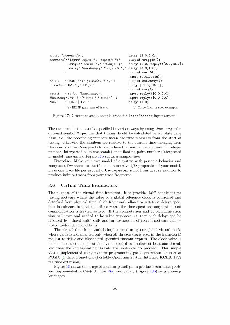
trace : (command)∗ ;command : "input" expect ("," expect)∗ ";"
| "output" action ("," action)∗ ";"
| "delay" timestamp ("," expect)∗ ";"
;
action : ChanID "(" ( valuelist )? ")" ;valuelist : INT ("," INT)∗ ;
expect : action (timestamp)? ;timestamp: ("@")? "[" time "," time "]" ;time : FLOAT | INT ;
(a) EBNF grammar of trace.
delay [2.0,3.0];
output trigger();
delay 11.0, reply()[0.0,10.0];
delay [0.0,1.0];
output send(4);
input receive(16);
output one2many();
delay [11.0, 15.0];
output many();
input reply()[0.0,0.0];
input reply()[0.0,0.0];
delay 10.0;
(b) Trace from tracer example.
Figure 17: Grammar and a sample trace for TraceAdapter input stream.
The moments in time can be specified in various ways by using timestamp rule:optional symbol @ specifies that timing should be calculated on absolute timebasis, i.e. the proceeding numbers mean the time moments from the start oftesting, otherwise the numbers are relative to the current time moment, thenthe interval of two time points follow, where the time can be expressed in integernumber (interpreted as microseconds) or in floating point number (interpretedin model time units). Figure 17b shows a sample trace.
Exercise. Make your own model of a system with periodic behavior andcompose a few traces to “test” some interactive I/O properties of your model,make one trace file per property. Use repeater script from tracer example toproduce infinite traces from your trace fragments.
3.6 Virtual Time Framework
The purpose of the virtual time framework is to provide “lab” conditions fortesting software where the value of a global reference clock is controlled anddetached from physical time. Such framework allows to test time delays spec-ified in software in ideal conditions where the time spent on computation andcommunication is treated as zero. If the computation and or communicationtime is known and needed to be taken into account, then such delays can bereplaced by “timed-wait” calls and an abstraction of control software can betested under ideal conditions.
The virtual time framework is implemented using one global virtual clock,whose value is incremented only when all threads (registered in the framework)request to delay and block until specified timeout expires. The clock value isincremented to the smallest time value needed to unblock at least one thread,and then the corresponding threads are unblocked to proceed. This simpleidea is implemented using monitor programming paradigm within a subset ofPOSIX [4] thread functions (Portable Operating System Interface 1003.1b-1993realtime extension).
Figure 18 shows the usage of monitor paradigm in producer-consumer prob-lem implemented in C++ (Figure 18a) and Java 5 (Figure 18b) programminglanguages.
28

#include <pthread.h>#include <deque>class MyMonitor {
pthread mutex t lock;pthread cond t cond;std :: deque<int> buffer;MyMonitor():
lock(PTHREAD MUTEX INITIALIZER),cond(PTHREAD COND INITIALIZER) {}
void put(int value) { // producepthread mutex lock(&lock);buffer .push back(value);pthread cond broadcast(&cond);pthread mutex unlock(&lock);
}int get() { // consume
int value;pthread mutex lock(&lock);while (buffer.empty())
pthread cond wait(&cond, &lock);value = buffer. front ();buffer .pop front();pthread mutex unlock(&lock);return value;
}}
(a) Sample monitor in C/C++.
import java.util.Vector;class MyMonitor {
Vector<Integer> buffer;MyMonitor() {
buffer = new Vector<Integer>();}/∗ produce items with put(item) ∗/synchronized void put(int value) {
buffer .add(new Integer(value));notifyAll ();
}/∗ consume items with get() ∗/synchronized int get()
throws InterruptedException{
while (buffer.isEmpty())wait();
return buffer.remove(0).intValue();}
}
(b) Sample monitor in Java.
Figure 18: Sample monitor implementations for producer-consumer problem.
A few common thread-programming rules to avoid trouble:
• Unlocking order should be in reverse order of locking, i.e. lock acquisitionand release should be nested like scopes to prevent circular dependenciesand hence deadlocks.
• Condition signalling/broadcasting should be protected by an associatedmutex lock, otherwise signals may be lost.
• A single mutex can be associated with many conditions, but each conditionshould be associated with only one mutex, i.e. the condition should beprotected by the same mutex lock in all cases when it is used.
Exercise. Make a mutant of your IUT where one of the above rules doesnot hold and run Tron test against it. (Do not change the adapter code as itmight kill Tron as well.)
The following sections explain how to adopt the implementation for virtualtime framework.
3.6.1 Dynamic Library IUT
Tron binary itself exports a set of functions necessary to implement POSIX-likemonitor. Figure 19 shows the list of POSIX functions to be replaced by Tron
implementations in order to work with virtual clock, please lookup the POSIXprogrammer’s manual (included in most Linux distributions) of these functionsfor detailed descriptions.
Figure 20 shows the list of symbols Tron is exporting. The symbols re-fer to corresponding POSIX function implementations and more. Almost all
29

1 int pthread create(pthread t∗, pthread attr t∗, void∗ (∗start)(void∗), void∗);2 int pthread join(pthread t, void∗∗);3 int pthread mutex init(pthread mutex t∗, const pthread mutexattr t∗);4 int pthread mutex destroy(pthread mutex t∗);5 int pthread mutex lock(pthread mutex t∗);6 int pthread mutex unlock(pthread mutex t∗);7 int pthread cond init(pthread cond t∗, const pthread condattr t∗);8 int pthread cond destroy(pthread cond t∗);9 int pthread cond wait(pthread cond t∗, pthread mutex t∗);
10 int pthread cond timedwait(pthread cond t∗, pthread mutex t∗, const struct timespec∗);11 int pthread cond signal(pthread cond t∗);12 int pthread cond broadcast(pthread cond t∗);13 int gettimeofday(struct timeval ∗tv, struct timezone ∗tz);
Figure 19: POSIX thread functions.
1 int (∗tron thread create) (pthread t∗, const pthread attr t∗, void∗ (∗start)(void∗), void∗);2 int (∗tron thread join) (pthread t, void∗∗);3 int (∗tron mutex init) (pthread mutex t∗, const pthread mutexattr t∗);4 int (∗tron mutex destroy) (pthread mutex t∗);5 int (∗tron mutex lock) (pthread mutex t∗);6 int (∗tron mutex unlock) (pthread mutex t∗);7 int (∗tron cond init )(pthread cond t∗, const pthread condattr t∗);8 int (∗tron cond destroy)(pthread cond t∗);9 int (∗tron cond wait) (pthread cond t∗, pthread mutex t∗);
10 int (∗tron cond timedwait) (pthread cond t∗, pthread mutex t∗, const struct timespec∗);11 void (∗tron cond signal) (pthread cond t∗);12 void (∗tron cond broadcast) (pthread cond t∗);13 void (∗tron gettime) (struct timespec∗);14
15 typedef enum TKMode t { TKHostClock, TKLogClock, TKExtClock };16 TKMode t TKMode; // read−only variable for time keeping mode17 int setHostClock();18 int setLogicalClock(bool reg=true);19 int setLogicalClockService(bool reg=true, int port=0x1979);20 int setSocketClock(const char∗ host, int port=0x1979, bool reg=true);
Figure 20: Tron functions to replace a subset of POSIX.
function signatures are the same as their POSIX analogs, the only exceptionsare condition signalling (functions always succeed) and getting value of clock(gettimeofday operates on timeval structure rather than timespec which ismore convenient when working with timedwait). The symbols are of function-pointer type in order to be able to turn on or off the virtual time frameworkwithout recompiling. The value of variable TKMode can be used to determinedwhat time-keeping mode is used (usually it is not necessary): TKHostClock
means the host clock, i.e. the underlying OS POSIX layer is called directly,TKLogClock means the local logical (virtual) clock, TKExtClock means the re-mote logical clock. The functions at lines 16-18 can be used to set a particulartime framework (also not necessary as it is done by -Q command line option).The local logical clock also creates a local TCP/IP server socket and listensfor remote connections (see Section 3.6.2), so only one instance of local logicalclock should be used, the other processes should use the remote clock accessedvia TCP/IP sockets (e.g. Section 3.6.3). The parameter reg controls whetherthe calling thread should also be added to the pool of virtual threads, this isusually needed only for the main process thread as all other threads (createdvia tron thread create) are automatically added once the main thread sets-upthe required framework.
30

The implementation of tron functions are linked inside Tron binary file.The trick is that dynamic loader looks-up and resolve the tron symbols auto-matically also for any dynamic library loaded as adapter. Currently this worksvery well on Linux (see the button example) but not on Windows (suggestionsfor possible solutions are welcome).
Exercise. Convert the code in Figure 18a to use virtual time framework.
3.6.2 Remote Virtual Clock Service
POSIX threads are good for synchronizing threads within the same processaddress space, however it does not help to communicate with remote IUTs. Analternative could be to use Remote Procedure Calls (RPCs) or some CommonObject Request Broker Architecture (CORBA) library, however such solutionsrequire special permissions or tend to be big libraries while virtual clock issimple and does not need complicated data passing. In this section we describehow to access the virtual clock in Tron process via TCP/IP sockets which islightweight, mature and pervasive throughout operating systems today.
Virtual clock framework is turned on by -Q option (Section 4.1): Tron caneither create its own clock server when -Q has a port number as argument or“log” (implies default port number 6521) or use external virtual clock with amachine address and a port number (e.g. connect to another instance of Tron).
Virtual clock is always associated with socket server and threads are as-sociated with client sockets. The protocol is designed so that each thread isidentified by a separate socket connection: one duplex connection per thread.All thread operations are carried out in the context of that connection. More-over, all socket communications are synchronous for client thread, meaning thatit is trivial to use and there is no need for complicated locking mechanisms toprotect socket connection from multi-threading nor creating special data struc-tures. It is important that client threads do not share their connections withother threads as such sharing is meaningless and asks for trouble.
Virtual clock protocol consists of a set of commands corresponding to POSIXlayer. The commands are carried out synchronously: client sends a virtual clockcommand with its arguments and waits for a response containing the result ofoperations. Server may respond with a delay if the command was timed-waitrelated, thus effectively putting the client thread into blocked state until therequired (virtual) time delay elapses.
The protocol starts with client thread establishing connection to a clockserver and sending its name (a human friendly identifier, useful for debugging)in ASCII N-string format (first byte denotes the length of a string, then up to255 bytes of the string itself). The new connections automatically register a newthread in virtual time framework. After the name is sent (thread registered),the client thread may start using virtual clock by sending commands.
The following is a list of commands used in virtual time protocol:
Mutex initialize. Initializes new mutex variable.Bytes: 0 1 2 3 4
Request: 3Response: mutex ID
Mutex destroy. Deletes mutex with specified ID. Response is empty, i.e. thereis no result to wait for.
31

Bytes: 0 1 2 3 4Request: 4 mutex ID
Response:
Mutex lock. Locks a mutex with the specified ID. Response contains Tron
code from Table 2.Bytes: 0 1 2 3 4
Request: 5 mutex IDResponse: code
Mutex unlock. Unlocks a mutex with the specified ID. Response containsTron code from Table 2.
Bytes: 0 1 2 3 4Request: 6 mutex ID
Response: code
Condition initialize. Initializes new condition variable.Bytes: 0 1 2 3 4
Request: 7Response: condition ID
Condition destroy. Deletes a condition with the specified ID. Response isempty, i.e. there is no result to wait for.
Bytes: 0 1 2 3 4Request: 8 condition ID
Response:
Conditional wait. Release the specified mutex, wait until the specified con-dition is triggered, re-acquire the mutex and return an operation code.Response contains Tron code from Table 2.
Bytes: 0 1 2 3 4 5 6 7 8Request: 9 condition ID mutex ID
Response: code
Conditional timed wait. Release the specified mutex, wait until the specifiedcondition is triggered or time has elapsed, re-acquire the mutex and re-turn an operation code. Time is specified as absolute signed 32-bit integervalues from beginning of era (see Get time command below). Responsecontains Tron code from Table 2.
Bytes: 0 1 2 3 4 5 6 7 8 9 10 11 12 13 14 15 16Request: 11 condition ID mutex ID seconds microseconds
Response: code
Conditional delay. Release the specified mutex, wait until the specified con-dition is triggered or time has elapsed, re-acquire the mutex and return anoperation code. Time is specified as relative signed 32-bit integer valuesfrom current time (see Get time command below). Response containsTron code from Table 2. The command is provided as a shorthand for acommon combination of Get time and Conditional timed wait.
Bytes: 0 1 2 3 4 5 6 7 8 9 10 11 12 13 14 15 16Request: 11 condition ID mutex ID seconds microseconds
Response: code
Condition signal. Notifies one of the threads waiting on the specified condi-tion. There is no response to wait for.
32

Bytes: 0 1 2 3 4Request: 12 condition ID
Response:
Condition broadcast. Notifies all of the threads waiting on the specified con-dition. There is no response to wait for.
Bytes: 0 1 2 3 4Request: 13 condition ID
Response:
Get time. Returns the absolute time-stamp of current time since era in two32-bit integer numbers. Era, or the value of 0 in virtual time denotes themoment the virtual clock was created.
Bytes: 0 1 2 3 4 5 6 7 8Request: 14
Response: seconds microseconds
Thread quit. Removes the registration of the thread and releases the associ-ated resources so that other threads may continue using the virtual clockwithout this one. The deactivated threads should activate before termi-nation (see Activate thread). There is no response to wait for.
Bytes: 0 1 2 3 4Request: 127
Response:
Thread deactivate. Temporarily (until activation) removes the current threadfrom virtual time accounting. This is normally used only by specialadapter threads (e.g. SocketAdapter) which wait for incoming actionsfrom elsewhere (e.g. socket connection) rather than for regular conditionvariable notifications. The deactivated threads do not participate in timeaccounting but they are still important in notifying other threads aboutincoming actions. All other threads should not use deactivation mecha-nism at all.
Bytes: 0 1 2 3 4Request: 1
Response: code
Thread activate. Activates the deactivated thread (see Thread deactivate).Should be used only by special adapter threads (like one in SocketAdapter)just before termination.
Bytes: 0 1 2 3 4Request: 2
Response: code
Table 2 describes possible 32-bit number codes returned by Tron specificto virtual time framework via TCP/IP. The names are taken from POSIX Cidentifiers whose actual values may be different on various operating systems,thus the native error codes are translated to unique values in this table.
All the integers are converted to network byte order (see htonl(3) C functionmanual).
Some languages (like C and Java) provide a lot of options for configuringsocket connections, hence consider disabling Nagle algorithm to send data assoon as possible and always do an explicit flush operation to make sure that the
33

Table 2: Tron error codes for virtual time via TCP/IP sockets.
Name Code Description
OK 0 No error, operation succeeded or condition has been triggered.ERROR 64 Unexpected error: uncommon failure that is not handled by this
error code translation.ETIMEDOUT 65 Specified time has elapsed.EINTR 66 Interrupted system call.EBUSY 67 Device or resource is busy.EINVAL 68 Invalid argument: invalid values or different mutexes supplied
for concurrent operations on the same condition variable.
command and its arguments are dispatched. Other languages (like Python) relyon constructing TCP packets explicitly. Tron implements data buffering andtreats the incoming flow of commands as a stream rather than packets, thus itis able to deal with both types of network APIs.
3.6.3 Virtual Clock for Java
Tron distribution contains sample Java implementation of virtual clock proto-col via TCP/IP sockets that can be enabled in combination with SocketAdapter
implementation in Java.Virtual time framework in Java uses VirtualThread which extends Thread
class and takes care of establishing connection to virtual clock. Thread synchro-nization is implemented through VirtualLock and VirtualCondition classeswhich implement interfaces from java.util.concurrent .locks package (avail-able in Sun JDK since Java 5). The synchronization methods identify the call-ing VirtualThread objects and use their methods to carry out virtual timecommands, thus in effect these methods use the context (socket connection) ofparticular thread to carry out operations on virtual clock without sharing ormixing with other threads. Eventually all synchronizations are resolved insidevirtual clock server process.
Unfortunately the synchronized keyword is not supported directly and hasto be changed to equivalent code using interfaces in java.util.concurrent
.locks package.The following is a list of actions needed to adopt virtual time framework for
any Java application:
• All Java threads should extend VirtualThread class instead of java.lang.Thread. Note that this isolates the application from events in (graphical)user interface.
• Monitor methods should be modified as follows:
– Synchronized methods and sections should be replaced by blocks sur-rounded by VirtualLock.lock and VirtualLock.unlock().
– java.lang.Object.wait() should be replaced with VirtualCondition
.await() surrounded with appropriate VirtualLock object lock()and unlock() methods.
34

– java.lang.Object.notify() and java.lang.Object.notifyAll()
replace with VirtualCondition.signal and VirtualCondition .signalAll()
respectively.
• Before any thread creation, set the remote virtual clock via VirtualThread.setRemoteClock(String, int) method call (once is enough).
Exercise. Convert the code in Figure 18b to use virtual time framework.
4 Testing
This section describes the features of test execution process of Tron. We startby describing the command line options, proceed with how to read and interprettest logs and explain the test verdict and diagnostics information.
4.1 Command Line Options
The following is a list command line options that developer can use to controlthe behavior of Tron. Each item starts with the key controlling the feature,followed by the description of feature. Some options affect the Uppaal enginedirectly (marked with a star ∗) while others are completely Tron specific.
-A∗ Use convex-hull approximation.
-B path provide a file path to store benchmark log (default /dev/null), seeSection 4.2.
-D path specify a file path to store driver log (default /dev/null), see Sec-tion 4.2.
-F future specifies how far into the future (in model time units) Tron shouldpre-compute the internal transition closure of a state-set estimate in orderto make reasonable test choices. The setting limits the delay in symbolic-future operations in order to prevent Tron from exploring too far ofinternal and non-interactive (without observable input/output events) be-havior. Default is 0, which means that Tron will take immediately en-abled transitions and will not take any internal time-guarded transitions(without choosing to delay and satisfy their guards first). Larger valuesare recommended to reach more choices, and smaller values are preferredto reduce the performance penalty required for future pre-computations.For periodic systems good heuristic candidates are: the duration of thelongest period or least common multiple of all periods. The feature can bedisabled by setting -1: then internal transition closure computation willbe turned off and not a single internal transitions will be considered whencomputing available input choices; this might be reasonable only if thereare very few internal transition edges or the input/output events are veryfar apart in time (e.g. further than -P setting) and hence disabling is notrecommended in general.
-H n∗ sets the hash table size for bit state hashing to 2n (default 27). Thesetting influences the three passed-waiting lists (state-sets) in Tron. Thedefault value come from reachability algorithm where the hash-table has
35

to store entire system state space. During testing however, the state-setsare typically much smaller and n can be safely around 10 (1024 entries)to save some memory.
-I name specifies the implementation, or rather the location of the adapterto implementation where name is a file path to a dynamically linked li-brary with adapter to an implementation, or one of the following built-inadapters:
TraceAdapter standard input/output stream adapter, see Section 3.5;
SocketAdapter remote TCP/IP socket adapter, see Section 3.3.
-P delay specifies the delay choice strategy (see also Section 4.4). The delay
can be one of the following:
eager : delay as little as possible before firing a chosen action-transition.The choice is typically bound by the guards on edges (and invariantson the target location vector), Tron will choose the minimum or 0if no guard is on the chosen edge.
lazy : delay as much as possible before firing a chosen action-transition.The choice is typically bound by invariants on current (and target)location vector, Tron will choose the maximum allowed or infinity(actually until the testing timeout) if no invariant is specified.
random : delay randomly within the bounds specified by the environmentmodel (default). The choice is typically bound by the guards ona chosen edge and invariants on current (and target) environmentlocation vector, hence the choice is randomly resolved to fit into thisinterval.
short,long : try random delay bounded by one of positive integer num-bers: (short and long). The numbers specify the longest delaychoice allowed in model time units, the interpretation “short” and“long” is arbitrary and not enforced, but rather a hint that periodicsystems often have two or more periods of very different granularity.The concrete delay choice is still random and based on the specifica-tion (bounds will be ignored if specification require longer delays) butchoices are guaranteed to be shorter or equal to max(short, long).This is useful to limit delays if there are states without invariantsand developer wants more interactive (with more observable actions)test runs.
Notice that the delay strategy is orthogonal to -P option: -F controls howmany action transitions are available (reachable) to choose from, while -P
chooses the delay based on the information on chosen action transition.
-Q log sets logical (simulated or virtual) time clock instead of the default realhost’s clock (and does not start clock service).
-Q port -Q host:port Parameter port specifies that virtual clock service shouldbe started on port number port or all clock requests forwarded to remotevirtual clock service on machine called host and port number port. SeeSection 3.6 for details about Tron’s virtual clock services.
36

-S filename Append the verdict, I/O and duration to file (default /dev/null),see Section 4.2.
-U∗ Unpack reduced constraint systems before relation test.
-V prints version information and exits.
-X integer initializes random number generator by a given integer value (de-fault value is read from the host’s system clock).
-h prints a short version of this option list description and exits.
-i <dot|gui> prints a signal flow diagram of the system and exits. There aretwo output formats available:
dot : dot [3] graph, expects formated standard input (see Section 2.2):"input" (channel)∗ "output"(channel)∗
gui : non-partitioned flow information for Tron GUI;
-o filename Redirect output to file instead of stdout, see also -v and Sec-tion 4.2.
-s <0|1|2>∗ selects the exploration order of reachability algorithm. This shouldnot have a significant impact on Tron performance, unless -F value islarge and there are many internal transitions in the model. There are thefollowing options:
0 : Breadth first (default)
1 : Depth first
2 : Random depth first
-u inpDelay,inpRes,outDelay,outRes
-u inpRes,outRes Observation uncertainty intervals in microseconds:
inpDelay : the least delay that takes to deliver input,
inpRes : possible additional delay for delivering input,
outDelay : the least delay that takes to observe output,
outRes : possible additional delay for observing output.
-l latency Specifies the maximum input scheduling latency in microsecondswhen offering the input. The value will be subtracted from the upperbound of the input timing which should prevent missing the input dead-lines (verdicts like “input executed too late” and driver warnings like“DRIVER: 1193663117.714029s has passed, now it’s 1193663117.714033s”).This option is similar to input observation uncertainty except that it doesnot affect the time-stamping after the input has been executed.
-v <0+1+2+4+8+16> sets verbosity of a test log printed to standard outputstream (or file specified by -o option). The verbosity specifies what infor-mation should be included in the test log, see Section 4.2 for log descrip-tion. The values of interest should be added to produce final verbositynumber:
37

= 0 : only verdict, disable engine event output (default),
& 1 : progress indicator for interactive experiments,
& 2 : test events applied in the Uppaal engine,
& 4 : available input and delay choices for emulation,
& 8 : backup state set and prepare for final diagnostics,
&16 : dumps current state set on each state set update.
If partitioning option -i is used instead of test run then partitioning mes-sages can be controlled by the following verbosity values:
0 : none,
1 : errors,
2 : errors and warnings (default),
3 : errors, warnings and diagnostics.
-w integer specify additional number of model time units in attempt to test(violate) invariants. Useful under assumption that invariants are not usedin the model of environment. This option is obsolete starting from ver-sion 1.4b1, where IUT invariants are removed from environment emulation(hence invariants tested under given environment) if system model parti-tioning is properly done (no partitioning errors are detected).
-q be quiet and do not display the copyright message.
Uppaal engine also reacts to the following OS environment variables:
UPPAAL DISABLE SWEEPLINE : disable sweepline method,
UPPAAL DISABLE OPTIMISER : disable peephole optimiser,
UPPAAL OLD SYNTAX : use version 3.4 syntax for parsing old system models.
The value of these environment variables do not matter, defining them is enoughto activate the features in question.
4.2 Logging
There are four ways to log test runs:
Engine log contains information about operations performed in Uppaal en-gine. Messages follow the Tron online test algorithm. The engine eventsare sent to standard output by default, and can be redirected to a file via-o option. The verbosity of messages can be adjusted by -v option. Thepurpose is to display the current status of an online test run.
Driver log contains test interface description and time-stamped informationabout input and output events. The log file is specified by -D option andfollows the TraceAdapter format (see Figures 16 and 17a). The purpose isto log input and output events precisely and to enable the trace replay withTraceAdapter in monitoring mode, potentially with different options.
38

Statistics log contains one line summary per one test run. Log file is speci-fied by -S option. The purpose is to record many test runs in one file toprovide statistical measures on how many inputs and outputs have beenperformed, how many test runs passed and failed. The statistics log con-tain the following columns:
1. The initial random seed of a test run. By default it is UNIX times-tamp in seconds since the Epoch, see -X option in Section 4.1.
2. The test verdict of a test run in one word.
3. The number of inputs sent to an IUT.
4. The number of outputs received from an IUT.
5. The duration of a test run in model time units.
Here is an example of a statistics log:
1160727325 PASSED 13195 23753 100000
1163934755 FAILED 2 13 38
1163934756 INCONC 2 13 18
Benchmark log contains a one line timing measurement per one Uppaal en-gine operation (after delay or after action updates) for benchmarkpurposes. The log file is specified by -B option. The purpose is to helptuning the Uppaal engine for testing purposes. The file consists of fourcolumns:
1. Zero or one: “0” stands for after delay and “1” stands for after
action operations.
2. The state set size before the operation.
3. The state set size after the operation.
4. The high resolution (OS specific) time estimate of operation durationin nano-seconds.
4.3 Time Stamping
One of the key activities in test run evaluation is time-stamping the real I/Oevents and mapping those real time stamps into model time and back. Onlinetesting has an additional challenge for testing tool: how to incorporate timedelays spent by the testing tool itself and provide objective verdict if test fails(e.g. the testing tool may delay too long due to expensive computations andthus fail to fulfill the assumptions of environment model). Tron offers over-approximating method to match real time values into model time. In orderto explain the idea behind this method we go through input offering scenariosincrementally: in virtual time framework, in naive real time and real time withobservation uncertainties. At the end of this section we explain the details ofmapping real time instances into model time instances and back together withobservation uncertainties.
39

4.3.1 Virtual Time
Consider the following input offering scenario shown in message sequence chart(MSC) in Figure 21:
1. Tron asks what time is now and saves the value into variable t.
2. Tron converts the real time interval [t, t+F ] to model time interval [L,U ],where F is the future horizon constant from -F option.
3. Tron asks Uppaal to update state set with delay and τ -transitions forall delays between L and U model time stamps. The result is saved intovariable S.
4. Tron asks Uppaal about what input and output events are availablefrom a given state set S. The set of inputs is saved into variable inps.
5. Tron chooses some input action i randomly from the set of input actions.The input action is enabled at model time interval [Li, Ui].
6. Tron computes the real time interval [li, ui] corresponding to the modeltime interval [Li, Ui].
7. Tron chooses a specific target time instance ttgt from real time interval[li, ui]. By default, Tron chooses a random instance, or applies the delaychoice strategy specified by -P option otherwise.
8. Tron asks driver to delay until the ttgt time instance. Notice that so farthere were no delay requests since the first getTimeNow call, hence therewas virtually no delay (zero virtual time) until this step and the only delayin this scenario happens in this step.
9. After delay, Tron observes that there were no outputs and immediatelyasks driver to offer an input i.
10. Driver does not make any delays and passes the input i to adapter andstamps this input as executed at te real time instance. Note that te isequal to ttgt as there was no virtual time delay since ttgt instance wasreached.
11. Tron maps the real time stamp te of the input action into model interval[Le, Ue] (this is potentially much narrower interval than [Li, Ui]).
12. Tron asks Uppaal to update (affectively filter and constrain) the stateset to describe system states within model time interval [L,U ].
13. Tron asks Uppaal to compute a new state set after action i.
Output time-stamping is much simpler: driver can be interrupted at anytime by incoming output and thus time-stamp immediately. The output eventwith its time-stamp is discovered by Tron during the “wait” requests, the realtime-stamp is converted to model time-stamp and applied to state set in thesame way as input events.
40

Uppaal
engine
Tron
tester
Reporter
driver
getTimeNow
0
t
[L, U ] = R2M(t, t + F )
τ([L, U ])
updated S
inputs(S)
(inps)
i[Li, Ui] = random(inps)
[li, ui] = M2R(Li, Ui)
ttgt = choose(li, ui)
wait until ttgtC, ttgt
ttgt − t no output
0
offer i
(i)
i[te, te]
[Le, Ue] = R2M(te, te)
τ([Le, Ue])
updated S
after(S, i)
updated S
msc Input time-stamping in controlled (virtual) time case.
Figure 21: Scenario for offering an input to IUT and relevant timestamps invirtual time case.
4.3.2 Naive Real Time
From Figure 21 it is evident that in virtual time framework the time spentfor computing, choosing and delivering the input is being ignored, and onlyexplicit delays are counted. This assumption does not hold in real time andthus algorithm has to be adjusted to accommodate such delays. Figure 22shows input offering scenario adjusted for real time, which differs from virtualtime in the following ways:
1. The performance of input action calculation is unpredictable as it dependson the complexity of a system model and on particular state set, hencethis delay is reflected in choosing the timing for the input: the intervalis constrained from below by an extra time-stamp tc. This reduces thedriver warnings that the ttgt instance of time is already in the past at the
41

time of “wait until” request. We still rely that the window for input isbig enough to incorporate the chosen input: tc < ui, and hence any driverwarning about ttgt being in the past is a sign that Tron does not keepup with the requirements (boundary Ui) from the environment model.If tc happen to be after ui already before offering this input, then theinput is discarded and another input is chosen instead (the whole inputcomputation is restarted).
2. The time-stamping of the input execution is performed by two time stamps:between ttry and tdone, i.e. just before sending input and just after the
send. The acquired model time interval [Le, Ue] denotes that the inputhappened somewhere in between, hence all possibilities has to be incorpo-rated into the state set.
4.3.3 Internal Latency
So far, we still rely on the fact that Tron is woken up at precisely ttgt momentand further input deliver happen instantaneously. This is not always true andcannot be predicted in all operating systems due to latency (jitter) in processscheduling and communication, however it is still important to be able to offerthe input without violating ui boundary. In this section we show how Tron
adjusts input offering with a latency parameter -l L that specifies the worstlatency duration. The latency is incorporated into M2R function mappingwhich subtracts this amount of real-time from original ui value, thus discardingthe inputs which are too late with respect to upper boundary and local latencytaken into account.
4.3.4 External Latency
Often test adapter introduces significant delays (communication latency) andI/O buffering. The only fair way to test such systems is to model test adapter aspart of IUT. One way of adapter modeling is to provide explicit model in systemspecification (e.g. add timed automata processes for adapter). Typical adapterreceives a signal, puts it into buffer, delays the signal (“signal is traveling”) andretransmits the signal for destination process. In this section we show how toacquire I/O timing characteristics of such adapter.
Figure 23 shows how IUT and tester use digital clocks to timestamp I/Oevents. For simplicity we assume perfect digital clock, which updates the timevalue with a period of it’s resolution, and time (value) is synchronized globally.We assume that adapter causes a delay D1 for output and D2 for input. Wealso assume that timestamping code runs instantly without delay, otherwise thisdeterministic delay can be added to adapter delay. At IUT side I/O happensat t1 and t10 instances, however due to its digital clock time sampling IUT maythink it happens at t2 and t11. Similarly at tester side I/O happens at t3 andt7, while tester timestamps these events at t4 and [t6, t9]. Then observe thefollowing inequalities:
t3 − D1 = t1 = t3 − D1
t2 − siut ≤ t1 < t2 + R1
t4 ≤ t3 < t4 + R2
⇒
{
t4 − D1 ≤ t1 < t4 − (D1 − R2)t4 − (D1 + R1) < t2 < t4 − (D1 − R2)
(2)
42

Uppaal
engine
Tron
tester
Reporter
driver
Adapter
media
getTimeNow
t = Ct
[L, U ] = R2M(t, t + F )
τ([L, U ])
updated S
inputs(S)
(inps)
i[Li, Ui] = random(inps)
[li, ui] = M2R(Li, Ui)
getTimeNow
tc
ttgt = choose(max(li, tc), ui)
wait until ttgt
C, ttgt
treq = C
ttgt = C
no output
offer i
(i)
ttry = C
idone
tdone = C
i[ttry, tdone]
[Le, Ue] = R2M(ttry, tdone)
τ([Le, Ue])
updated S
after(S, i)
updated S
msc Offering input in real-time without observation uncertainties.
Figure 22: Scenario for offering an input to IUT and relevant timestamps inreal time case without observation uncertainties.
t7 + D2 =t10= t7 + D2
t10 − R1 <t11≤ t10t6 ≤ t5 ≤ t7 ≤ t8 < t9 + R2
⇒
{
t6 + D2 ≤t10< t9 + D2 + R2
t6 + D2 − R1 <t11< t9 + D2 + R2
(3)
43

�������������� ��������D1−R2
T
D2
output
D2−R1D2
D2+R2D1+R2D1
IUT
Adapter
Clock
Tester
Model
Clock
R2
outputt1
t4
t3t8
t7t5
input
input
t9t6
R1t10
t2 t11
Figure 23: I/O delays in the adapter: IUT sends output at t1 while its clockwith resolution R1 is showing t2, the output is delayed by adapter by durationD1 and sensed by tester at t3 while testers clock with resolution R2 is showingt4; before sending input tester looks up its clock at t5, observes value t6, sendsinput at t7, looks up the clock again at t8 and observes value t9, then inputarrives at IUT at t10 while IUT’s clock is showing t11; the real time values arethen mapped onto model time scale with resolution of T (real time value of onemodel time unit).
Therefore tester may conclude that at IUT side output happens at(
t4 − (D1 +
R1), t4−(D1−R2))
and input happens at(
t6+D2−R1, t9+D2+R2
)
. Therefore
adapter has a minimum δinpmin = D2−R1 and a maximum δinp
max = D2+R2 delaysfor input, and a minimum delay δout
min = D1−R2 and a maximum δoutmax = D1+R1
for delays output. These delays are marked in Figure 23.In the following we show how to incorporate real world imperfections:
• If clocks are not perfect and have some kind of jitter (latency distribution),then the clock resolution values R1 and R2 can be described by the largestpossible time steps.
• If adapter has a non deterministic delay then the values of D1 and D2 canbe described by shortest and longest adapter delays.
Therefore, if R1, R2,D1,D2 are distributions rather than constant values, then:
δinpmin = min(D2) − max(R1) (4)
δinpmax = max(D2) + max(R2) (5)
δoutmin = min(D1) − max(R2) (6)
δoutmax = max(D1) + max(R1) (7)
These external latency boundaries can be built into the IUT requirementsmodel or provided to Tron by -o δ
inpmin, δinp
max − δinpmin, δout
min, δoutmax − δout
min option.Further details and assumptions for the latter option are in the following sec-tions.
44

4.3.5 Observation Uncertainties
A straightforward adapter modelling way is to provide one process per one signaland have as many processes as there can be signals at one time, then reusethese processes to handle infinitely many signals. Such model is quite generic(fits many systems) but contains high degree of non-determinism (varying signalspeed) and parallelism (even if signal ordering is deterministic) which lead tolarge state sets just to be able to handle many simultaneous I/O events. Manyevents at the same time is more of an exception than a rule and thus such blindmodeling is may have poor average performance and greatly obfuscates testdiagnostics.
Tron provides an alternative way of modeling adapter latencies via obser-vation uncertainties: Tron does not know when the input signal reaches IUT,only the moment of input dispatch is timestamped locally; the same applies tooutputs, Tron does not know when IUT has sent an output signal, only thearrival of output signal is timestamped. Knowing basic communication jittercharacteristics allows Tron to compute a precise estimate of when I/O actuallyhappened. We assume that communication of input signal takes at least δ
inpmin
and at most δinpmax of real time and output signal takes at least δout
min and atmost δout
out of real time. Then the local I/O timestamps can be adjusted by theseparameters to calculate the remote timestamps and get the estimate when I/Ohas been sent/received from IUT perspective, thus affectively abstracting awaythe whole adapter layer and its complexity. Figure 24 shows how I/O timinguncertainties are incorporated into input offering scenario. This still has animportant assumption and price to pay:
• The adapter communication delay has to fit onto environment and IUTmodel synchronization time:
– IUT model is assumed to be input enabled, thus there are no addi-tional assumptions for IUT requirements model.
– Environment may have constraints for inputs: lower bound li is notdirectly affected as input estimate can only be delayed, but upperbound ui can be violated, thus we assume that this boundary is ableto consume adapter latency: tdone + δinp
max < ui – this can be checkedduring test run and environment model adjusted. Then, the latestmoment for input scheduling is ui−δinp
max−L and obviously it cannotbe earlier than li, hence we assume that environment model satisfiesui − δinp
max −L < li for all inputs – this too can be checked during testrun and the environment model adjusted to fit this assumption.
– IUT model may have constraints over outputs and thus not entireinterval of output timestamps may be applicable and thus some partsof interval may be discarded. Note that we compute an interval ofall possible output timestamps, including the actual output timing,thus at least one point in that interval is required for IUT to pass thistest step and it is safe to assume that others did not actually happen.If output did happen at the time the IUT constraints did not allowbut it was included in the interval timestamp, then IUT actuallyfailed this test step, but Tron have no possibility of detecting suchpossibility, thus further testing is based on some false assumptions
45

Uppaal
engine
Tron
tester
Reporter
driver
Adapter
media IUT
getTimeNow
t
[L, U ] = R2M(t + δinmin, t + F )
τ([L, U ])
updated S
inputs(S)
(inps)
i[Li, Ui] = random(inps)
(li, ui) = M2R(Li, Ui)
getTimeNow
tc
ttgt = rand(max(li, tc), ui)
wait until ttgt
C, ttgt
ttgt = C
no output
offer i
(i)
ttry = C
iδin
min
iδin
max
done
tdone = C
i[ttry, tdone]
(Le, Ue) = R2M(ttry, tdone)
τ([Le, Ue])
updated S
after(S, i)
updated S
msc Real-time with latency and observation uncertainties.
Figure 24: Scenario for offering an input to IUT and relevant timestamps inreal time case with observation uncertainties, assuming F ≥ δinp
max.
which hopefully will come out as failure at some later step, and if itdoes not, then it is safe to conclude that such failure is not observablydetectable (under our testing assumptions) and thus we should notcare.
46

– Environment model is assumed to be enabled for all possible outputsat any time, thus there are no additional assumptions for outputs inenvironment model. If the environment model is not enabled thenthere will be false assumptions about output timestamp and thereforewe cannot allow it.
For example, the offered input should be possible at all instances betweenttry + δ
inpmin and tdone + δinp
max.
• If several I/O events are timestamped by overlapping intervals then allpossible event orderings have to be considered as it is not possible todetermine which event happened first. This may have some performancepenalties but only when multiple events clash within an adapter (not com-mon) thus preserving good average performance.
4.3.6 Model Time and Real Time
T is a real time value (in microseconds) of one model time unit; L is inputscheduling latency; δ
inpmin, δinp
max, δoutmin and δout
max are observation uncertainty pa-rameters describing adapter I/O latency distribution (jitter). Bound strictnessnotation:
x satisfies strict lower bound L ⇔ L < x
x satisfies non-strict lower bound L ⇔ L ≤ x
x satisfies strict upper bound U ⇔ x < U
x satisfies non-strict upper bound U ⇔ x ≤ U
From Figure 23 we can derive the following formulas to convert model timeunits to real time and back:
R2M real time to model time for estimating input delivery:
Linp =
{
strict⌊ linp+δ
inp
min
T
⌋
if{ linp+δ
inp
min
T
}
> 0
non-strict⌊ linp+δ
inp
min
T
⌋
otherwise(8)
Uinp =
{
strict⌊uinp+δinp
max
T+ 1
⌋
if{uinp+δinp
max
T
}
> 0
non-strict⌊uinp+δinp
max
T
⌋
otherwise(9)
R2M real time to model time for estimating output origin:
Lout =
{
strict⌊ lout−δout
max
T
⌋
if{ lout−δout
max
T
}
> 0
non-strict⌊ lout−δout
max
T
⌋
otherwise(10)
Uout =
{
strict⌊uout−δout
min
T+ 1
⌋
if{uout−δout
min
T
}
> 0
non-strict⌊uout−δout
min
T
⌋
otherwise(11)
M2R model time to real time for input scheduling:
linp =
{
Linp · T − δinpmin + ε if Linp is strict
Linp · T − δinpmin otherwise
(12)
uinp =
{
(Uinp − 1) · T − δinpmax − L if Uinp is strict
Uinp · T − δinpmax − L otherwise
(13)
47

ε is the smallest countable value of real time unit (1µs), it is independentfrom any clock resolution. Its purpose is to avoid scheduling input at theexact lower bound.Then [linp, uinp] is a real time interval for which input can be deliveredsafely without violating constraints. If linp > uinp then environment re-quirements are too strict for such test adapter, and it is not possible toschedule such input reliably.Note that Tron subtracts almost whole last time unit from upper boundas Tron does not know the exact timing offset within one time unit, e.g.consider situation where environment requires immediate input after someoutput is observed, then safe upper bound uinp should be less or equal tolower bound linp (i.e. now, at the time of output) and not within one timeunit as symbolic zones might suggest in the middle of time unit.
Notice that latency and observation uncertainty features can be turned offby just using value 0 (default).
4.4 Input Choices
If environment model permits several different input actions, then Tron choosesa random one and the exact delay to be performed before offering the choseninput is decided by one of the following strategies specified in -P option:
Random delay is chosen by a random function from an interval of possibledelays computed by Uppaal engine. This is a default setting.
Eager delay is the shortest delay from an interval of possible delays computedby Uppaal engine.
Lazy delay is the longest delay from an interval of possible delays computedby Uppaal engine.
Bounded by s or l delay is chosen by a random function from an interval ofpossible delays constrained by either upper bound s or l. If both s andl are shorter than the shortest allowed delay, then the shortest alloweddelay is chosen. s stands for a “short delay” and l is “long delay”, and thechoice between them is resolved by a random function. The “short” and“long” semantics is not enforced but provided as a hint to developer thatthey can be used to constrain choices for “fast” (low time granularity) and“slow” (high time granularity) inputs.
5 Diagnostics
Currently TRON provides a verdict and simple conclusion based on last goodstate set. Algorithm 1 shows the pseudo-code for drawing the conclusion. Ac-tion is class containing data about actual input/output observed: channel, val-ues for associated data, the interval of estimated execution time (lowerBoundand upperBound). Choice is class containing data about possible choice forinput stimuli: channel, values for associated data, the interval of enabled time(minBound and maxBound). Choice objects are generated in Uppaal engine,while Action objects are created, decoded and time-stamped by driver.
48

Function Conclusion(StateSet backup, Action a, Choice c): verdict –based on last good state set.
Ain =EnvOuput(backup); Aout =ImpOuput(backup);1
if a then // did state set become empty upon observable I/O?2
if a.isInput then // there was choice c for this input3
print “Decided to input c but executed as a”;4
print “The target state was:” c.targetState;5
if c.maxBound < a.lowerBound then6
return Inconc(“Input executed too late. . . ”);7
else if a.upperBound < c.minBound then8
return Inconc(“Input executed too early. . . ”);9
else // a is an output10
print “Got unacceptable output a”;11
print “Expected outputs:” Aout;12
boolean tooLate=false, tooEarly=false;13
forall co ∈ Aout do // Let’s look at all possible outputs14
if a.chan==co.chan then // bug: data part is ignored15
if a.upperBound < co.minBound then16
tooEarly=true; // disjunct intervals?17
if a.lowerBound > co.maxBound then18
tooLate=true; // disjunct intervals?19
if tooLate ∧¬ tooEarly then20
return Failed(“Output produced too late”);21
else if ¬tooLate ∧ tooEarly then22
return Failed(“Output produced too early”);23
else return Failed(“Observed unacceptable output”);24
else // there was no observable I/O, except time delay25
print “Could not delay any more (to the last time-window)”;26
if Aout 6= ∅ then27
print “Output expected:” Aout;28
if Ain 6= ∅ then29
print “IUT expected input” Aout;30
return Inconc(“Tester could have offered input, but did not31
observe either. . . ”);else return “Failed(IUT failed to produce output in time”);32
else if Ain 6= ∅ then33
print “Input expected:” Ain;34
return Inconc(“Tester failed to offer an input in time”);35
else return Inconc(“Model contains deadlock(s)”);36
return Inconc(Empty stateset. Please report it.);37
49

6 Limitations and Workarounds
6.1 Modeling
Not all Uppaal models are suitable for testing using Tron, e.g. most commonlyused partial order reduction techniques (including symmetry reduction) shouldbe abandoned here, since it restricts only some (specific) order of events whichis not always the case in the real world. We recommend to follow the systemmodel partitioning as close as possible (discussed in Section 2.2).
6.2 Platforms
Common versions of Linux and Windows implement soft-real-time schedulerswhich means that a processor assignment to a process may be postponed,threads may not run immediately after they acquire necessary resources and getunblocked and hence program execution may be delayed. The delay is calledscheduling latency and soft-real-time schedulers give only probabilistic guaran-tees that a process will eventually get the processor. Linux strives to guarantee1ms scheduling latency under low load (few processes demanding a processor)and 10ms latency under high load (many processes demanding processor at thesame time). Fast and fair schedulers for desktop computers are still being ac-tively developed (see e.g. Ingo Molnar’s work on O(1) and CFS schedulers,available in Linux by default since v.2.6.25). Hard real-time schedulers providefirm guarantees but require different approach and needs more investigation,perhaps test generation algorithm redesign (e.g. look-ahead for more events) togain more predictable performance in cases where short response time is needed.
To make matters even worse, the communication between Tron and IUTdoes not happen instantaneously (as common in models), hence communicationlatency also plays role in real-time testing. Normally the operating systemsockets implement algorithms to optimize the network usage which result inaccumulating (buffering) and delaying short messages.
As a result, one may experience some strange behavior, such as Tron re-porting a test failure on a supposedly correct implementation (IUT did not getthe processor to produce the required output in time), Tron reporting test in-conclusive as Tron failed to offer input in time (Tron did not get the processorin time).
The virtual time framework is proposed as an abstraction from schedulingand communication latencies, see Section 3.6 for details. The following is a listof tips-and-tricks to address the issues above if the final implementation needsto be tested and the virtual time framework is not an option:
1. Make sure that computer is not heavily loaded:
Linux: enter uptime at command prompt and see what is the load aver-age. Load is an estimate how many processes ask for the processorat the same time. Loads above 1 are considered to be high. Use top
to inspect which processes use processor the most.
Windows: Use Task Manager to inspect running processes: click Start→Run,type taskmgr and hit enter.
50

Notice that “nice” programs (low priority computing in the background,such as SETI@Home) pollute the processor cache and result in largerscheduling latencies for interactive tasks. Cache pollution is even morenoticeable on processors with reduced cache (e.g. Intel Celeron line).
2. Multi-core or multi-processor computer is preferred.
3. Use latest stable Linux kernel if possible (see uname -a), as the scheduleris constantly being improved and tuned for interactive tasks. Windowsscheduler seems completely unpredictable.
4. Tron automatically attempts to create a real-time priority thread withround-robin scheduling. Usually such requests are denied with ordinaryuser privileges, but granted if run with super-user (su). Such priority willpreempt almost any process on the system including terminal and entirewindowing system, so consider this option only if confident that test doesnot need manual interruption.
5. Avoid using graphical user interface (GUI), as GUI programs are iden-tified as interactive and are given a priority boost, hence may interfere.Smartlamp example has -N command line option to disable the GUI anduse only the necessary threads.
6. Disable Nagle’s algorithm in TCP/IP sockets to reduce the communicationlatency:
Java: Socket.setTcpNoDelay(true).
C: setsockopt(socket, IPPROTO TCP, TCP NODELAY, &1, sizeof(int)).
7. Add “adapter” models reflecting the input and output signal delays be-tween Tron and IUT. Try to keep adapter models simple: avoid outputbuffering if possible, expect as few simultaneous outputs as possible. Longoutput buffering chains in the model with non-deterministic IUT modelmay dramatically degrade Tron performance (as Tron will have to beprepare long in advance for possible output even if no output have hap-pened). Notice that this is not a problem for input “adapter” models (asTron decides on input events). Possible output event analysis perfor-mance can be the main bottleneck for how fast Tron can issue inputs.
8. Experiment with -u option which specifies that input and output eventsmay get delayed (in the adapter) for some amount of time. The two-parameter variation is safe to use, but the four-parameter variation is notcompletely implemented and may have correctness issues.
References
[1] G. Behrmann, A. David, and K. G. Larsen. A Tutorial on Uppaal. In Proc. of 4thInt. School on Formal Methods for the Design of Computer, Communication, &Software Systems (SFM-RT04), number 3185 in LNCS, pages 200–236. Springer,2004.
[2] Emden Gansner, Eleftherios Koutsofios, and Stephen North. Drawing Graphs withdot. AT&T Labs, February 2002.
51

[3] Emden R. Gansner and Stephen C. North. An open graph visualization system andits applications to software engineering. In Software – Practice and Experience,Research, Shannon Laboratory, 180 Park Avenue, Florham Park, NJ 07932, USA,June 1999. AT&T Labs, John Wiley & Sons, Ltd.
[4] IEEE. 1996 (ISO/IEC) [IEEE/ANSI Std 1003.1, 1996 Edition] Information Tech-nology — Portable Operating System Interface (POSIX R©) — Part 1: System Ap-plication: Program Interface (API) [C Language]. IEEE, New York, NY, USA,1996.
[5] Henrik Ejersbo Jensen. Abstraction-Based Verification of Distributed Systems. PhDthesis, Aalborg University, June 1999.
[6] Henrik Ejersbo Jensen, Kim Guldstrand Larsen, and Arne Skou. Scaling up uppaalautomatic verification of real-time systems using compositionality and abstraction.In FTRTFT ’00: Proceedings of the 6th International Symposium on Formal Tech-niques in Real-Time and Fault-Tolerant Systems, pages 19–30, London, UK, 2000.Springer-Verlag.
[7] K.G. Larsen, M. Mikucionis, and B. Nielsen. Online testing of real-time sys-tems using uppaal. In Formal Approaches to Testing of Software, Linz, Austria,September 21 2004. Lecture Notes in Computer Science.
[8] T. J. Parr and R. W. Quong. Antlr: A predicated-ll(k) parser generator. Software– Practice and Experience, 25(7):789–810, July 1995. http://www.antlr.org/.
52