the kw160 transmitter - derby wireless club kw160 transmitter.pdfderby wireless club - 100 year...
TRANSCRIPT

Derby Wireless Club - 100 Year Celebratory Club Article
April 2, 2011
Derby Wireless Club GX2DJ/GX3ERD/GB1OOD
1
The KW 160 Transmitter Chris G4AKE
Derby Wireless Club formed in 1911 and has been active for 100 years. During our centenary year we look
forward to the future but we also pause to recognise and celebrate popular amateur equipment from the
past. This article looks at the KW 160 transmitter manufactured by ‘KW Electronics’ that became available
from the early 1960’s. The KW 160 transmitter or as KW called it the “K.W. One-Sixty” is an AM/CW
transmitter covering the 1.8 - 2.0 MHz band with a final input power of 10 Watts.
Figure 1 - Transmitter Front Panel
The valve line up is conventional: EF80 VFO + OA2 regulator, EF80 buffer and a PL81 RF power amplifier
operated from a 280-300V HT supply. In the audio line up, the microphone amplifier is a 6BR7, followed by
a 12AX7 phase splitter and a pair of 6BW6 valves in push pull. The choice of a PL81 is unusual - it has a 21V
heater and was originally designed as a black and white TV line output valve. On the plus side it appears to
be very robust and has an anode top-cap, which is unusual for a B9A valve.
In tradition with other KW transmitters, the KW-160 is blessed with excellent audio. A pair of 6BW6 valves
in push-pull can easily generate 10 Watts of audio that is far more than is needed to modulate 10 Watts of
RF. Effortless, low distortion modulation is the norm. If you study the audio and PA arrangement of this
transmitter, it is very similar to the circuit and arrangement found in the larger and more powerful KW
Vanguard transmitter, which most people would agree, sounds great.
KW certainly knew how design good amateur equipment. The KW 160 transmitter included a number of
key design features that made it stand out above the average for the time:

Derby Wireless Club - 100 Year Celebratory Club Article
April 2, 2011
Derby Wireless Club GX2DJ/GX3ERD/GB1OOD
2
1. The VFO operates in the frequency range 0.9 MHz to 1.0 MHz making it more stable and less
susceptible to FM pulling during modulation cycles. The buffer is actually a doubler.
2. The VFO utilises a high quality Jackson variable capacitor and temperature compensation to
provide stable operation.
3. A 150V OA2 device provides VFO screen grid stabilisation.
4. The slow motion drive spreads the whole band over 180-degrees of the dial, which is superb.
5. Transformer coupling between the driver and the PA provides the necessary 180-degree phase
shift needed to implement full neutralisation. If the driver valve is unplugged, the PA remains
unconditionally stable irrespective of the ‘PI’ tank tune and load settings.
6. The modulator uses a purposely-designed modulation transformer and a pair of 6BW6 valves in
push-pull that delivers low distortion 100% modulation.
Figure 2 - Good Quality Components
7. When tried with a ‘typical’ 1960’s crystal microphone, the ‘phase’ of the modulation converted
positive asymmetrical voice peaks into positive peak modulation. This takes advantage of the
asymmetrical nature of the human voice and converts high level peaks into modulation that can
exceed 100% in the positive direction without cutting off the carrier on negative peaks. This is a
relatively little known trick that helps make AM signal sound louder.
8. The power supply is built inside the case making the transmitter very neat. Older versions of the
transmitter employed two 6X4 rectifier valves. Later versions used silicon rectifiers.
Derby Wireless Club - 100 Year Celebratory Club Article
April 2, 2011
Derby Wireless Club GX2DJ/GX3ERD/GB1OOD
3
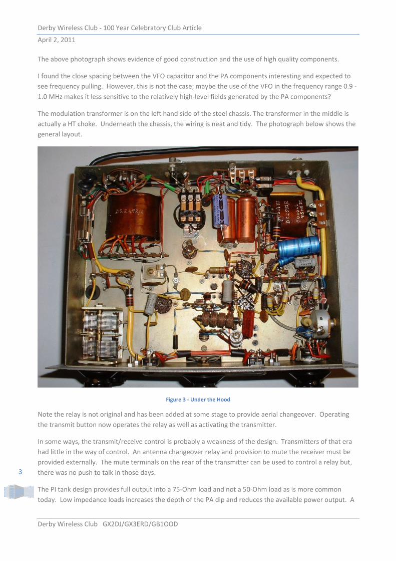
The above photograph shows evidence of good construction and the use of high quality components.
I found the close spacing between the VFO capacitor and the PA components interesting and expected to
see frequency pulling. However, this is not the case; maybe the use of the VFO in the frequency range 0.9 -
1.0 MHz makes it less sensitive to the relatively high-level fields generated by the PA components?
The modulation transformer is on the left hand side of the steel chassis. The transformer in the middle is
actually a HT choke. Underneath the chassis, the wiring is neat and tidy. The photograph below shows the
general layout.
Figure 3 - Under the Hood
Note the relay is not original and has been added at some stage to provide aerial changeover. Operating
the transmit button now operates the relay as well as activating the transmitter.
In some ways, the transmit/receive control is probably a weakness of the design. Transmitters of that era
had little in the way of control. An antenna changeover relay and provision to mute the receiver must be
provided externally. The mute terminals on the rear of the transmitter can be used to control a relay but,
there was no push to talk in those days.
The PI tank design provides full output into a 75-Ohm load and not a 50-Ohm load as is more common
today. Low impedance loads increases the depth of the PA dip and reduces the available power output. A
Derby Wireless Club - 100 Year Celebratory Club Article
April 2, 2011
Derby Wireless Club GX2DJ/GX3ERD/GB1OOD
4
simple trick is to put say 500 - 1000 pF across the output (preferably external to the rig) that allows it to
tune normally. The microphone input is high impedance, which is typical of valve rigs of this vintage. My
Sure 450 series 2 (Looks like a Sure 444) works very well and rolls off above 3 kHz.
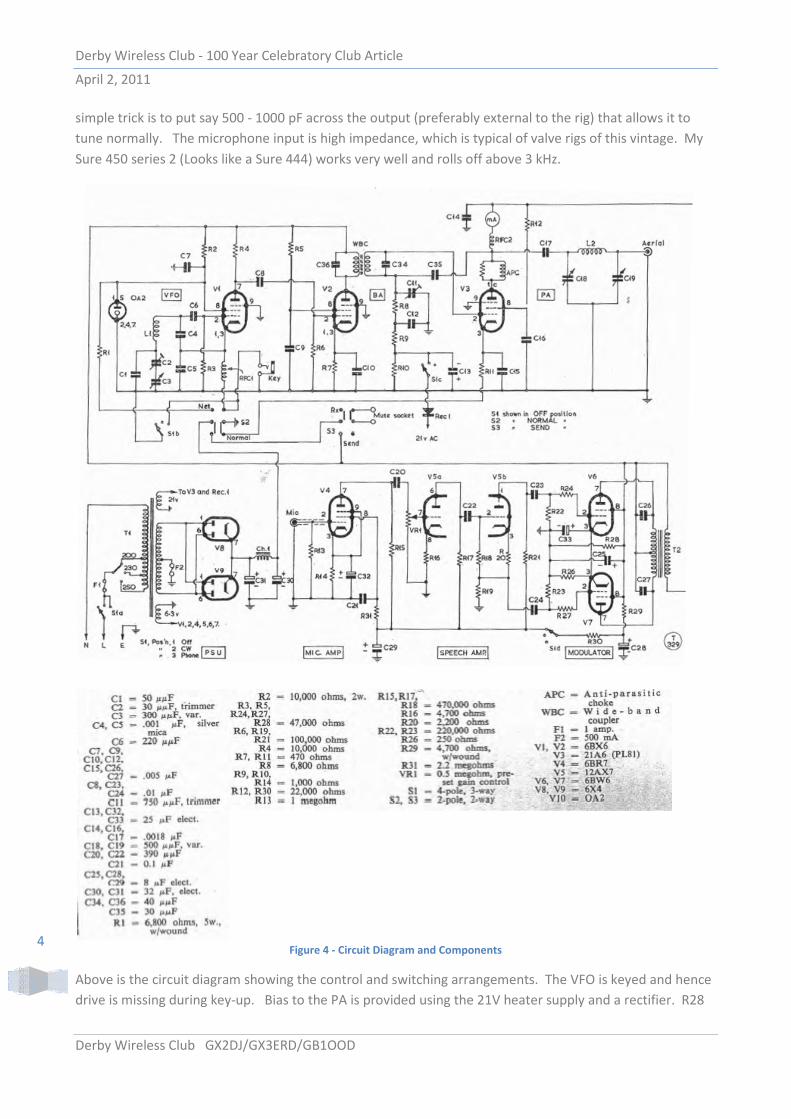
Figure 4 - Circuit Diagram and Components
Above is the circuit diagram showing the control and switching arrangements. The VFO is keyed and hence
drive is missing during key-up. Bias to the PA is provided using the 21V heater supply and a rectifier. R28
Derby Wireless Club - 100 Year Celebratory Club Article
April 2, 2011
Derby Wireless Club GX2DJ/GX3ERD/GB1OOD
5
seems to perform a strange function in the modulator - a 47k resistor connects directly across the HT
supply but only on transmit? The potential divider C35 and C11 provides neutralisation by applying anti-
phase RF to the tuned grid input. Microphone impedance input is set by R13 at 1 MΩ. As with other
transmitters of this vintage, there appears little in the way of upper audio frequency cut-off control; C26
and C27 appear to be the only limit other than transformer losses and the effect of RF decoupling
capacitors.
How Well Does it Work
My KW 160 is at least 40 years old and has probably deteriorated with time. However, it still seems to work
so I decided to apply some simple tests to establish basic performance baselines.
Power Output
This particular KW 160 was fitted with rectifier diodes in place of the two 6X4 rectifiers shown in the
diagram that I presume was a factory modification. On transmit, the HT voltage reached 324V so at 40mA
PA current, the DC input power was around 12 Watts. Output power was measured at 8 Watts suggesting
66% efficiency which is typical for a Class C PA. The transmitter is very sturdy; I accidentally left it on
transmit for several hours without drama or damage. The dummy load was hot but the KW 160 seemed
fine.
Frequency Stability
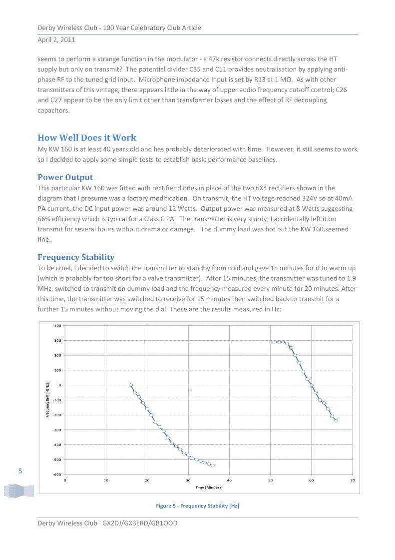
To be cruel, I decided to switch the transmitter to standby from cold and gave 15 minutes for it to warm up
(which is probably far too short for a valve transmitter). After 15 minutes, the transmitter was tuned to 1.9
MHz, switched to transmit on dummy load and the frequency measured every minute for 20 minutes. After
this time, the transmitter was switched to receive for 15 minutes then switched back to transmit for a
further 15 minutes without moving the dial. These are the results measured in Hz:
Figure 5 - Frequency Stability [Hz]
-600
-500
-400
-300
-200
-100
0
100
200
300
400
0 10 20 30 40 50 60 70
Freq
uen
cy D
rift
[H
ert
z]
Time [Minutes]

Derby Wireless Club - 100 Year Celebratory Club Article
April 2, 2011
Derby Wireless Club GX2DJ/GX3ERD/GB1OOD
6
For saying the transmitter is so old and has spent the last 10 years in a garden shed, the stability is very
respectable. After 50 minutes use/warm up, the VFO remained remarkably stable for 4 to 5 minutes during
continuous transmit with only 10Hz drift recorded. After this time, the heat generated by the PA seemed
to permeate into VFO components and the frequency falls steadily at around 100 Hz every few minutes.
This is not surprising behaviour, the PA valve is only inches from the VFO capacitor. The implication is that
with intermittent operation, the frequency stability should be excellent.
Modulation
The key part of an AM transmitter is the modulator so naturally this has come under close scrutiny. KW
used a properly designed modulation transformer incorporating an 8kΩ centre tapped primary winding and
a 5KΩ secondary winding rated at 75mA DC. A pair of push-pull 6BW6s with G2 at 300V should provide
10W output or more. So, can it produce 100% with reasonably distortion?
Figure 6 - Modulation near 100 % and 120% Respectively
As can be seen above, the transmitter can be over-modulated with relative ease if care is not exercised. In
these plots the transmitter ran 12 Watts input and was connected to a dummy load.
Frequency Response and Distortion
The next section looks at the frequency response measured at the microphone socket. It turns out very flat
from a few hundred Hertz to 3 kHz. In fact, at 3 kHz, the audio response was down only 1.8dB. However,
the response was only down 20dB at 11.6 kHz meaning that local stations will detect splatter if a wideband
microphone is used.
The audio response falls at about 12dB/octave up to 15 kHz and then 18dB/octave above this. I am not
sure why things change at 15 kHz but it is probably due to additional core losses in the modulation
transformer.
To be safe, the best way of driving the transmitter is to pre-tailor the audio by using a communications type
microphone or use a mike pre-amp with built in filtering. Ideally, use an Inovonics 222 AM Broadcast audio
processor or equivalent that has the advantage of negative clipping and very loud clear audio. Another,
very practical option is ‘Voice Shaper’ by VE3NEA, which is excellent.

Derby Wireless Club - 100 Year Celebratory Club Article
April 2, 2011
Derby Wireless Club GX2DJ/GX3ERD/GB1OOD
7
Figure 7 - KW160 Audio Frequency Response
Regarding distortion, a 1 kHz audio tone was inserted into the microphone socket and the associated RF
spectrum measured at 30% modulation. The second harmonic at 2 kHz was approximately 30dB down.
Similarly, the third harmonic at 3 kHz was more than 50dB down. This corresponds to around 3 - 4 %
distortion. In mitigation, the oscillator source was not absolutely clean (2nd
Harmonic @ -50dB) and the
audio pre-amplifier (6BR7) was driven rather hard requiring the audio gain on the transmitter to be backed
well off. I suspect with more care and less audio drive, the measured distortion would be lower. With
100% and 120% modulation, the second harmonic remained similar in level but the third harmonic level
increased slightly. Surprisingly, when over modulated, the in-band (0.3 - 3 kHz) distortion remained
reasonable. However, not surprisingly, the out-of-band transmitted signal widened considerably.
The ultimate test is how it sounds on the air. I connected an FM tuner low-level output directly to the
microphone input and connected the transmitter to a dummy load and set the modulation to 90% peak
using Radio 4 as the modulation source. Listening on a FT1000MP and a Drake R8 with 6 kHz bandwidth
was an absolute pleasure. The audio was superb, clear and effortless without any hint of distortion.
Conclusion
Even forty years on, the K.W. “One-Sixty” performs remarkably well and is a real gem. KW really knew how
to design amateur equipment and produced transmitters that both looked good and sounded excellent on
the air. Care is needed to restrict audio bandwidth and aerial changeover is a pain but the rig is still capable
of providing years of service.
Martin, G3SZJ, commented that the KW 160 contains a lot of engineering for a single band QRP 10W AM
rig. He is of course correct; compared with modern equipment, for example the FT 897, which is half the
size, functionality is low. However, perhaps that is the attraction - simplicity. I suspect the KW 160 will still
be serviceable in another 40 years - I am not so sure I can say the same about modern equipment.
73’s
Chris G4AKE
-70
-60
-50
-40
-30
-20
-10
0
10
0.1 1 10
Am
plitu
de [d
B]
Frequency [kHz]
KW 160 Frequency Response