steam turbine seminar -17 open vacuum breaker about 15 minutes for hogging/vacuum pull no corrosion...
TRANSCRIPT
Steam Turbine Seminar -17Lund University
Lund University / LTH / Energy Sciences / TPE / Magnus Genrup / 2017-10-25 Page 2
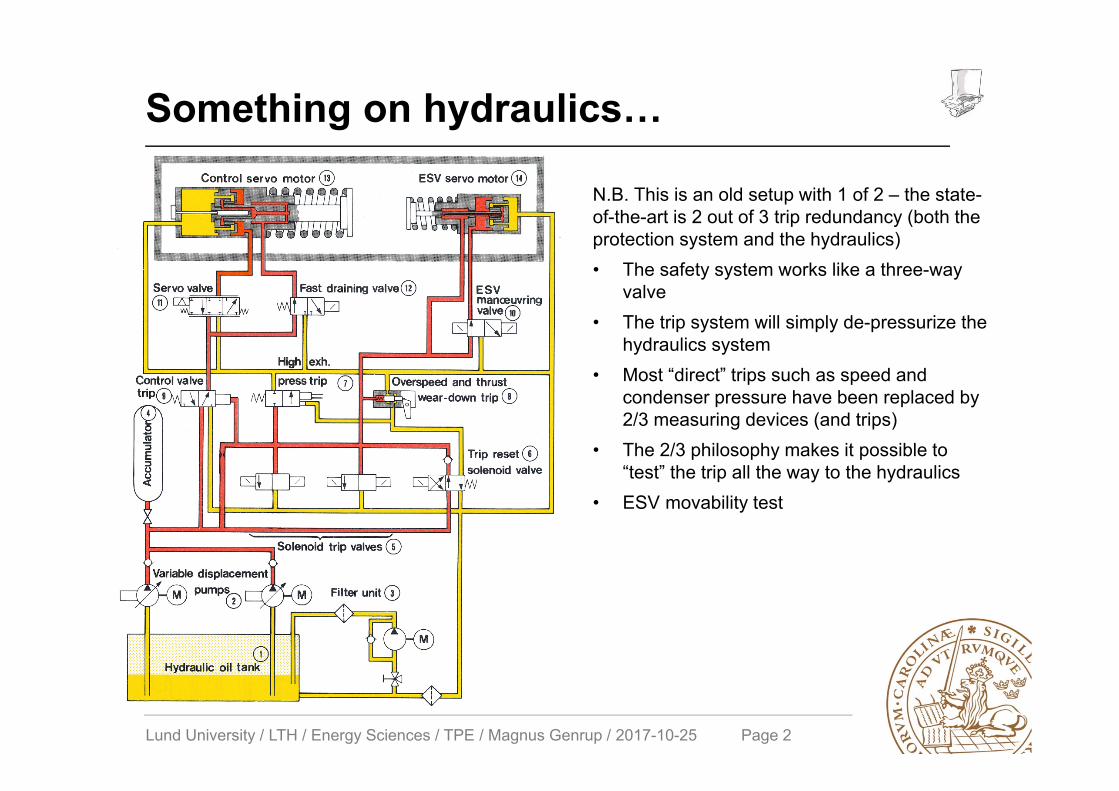
Something on hydraulics…
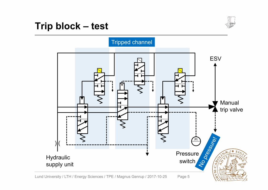
N.B. This is an old setup with 1 of 2 – the state-of-the-art is 2 out of 3 trip redundancy (both the protection system and the hydraulics)• The safety system works like a three-way
valve• The trip system will simply de-pressurize the
hydraulics system• Most “direct” trips such as speed and
condenser pressure have been replaced by 2/3 measuring devices (and trips)
• The 2/3 philosophy makes it possible to “test” the trip all the way to the hydraulics
• ESV movability test
Lund University / LTH / Energy Sciences / TPE / Magnus Genrup / 2017-10-25 Page 3
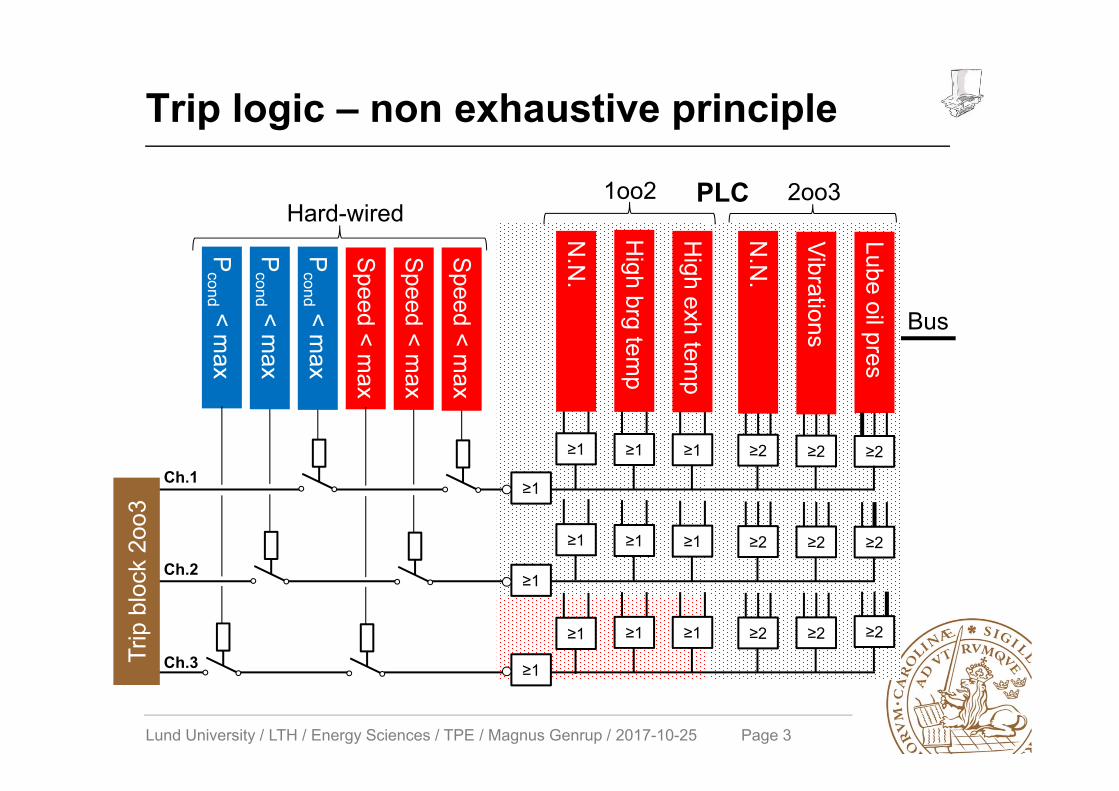
Trip logic – non exhaustive principle
Lube oil pres
≥2
≥2
≥2
≥2
Vibrations
≥2
≥2
≥2
≥2
≥2
N.N
.
≥1H
igh exhtem
p
≥1
≥1
2oo31oo2
≥1
≥1
≥1
High brg
temp
PLC
Bus
≥1
≥1
≥1
N.N
.
Speed <m
ax
Speed < max
Trip
blo
ck 2
oo3
Hard-wired
Speed <m
ax
Pcond < m
ax
Pcond <
max
Pcond < m
ax
Ch.1
Ch.2
Ch.3
≥1
≥1
≥1
Lund University / LTH / Energy Sciences / TPE / Magnus Genrup / 2017-10-25 Page 4
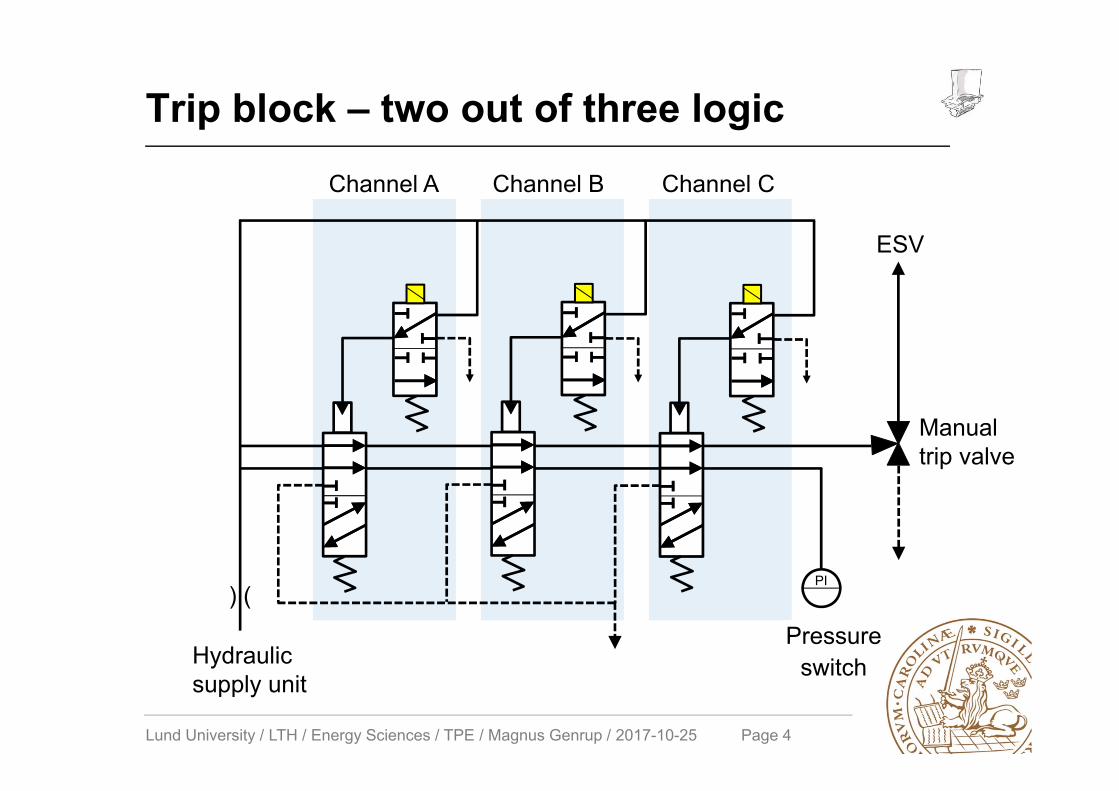
Trip block – two out of three logic
Manual trip valve
Pressure switch
PI
ESV
Hydraulic supply unit
Channel A Channel B Channel C
) (
Lund University / LTH / Energy Sciences / TPE / Magnus Genrup / 2017-10-25 Page 5
Trip block – test
Pressure switch
PI
ESV
Manual trip valve
Hydraulic supply unit
Tripped channel
) (
Lund University / LTH / Energy Sciences / TPE / Magnus Genrup / 2017-10-25 Page 6
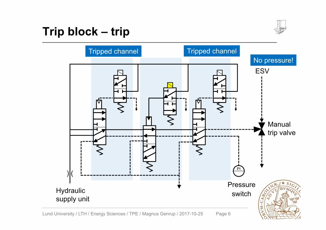
Trip block – trip
Pressure switch
PI
ESV
Manual trip valve
Hydraulic supply unit
Tripped channel Tripped channelNo pressure!
) (

Lund University / LTH / Energy Sciences / TPE / Magnus Genrup / 2017-10-25 Page 7
The ”Duck-Curve”…
4.3 GW/h
California
Sweden
Lund University / LTH / Energy Sciences / TPE / Magnus Genrup / 2017-10-25 Page 8
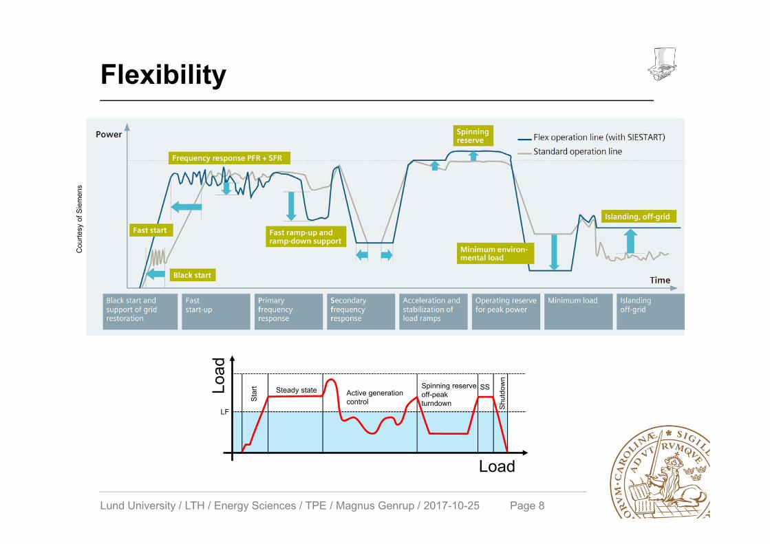
Flexibility
Star
t Steady state Active generation control
Spinning reserve off-peak turndown
SS
Shut
dow
n
Load
LF
Load
Cou
rtesy
of S
iem
ens
Lund University / LTH / Energy Sciences / TPE / Magnus Genrup / 2017-10-25 Page 9
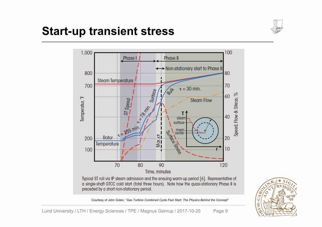
Start-up transient stress
Courtesy of John Gülen, “Gas Turbine Combined Cycle Fast Start: The Physics Behind the Concept”

Lund University / LTH / Energy Sciences / TPE / Magnus Genrup / 2017-10-25 Page 10
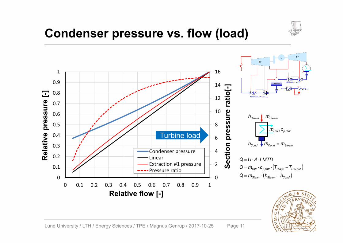
Turbine pressures vs. flow (load)
CondSteamSteam
outCW,inCW,CWp,CW
hhmQ
TTcmQLMTDAUQ
SteamSteam mh
SteamCondCond mmh
CWp,CW c,m
0
0.1
0.2
0.3
0.4
0.5
0.6
0.7
0.8
0.9
1
0 0.1 0.2 0.3 0.4 0.5 0.6 0.7 0.8 0.9 1
Normalised
pressure [‐]
Normalised flow [‐]
Linear CV
Extr #5 Extr #4
Extr #3 Extr #2
Extr #1 Cond
Lund University / LTH / Energy Sciences / TPE / Magnus Genrup / 2017-10-25 Page 11
0
2
4
6
8
10
12
14
16
0
0.1
0.2
0.3
0.4
0.5
0.6
0.7
0.8
0.9
1
0 0.1 0.2 0.3 0.4 0.5 0.6 0.7 0.8 0.9 1
Condenser pressureLinearExtraction #1 pressurePressure ratio
Condenser pressure vs. flow (load)
Relative flow [-]
Rel
ativ
e pr
essu
re [-
]
Sect
ion
pres
sure
ratio
[-]
Turbine load
CondSteamSteam
outCW,inCW,CWp,CW
hhmQ
TTcmQLMTDAUQ
SteamSteam mh
SteamCondCond mmh
CWp,CW c,m
Lund University / LTH / Energy Sciences / TPE / Magnus Genrup / 2017-10-25 Page 12
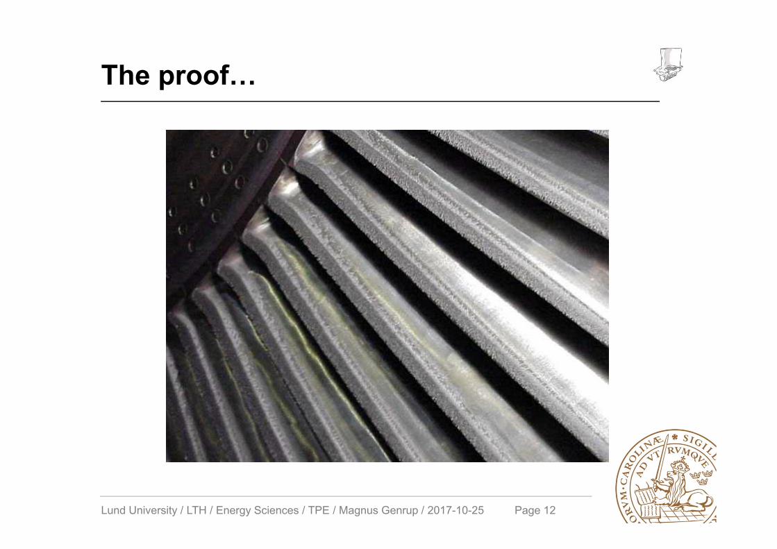
The proof…
Lund University / LTH / Energy Sciences / TPE / Magnus Genrup / 2017-10-25 Page 13
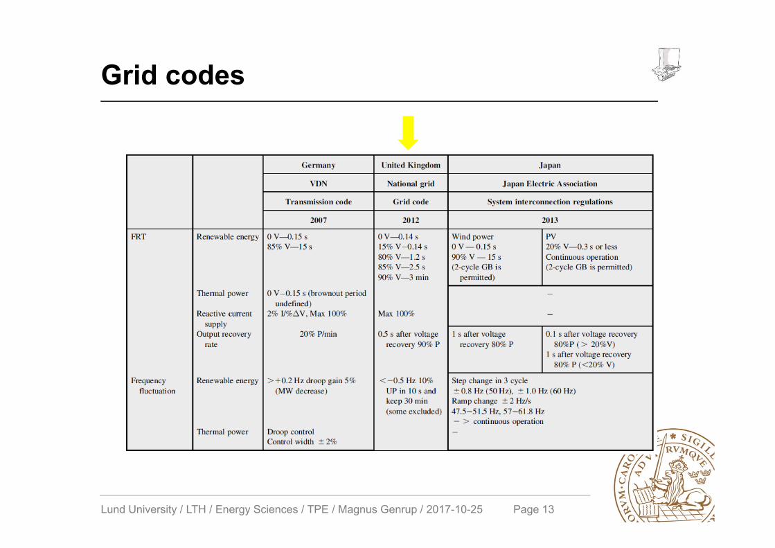
Grid codes
Lund University / LTH / Energy Sciences / TPE / Magnus Genrup / 2017-10-25 Page 14
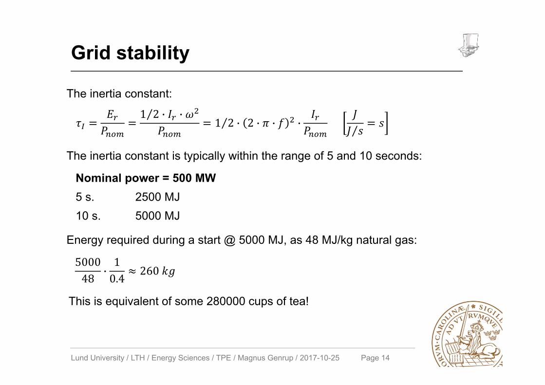
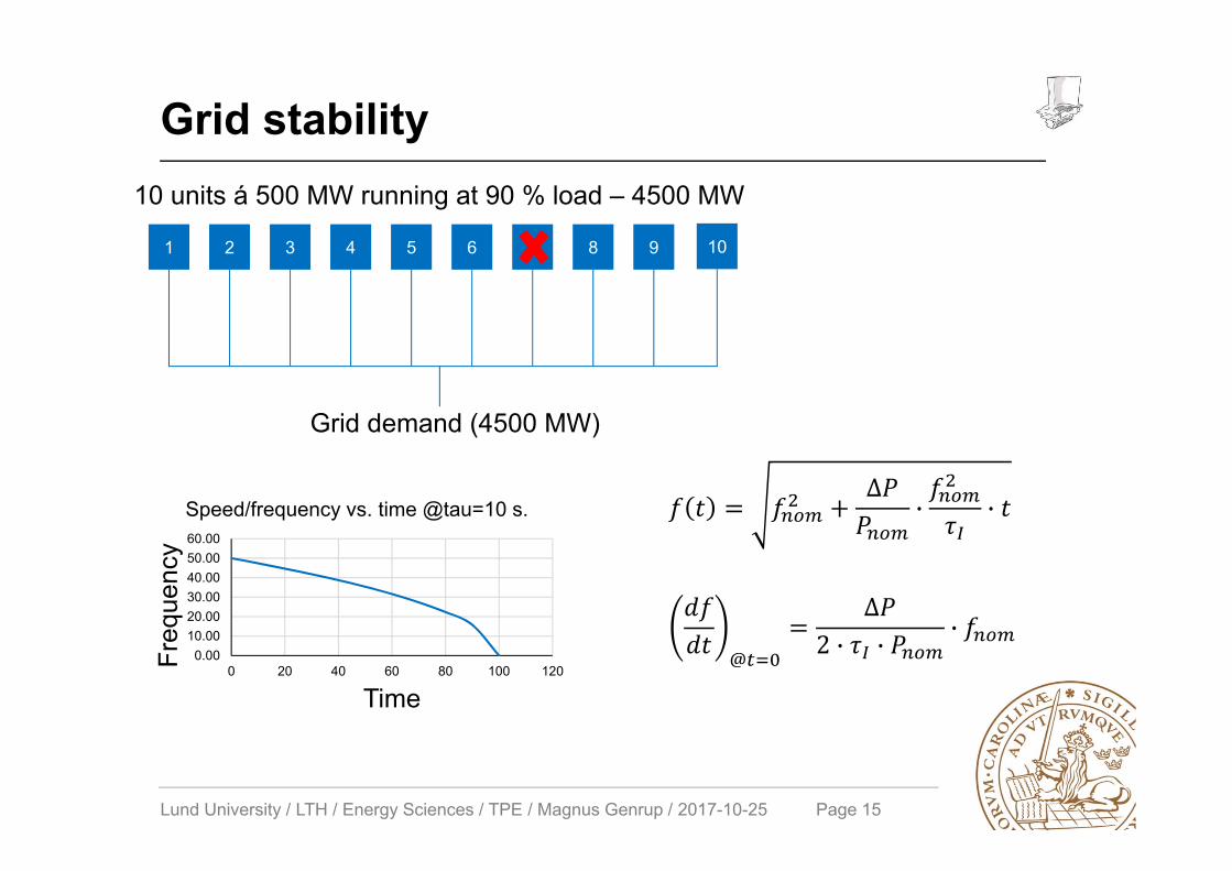
Grid stability
1 2⁄ · ·1 2⁄ · 2 · · · ⁄
The inertia constant:
The inertia constant is typically within the range of 5 and 10 seconds:
Nominal power = 500 MW5 s. 2500 MJ10 s. 5000 MJ
500048 ·
10.4 260
Energy required during a start @ 5000 MJ, as 48 MJ/kg natural gas:
This is equivalent of some 280000 cups of tea!
Lund University / LTH / Energy Sciences / TPE / Magnus Genrup / 2017-10-25 Page 15
Grid stability
1 2 109876543
Grid demand (4500 MW)
10 units á 500 MW running at 90 % load – 4500 MW
∆· ·
0.0010.0020.0030.0040.0050.0060.00
0 20 40 60 80 100 120Freq
uenc
y
Time
Speed/frequency vs. time @tau=10 s.
@
∆2 · · ·
Lund University / LTH / Energy Sciences / TPE / Magnus Genrup / 2017-10-25 Page 16
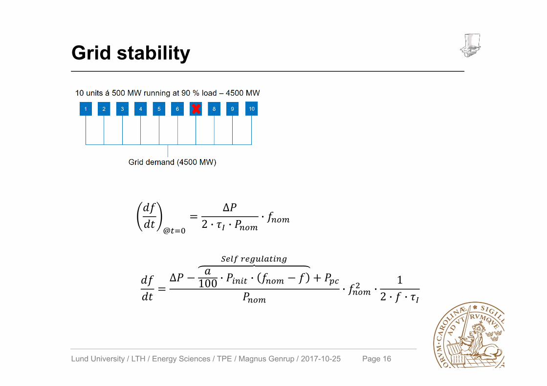
Grid stability
@
∆2 · · ·
∆ 100 · ·
· ·1
2 · ·
Lund University / LTH / Energy Sciences / TPE / Magnus Genrup / 2017-10-25 Page 17
Increased flexibility – starting
• Stress controller– State-of-the
• Blankets– Since the 80s – mature if OEM involved
• Hot air– High initial cost– Very effective
• High-speed barring– Risky…
Lund University / LTH / Energy Sciences / TPE / Magnus Genrup / 2017-10-25 Page 18
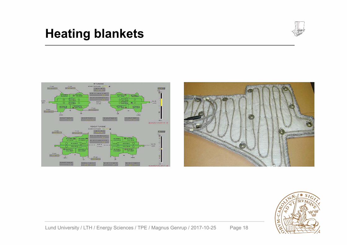
Heating blankets
Lund University / LTH / Energy Sciences / TPE / Magnus Genrup / 2017-10-25 Page 19
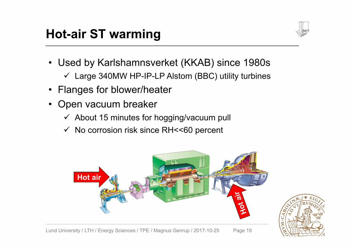
Hot-air ST warming
Hot air
• Used by Karlshamnsverket (KKAB) since 1980s Large 340MW HP-IP-LP Alstom (BBC) utility turbines
• Flanges for blower/heater• Open vacuum breaker
About 15 minutes for hogging/vacuum pull No corrosion risk since RH<<60 percent

Lund University / LTH / Energy Sciences / TPE / Magnus Genrup / 2017-10-25 Page 20
Background
Lund University / LTH / Energy Sciences / TPE / Magnus Genrup / 2017-10-25 Page 21
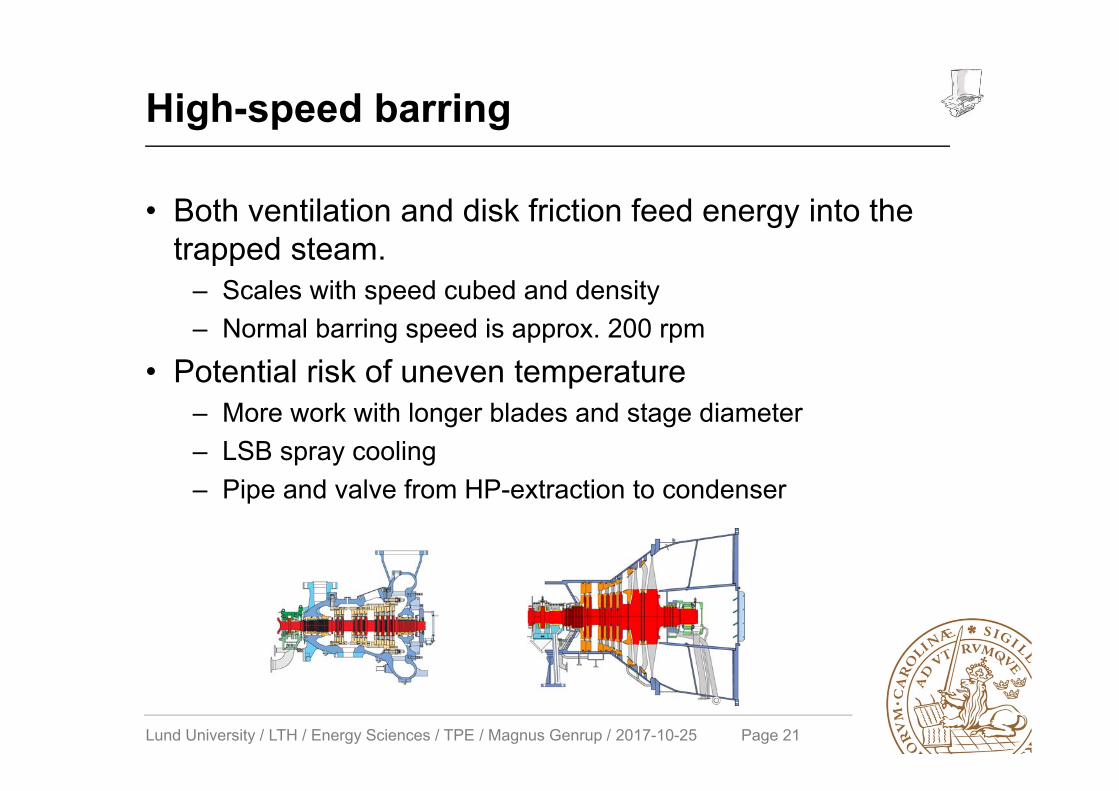
High-speed barring
• Both ventilation and disk friction feed energy into the trapped steam.
– Scales with speed cubed and density– Normal barring speed is approx. 200 rpm
• Potential risk of uneven temperature– More work with longer blades and stage diameter– LSB spray cooling– Pipe and valve from HP-extraction to condenser
Lund University / LTH / Energy Sciences / TPE / Magnus Genrup / 2017-10-25 Page 22
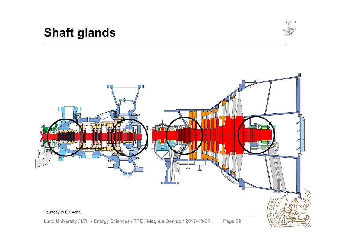
Shaft glands
Courtesy to Siemens
Lund University / LTH / Energy Sciences / TPE / Magnus Genrup / 2017-10-25 Page 23
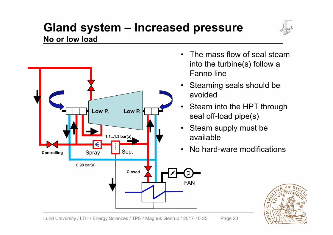
Gland system – Increased pressureNo or low load
FAN
Low P. Low P.
Spray Sep.
1.1...1.3 bar(a)
0.98 bar(a)
Controlling
Closed
• The mass flow of seal steam into the turbine(s) follow a Fanno line
• Steaming seals should be avoided
• Steam into the HPT through seal off-load pipe(s)
• Steam supply must be available
• No hard-ware modifications
Lund University / LTH / Energy Sciences / TPE / Magnus Genrup / 2017-10-25 Page 24
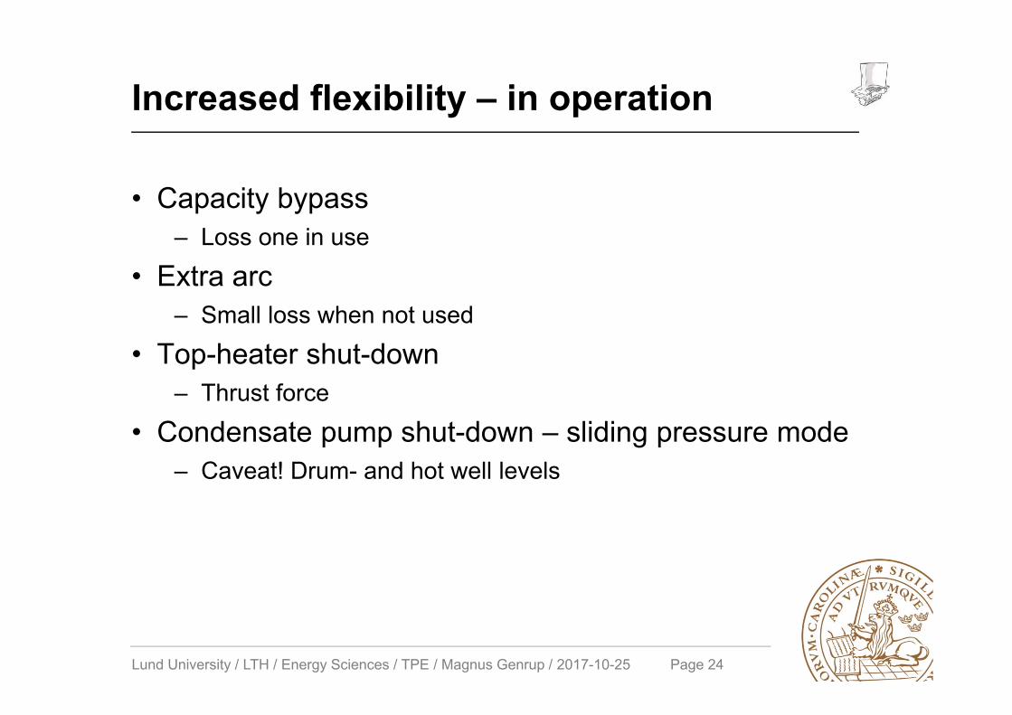
Increased flexibility – in operation
• Capacity bypass– Loss one in use
• Extra arc– Small loss when not used
• Top-heater shut-down– Thrust force
• Condensate pump shut-down – sliding pressure mode– Caveat! Drum- and hot well levels
Lund University / LTH / Energy Sciences / TPE / Magnus Genrup / 2017-10-25 Page 25
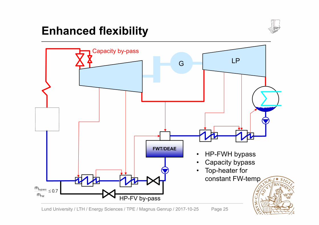
Enhanced flexibility
HP
LPG
FWT/DEAE
Capacity by-pass
HP-FV by-pass0.7
m
m
FW
bypass
• HP-FWH bypass• Capacity bypass• Top-heater for
constant FW-temp
Lund University / LTH / Energy Sciences / TPE / Magnus Genrup / 2017-10-25 Page 26
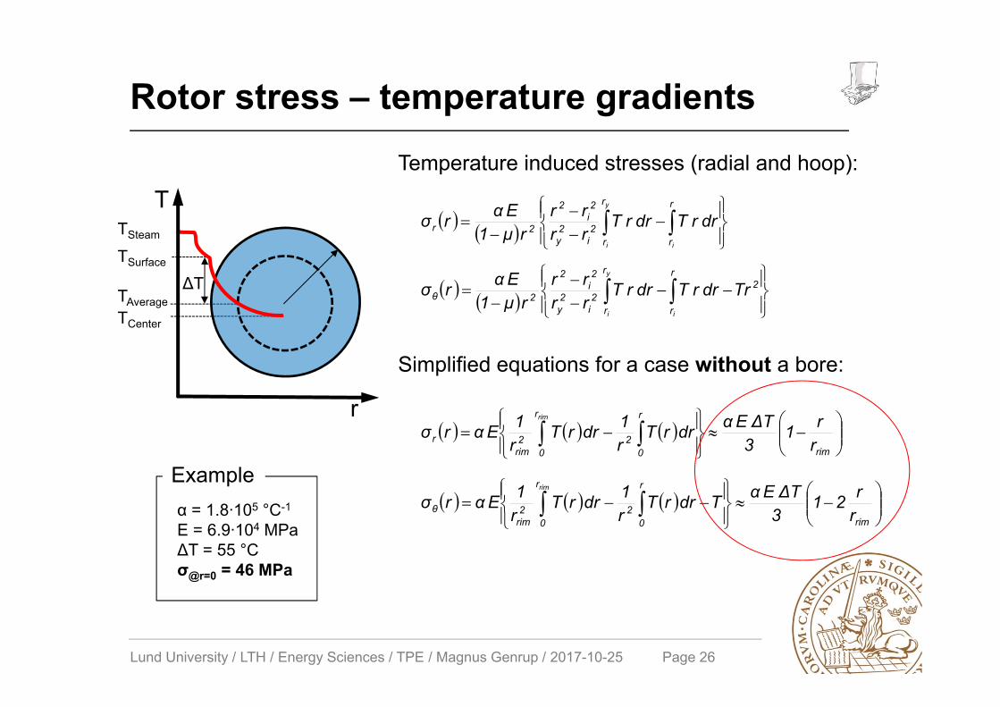
Rotor stress – temperature gradients
T
r
TCenter
TAverage
TSteam
TSurface
ΔT
y
i i
r
r
r
r2
i2y
2i
2
2r drrTdrrTrrrr
rμ1Eαrσ
y
i i
r
r
r
r
22
i2y
2i
2
2θ TrdrrTdrrTrrrr
rμ1Eαrσ
rim
r
0
r
022
rimr r
r13ΔTEαdrrT
r1drrT
r1Eαrσ
rim
rim
r
0
r
022
rimθ r
r213ΔTEαTdrrT
r1drrT
r1Eαrσ
rim
Temperature induced stresses (radial and hoop):
Simplified equations for a case without a bore:
α = 1.8∙105 °C-1
E = 6.9∙104 MPaΔT = 55 °Cσ@r=0 = 46 MPa
Example
Lund University / LTH / Energy Sciences / TPE / Magnus Genrup / 2017-10-25 Page 27
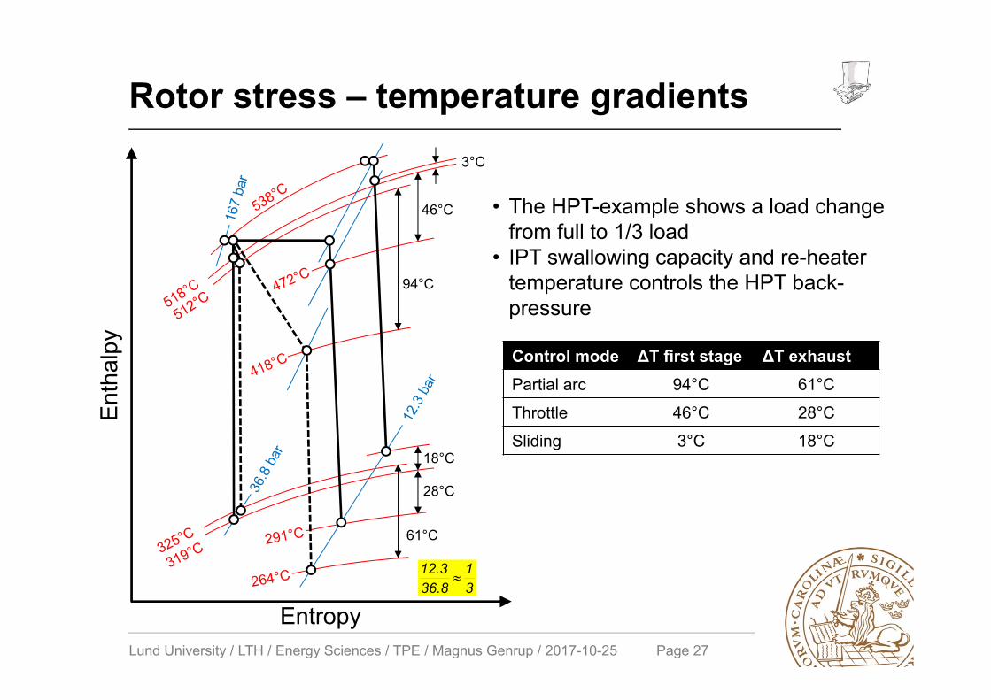
Rotor stress – temperature gradients
Control mode ΔT first stage ΔT exhaustPartial arc 94°C 61°C
Throttle 46°C 28°C
Sliding 3°C 18°C
• The HPT-example shows a load change from full to 1/3 load
• IPT swallowing capacity and re-heater temperature controls the HPT back-pressure
3°C
46°C
94°C
18°C
28°C
61°C
Enth
alpy
Entropy31
36.812.3

Lund University / LTH / Energy Sciences / TPE / Magnus Genrup / 2017-10-25 Page 28
Fatigue – low or high?
Life cycles, [n]
Stre
ss a
mpl
itude
, [σ a
]
Low-cycle fatigue High-cycle fatigue
Fatigue limit
σσa
σa
Time
Stre
ss
Failure
No failure – no crack initiation
105…7
Wöhler- or σ,N curve
Base
d on
Tan
uma
& Ta
dash
i, “A
dvan
ces
in S
team
Tur
bine
s fo
r Mod
ern
Pow
er P
lant
s”
Lund University / LTH / Energy Sciences / TPE / Magnus Genrup / 2017-10-25 Page 29
Casing wall temperature probe
Lund University / LTH / Energy Sciences / TPE / Magnus Genrup / 2017-10-25 Page 30
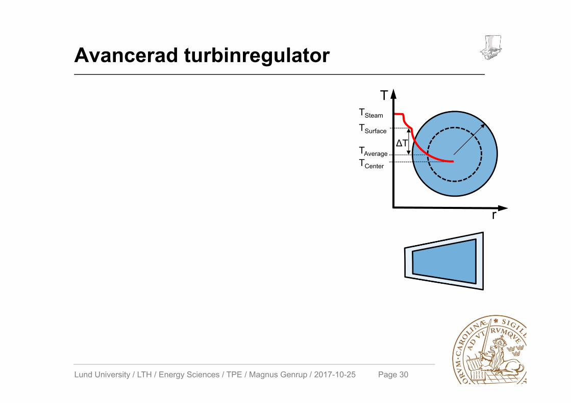
Avancerad turbinregulator
T
r
TCenter
TAverage
TSteam
TSurface
ΔT

Lund University / LTH / Energy Sciences / TPE / Magnus Genrup / 2017-10-25 Page 31
Aged deterioration – failures M
ater
ial
Perf
orm
ance
Creep
Embrittlement
Fatigue
Environment assisted crack
Thermal fatigue
Low-cycle fatigue
Fretting
Dynamic SCC*
Static SCC*
Corrosion fatigue
Crack
Crack
Crack
Crack
Crack
Crack
Crack
Brittle fracture
Softening
Creep
Wear/rubbing
Erosion/FAC
Scale deposition
Type of deterioration Mode of deterioration Damage or incidence
Loosening
Deformation
Efficiency decrease
Efficiency decrease
Efficiency decrease, stick, rubbing
HP/IP shroud, blade groove, HP/IP casing, main pipes, main valves
HP/IP rotor
HP/IP heat groove, bottom of blade root groove
LP last blades groove of LP rotor, HP/IP casings
HP/IP blade groove of rotor
Blade groove of LP rotor
Blade groove of LP rotor
Blade root and groove, shroud and profile
Casing bolts (high temperature)
HP/IP diaphragm nozzle plate (impulse), HP/IP rotor and inner casings (leak)
Seals, bearings, valve shafts
Control stage nozzle and LP last stages
HP/IP nozzles and blades, main valves
Typical damaged portion
*Stress corrosion cracking
Base
d on
Tan
uma
& Ta
dash
i, “A
dvan
ces
in S
team
Tur
bine
s fo
r Mod
ern
Pow
er P
lant
s”
Lund University / LTH / Energy Sciences / TPE / Magnus Genrup / 2017-10-25 Page 32
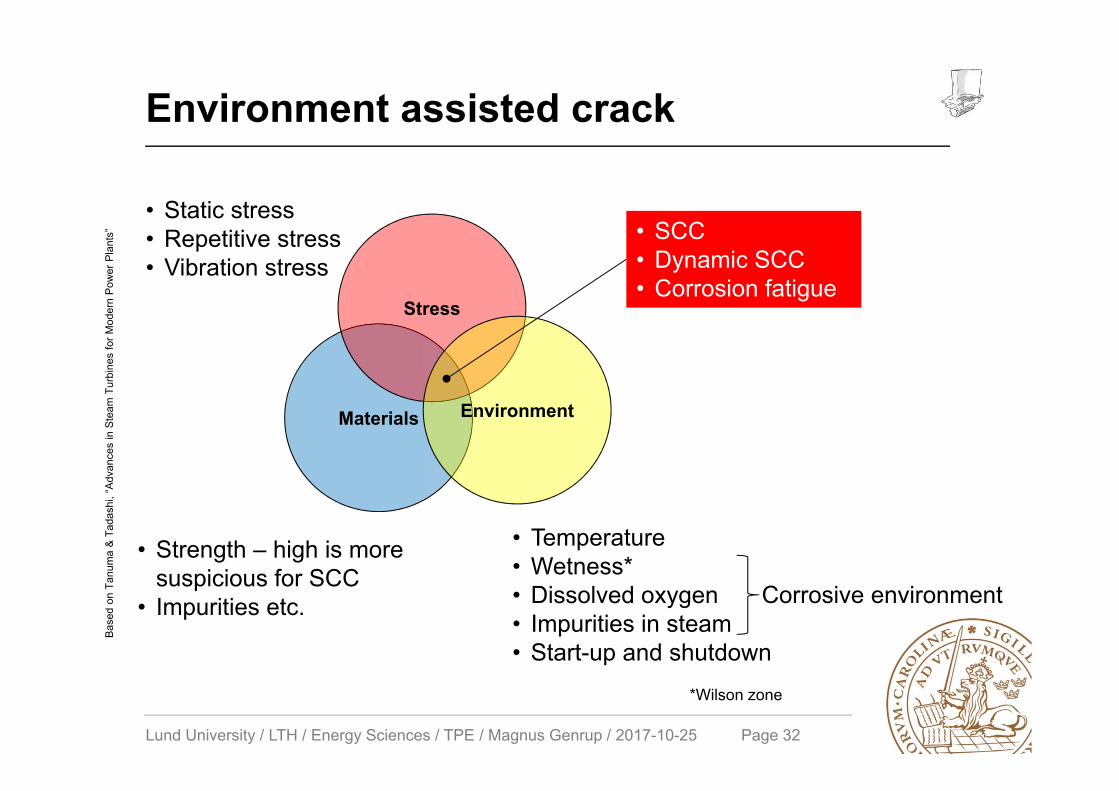
Environment assisted crack
Corrosive environment
Materials
Stress
Environment
• SCC• Dynamic SCC• Corrosion fatigue
• Static stress• Repetitive stress• Vibration stress
• Strength – high is more suspicious for SCC
• Impurities etc.
• Temperature• Wetness*• Dissolved oxygen• Impurities in steam• Start-up and shutdown
*Wilson zone
Base
d on
Tan
uma
& Ta
dash
i, “A
dvan
ces
in S
team
Tur
bine
s fo
r Mod
ern
Pow
er P
lant
s”
Lund University / LTH / Energy Sciences / TPE / Magnus Genrup / 2017-10-25 Page 33
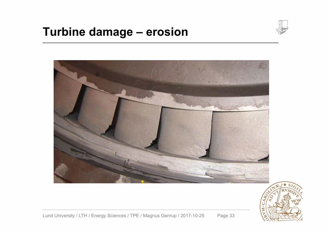
Turbine damage – erosion

Lund University / LTH / Energy Sciences / TPE / Magnus Genrup / 2017-10-25 Page 34
Solid particle erosion (SPE)
Ken Cotton, ”Evaluating and Improving Steam Turbine Performance”, 2nd ed.
N.B. This is a very design specific problem!!!
Lund University / LTH / Energy Sciences / TPE / Magnus Genrup / 2017-10-25 Page 35
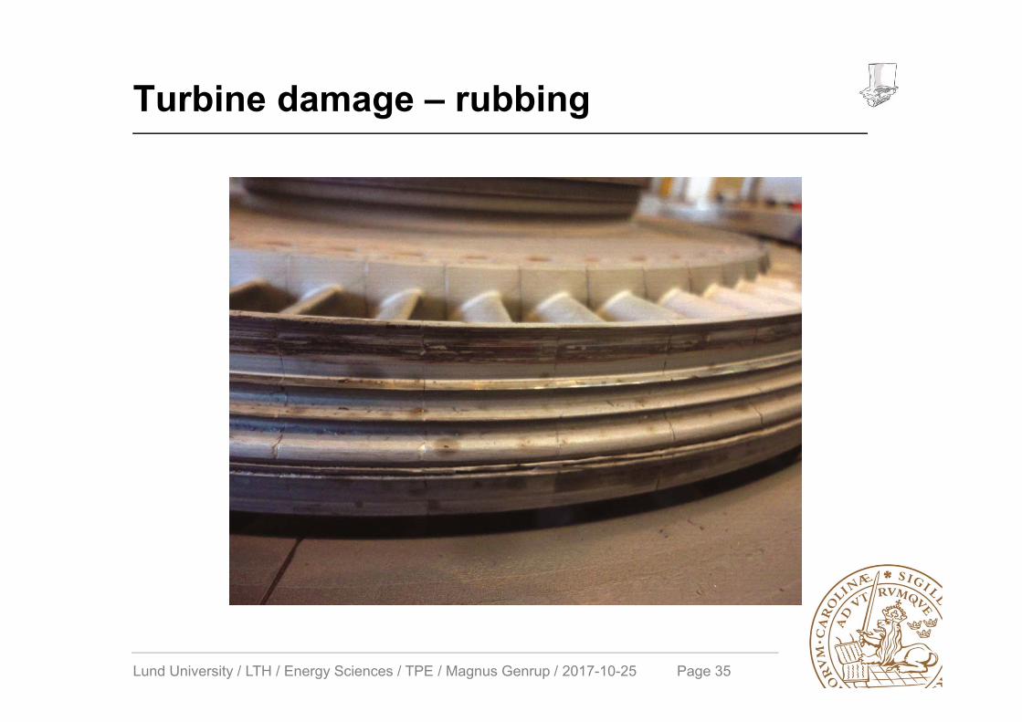
Turbine damage – rubbing