seismic analysis of partially-grouted reinforced …flm72/flmoon_files/final report 4...seismic...
TRANSCRIPT
Seismic Analysis of Partially-Grouted Reinforced Masonry Walls Constructed Using Masonry Cement Mortar
(PCA Index No. 03-12)
by
A.A. Hamid and F.L. Moon
Drexel University Department of Civil, Architectural and Environmental Engineering
3141 Chestnut St. Philadelphia, PA 19104
12 April 2005
ii
EXECUTIVE SUMMARY
Since the establishment of ASTM standard C91, masonry cement mortars have become
widely used for masonry construction in low to moderate seismic regions. However, the
Masonry Standards Joint Committee Code prohibits the use of masonry cement mortars
in lateral force resisting systems for structures that fall into Seismic Design Categories D,
E, and F. The general objective of this study is to examine the appropriateness of this
restriction in light of past research and, if necessary, propose additional research required
to fill any existing knowledge gap.
Since information about the specific impact of the physical and mechanical properties of
masonry cement mortars on the seismic response of masonry shear walls is limited, this
report primarily focuses on research that has identified the influence of mortar on the
behavior of masonry assemblages. In particular, the influence of mortar type is examined
in terms of in-plane pier response, out-of-plane wall response, and the response of
masonry assemblages under axial compression, flexural tension, bed joint shear and
diagonal tension. The primary gap identified through this literature review was the lack of
experimental research that addressed the response of reinforced masonry shear walls
constructed with masonry cement mortar. To establish a comprehensive and efficient
research program to fill this gap, the available literature related to the behavior of
partially grouted reinforced masonry shear walls was also reviewed and key factors that
influence response were established.
Based on this literature survey, it is the authors’ opinion that the use of masonry cement
mortar instead of portland cement lime mortar will not have a detrimental effect on the
strength and deformation capacity of grouted and partially grouted (up to a spacing of 48
in.) reinforced masonry walls subjected to in-plane and out-of-plane loadings. However,
it must be emphasized that the evidence supporting this conclusion for in-plane loading is
limited to investigations of assemblage behavior and a single in-plane pier experimental
study. As a result, the report concludes with an outline of a proposed in-plane testing
program aimed at filling this knowledge gap.
iii
TABLE OF CONTENTS
EXECUTIVE SUMMARY…………………………………………………………….. ii 1. INTRODUCTION…………………………………………………………………... 1
1.1 Background…………………………………………………………………... 1
1.2 Reinforced Masonry Walls……………………………………………........... 2
1.3 Development of Mortar…………………………………………………..….. 4
1.4 Seismic Provisions Related to Mortar Type………………………................. 5
1.5 Objective and Scope…………………………………………………………. 6
1.6 Outline of Report…………………………………………………………….. 6
2. EFFECT OF MORTAR TYPE ON THE PROPERTIES MASONRY
ASSEMBLAGES…………………………………………………………………… 7
2.1 Introduction………………………………………………………………….. 7
2.2 Compressive Strength………………………………………………………... 7
2.3 Bond Strength………………………………………..………………………. 9
2.4 Diagonal Tensile Strength…………………………..……………………… 11
2.5 Summary………………………………………….………………………... 12
3. EFFECT OF MORTAR TYPE ON THE PROPERTIES OF MASONRY
WALLS………………..…………………………………………………………….. 14
3.1 Introduction………………………………………………………………… 14
3.2 In-plane Behavior………………………………..…………………………. 14
3.3 Out-of-plane Behavior………………………………………………………17
3.4 Summary…………………………………………………………………… 20
4. EFFECT OF GROUTING ON THE PROPERTIES OF MASONRY
ASSEMBLAGES……..…………………………………………………………….. 22
4.1 Introduction………………………………………………………………… 22
iv
4.2 Compressive Strength…………………………………………………….... 22
4.3 Bed-joint Shear Strength…………………………………………………… 24
4.4 Tensile Strength…………………………………………………………… 25
4.5 Summary…………………………………………………………………… 27
5. IN-PLANE BEHAVIOR OF PARTIALLY GROUTED MASONRY SHEAR
WALLS…………………………………………………………………………….. 29
5.1 Introduction………………………………………………………………… 29
5.2 Review of Past Research…………………………………………………… 29
5.3 Summary…………………………………………………………………… 45
6. CONCLUSIONS……………………………………………………………………. 47 7. REFERENCES……………………………………………………………………... 48
1
1. INTRODUCTION
1.1 Background
Masonry is one of the oldest construction materials employed by man as evident from the
historic remains of the Egyptians and the Greeks. The first masonry was a crude stack of
selected natural stones often with earthen mortar packed between them. This type of
massive masonry could resist large compressive forces and was quite durable, although
its tensile strength was poor. As a result, traditional masonry buildings exploited the
weight of the floors and the massive walls to offset tensile stresses that arose due to
eccentric vertical and lateral loads. Due to its constructability and substantial durability,
construction using this type of masonry (termed UnReinforced Masonry [URM]) was
widespread throughout the 19th Century in the United States. However, a series of
earthquakes around the turn of the century, including the 1886 Charleston, 1906 San
Francisco, 1925 Santa Barbara, and the 1933 Long Beach earthquakes, clearly illustrated
the seismic vulnerability of URM structures. These events prompted the 1933 passage of
the California Field Act, which banned the use of URM for public buildings in California.
This ban was subsequently adopted by other western states; thus, URM construction was
effectively halted west of the Rocky Mountains.
This restriction has led engineers and builders to seek a more ductile, earthquake resistant
form of masonry construction for high seismic regions. Along with economic concerns,
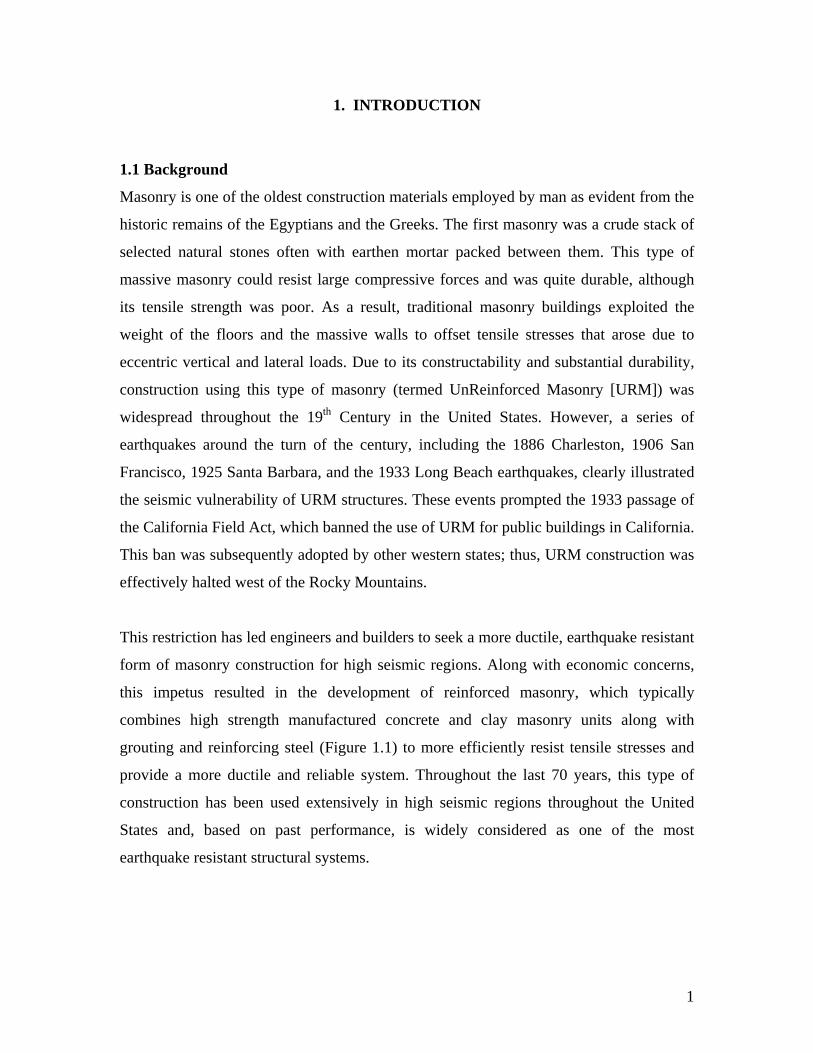
this impetus resulted in the development of reinforced masonry, which typically
combines high strength manufactured concrete and clay masonry units along with
grouting and reinforcing steel (Figure 1.1) to more efficiently resist tensile stresses and
provide a more ductile and reliable system. Throughout the last 70 years, this type of
construction has been used extensively in high seismic regions throughout the United
States and, based on past performance, is widely considered as one of the most
earthquake resistant structural systems.
2
1.2 Reinforced Masonry Walls
In general, both clay and concrete masonry construction have been widely used in the
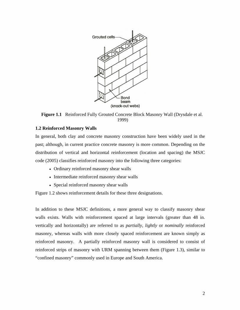
past; although, in current practice concrete masonry is more common. Depending on the
distribution of vertical and horizontal reinforcement (location and spacing) the MSJC
code (2005) classifies reinforced masonry into the following three categories:
• Ordinary reinforced masonry shear walls
• Intermediate reinforced masonry shear walls
• Special reinforced masonry shear walls
Figure 1.2 shows reinforcement details for these three designations.
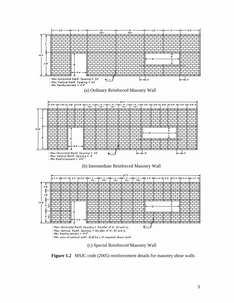
In addition to these MSJC definitions, a more general way to classify masonry shear
walls exists. Walls with reinforcement spaced at large intervals (greater than 48 in.
vertically and horizontally) are referred to as partially, lightly or nominally reinforced
masonry, whereas walls with more closely spaced reinforcement are known simply as
reinforced masonry. A partially reinforced masonry wall is considered to consist of
reinforced strips of masonry with URM spanning between them (Figure 1.3), similar to
“confined masonry” commonly used in Europe and South America.
Figure 1.1 Reinforced Fully Grouted Concrete Block Masonry Wall (Drysdale et al. 1999)
3
(c) Special Reinforced Masonry Wall
Figure 1.2 MSJC code (2005) reinforcement details for masonry shear walls
(a) Ordinary Reinforced Masonry Wall
(b) Intermediate Reinforced Masonry Wall
4
In addition to the distribution of reinforcing steel, reinforced masonry walls can also be
distinguished based on the extent of grouting. Partially grouted masonry walls typically
only have grout placed where reinforcement is located whereas fully grouted masonry
walls have grout placed in every cell. From a construction standpoint, partially grouted
masonry (with grouted cells spaced at larger than 24 in.) is more efficient. For example, it
enables easier installation of services (in ungrouted cells), faster construction, material
savings, and reduced weight (resulting in reduced seismic loads) compared with fully
grouted walls. However, from a behavior standpoint, fully grouted walls are superior
since grouting has been shown to reduce the inherent variability in masonry and also
improve the tensile and shear strength.
1.3 Development of Mortar
Early mortars were primarily used to fill cracks and provide uniform bedding for
masonry units. Such mortars were typically composed of clay, bitumen, or clay-straw
mixtures (Dysdale et al. 1999). Following centuries of lime mortar use in masonry
construction, portland cement-lime mortars were developed to be suitable for particular
applications in the late 1800’s and early 1900’s (Speweik 1995). More recently, masonry
cement mortars have been introduced in the market. Masonry cement is primarily
composed of portland cement or blended hydraulic cement and plasticizing materials. In
addition, other materials are often added to improve properties such as workability,
Figure 1.3 Partially reinforced masonry walls (Drysdale et al. 1999)
5
setting time, and durability. Aside from these improved properties, the primary advantage
of masonry cement is that it is proportioned in controlled conditions which greatly
enhance its uniformity. This alleviates the need for on-site mixing of portland cement and
lime and results in savings in construction time as well as more reliable mix proportions.
Since the establishment of the ASTM standard C91 for these products in 1932, masonry
cement mortars have become widely used in masonry construction in regions of low to
moderate seismicity (Speweik 1995).
1.4 Seismic Provisions Related to Mortar Type
Currently, the Masonry Standards Joint Committee (MSJC) Code (2005) prohibits the use
of MC mortars in the construction of lateral force resisting systems for structures that fall
into Seismic Design Categories (SDC) D, E, and F. Two factors have likely contributed
to establishing and maintaining this ban: (1) MC mortars were not common in high
seismic regions where seismic codes were developed and (2) research into the behaviour
of ungrouted (solid or hollow) masonry assemblages has shown that MC mortars
typically display lower bond strength than PCL mortars. Clearly the first factor is social
in nature rather than related to the actual seismic performance of shear walls constructed
with masonry cements. The second factor, while well established, may not have as large
an influence on seismic performance as expected. Consider that for SDC D, E, and F, all
masonry is required to be reinforced and either partially or fully grouted (the MSJC Code
requires a maximum horizontal and vertical reinforcement spacing of 1220 mm [48 in.]).
According to past research, as the extent of grouting and reinforcement increases, the
influence of mortar type and mortar unit bond diminishes (Drysdale et al. 1999). This
phenomenon is attributed to the continuity across the weak bed-joint plane, and the
additional load path provided by the grouted cells and reinforcement. As a result, it is
generally accepted that for fully grouted masonry this provision is overly restrictive;
however, it is unclear at what level, if any, of partially grouted reinforced masonry this
restriction is appropriate.
6
1.5 Objective and Scope
The study reported herein had two primary objectives. The first was to summarize the
available literature that addresses the influence of mortar type and grouting on the
behavior of masonry elements. This included investigations on masonry assemblages
under axial compression, diagonal tension, and flexural tension, and masonry
components (piers and walls) under in-plane and out-of-plane loads. Close attention was
paid to how the mortar type and extent of grouting affect the properties and the response
of masonry to load. The second objective involved evaluating the validity of the code
restriction (in light of past research) and recommending future research required to fill in
any identified knowledge gaps that may be preserving this ban. The primary gap
identified throughout the literature review was the lack of experimental research that
addressed the response of partially grouted, reinforced masonry shear walls constructed
with MC mortar. To establish a comprehensive and efficient research program to fill this
gap, the available literature related to the behavior of partially grouted reinforced
masonry shear walls was reviewed and key factors that influence response were
established.
1.6 Outline of Report
The report is organized into six sections. Section 2 outlines past research into the effect of
mortar type (MC versus PCL) on the mechanical properties of masonry assemblages. The
literature available on the effect of mortar type on component response is summarized in
Section 3. Section 4 summarizes the available literature on the effect of grouting on the
response of masonry assemblages and Section 5 reviews the literature available on the
response of partially grouted reinforced masonry shear walls. The conclusions of the
study are summarized in Section 6.
7
2. EFFECT OF MORTAR TYPE ON THE PROPERTIES OF MASONRY
ASSEMBLAGES
2.1 Introduction
This section briefly outlines past research that addressed the difference between MC and
PCL lime mortar in regards to the response of masonry assemblages under compression,
flexural tension, and diagonal tension. The large size required to investigate the response
of partially grouted masonry typically precludes the use of masonry assemblages.
Therefore the literature regarding the effect of mortar type on the properties of hollow
and fully grouted assemblages was summarized. The behavior of partially grouted
masonry, depending on spacing of grouted cells, falls between that of hollow and fully
grouted masonry. The MSJC code allows linear interpolation between these two extreme
conditions.
2.2 Compressive Strength
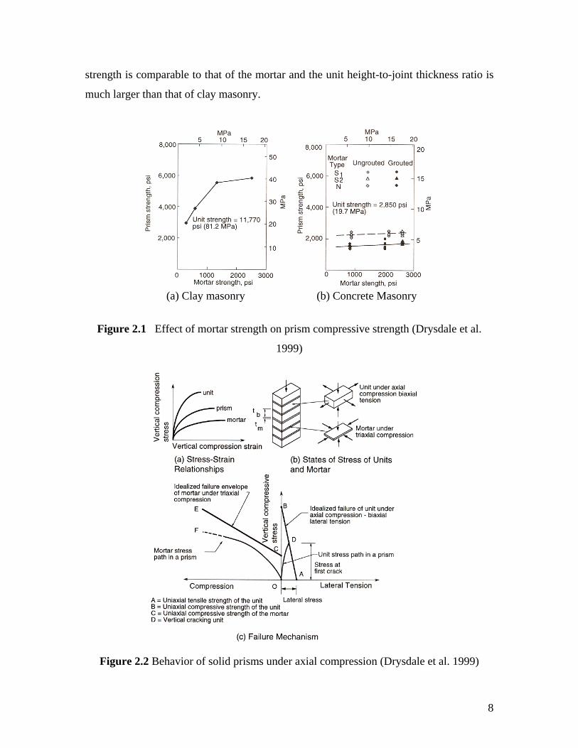
Drysdale et al. (1999) discussed the effect of mortar type on the compressive strength of
ungrouted clay and concrete masonry prisms. The experimental results showed that for
both clay and concrete masonry the mortar properties influenced the compressive
strength; however, this influence was far more pronounced for clay masonry (Figure 2.1).
The effect was attributed to the lateral expansion of the mortar under uniaxial
compression which places the units in biaxial tension transverse to the applied load
(Figure 2.2). Two critical factors that affect the interaction of masonry units and mortar
joints, and explain the increased sensitivity of clay masonry, were identified: relative
unit-joint strength and relative unit height to joint thickness. In the case of clay masonry,
the large differences in unit and mortar strength (i.e. a high unit-to-joint strength ratio)
resulted in a larger differential lateral expansion between the unit and mortar, and in turn
increased the biaxial tension stress in the unit. In addition, in clay masonry the unit
height-to-joint thickness ratio is typically small and thus larger biaxial tension stresses
develop within a given prism height. The lower sensitivity of concrete masonry
compressive strength to mortar properties was attributed to the fact that concrete unit
8
strength is comparable to that of the mortar and the unit height-to-joint thickness ratio is
much larger than that of clay masonry.
Figure 2.1 Effect of mortar strength on prism compressive strength (Drysdale et al.
1999)
Figure 2.2 Behavior of solid prisms under axial compression (Drysdale et al. 1999)
(a) Clay masonry (b) Concrete Masonry
9
2.3 Bond Strength
The influence of mortar on the bond strength of masonry has been investigated by several
researchers. Matthys (1992) investigated the difference between the bond strength of
ungrouted clay masonry constructed with MC and PCL mortars. This investigation tested
prisms constructed of both cored and solid clay masonry units according to ASTM
C1072-86 to determine flexural tensile strength. Based on these results, Matthys
concluded that prisms constructed with MC mortar displayed lower tensile strength than
prisms constructed with the corresponding PCL mortar. In addition, the results showed
that the specimens constructed with PCL mortar displayed lower variability than those
constructed with MC mortar.
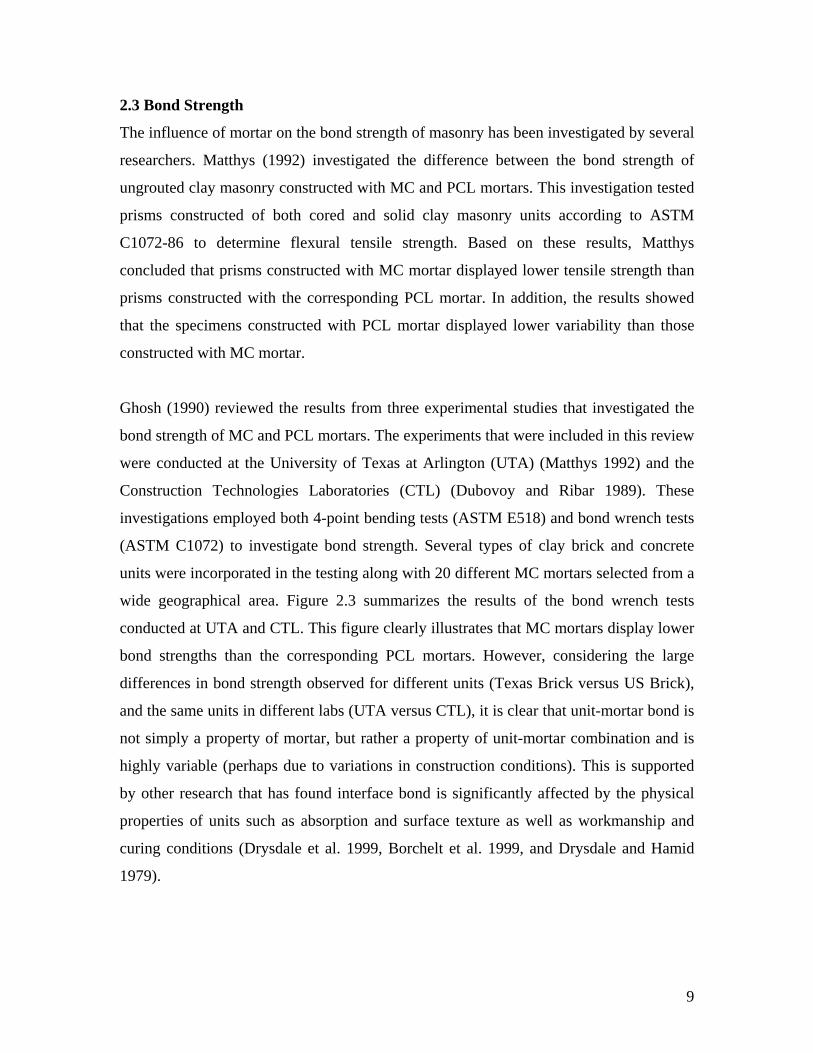
Ghosh (1990) reviewed the results from three experimental studies that investigated the
bond strength of MC and PCL mortars. The experiments that were included in this review
were conducted at the University of Texas at Arlington (UTA) (Matthys 1992) and the
Construction Technologies Laboratories (CTL) (Dubovoy and Ribar 1989). These
investigations employed both 4-point bending tests (ASTM E518) and bond wrench tests
(ASTM C1072) to investigate bond strength. Several types of clay brick and concrete
units were incorporated in the testing along with 20 different MC mortars selected from a
wide geographical area. Figure 2.3 summarizes the results of the bond wrench tests
conducted at UTA and CTL. This figure clearly illustrates that MC mortars display lower
bond strengths than the corresponding PCL mortars. However, considering the large
differences in bond strength observed for different units (Texas Brick versus US Brick),
and the same units in different labs (UTA versus CTL), it is clear that unit-mortar bond is
not simply a property of mortar, but rather a property of unit-mortar combination and is
highly variable (perhaps due to variations in construction conditions). This is supported
by other research that has found interface bond is significantly affected by the physical
properties of units such as absorption and surface texture as well as workmanship and
curing conditions (Drysdale et al. 1999, Borchelt et al. 1999, and Drysdale and Hamid
1979).
10
Figure 2.3. Flexural bond strength of clay masonry (Ghosh 1990)
Using the experimental studies discussed by Ghosh as well as additional testing
conducted at the National Concrete Masonry Association’s (NCMA) Laboratory;
Melander et al. (1993) reported an investigation aimed at establishing the characteristic
bond strength of MC mortar relative to bond strength of PCL mortar established in a
previous study (Hedstrom et al. 1991). Based on the data sets obtained from UTA, CTL,
and NCMA, the authors concluded that the characteristic bond strength of MC mortar
was approximately 0.48 MPa (69 psi) for Type S and 0.30 MPa (44 psi) for Type N.
Comparing with the bond strengths of PCL mortars, it was concluded that reduction
factors of 0.6 and 0.5 be applied to the allowable bond strengths of Type S and Type N
PCL mortars, respectively, when MC mortar is used. These factors were later adopted by
the UBC (ICBO 1991) and are currently provided in the MSJC code (2005).
While the majority of the investigations into the different bond strengths displayed by
MC and PCL mortars have focused on ungrouted masonry, Brown and Melander (1999)
studied this issue for fully grouted masonry. This investigation subjected 40 fully grouted
11
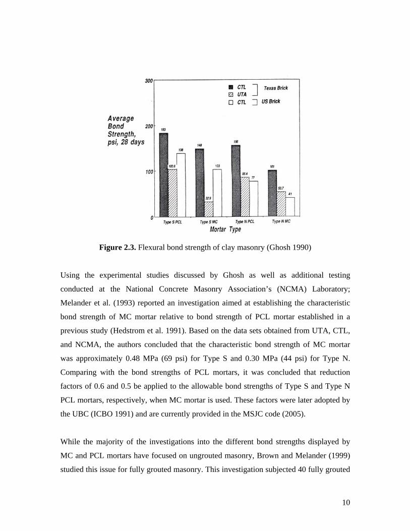
masonry prisms (both clay and concrete) to four-point bending test as per ASTM C1390.
Four types of mortar were investigated: MC Type N, MC Type S, PCL Type N, and PCL
Type S. Figure 2.4 provides a summary of the test results. The authors note that
negligible difference in the flexural tension strength was observed regardless of unit type,
mortar type or whether the mortar was MC or PCL. Based on these results it was
concluded that the flexural tensile strength of grouted prisms normal to the bed joint is
dominated by the grout strength. This study prompted the MSJC code (2005) to increase
the allowable tensile strength perpendicular to the bed-joint for fully grouted masonry
constructed with MC to be more consistent with the allowable tensile strength of PCL
mortar.
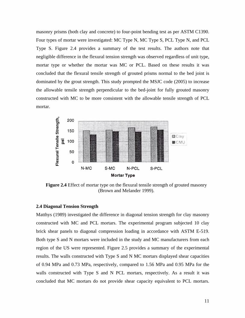
2.4 Diagonal Tension Strength
Matthys (1989) investigated the difference in diagonal tension strength for clay masonry
constructed with MC and PCL mortars. The experimental program subjected 10 clay
brick shear panels to diagonal compression loading in accordance with ASTM E-519.
Both type S and N mortars were included in the study and MC manufacturers from each
region of the US were represented. Figure 2.5 provides a summary of the experimental
results. The walls constructed with Type S and N MC mortars displayed shear capacities
of 0.94 MPa and 0.73 MPa, respectively, compared to 1.56 MPa and 0.95 MPa for the
walls constructed with Type S and N PCL mortars, respectively. As a result it was
concluded that MC mortars do not provide shear capacity equivalent to PCL mortars.
Figure 2.4 Effect of mortar type on the flexural tensile strength of grouted masonry (Brown and Melander 1999).
12
However, it was also pointed out that both MC and PCL mortars provided shear
capacities that greatly exceeded the UBC (ICBO 1988) allowables (0.110 MPa and 0.094
MPa for Type S and N, respectively).
Figure 2.5 Shear strength of (a) Type N mortar panels and (b) Type S mortar panels
(Matthys 1989).
2.5 Summary
The research described in this section focused primarily on the effect of mortar type on
the properties of grouted and ungrouted masonry assemblages. The available literature
showed that the compressive strength of masonry is affected by the properties of mortar.
The primary factors that influence the sensitivity of this effect are the relative unit-joint
strength and the relative unit height to joint thickness. In addition, the literature clearly
demonstrated that MC displays lower bond strength than the corresponding PCL mortar
for ungrouted masonry. In the case of grouted masonry, research has indicated that
negligible differences between the bond strengths of MC and PCL mortar exist due to the
continuity provided by grouted columns. Finally, research has shown that assemblages
(a) (b)
13
built with MC mortar had lower diagonal tension strength than the corresponding
specimens built with PCL mortar for ungrouted clay masonry.
14
3. EFFECT OF MORTAR TYPE ON THE PROPERTIES OF MASONRY WALLS
3.1 Introduction
While masonry assemblages are ideal for providing information about the interactions
between the constituent masonry materials, they have difficulty providing insight into the
response of components, such as walls and piers. This is particularly true for cases of
partially grouted masonry, since it is difficult to obtain the dimensions required to
properly represent partial grouting with assemblages (typically assemblages do not
exceed 4 ft. by 4 ft.). In addition, the behavior of assemblages may not properly simulate
component behavior due to size effects and differences in boundary conditions, among
other factors. The following sections outline the available literature that addressed the
effect of mortar type on the properties of partially grouted reinforced masonry
components under both in-plane shear and out-of-plane flexure. Due to the limited
amount of research conducted in this area, an attempt was made to ascertain the effect of
mortar type by comparing the results from different testing programs; however, the large
variation of other factors hampered this effort.
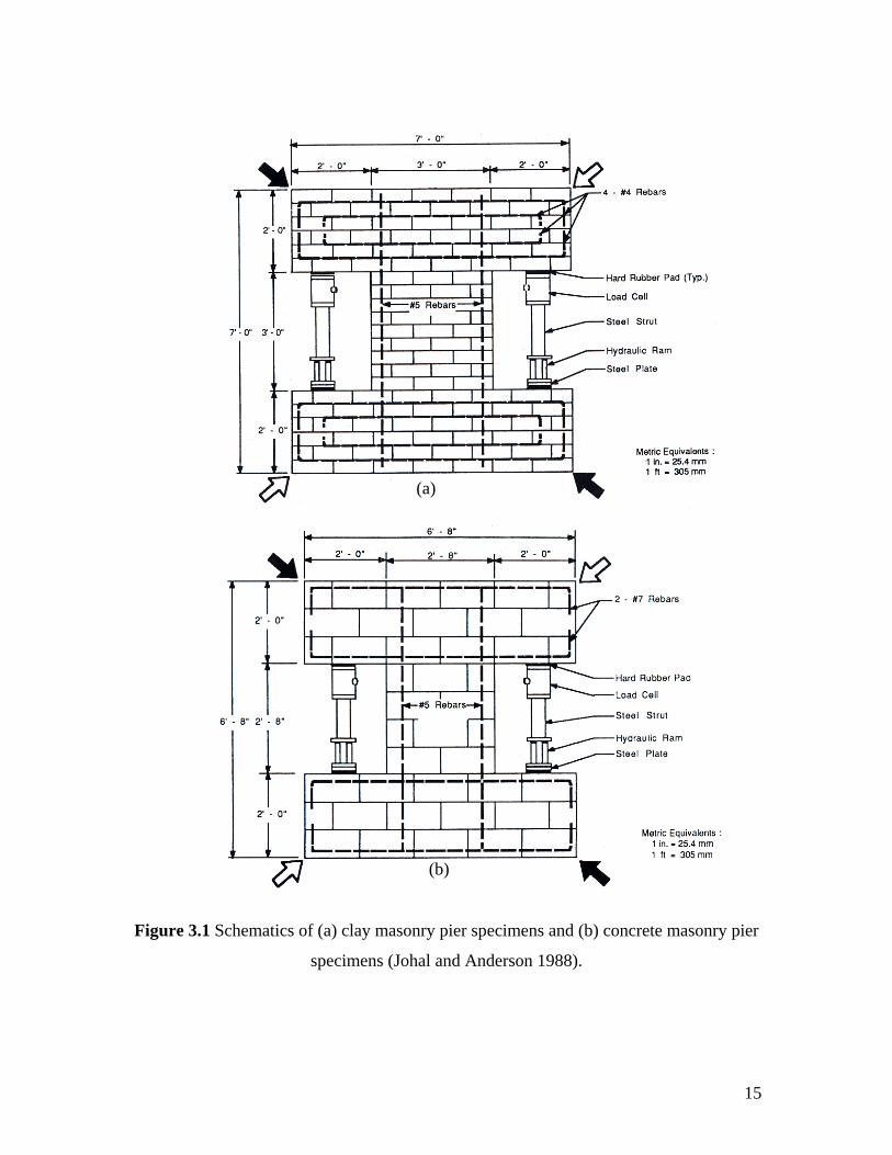
3.2 In-Plane Behavior
The only research located that specifically addressed the influence of using MC mortar
instead of PCL mortar on the in-plane response of reinforced masonry components was
reported by Johal and Anderson (1986). This study subjected 32 partially grouted
reinforced masonry piers to in-plane loads applied through diagonal compression. Both
clay (16 specimens) and concrete (16 specimens) masonry were investigated along with
various brands of masonry cement (both Type M and S). Each specimen consisted of a
square pier section (36 in. by 36 in. [914 mm by 914 mm] for clay masonry specimens
and 32 in. by 32 in. [813 mm by 813 mm] for concrete masonry specimens) and spandrel
beams along the top and bottom. All of the walls were reinforced and grouted at
approximately 24 in (610 mm) vertically and contained no horizontal reinforcement or
grout within the pier section. Figure 3.1 and 3.2 show schematics of the test specimens
and test setup, respectively.
15
Figure 3.1 Schematics of (a) clay masonry pier specimens and (b) concrete masonry pier
specimens (Johal and Anderson 1988).
(b)
(a)
16
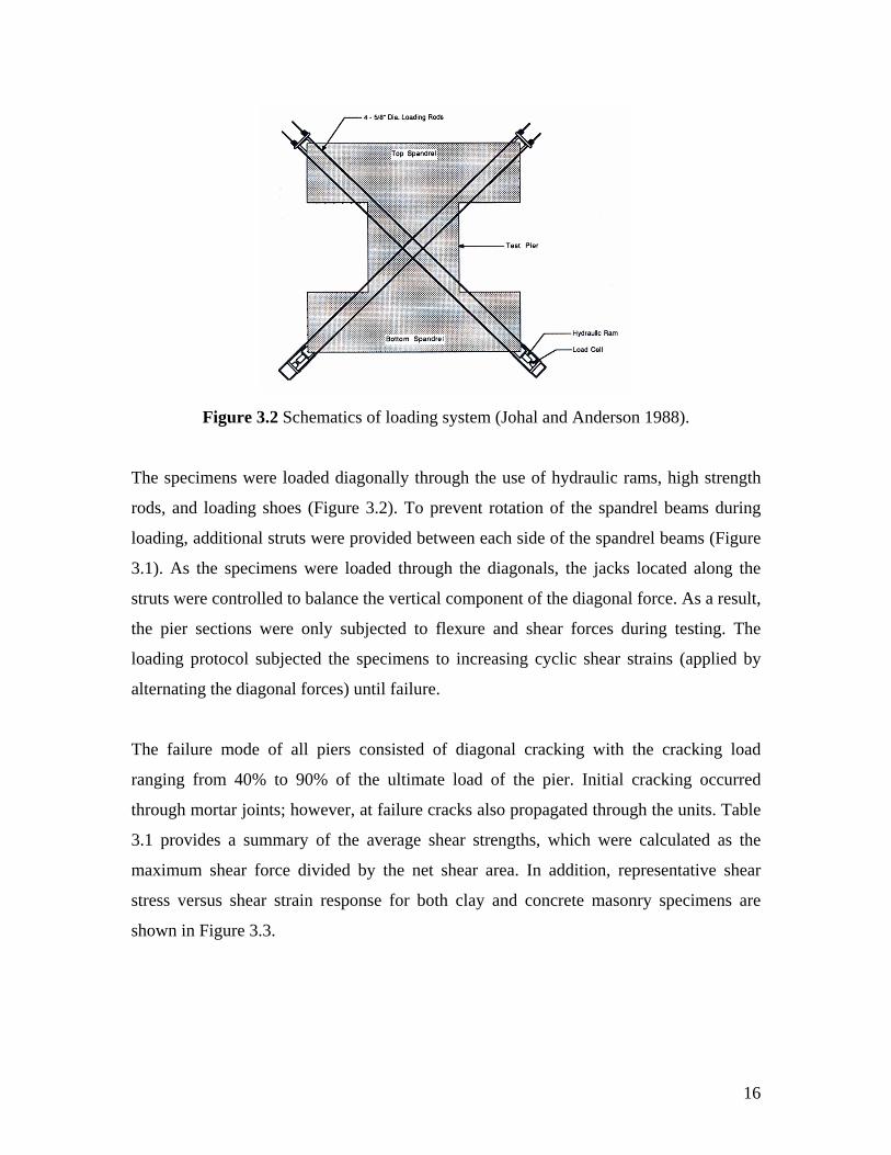
Figure 3.2 Schematics of loading system (Johal and Anderson 1988).
The specimens were loaded diagonally through the use of hydraulic rams, high strength
rods, and loading shoes (Figure 3.2). To prevent rotation of the spandrel beams during
loading, additional struts were provided between each side of the spandrel beams (Figure
3.1). As the specimens were loaded through the diagonals, the jacks located along the
struts were controlled to balance the vertical component of the diagonal force. As a result,
the pier sections were only subjected to flexure and shear forces during testing. The
loading protocol subjected the specimens to increasing cyclic shear strains (applied by
alternating the diagonal forces) until failure.
The failure mode of all piers consisted of diagonal cracking with the cracking load
ranging from 40% to 90% of the ultimate load of the pier. Initial cracking occurred
through mortar joints; however, at failure cracks also propagated through the units. Table
3.1 provides a summary of the average shear strengths, which were calculated as the
maximum shear force divided by the net shear area. In addition, representative shear
stress versus shear strain response for both clay and concrete masonry specimens are
shown in Figure 3.3.
17
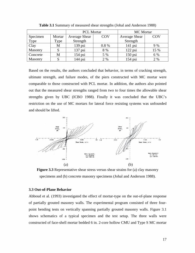
Table 3.1 Summary of measured shear strengths (Johal and Anderson 1988)
PCL Mortar MC Mortar Specimen Type
Mortar Type
Average Shear Strength
COV Average Shear Strength
COV
M 139 psi 0.8 % 141 psi 9 % Clay Masonry S 137 psi 8 % 122 psi 15 %
M 154 psi 5 % 150 psi 6 % Concrete Masonry S 144 psi 2 % 154 psi 2 %
Based on the results, the authors concluded that behavior, in terms of cracking strength,
ultimate strength, and failure modes, of the piers constructed with MC mortar were
comparable to those constructed with PCL mortar. In addition, the authors also pointed
out that the measured shear strengths ranged from two to four times the allowable shear
strengths given by UBC (ICBO 1988). Finally it was concluded that the UBC’s
restriction on the use of MC mortars for lateral force resisting systems was unfounded
and should be lifted.
Figure 3.3 Representative shear stress versus shear strains for (a) clay masonry
specimens and (b) concrete masonry specimens (Johal and Anderson 1988).
3.3 Out-of-Plane Behavior
Abboud et al. (1993) investigated the effect of mortar-type on the out-of-plane response
of partially grouted masonry walls. The experimental program consisted of three four-
point bending tests on vertically spanning partially grouted masonry walls. Figure 3.1
shows schematics of a typical specimen and the test setup. The three walls were
constructed of face-shell mortar bedded 6 in. 2-core hollow CMU and Type S MC mortar
(a) (b)
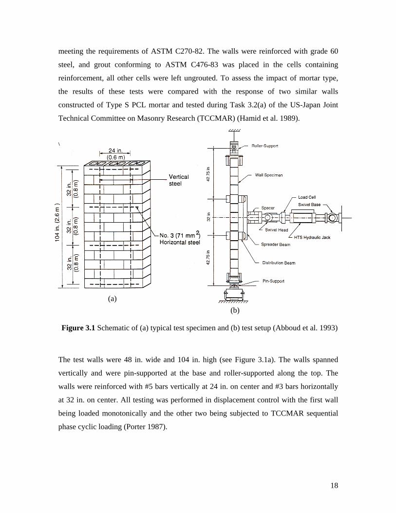
18
meeting the requirements of ASTM C270-82. The walls were reinforced with grade 60
steel, and grout conforming to ASTM C476-83 was placed in the cells containing
reinforcement, all other cells were left ungrouted. To assess the impact of mortar type,
the results of these tests were compared with the response of two similar walls
constructed of Type S PCL mortar and tested during Task 3.2(a) of the US-Japan Joint
Technical Committee on Masonry Research (TCCMAR) (Hamid et al. 1989).
\
The test walls were 48 in. wide and 104 in. high (see Figure 3.1a). The walls spanned
vertically and were pin-supported at the base and roller-supported along the top. The
walls were reinforced with #5 bars vertically at 24 in. on center and #3 bars horizontally
at 32 in. on center. All testing was performed in displacement control with the first wall
being loaded monotonically and the other two being subjected to TCCMAR sequential
phase cyclic loading (Porter 1987).
(a) (b)
Figure 3.1 Schematic of (a) typical test specimen and (b) test setup (Abboud et al. 1993)
19
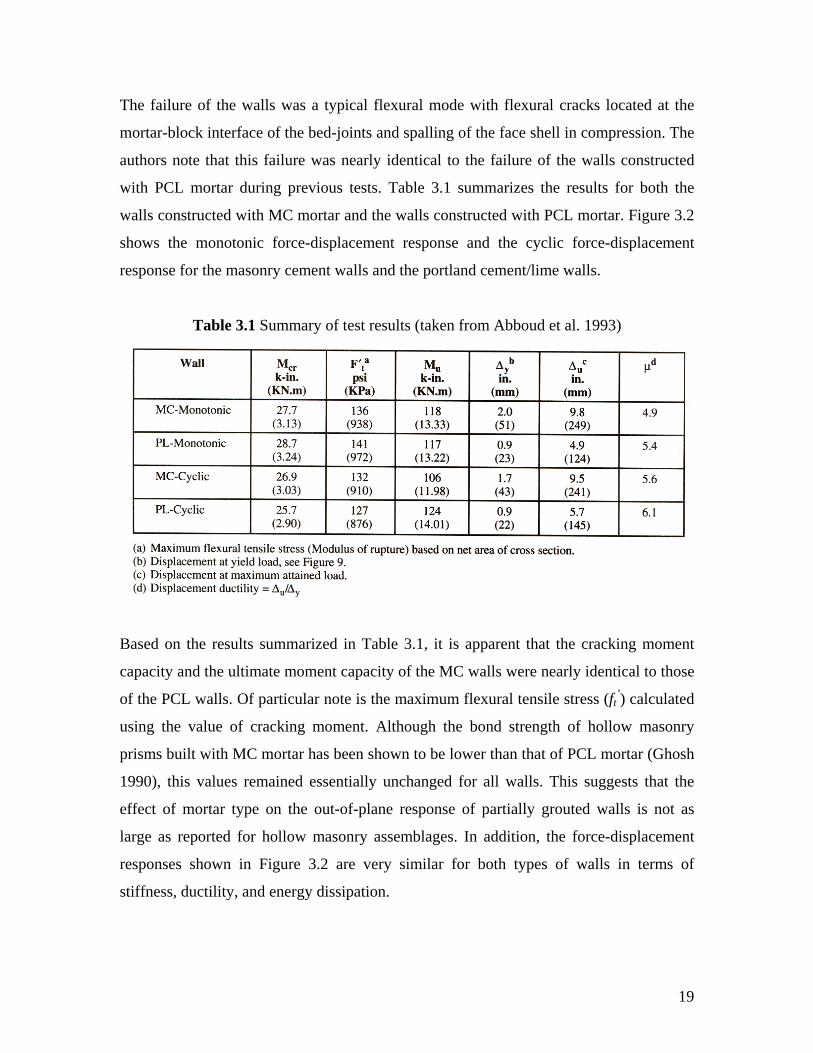
The failure of the walls was a typical flexural mode with flexural cracks located at the
mortar-block interface of the bed-joints and spalling of the face shell in compression. The
authors note that this failure was nearly identical to the failure of the walls constructed
with PCL mortar during previous tests. Table 3.1 summarizes the results for both the
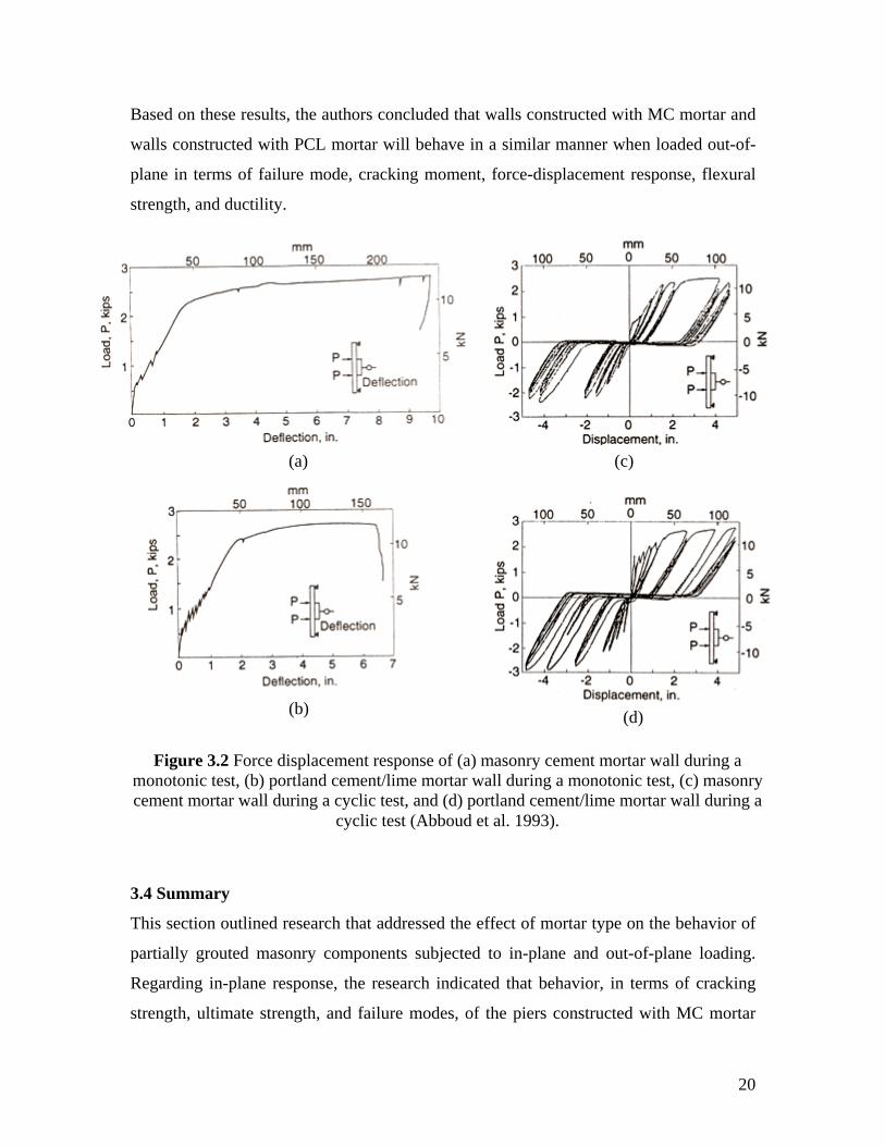
walls constructed with MC mortar and the walls constructed with PCL mortar. Figure 3.2
shows the monotonic force-displacement response and the cyclic force-displacement
response for the masonry cement walls and the portland cement/lime walls.
Table 3.1 Summary of test results (taken from Abboud et al. 1993)
Based on the results summarized in Table 3.1, it is apparent that the cracking moment
capacity and the ultimate moment capacity of the MC walls were nearly identical to those
of the PCL walls. Of particular note is the maximum flexural tensile stress (ft’) calculated
using the value of cracking moment. Although the bond strength of hollow masonry
prisms built with MC mortar has been shown to be lower than that of PCL mortar (Ghosh
1990), this values remained essentially unchanged for all walls. This suggests that the
effect of mortar type on the out-of-plane response of partially grouted walls is not as
large as reported for hollow masonry assemblages. In addition, the force-displacement
responses shown in Figure 3.2 are very similar for both types of walls in terms of
stiffness, ductility, and energy dissipation.
20
Based on these results, the authors concluded that walls constructed with MC mortar and
walls constructed with PCL mortar will behave in a similar manner when loaded out-of-
plane in terms of failure mode, cracking moment, force-displacement response, flexural
strength, and ductility.
3.4 Summary
This section outlined research that addressed the effect of mortar type on the behavior of
partially grouted masonry components subjected to in-plane and out-of-plane loading.
Regarding in-plane response, the research indicated that behavior, in terms of cracking
strength, ultimate strength, and failure modes, of the piers constructed with MC mortar
(a)
(b)
(c)
(d)
Figure 3.2 Force displacement response of (a) masonry cement mortar wall during a monotonic test, (b) portland cement/lime mortar wall during a monotonic test, (c) masonry cement mortar wall during a cyclic test, and (d) portland cement/lime mortar wall during a
cyclic test (Abboud et al. 1993).
21
were comparable to those constructed with PCL mortar. In terms of out-of-plane
response, the research suggested that the specimens constructed with MC mortar and
specimens constructed with PCL mortar behaved in a similar manner when loaded out-of-
plane in terms of failure mode, cracking moment, force-displacement response, flexural
strength, and ductility.
However, while the research results presented are consistent, they are also somewhat
limited. For example, the located studies investigated only reinforcement and grout
spacing of 24 in. As a result, it is not possible to simply extend these conclusions to cases
where the maximum reinforcement and grout spacing of 48 in. (for SDC D, E, and F
[MSJC 2005]) is used. In addition, the studies outlined employed a single test setup and
specimen configuration which does not allow these results to be generalized. For
example, the study which focused on the in-plane response of masonry piers used a single
aspect ratio and one level of vertical stress, although in-plane response of partially
grouted reinforced masonry shear walls has been shown to be sensitive to variations in
these factors (see Section 5). While this past research is extremely valuable, it is clearly
limited and, thus, a more comprehensive program is required to fully establish the impact
of MC on the response of masonry components.
22
4. EFFECT OF GROUTING ON THE PROPERTIES OF MASONRY
ASSEMBLAGES
4.1 Introduction
It is well established that grouted masonry assemblages behave considerably different
than ungrouted or hollow masonry assemblages. Since the objective of this study focuses
on partially grouted masonry, it is important to understand how the behavior mechanisms
of masonry assemblages are affected by grouting in order to gain further insight into the
possible influence of using MC mortar instead of PCL mortars for partially grouted shear
walls. The following sections discuss the effect of grouting on the behavior mechanisms
of masonry assemblages subjected to compression, bed-joint shear, diagonal tension and
flexural tension.
4.2 Compressive Strength
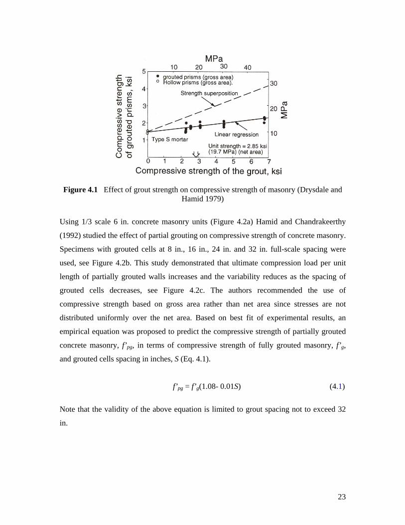
Drysdale and Hamid (1979) studied the effect of grouting on the compressive strength of
masonry prisms. The experimental results indicated that grouted masonry prisms have
failure loads lower than those predicted using superposition to combine the capacity of
the grouted area and the capacity of the unit area (Figure 4.1). This was largely attributed
to transverse tensile stresses that develop in the unit due to wedging action of the grout as
well as the lateral expansion of the grout due to the Poisson’s ratio effect. This implies
that the compression strength of grouted masonry can be expected to be less influenced
by mortar properties than that of ungrouted masonry due to the dominance of the grout
with respect to the failure mechanism. It was also noted that fully grouted specimens
typically display more uniform behavior with less scatter than ungrouted specimens.
23
Figure 4.1 Effect of grout strength on compressive strength of masonry (Drysdale and Hamid 1979)
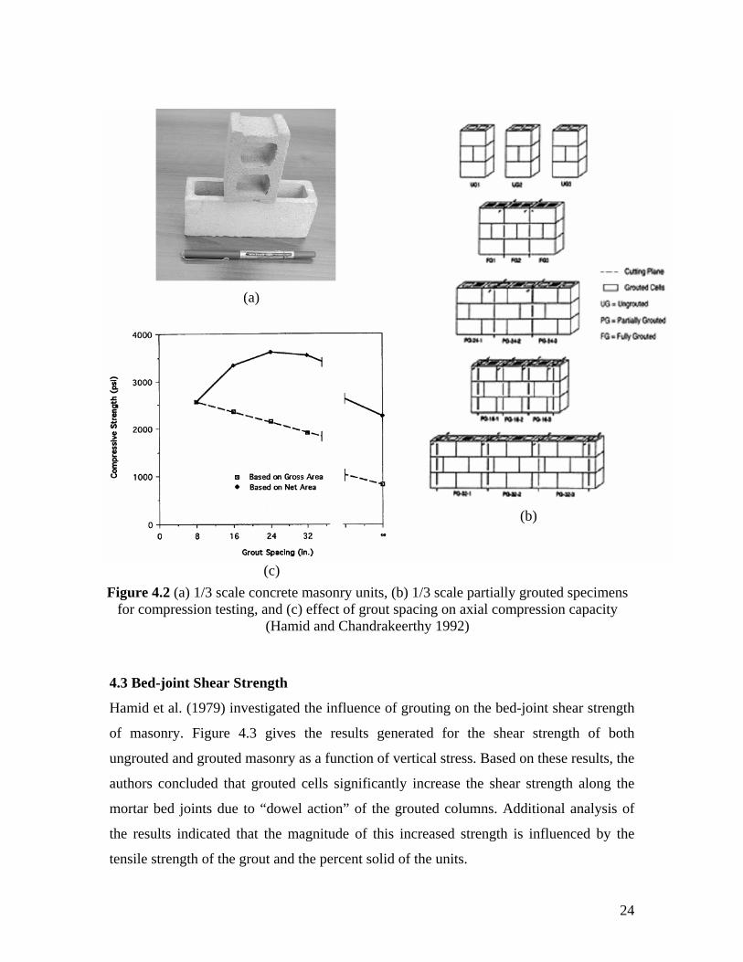
Using 1/3 scale 6 in. concrete masonry units (Figure 4.2a) Hamid and Chandrakeerthy
(1992) studied the effect of partial grouting on compressive strength of concrete masonry.
Specimens with grouted cells at 8 in., 16 in., 24 in. and 32 in. full-scale spacing were
used, see Figure 4.2b. This study demonstrated that ultimate compression load per unit
length of partially grouted walls increases and the variability reduces as the spacing of
grouted cells decreases, see Figure 4.2c. The authors recommended the use of
compressive strength based on gross area rather than net area since stresses are not
distributed uniformly over the net area. Based on best fit of experimental results, an
empirical equation was proposed to predict the compressive strength of partially grouted
concrete masonry, f’pg, in terms of compressive strength of fully grouted masonry, f’g,
and grouted cells spacing in inches, S (Eq. 4.1).
f’pg = f’g(1.08- 0.01S) (4.1)
Note that the validity of the above equation is limited to grout spacing not to exceed 32
in.
24
4.3 Bed-joint Shear Strength
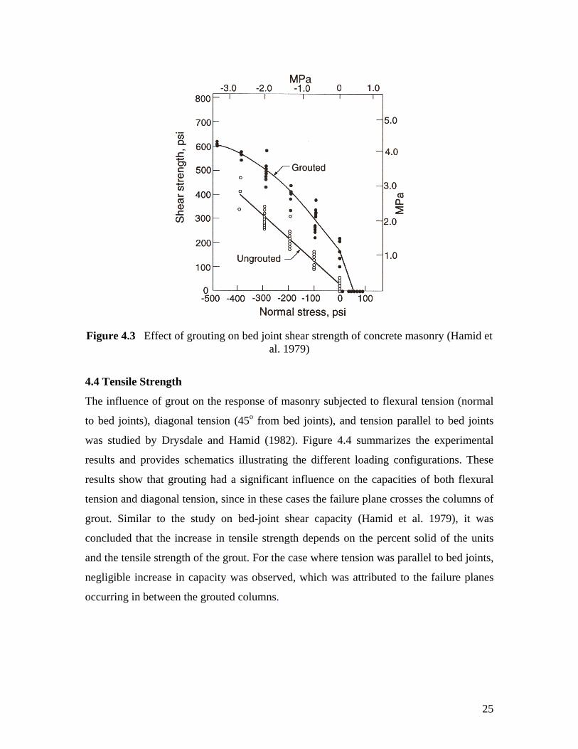
Hamid et al. (1979) investigated the influence of grouting on the bed-joint shear strength
of masonry. Figure 4.3 gives the results generated for the shear strength of both
ungrouted and grouted masonry as a function of vertical stress. Based on these results, the
authors concluded that grouted cells significantly increase the shear strength along the
mortar bed joints due to “dowel action” of the grouted columns. Additional analysis of
the results indicated that the magnitude of this increased strength is influenced by the
tensile strength of the grout and the percent solid of the units.
(b)
(a)
(c) Figure 4.2 (a) 1/3 scale concrete masonry units, (b) 1/3 scale partially grouted specimens
for compression testing, and (c) effect of grout spacing on axial compression capacity (Hamid and Chandrakeerthy 1992)
25
Figure 4.3 Effect of grouting on bed joint shear strength of concrete masonry (Hamid et
al. 1979)
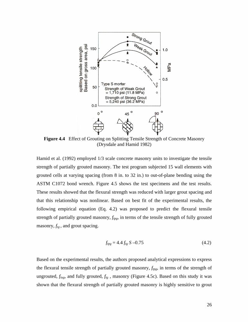
4.4 Tensile Strength
The influence of grout on the response of masonry subjected to flexural tension (normal
to bed joints), diagonal tension (45o from bed joints), and tension parallel to bed joints
was studied by Drysdale and Hamid (1982). Figure 4.4 summarizes the experimental
results and provides schematics illustrating the different loading configurations. These
results show that grouting had a significant influence on the capacities of both flexural
tension and diagonal tension, since in these cases the failure plane crosses the columns of
grout. Similar to the study on bed-joint shear capacity (Hamid et al. 1979), it was
concluded that the increase in tensile strength depends on the percent solid of the units
and the tensile strength of the grout. For the case where tension was parallel to bed joints,
negligible increase in capacity was observed, which was attributed to the failure planes
occurring in between the grouted columns.
26
Figure 4.4 Effect of Grouting on Splitting Tensile Strength of Concrete Masonry (Drysdale and Hamid 1982)
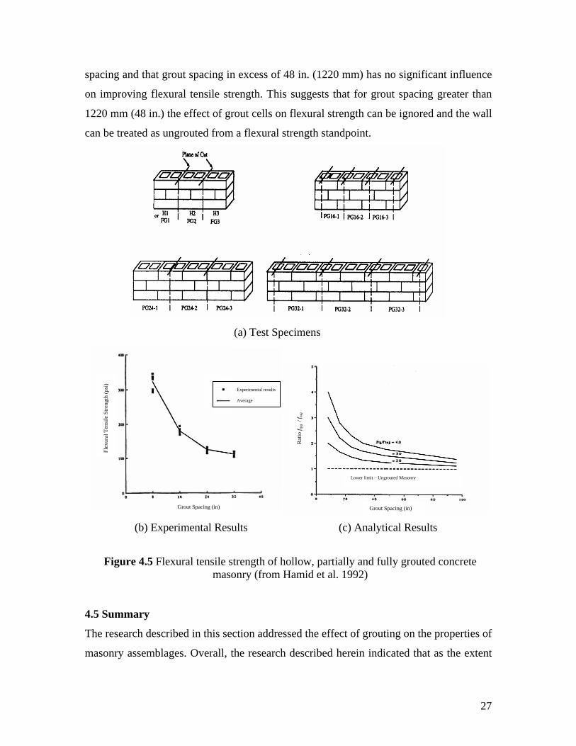
Hamid et al. (1992) employed 1/3 scale concrete masonry units to investigate the tensile
strength of partially grouted masonry. The test program subjected 15 wall elements with
grouted cells at varying spacing (from 8 in. to 32 in.) to out-of-plane bending using the
ASTM C1072 bond wrench. Figure 4.5 shows the test specimens and the test results.
These results showed that the flexural strength was reduced with larger grout spacing and
that this relationship was nonlinear. Based on best fit of the experimental results, the
following empirical equation (Eq. 4.2) was proposed to predict the flexural tensile
strength of partially grouted masonry, ftpg, in terms of the tensile strength of fully grouted
masonry, ftg , and grout spacing.
ftpg = 4.4 ftg S –0.75 (4.2)
Based on the experimental results, the authors proposed analytical expressions to express
the flexural tensile strength of partially grouted masonry, ftpg, in terms of the strength of
ungrouted, ftug, and fully grouted, ftg , masonry (Figure 4.5c). Based on this study it was
shown that the flexural strength of partially grouted masonry is highly sensitive to grout
27
spacing and that grout spacing in excess of 48 in. (1220 mm) has no significant influence
on improving flexural tensile strength. This suggests that for grout spacing greater than
1220 mm (48 in.) the effect of grout cells on flexural strength can be ignored and the wall
can be treated as ungrouted from a flexural strength standpoint.
4.5 Summary
The research described in this section addressed the effect of grouting on the properties of
masonry assemblages. Overall, the research described herein indicated that as the extent
(a) Test Specimens
Figure 4.5 Flexural tensile strength of hollow, partially and fully grouted concrete masonry (from Hamid et al. 1992)
Experimental results Average
(b) Experimental Results (c) Analytical Results
Grout Spacing (in)
Flex
ural
Ten
sile
Stre
ngth
(psi
)
Grout Spacing (in)
Rat
io f t
pg /
f tug
Lower limit – Ungrouted Masonry
28
of grouting increases, behavior becomes more uniform with a lower degree of scatter. In
terms of compression behavior, the literature established that grouted masonry prisms
have failure loads lower than those predicted using superposition due to different failure
mechanisms. In addition, past research suggested that grouted cells significantly increase
the shear strength along mortar bed joints due to “dowel action” of the grouted columns.
The tensile strength of masonry was also shown to be improved by grouting for tension
perpendicular to the bed-joints and diagonal tension. Tension parallel to the bed-joint is
not affected by grouting since the failure plane occurs between the grouted columns.
29
5. IN-PLANE BEHAVIOR OF PARTIALLY GROUTED MASONRY SHEAR
WALLS
5.1 Introduction
As mentioned in the previous section, very few studies have been identified that
addressed the effect of mortar type on the in-plane response of either partially grouted or
fully grouted reinforced masonry walls. Bridging this knowledge gap will require
additional experimental research. To develop the most efficient and effective program to
fill this need, the behavior of partially grouted masonry walls constructed of PCL mortar
must be clearly identified and understood. To that end, the following sections summarize
the available research in this area. Particular attention is paid to the behavior mechanisms
as well as key parameters that influence wall response.
5.2 Review of Past Research
Ghanem et al. (1992) investigated the effect of the distribution of vertical and horizontal
reinforcement on the in-plane response of partially reinforced masonry shears walls. The
experimental program tested three, 1/3 scale shear walls constructed of one wythe of
scaled 6 in. CMU, face-shell bedded with scaled Type S mortar joints. Scaled grout and
grade 60 #3, #4, and #5 reinforcing bars were also used in construction. The scaled walls
were approximately 3 ft by 3 ft representing a 9 ft by 9 ft prototype wall. For the three
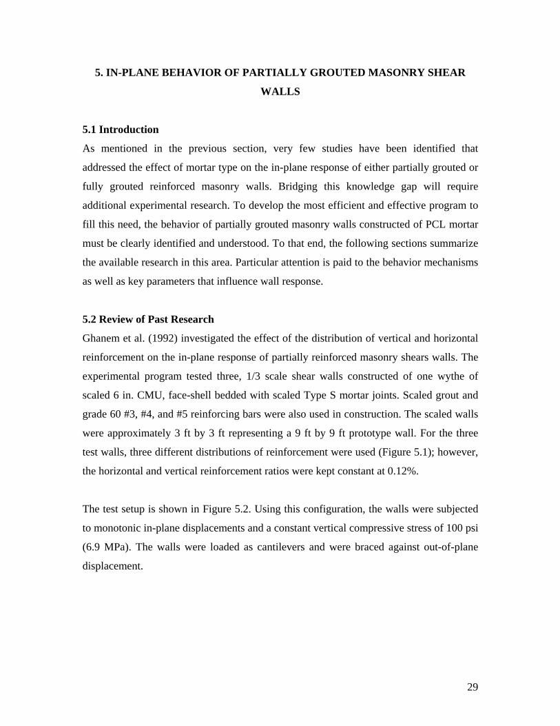
test walls, three different distributions of reinforcement were used (Figure 5.1); however,
the horizontal and vertical reinforcement ratios were kept constant at 0.12%.
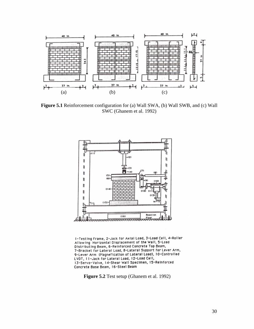
The test setup is shown in Figure 5.2. Using this configuration, the walls were subjected
to monotonic in-plane displacements and a constant vertical compressive stress of 100 psi
(6.9 MPa). The walls were loaded as cantilevers and were braced against out-of-plane
displacement.
30
Figure 5.2 Test setup (Ghanem et al. 1992)
Figure 5.1 Reinforcement configuration for (a) Wall SWA, (b) Wall SWB, and (c) Wall SWC (Ghanem et al. 1992)
(a) (b) (c)
31
The three walls tested displaced three distinctly different failure modes. Wall SWA
displayed essentially a shear failure with very little flexural deformation. Diagonal
cracking initiated at 4.8 kip of lateral load (87% of ultimate) and 0.08 in. of lateral
displacement (0.2% drift) followed by severe toe crushing at 5.5 kip of lateral load and
0.2 in. (0.5% drift) displacement. Wall SWB failed due to combined flexure/shear.
Flexural cracking was observed at a lateral load of 3 kip (50% of ultimate) and
displacement of 0.13 in. (0.3% drift). This was followed by diagonal cracking at a lateral
load of 6 kip and displacement of 0.22 in. (0.6% drift). Wall SWC failed primarily in a
flexural mode and exhibited a somewhat ductile behavior. Flexural cracking initiated at a
lateral load of 5 kip (64% of ultimate) and a displacement of 0.13 in. (0.3% drift).
Following this point the resistance of the wall continued to increase up to the peak
resistance of 7.8 kip and a displacement of 0.4 in. (1.1% drift).
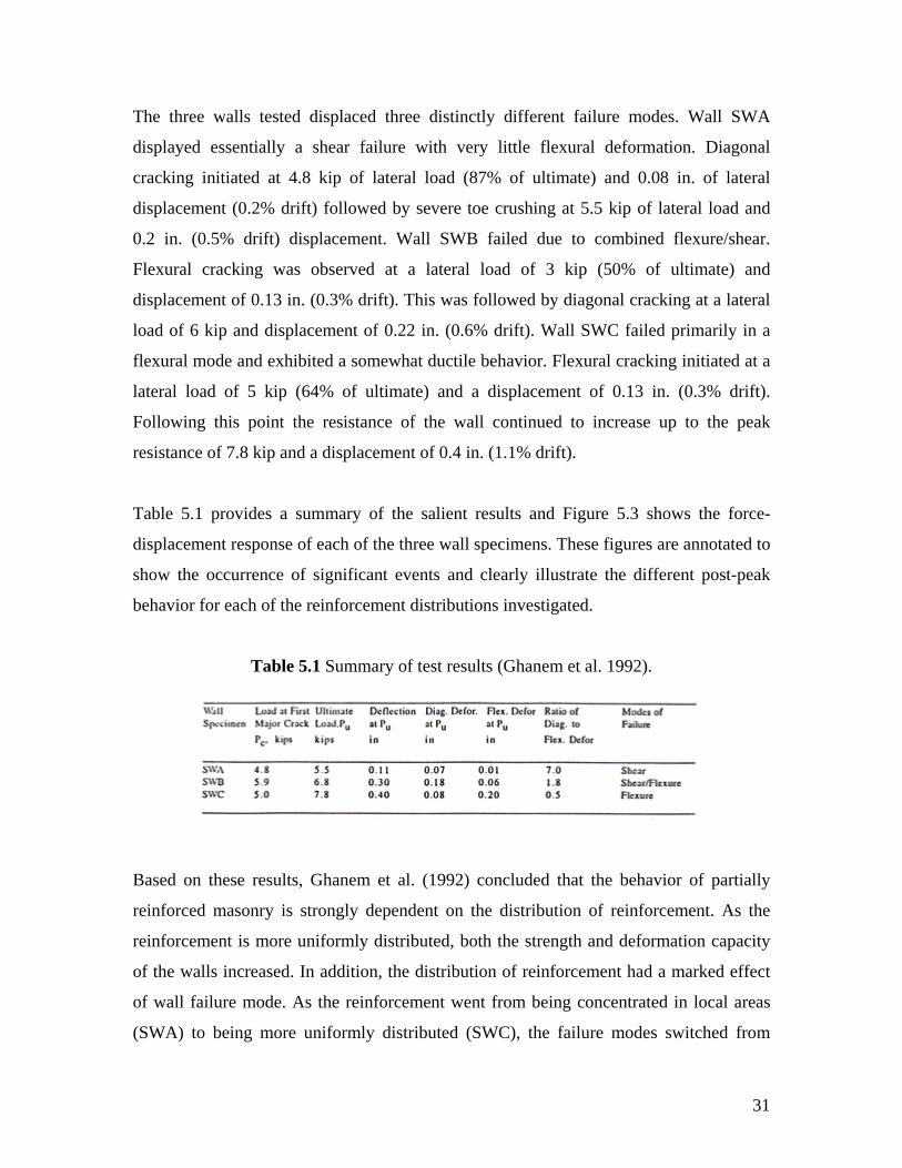
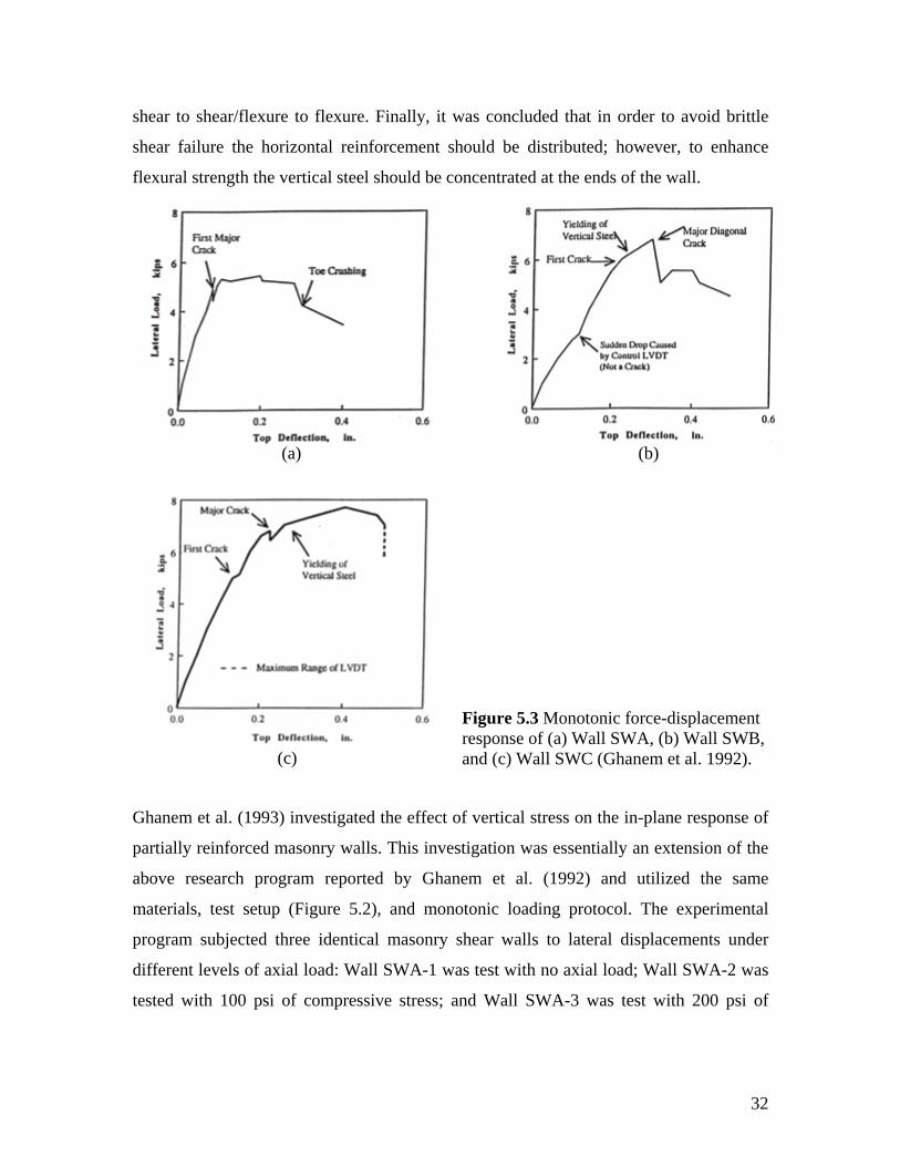
Table 5.1 provides a summary of the salient results and Figure 5.3 shows the force-
displacement response of each of the three wall specimens. These figures are annotated to
show the occurrence of significant events and clearly illustrate the different post-peak
behavior for each of the reinforcement distributions investigated.
Table 5.1 Summary of test results (Ghanem et al. 1992).
Based on these results, Ghanem et al. (1992) concluded that the behavior of partially
reinforced masonry is strongly dependent on the distribution of reinforcement. As the
reinforcement is more uniformly distributed, both the strength and deformation capacity
of the walls increased. In addition, the distribution of reinforcement had a marked effect
of wall failure mode. As the reinforcement went from being concentrated in local areas
(SWA) to being more uniformly distributed (SWC), the failure modes switched from
32
shear to shear/flexure to flexure. Finally, it was concluded that in order to avoid brittle
shear failure the horizontal reinforcement should be distributed; however, to enhance
flexural strength the vertical steel should be concentrated at the ends of the wall.
Ghanem et al. (1993) investigated the effect of vertical stress on the in-plane response of
partially reinforced masonry walls. This investigation was essentially an extension of the
above research program reported by Ghanem et al. (1992) and utilized the same
materials, test setup (Figure 5.2), and monotonic loading protocol. The experimental
program subjected three identical masonry shear walls to lateral displacements under
different levels of axial load: Wall SWA-1 was test with no axial load; Wall SWA-2 was
tested with 100 psi of compressive stress; and Wall SWA-3 was test with 200 psi of
(a) (b)
(c)
Figure 5.3 Monotonic force-displacement response of (a) Wall SWA, (b) Wall SWB, and (c) Wall SWC (Ghanem et al. 1992).
33
compressive axial stress. Each wall had vertical and horizontal reinforcement ratios of
0.12% located in the same configuration of Wall SWB shown in Figure 5.1.
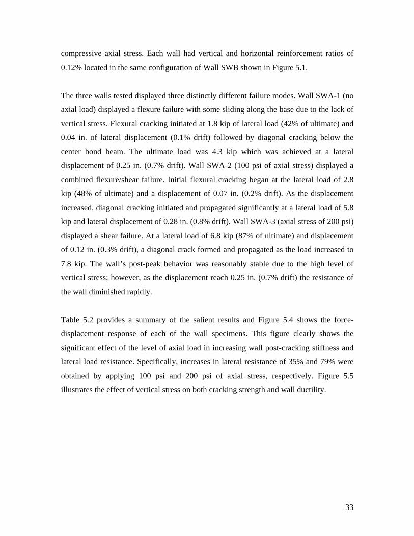
The three walls tested displayed three distinctly different failure modes. Wall SWA-1 (no
axial load) displayed a flexure failure with some sliding along the base due to the lack of
vertical stress. Flexural cracking initiated at 1.8 kip of lateral load (42% of ultimate) and
0.04 in. of lateral displacement (0.1% drift) followed by diagonal cracking below the
center bond beam. The ultimate load was 4.3 kip which was achieved at a lateral
displacement of 0.25 in. (0.7% drift). Wall SWA-2 (100 psi of axial stress) displayed a
combined flexure/shear failure. Initial flexural cracking began at the lateral load of 2.8
kip (48% of ultimate) and a displacement of 0.07 in. (0.2% drift). As the displacement
increased, diagonal cracking initiated and propagated significantly at a lateral load of 5.8
kip and lateral displacement of 0.28 in. (0.8% drift). Wall SWA-3 (axial stress of 200 psi)
displayed a shear failure. At a lateral load of 6.8 kip (87% of ultimate) and displacement
of 0.12 in. (0.3% drift), a diagonal crack formed and propagated as the load increased to
7.8 kip. The wall’s post-peak behavior was reasonably stable due to the high level of
vertical stress; however, as the displacement reach 0.25 in. (0.7% drift) the resistance of
the wall diminished rapidly.
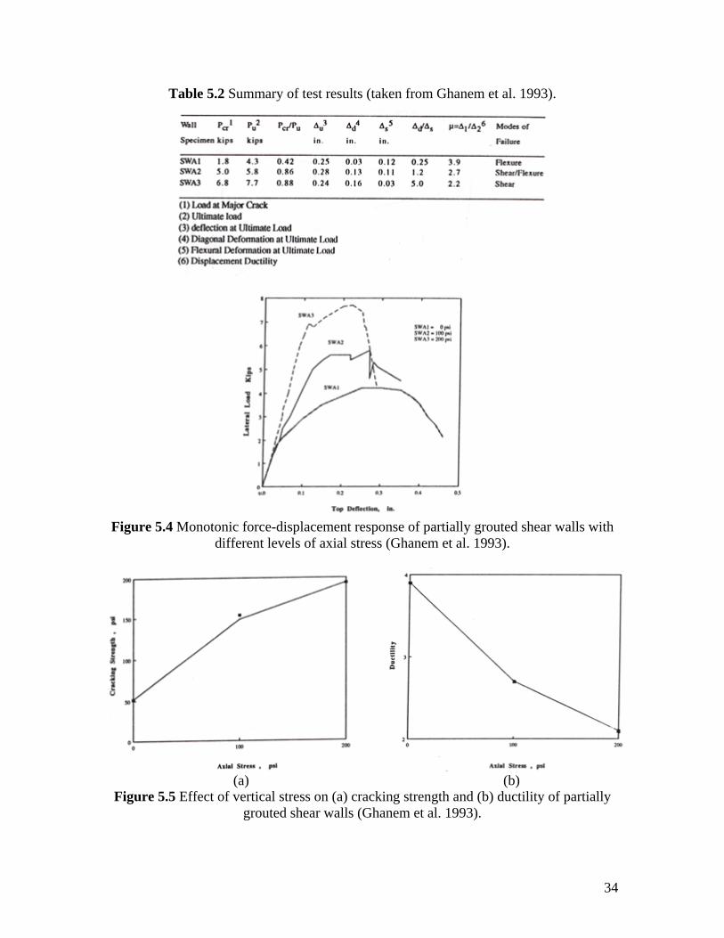
Table 5.2 provides a summary of the salient results and Figure 5.4 shows the force-
displacement response of each of the wall specimens. This figure clearly shows the
significant effect of the level of axial load in increasing wall post-cracking stiffness and
lateral load resistance. Specifically, increases in lateral resistance of 35% and 79% were
obtained by applying 100 psi and 200 psi of axial stress, respectively. Figure 5.5
illustrates the effect of vertical stress on both cracking strength and wall ductility.
34
Table 5.2 Summary of test results (taken from Ghanem et al. 1993).
Figure 5.4 Monotonic force-displacement response of partially grouted shear walls with
different levels of axial stress (Ghanem et al. 1993).
Figure 5.5 Effect of vertical stress on (a) cracking strength and (b) ductility of partially grouted shear walls (Ghanem et al. 1993).
(a) (b)
35
Based on these results Ghanem et al. (1993) concluded that the behavior of partially
reinforced masonry is strongly dependent on the level of axial stress. As the axial stress
increases, the lateral resistance of masonry shear walls increases; however, the
deformation capacity (wall displacement ductility) decreases. The level of axial stress
also has a significant influence on wall failure mode. As the axial compressive stress
went from 0 psi to 100 psi to 200 psi, the wall failure modes went from flexure to
flexure/shear to shear. Based on this trend, the authors concluded that in order to avoid
brittle failures the level of axial stress should be kept below 5% of the masonry
compressive strength.
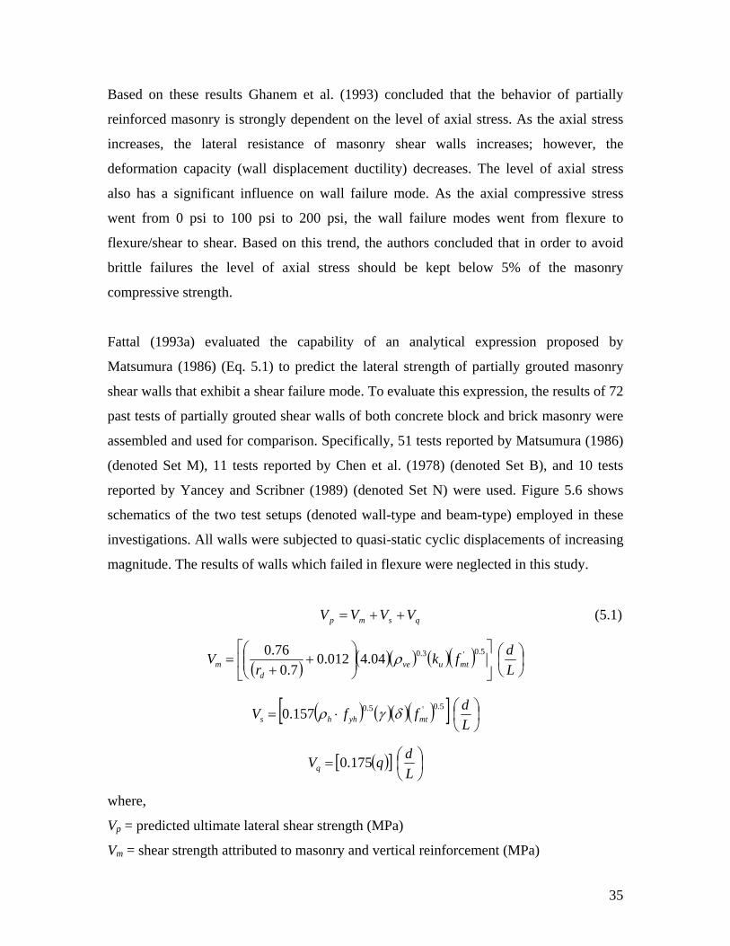
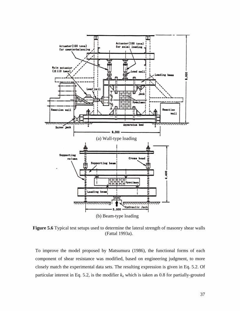
Fattal (1993a) evaluated the capability of an analytical expression proposed by
Matsumura (1986) (Eq. 5.1) to predict the lateral strength of partially grouted masonry
shear walls that exhibit a shear failure mode. To evaluate this expression, the results of 72
past tests of partially grouted shear walls of both concrete block and brick masonry were
assembled and used for comparison. Specifically, 51 tests reported by Matsumura (1986)
(denoted Set M), 11 tests reported by Chen et al. (1978) (denoted Set B), and 10 tests
reported by Yancey and Scribner (1989) (denoted Set N) were used. Figure 5.6 shows
schematics of the two test setups (denoted wall-type and beam-type) employed in these
investigations. All walls were subjected to quasi-static cyclic displacements of increasing
magnitude. The results of walls which failed in flexure were neglected in this study.
qsmp VVVV ++= (5.1)
( ) ( )( ) ( )( ) ⎟⎠⎞
⎜⎝⎛
⎥⎦
⎤⎢⎣
⎡⎟⎟⎠
⎞⎜⎜⎝
⎛+
+=
Ldfk
rV mtuve
dm
5.0'3.004.4012.07.0
76.0 ρ
( ) ( )( )( )[ ] ⎟⎠⎞
⎜⎝⎛⋅=
LdffV mtyhhs
5.0'5.0157.0 δγρ
( )[ ] ⎟⎠⎞
⎜⎝⎛=
LdqVq 175.0
where,
Vp = predicted ultimate lateral shear strength (MPa)
Vm = shear strength attributed to masonry and vertical reinforcement (MPa)
36
Vs = shear capacity attributed to horizontal reinforcement (MPa)
Vq = shear strength attributed to axial load (MPa)
rd = aspect ratio (H/d) based on effective depth, d
ρve = ratio of vertical reinforcement in one end cell
f’mt = compressive strength of masonry prisms (MPa)
d = effective depth (mm)
L = length of wall (mm)
ρh = horizontal reinforcement ratio
fyk = yield strength of horizontal reinforcement
q = nominal axial stress (MPa)
ku = 1.0 for fully-grouted concrete and brick masonry and partially grouted beam-type
brick masonry
ku = 0.8 for partially-grouted wall-type brick masonry and partially-grouted beam-type
concrete masonry
ku = 0.64 for partially-grouted wall-type concrete masonry
γ = 1.0 for fully-grouted concrete and brick masonry and partially-grouted brick
masonry
γ = 0.6 for partially grouted concrete masonry
δ = 1.0 for fixed-fixed boundary conditions
δ = 0.6 for cantilever boundary conditions
Based on data manipulation and regression analyses, Fattal highlighted several
deficiencies in Eq. 5.1. First, for walls without vertical reinforcement, Eq. 5.1 provides
poor strength estimates. This was attributed to the relative weights given to the Vm and Vs
terms. Second, Eq. 5.1 cannot accurately predict the shear strength of unreinforced
masonry walls since when Vm and Vs are zero, the lateral strength is provided exclusively
by a linear function of vertical stress. Finally, the analysis of data also pointed to
deficiencies in the functional forms of r, ρve, and ρh.
37
To improve the model proposed by Matsumura (1986), the functional forms of each
component of shear resistance was modified, based on engineering judgment, to more
closely match the experimental data sets. The resulting expression is given in Eq. 5.2. Of
particular interest in Eq. 5.2, is the modifier ko which is taken as 0.8 for partially-grouted
(a) Wall-type loading
(b) Beam-type loading
Figure 5.6 Typical test setups used to determine the lateral strength of masonry shear walls (Fattal 1993a).
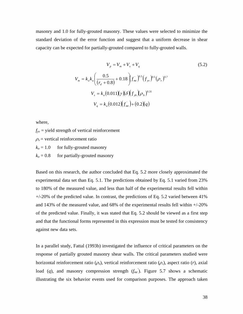
38
masonry and 1.0 for fully-grouted masonry. These values were selected to minimize the
standard deviation of the error function and suggest that a uniform decrease in shear
capacity can be expected for partially-grouted compared to fully-grouted walls.
qsmp VVVV ++= (5.2)
( ) ( ) ( ) ( ) 7.05.05.0'18.08.0
5.0vyvmt
duom ff
rkkV ρ⎟⎟
⎠
⎞⎜⎜⎝
⎛+
+=
( )( )( )( )( ) 31.0011.0 hyhos fkV ρδγ=
( )( ) ( )( )qfkV mtoq 2.0012.0 ' +=
where,
fyv = yield strength of vertical reinforcement
ρv = vertical reinforcement ratio
ko = 1.0 for fully-grouted masonry
ko = 0.8 for partially-grouted masonry
Based on this research, the author concluded that Eq. 5.2 more closely approximated the
experimental data set than Eq. 5.1. The predictions obtained by Eq. 5.1 varied from 23%
to 180% of the measured value, and less than half of the experimental results fell within
+/-20% of the predicted value. In contrast, the predictions of Eq. 5.2 varied between 41%
and 143% of the measured value, and 68% of the experimental results fell within +/-20%
of the predicted value. Finally, it was stated that Eq. 5.2 should be viewed as a first step
and that the functional forms represented in this expression must be tested for consistency
against new data sets.
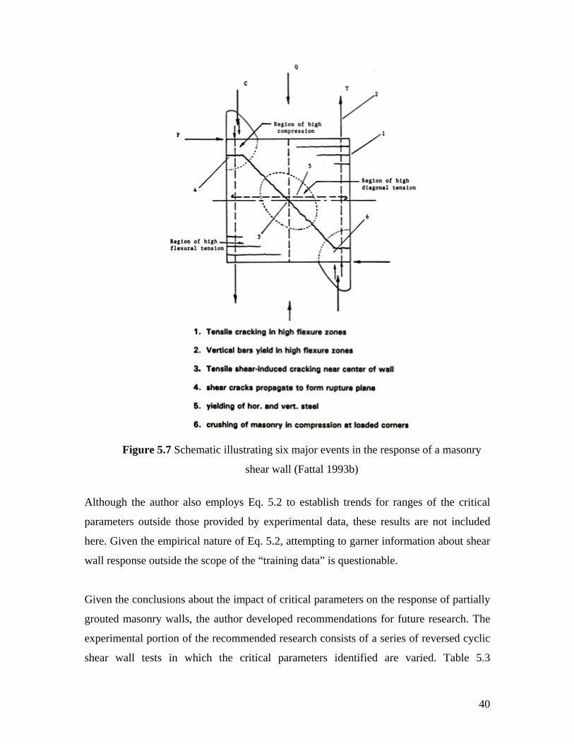
In a parallel study, Fattal (1993b) investigated the influence of critical parameters on the
response of partially grouted masonry shear walls. The critical parameters studied were
horizontal reinforcement ratio (ρh), vertical reinforcement ratio (ρv), aspect ratio (r), axial
load (q), and masonry compression strength (fmt’). Figure 5.7 shows a schematic
illustrating the six behavior events used for comparison purposes. The approach taken
39
used both the data set and strength expression (Eq. 5.2) developed by Fattal (1993a) to
establish the desired trends.
The limitations of the test data notwithstanding, the following conclusions about the
influence of the identified critical parameters were drawn:
• Within the range of 0%-0.2% horizontal reinforcement, the ultimate strength
and ultimate deformation of partially grouted masonry walls increases with an
increase in ρh. Above this level of reinforcement, ρh had little influence on
either of these properties. Although to a lesser degree, this conclusion also
applies to the cracking deformation and cracking strength.
• Above 2.0, the aspect ratio has a negligible effect on the strength of masonry
walls. As the aspect ratio is reduced, both the ultimate strength and cracking
strength of masonry walls increased. This increase was most pronounced for
aspect ratios in the range of 0.75-1.5. For the range of aspect ratios investigated
(0.75–3.0) no correlation between deformation and aspect ratio was observed.
• For the range of axial stress included in the study (0-260 psi), the lateral
strength of partially grouted masonry shear walls increased linearly within
increasing vertical stress. This trend was also reported for ungrouted,
unreinforced masonry walls; however, the author points out that partially
grouted masonry walls are approximately half as sensitive to axial stress.
40
Although the author also employs Eq. 5.2 to establish trends for ranges of the critical
parameters outside those provided by experimental data, these results are not included
here. Given the empirical nature of Eq. 5.2, attempting to garner information about shear
wall response outside the scope of the “training data” is questionable.
Given the conclusions about the impact of critical parameters on the response of partially
grouted masonry walls, the author developed recommendations for future research. The
experimental portion of the recommended research consists of a series of reversed cyclic
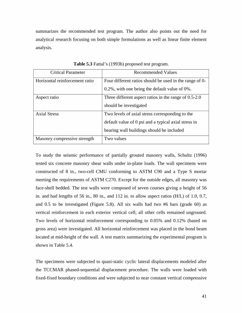
shear wall tests in which the critical parameters identified are varied. Table 5.3
Figure 5.7 Schematic illustrating six major events in the response of a masonry
shear wall (Fattal 1993b)
41
summarizes the recommended test program. The author also points out the need for
analytical research focusing on both simple formulations as well as linear finite element
analysis.
Table 5.3 Fattal’s (1993b) proposed test program.
Critical Parameter Recommended Values
Horizontal reinforcement ratio Four different ratios should be used in the range of 0-
0.2%, with one being the default value of 0%.
Aspect ratio Three different aspect ratios in the range of 0.5-2.0
should be investigated
Axial Stress Two levels of axial stress corresponding to the
default value of 0 psi and a typical axial stress in
bearing wall buildings should be included
Masonry compressive strength Two values
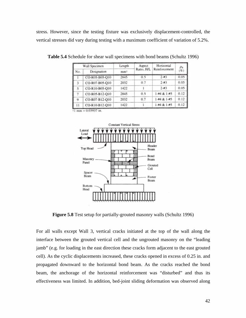
To study the seismic performance of partially grouted masonry walls, Schultz (1996)
tested six concrete masonry shear walls under in-plane loads. The wall specimens were
constructed of 8 in., two-cell CMU conforming to ASTM C90 and a Type S mortar
meeting the requirements of ASTM C270. Except for the outside edges, all masonry was
face-shell bedded. The test walls were composed of seven courses giving a height of 56
in. and had lengths of 56 in., 80 in., and 112 in. to allow aspect ratios (H/L) of 1.0, 0.7,
and 0.5 to be investigated (Figure 5.8). All six walls had two #6 bars (grade 60) as
vertical reinforcement in each exterior vertical cell; all other cells remained ungrouted.
Two levels of horizontal reinforcement corresponding to 0.05% and 0.12% (based on
gross area) were investigated. All horizontal reinforcement was placed in the bond beam
located at mid-height of the wall. A test matrix summarizing the experimental program is
shown in Table 5.4.
The specimens were subjected to quasi-static cyclic lateral displacements modeled after
the TCCMAR phased-sequential displacement procedure. The walls were loaded with
fixed-fixed boundary conditions and were subjected to near constant vertical compressive
42
stress. However, since the testing fixture was exclusively displacement-controlled, the
vertical stresses did vary during testing with a maximum coefficient of variation of 5.2%.
Table 5.4 Schedule for shear wall specimens with bond beams (Schultz 1996)
Figure 5.8 Test setup for partially-grouted masonry walls (Schultz 1996)
For all walls except Wall 3, vertical cracks initiated at the top of the wall along the
interface between the grouted vertical cell and the ungrouted masonry on the “leading
jamb” (e.g. for loading in the east direction these cracks form adjacent to the east grouted
cell). As the cyclic displacements increased, these cracks opened in excess of 0.25 in. and
propagated downward to the horizontal bond beam. As the cracks reached the bond
beam, the anchorage of the horizontal reinforcement was “disturbed” and thus its
effectiveness was limited. In addition, bed-joint sliding deformation was observed along
43
the top and bottom of the masonry panels. The failure mechanism of Wall 3 differed
considerably from the other walls and consisted of distributed cracking much like the
response of reinforced fully grouted masonry. According to the author, this discrepancy is
likely caused by differences in the actual anchorage conditions of the vertical
reinforcement bars. Whatever the cause, this anomaly clearly illustrated that the cracking
pattern exerts significant influence over the response of the wall.
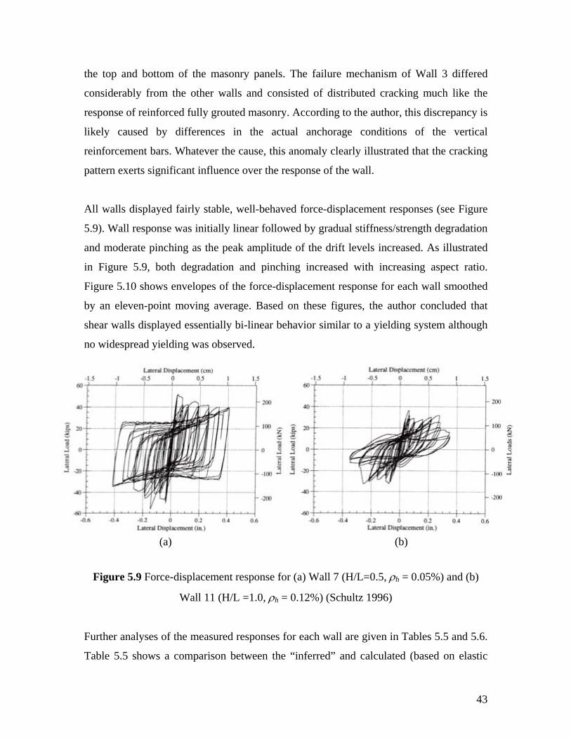
All walls displayed fairly stable, well-behaved force-displacement responses (see Figure
5.9). Wall response was initially linear followed by gradual stiffness/strength degradation
and moderate pinching as the peak amplitude of the drift levels increased. As illustrated
in Figure 5.9, both degradation and pinching increased with increasing aspect ratio.
Figure 5.10 shows envelopes of the force-displacement response for each wall smoothed
by an eleven-point moving average. Based on these figures, the author concluded that
shear walls displayed essentially bi-linear behavior similar to a yielding system although
no widespread yielding was observed.
Figure 5.9 Force-displacement response for (a) Wall 7 (H/L=0.5, ρh = 0.05%) and (b)
Wall 11 (H/L =1.0, ρh = 0.12%) (Schultz 1996)
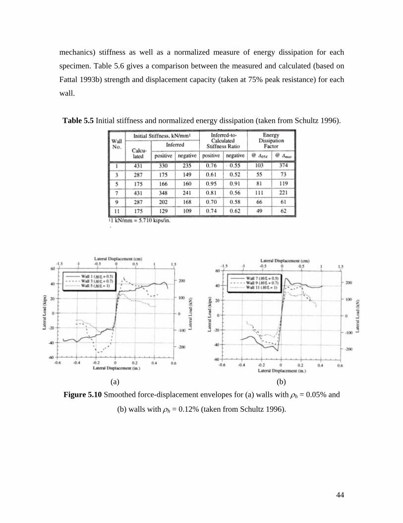
Further analyses of the measured responses for each wall are given in Tables 5.5 and 5.6.
Table 5.5 shows a comparison between the “inferred” and calculated (based on elastic
(a) (b)
44
mechanics) stiffness as well as a normalized measure of energy dissipation for each
specimen. Table 5.6 gives a comparison between the measured and calculated (based on
Fattal 1993b) strength and displacement capacity (taken at 75% peak resistance) for each
wall.
Table 5.5 Initial stiffness and normalized energy dissipation (taken from Schultz 1996).
Figure 5.10 Smoothed force-displacement envelopes for (a) walls with ρh = 0.05% and
(b) walls with ρh = 0.12% (taken from Schultz 1996).
(a) (b)
45
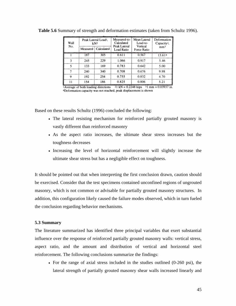
Table 5.6 Summary of strength and deformation estimates (taken from Schultz 1996).
Based on these results Schultz (1996) concluded the following:
• The lateral resisting mechanism for reinforced partially grouted masonry is
vastly different than reinforced masonry
• As the aspect ratio increases, the ultimate shear stress increases but the
toughness decreases
• Increasing the level of horizontal reinforcement will slightly increase the
ultimate shear stress but has a negligible effect on toughness.
It should be pointed out that when interpreting the first conclusion drawn, caution should
be exercised. Consider that the test specimens contained unconfined regions of ungrouted
masonry, which is not common or advisable for partially grouted masonry structures. In
addition, this configuration likely caused the failure modes observed, which in turn fueled
the conclusion regarding behavior mechanisms.
5.3 Summary
The literature summarized has identified three principal variables that exert substantial
influence over the response of reinforced partially grouted masonry walls: vertical stress,
aspect ratio, and the amount and distribution of vertical and horizontal steel
reinforcement. The following conclusions summarize the findings:
• For the range of axial stress included in the studies outlined (0-260 psi), the
lateral strength of partially grouted masonry shear walls increased linearly and
46
the displacement ductility decreased within increasing vertical stress. In
addition, the level of vertical stress had a marked effect on failure mode. As the
level of vertical stress increased wall failures were altered from flexure to
flexure/shear to shear.
• As the aspect ratio increased, the ultimate shear strength and cracking strength
of masonry walls decreased. However, above an aspect ratio 2.0, there was a
negligible effect on the strength of masonry walls. For the range of aspect ratios
investigated in the studies outlined (0.75–3.0) no correlation between
deformation and aspect ratio was observed.
• For horizontal reinforcement ratios in the range of 0%-0.2%, the ultimate
strength and ultimate deformation of partially grouted masonry walls increased
with an increase in ρh. In addition, for a constant reinforcement ratio, the
distribution of the reinforcement had a significant effect on wall failure mode
with failures progressing from shear to shear/flexure to flexure as the
reinforcement becomes more distributed.
Although none of the investigations identified examined the influence of masonry cement
mortar on the response of partially grouted masonry shear walls, none of the
investigations suggested that mortar type had any influence on wall response. Of
particular note are the studies that focused on manipulation of test data from numerous
studies. The models developed through these studies did not identify mortar properties or
mortar unit bond as factors affecting response. While this line of reasoning may not be
scientifically valid, it does at least suggest that mortar type has a negligible influence on
the response of partially grouted masonry shear walls.
47
6. CONCLUSIONS Based on the review of available literature presented in this report, the following
conclusions are drawn:
(1) The impact of mortar physical properties on compressive strength of hollow
concrete masonry is much less than that for clay brick masonry. This is
attributed to two main reasons: the low joint thickness to unit height and the
comparable unit to mortar compressive strength.
(2) For ungrouted masonry, MC mortars tend to display a lower bond strength and
a lower assemblage diagonal tension strength than the corresponding PCL
mortars. However, for fully grouted masonry, the diminished mortar bond
strength becomes negligible due to the influence of continuous grouted
columns.
(3) For masonry piers with reinforcement and grout at approximately 24 in. (610
mm) on center and aspect ratios of 1.0, negligible difference in cracking
strength, ultimate strength, and failure modes were observed between walls
constructed with MC mortars and those constructed with PCL mortars under
diagonal compression loading.
(4) For a grout and reinforcement spacing of 24 in. (610 mm), walls constructed
with MC mortar and walls constructed with PCL mortar behave in a similar
manner when loaded out-of-plane in terms of failure mode, cracking moment,
force-displacement response, flexural strength, and ductility. The conclusion
regarding cracking moment was also supported by bond wrench tests on
prisms.
48
(5) Grouting the cells of masonry units provides continuity across the weak bed
joints, reduces variability, and significantly diminishes the impact of mortar
joint properties on strength and deformation capacity of grouted masonry.
(6) The extent of grouting affects the strength of partially grouted masonry in a
nonlinear manner. That is, as the grout spacing is increased from 406 mm (16
in.) to 813 mm (32 in.) the contribution of grout does not diminish by 50%.
Based on the above findings, the authors find little evidence to support the contention that
the use of MC mortar instead of PCL mortar will have a detrimental effect on the strength
and deformation capacity of grouted and partially grouted (up to a spacing of 48 in. [1220
mm]) reinforced masonry shear walls. This conclusion is largely based on the
extrapolation of assemblage data that suggests a diminished dependence on mortar
properties when grout is introduced into the system. While this conclusion is strongly
supported by a component study of reinforced partially grouted piers, several factors
make the generalization of this study questionable including: the exclusion of influential
variables such as aspect ratio and vertical stress, the highly idealized loading condition,
and the limited grout spacing of 24 in (610 mm). (which is smaller than the maximum
allowed for structures in SDC D, E, and F). As a result, it is also recommended that a
series of shear wall tests be carried out to supplement past assemblage tests and validate
this conclusion in terms of shear wall response. To address this issue in a comprehensive
manner, the study should take into account critical parameters, in addition to mortar type,
such as wall aspect ratio, extent of grouting, level of vertical compressive stress, and the
amount and distribution of vertical and horizontal reinforcement.
49
7. REFERENCES
Abboud, B. E., A. A. Hamid, and H. G. Harris (1993) “Flexural behavior of reinforced masonry walls build with masonry cement mortar,” The Masonry Society Journal, Vol. 12 No. 1, pp.17-24. Borchelt, J.G., Melander, J.M., and Nelson, R.L. (1999) “Bond Strength and Water Penetration of High IRA Brick and Mortar,” PCA R&D Serial No. 2222. Portland Cement Association. Skokie, IL. Brown, R. and Melander, J. (1999) “ Flexural Bond Strength of Unreinforced Grouted Masonry Using PCL and MC Mortars”, in Proceedings of the Eighth North American Masonry Conference, University of Texas at Austin. Chen Shy-Wen, J., P. A. Hidalgo, R. L. Mayes, R. W. Clough, and H. D. McNiven (1978) “Cyclic loading tests of masonry single piers, Volume 2 – Height to width ratio of one,” Report No. UCB/EERC-78/28, University of California, Berkeley, CA. Drysdale R. and Hamid, A. (1979) "Behavior of Concrete Masonry Under Axial Compression," Proc. J. American Concrete Institute, Vol. 76, No. 6, pp. 702-722. Drysdale, R. and Hamid A. (1979) "Tensile Strength of Concrete Masonry," Journal of Structural Engineering, ASCE, Vol. 105, ST7, pp. 1261-1275
Drysdale, R. and Hamid, A. (1982) "In-Plane Tensile Strength of Block Masonry," Journal of the Canadian Society of Civil Engineering, Proc. Vol. 9, No. 3, pp.413-421. Drysdale, R., and Hamid, A. (1984) "Effect of Grouting on the Flexural Tensile Strength of Concrete Block Masonry," The Masonry Society J. Proc., Vol. 3, No. 2, July-Dec., pp. T10-T19. Drysdale, R.G., A.A. Hamid, and L.R. Baker (1999) “Masonry structures behavior and design,” The Masonry Society, 2nd Edition, Boulder, CO. Ghanem, G. M., A. S. Essawy, and A. A. Hamid (1992) “Effect of steel distribution on the behavior of partially reinforced masonry shear walls,” Proceedings of the 6th Canadian Masonry Symposium, University of Saskatchewan, Saskatoon, Canada. Ghanem, G. M., A. E. Salama, S. A. Elmagd, and A. A. Hamid (1993) “Effect of axial compression on the behavior of partially reinforced masonry shear walls,” Proceedings of the 6th North American Masonry Conference, Philadelphia, PA. Ghosh, S. K. (1990) “ Flexural Bond Strength of Masonry: An Experimental Review”, in Proceedings of the Fifth North American Masonry Conference, University of Illinios at Urbana-Champaign.
50
Fattal, S. G. (1993a) “Strength of partially-grouted masonry shear walls under lateral loads,” NISTIR 93-5147, National Institute of Standards and Technology, Gaithersburg, MD. Fattal, S. G. (1993b) “The effect of critical parameters on the behavior of partially-grouted masonry shear walls under lateral loads,” NISTIR 93-5147, National Institute of Standards and Technology, Gaithersburg, MD. Hamid, A., Drysdale, R., and Heidebrecht, A. (1979) "Shear Strength of Concrete Masonry Joints," Journal of Structural Engineering, ASCE, Vol. 105, ST7, pp. 1227-1240.
Hamid, A. A., B. E. Abboud, M. W. Farah, M. K. Hatem, and H. G. Harris (1989) “Response of reinforced block masonry walls to out-of-plane static loads,” US-Japan Coordinated Program for Masonry Building Research, Report No. 3.2(a), 97 pp. Hamid, A., Chaderakeerthy, S. and Elnawawy, O. (1992) "Flexural Tensile Strength of Partially Grouted Concrete Masonry", Journal of Structural Engineering, ASCE, Vol.118, No. 12, Dec.1992
Hamid, A., Chandrakeerthy, S. (1992) "Compressive Strength of Partially Grouted Concrete Masonry Using Small Scale Wall Elements," TMS Journal, Vol. 11, No.1 Hedstrom, E.G., Tarhini, K.M., Thomas, R.D., Dubovoy, V.S., Klingner, R.E., and Cook, R.A. (1991) “Flexural bond strength of concrete masonry prisms using portland cement and hydrated lime mortars,” The Masonry Society Journal, Vol. 9, No. 2, pp.8-23. International Conference of Building Officials (1988) “Uniform Building Code,” Whittier CA. International Conference of Building Officials (1991) “Uniform Building Code,” Whittier CA. Johal, L.S.P. and Anderson, E.D. (1988) “Shear strength of masonry piers under cyclic loading,” Masonry: Materials, Design, Construction, and Maintenance, ASTM STP 992. Philadelphia, PA. pp. 18-32. Masonry Standards Joint Committee (2005) “Building code requirements for masonry structures,” ACI 530/ASCE 5, TMS 402, American Concrete Institute, American Society of Civil Engineers, and The Masonry Society, Detroit, New York, Boulder. Matsumura, A. (1986) “Shear strength of reinforced hollow unit masonry walls,” Second Meeting of the U.S.-Japan Joint Technical Coordinating Committee on Masonry Research, Keystone, CO.
51
Matthys, J.H. (1992) “Brick masonry flexural bond strength using conventional masonry mortar,” Proceedings of the Fifth Canadian Masonry Symposium, University of Vancouver. Vancouver, BC. pp. 745-756. Matthys, J.H. (1989) “Brick Masonry Diagonal Tension (Shear) Tests,” Proceedings of the 5th Canadian Masonry Symposium. University of British Columbia. Vancouver, B.C., Canada. Melander, J.M, Gosh, S.K., Dubovoy, V.S., Hedstrom, E.G., and Klingner, R.E. (1993) “Flexural Bond Strength of Masonry Prisms using Masonry Cement Mortars,” Masonry: Materials, Design, Construction, and Maintenance, ASTM STP 1180. Philadelphia, PA. Porter, M.L. (1987) “Sequential phased displacement (SPD) procedure for TCCMAR testing,” Report of the Third Meeting of the US-Japan Joint Technical Committee on Masonry Research, Tomaru, Japan. Ribar, J. (1982) “Water Permeance of Masonry: A Laboratory Study” Masonry: Materials, Properties and Performance, ASTM STP 778, Philadelphia, PA Schultz, A. E. (1996) “Seismic resistance of partially-grouted masonry shear walls,” Proceedings of the 1996 CCMS of the ASCE Symposium in Conjunction with Structures Congress XIV, Chicago, IL. Speweik, J. P. (1995) “The history of Masonry Mortar in America” in Proceedings of the Seventh Canadian Masonry Symposium, McMaster University, Hamilton, Canada. Yancey C. W. C. and C. F. Scribner (1989) “Influence of horizontal reinforcement on the shear resistance of concrete block masonry walls,” NISTIR 89-4202, National Institute of Standards and Technology, Gaithersburg, MD.