rekeying manual - mmt o - tom's home...
TRANSCRIPT

R e k e y i n g M a n u a lFor use with Keying Kits 40-132 & 40-134
®
2
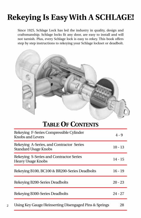
TABLE OF CONTENTSRekeying F-Series Compressible Cylinder Knobs and Levers 4 - 9
Rekeying A-Series, and Contractor SeriesStandard Usage Knobs 10 - 13
Rekeying S-Series and Contractor SeriesHeavy Usage Knobs 14 - 15
Rekeying B100, BC100 & BR200-Series Deadbolts 16 - 19
Rekeying B200-Series Deadbolts 20 - 23
Rekeying B300-Series Deadbolts 24 - 27
Using Key Gauge/Reinserting Disengaged Pins & Springs 28
Since 1925, Schlage Lock has led the industry in quality, design andcraftsmanship. Schlage locks fit any door, are easy to install and will not tarnish. Plus, every Schlage lock is easy to rekey. This book offersstep by step instructions to rekeying your Schlage lockset or deadbolt.
Rekeying Is Easy With A SCHLAGE!

Keying Kit 40-132 Includes everything you need to rekey the most popularSchlage knobs, levers and B-Series deadbolts. Includes bottom pins, toppins, springs, cylinder caps, cap pins, cap pin springs, B-Series deadbolttailpieces, key gauge, plug follower and cap removal tool.
Keying Kit 40-134 Contains all of the basic materials to rekey most Schlageknobs and levers. Includes bottom pins, top pins, springs, cylinder caps, cappins, key gauge and plug follower.
3
SCHLAGE Keying Kits Provide Everything You Need To Get The Job Done!

STEP #1 - LOCK DIS-ASSEMBLY
Insert key into cylinder plug, rotate90°.
Depress knob catch using tab on keygauge and pull knob off of knobcatch.
Use your thumb and forefinger toapply pressure on the rose and pullknob/lever off spindle.
To remove the cylinder, first ensure that the keyway on the plug is facing upright. Next,allow the tail end of the cylinder to drop down slightly so that the top of the face of thecylinder sits in at an angle. The cylinder should not fall completely into the body of theknob (like picture E, not like picture F).
A B
C
Rotate key back 90° to originalposition and remove key.
D
E F
4
YES NO
F-Series Compressible

STEP #2 - CYLINDER REMOVAL
Carefully push the cylinder out of the back of the knob by applyingpressure to the top of the cylinderplug face.
The cylinder will automatically compress and exit the rear of theknob through the shank of the knob.
G H
5
Caution: To remove the cylinder through the rear of the knob, you will not need to use more than 5 pounds of force (or the amount offorce required to push an elevator button). If you require more force,the cylinder is not aligned correctly for removal. Please refer to stepsE and F for correct alignment.
Cylinder Knobs and Levers

STEP #3 - CYLINDER REPINNING - METHOD 1
Keep the plug follower in the body to keep the top pins and springs from blowing.Dump the bottom pins from the plug. Insert & rotate the key 90° and insert the end ofthe plug follower into the rear of the cylinder housing - pushing the plug out the frontof the housing.
B C
Using U-Shaped portion of key gauge,press forward to remove C-Clip cylinderretaining ring
A
Schlage’s compressible cylinders can be rekeyed using one of two methods:
Method 1: (recommended) The new compressible cylinders can be rekeyed inthe exact same manner the F-Series cylinders have been rekeyed for decades.To rekey, simply remove the C-Clip from the back of the plug and use the plugfollower to remove the plug from the body. The plug follower is also used tohold the top pins and springs in the body. The bottom pins in the plug can thenbe replaced - and the plug reinserted into the body. Finally, reattach the C-Clip onto the back of the plug.
F-Series Compressible
6

STEP #3 - CYLINDER REPINNING - METHOD 2
STEP #3 - CYLINDER REPINNING - METHOD 1
Using a screwdriver or other smalledge carefully pry off the steel capfrom the top of the cylinder
A
Dump contents from the top of thecylinder (springs, top pins and bottom pins)
B
Load new bottom pins into the plugthat correspond to the new key com-bination
Re-insert the plug back into the hous-ing and push the plug follower backout. Finally, re-insert the C-Clipcylinder retaining ring onto the backof the plug
D E
Method 2: The new compressible cylinders can be rekeyed from the top ofthe cylinder by removing the stainless steel cap – and dumping the bottompins, top T-Pins, and top springs from the cylinder. To rekey, simply insertnew bottom pins into the holes on the top of the cylinder and then re-insertthe top T-pins and springs on top of the bottom pins. Finally, attach a NEWstainless steel cap to the top of the cylinder body by aligning the holes in thetop cap with the holes in the springs. Each spring should encircle each holeon the cap.
Cylinder Knobs and Levers
7

F-Series Compressible
STEP #3 - CYLINDER REPINNING - METHOD 2
8
Attach a NEW steel cap onto the topof the housing - aligning each springwith the hole in the cap. The teeth ofthe cap should also align with thegrooves on the housing
D
Align the holes in the plug with the holes in the housing. Load new bottom pins andre-load the top T-Pins (see inset for correct insertion direction). Re-load the springsover the top of the thin part of the top T-Pins.
C TOP
BOTTOM

Cylinder Knobs and Levers
Compress the cap and re-insert the cylinder into the shank of the knob (plug face first)aligning the cap with the slot in the sleeve inside the knob. With the cap aligned withthe slot, push the cylinder the rest of the way into the knob
STEP #4 - LOCK REASSEMBLY
Insert key into cylinder plug, rotate90°. Line up slot on the shank of theknob with catch on spindle and slideknob onto spindle
If necessary, depress knob catch andslide knob on until the catch popsinto the slot on knob. Rotate key 90°and remove key
A B
C D
9

STEP #1 - REMOVE THE KNOB
Put key into cylinder (with teeth of keyfacing up) and turn key clockwise onequarter turn to three o’clock position.
Using tab on key gauge, depress knobretainer through hole in knob shank.
Use thumb and forefinger to applypressure on rose and pull knob offspindle.
Push cylinder forward until knobsleeve disengages from back of knob.Remove sleeve and set it aside.
Remove key from cylinder and removecylinder from back of knob.
STEP #2 - REMOVE THE CYLINDER
A B
C
A B
A-Series and Contractor
10
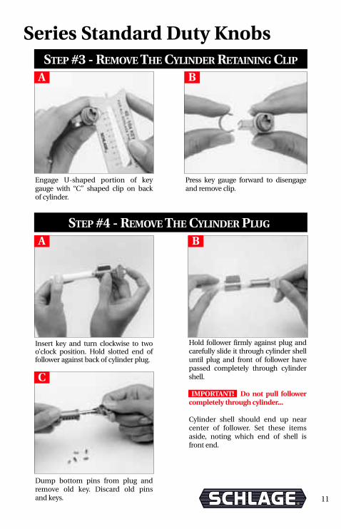
Engage U-shaped portion of key gauge with “C” shaped clip on back of cylinder.
Press key gauge forward to disengageand remove clip.
STEP #3 - REMOVE THE CYLINDER RETAINING CLIP
STEP #4 - REMOVE THE CYLINDER PLUG
Insert key and turn clockwise to twoo’clock position. Hold slotted end offollower against back of cylinder plug.
Hold follower firmly against plug andcarefully slide it through cylinder shelluntil plug and front of follower havepassed completely through cylindershell.
IMPORTANT! Do not pull follower completely through cylinder...
Cylinder shell should end up near center of follower. Set these itemsaside, noting which end of shell is front end.
Dump bottom pins from plug andremove old key. Discard old pins and keys.
A B
A B
C
Series Standard Duty Knobs
11
A-Series and Contractor STEP #5 - LOAD NEW BOTTOM PINS
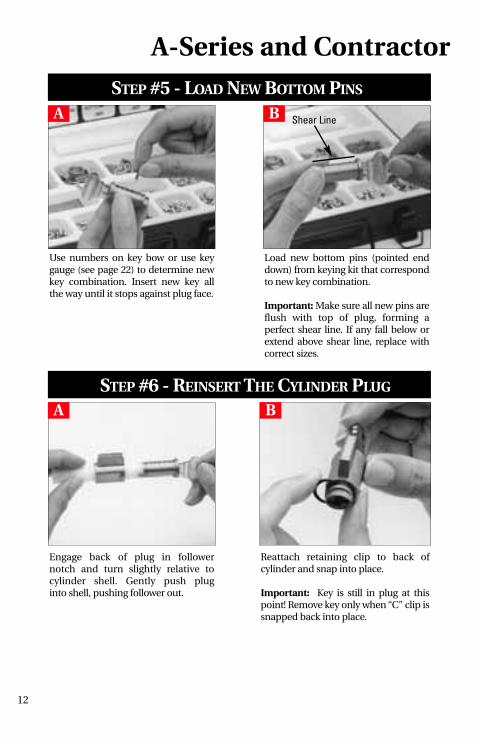
Use numbers on key bow or use keygauge (see page 22) to determine newkey combination. Insert new key all the way until it stops against plug face.
Load new bottom pins (pointed enddown) from keying kit that correspondto new key combination.
Important: Make sure all new pins areflush with top of plug, forming a perfect shear line. If any fall below orextend above shear line, replace withcorrect sizes.
Engage back of plug in follower notch and turn slightly relative to cylinder shell. Gently push pluginto shell, pushing follower out.
Reattach retaining clip to back of cylinder and snap into place.
Important: Key is still in plug at thispoint! Remove key only when “C” clip issnapped back into place.
STEP #6 - REINSERT THE CYLINDER PLUG
A B
A B
Shear Line
12
Series Standard Duty Knobs
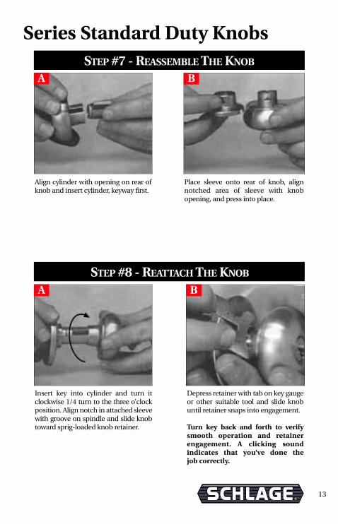
Align cylinder with opening on rear ofknob and insert cylinder, keyway first.
Place sleeve onto rear of knob, alignnotched area of sleeve with knob opening, and press into place.
STEP #7 - REASSEMBLE THE KNOB
STEP #8 - REATTACH THE KNOB
Insert key into cylinder and turn itclockwise 1/4 turn to the three o’clock position. Align notch in attached sleevewith groove on spindle and slide knobtoward sprig-loaded knob retainer.
Depress retainer with tab on key gaugeor other suitable tool and slide knobuntil retainer snaps into engagement.
Turn key back and forth to verifysmooth operation and retainerengagement. A clicking sound indicates that you’ve done the job correctly.
A B
A B
13
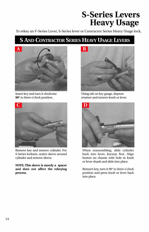
S-Series Levers Heavy Usage
To rekey an F-Series Lever, S-Series lever or Contractor Series Heavy Usage lock,
Insert key and turn it clockwise 90° to three o’clock position.
Using tab on key gauge, depress retainer and remove knob or lever.
S AND CONTRACTOR SERIES HEAVY USAGE LEVERS
Remove key and remove cylinder. ForS-Series locksets, notice sleeve aroundcylinder and remove sleeve.
NOTE: This sleeve is merely a spacerand does not affect the rekeyingprocess.
When reassembling, slide cylinderback into lever, keyway first. Align button on chassis with hole in knob or lever shank and slide into place.
Reinsert key, turn it 90° to three o’clock position and press knob or lever backinto place.
A B
C D
14
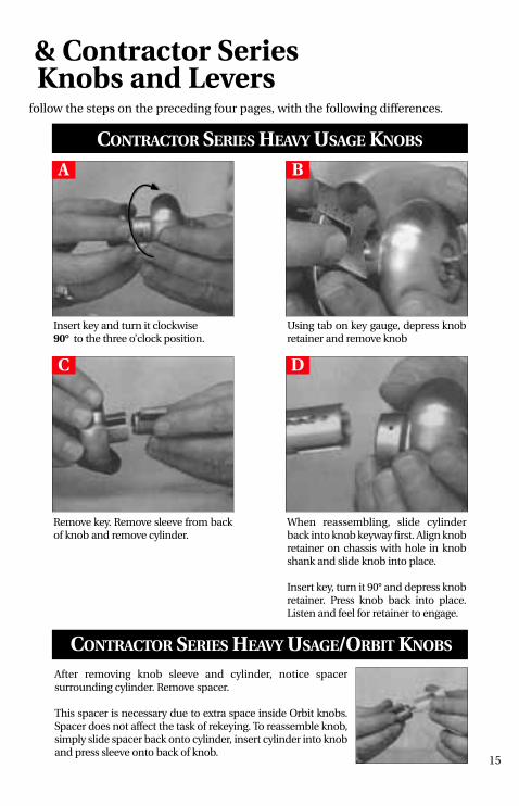
& Contractor Series Knobs and Levers
CONTRACTOR SERIES HEAVY USAGE KNOBS
Insert key and turn it clockwise90° to the three o’clock position.
Using tab on key gauge, depress knobretainer and remove knob
Remove key. Remove sleeve from backof knob and remove cylinder.
When reassembling, slide cylinderback into knob keyway first. Align knobretainer on chassis with hole in knobshank and slide knob into place.
Insert key, turn it 90° and depress knobretainer. Press knob back into place.Listen and feel for retainer to engage.
After removing knob sleeve and cylinder, notice spacer surrounding cylinder. Remove spacer.
This spacer is necessary due to extra space inside Orbit knobs.Spacer does not affect the task of rekeying. To reassemble knob,simply slide spacer back onto cylinder, insert cylinder into knoband press sleeve onto back of knob.
CONTRACTOR SERIES HEAVY USAGE/ORBIT KNOBS
A B
C D
follow the steps on the preceding four pages, with the following differences.
15

Schlage B100/BC100/ STEP #1 - PREPARATION
Remove cylinder assembly from its collar. Place cylinder face down on asmooth surface.
Align scallops of cylinder cap withteeth on cylinder cap removal tool.Push tool down against slight springpressure. Unscrew cap and remove it.
Remove cap, washer, pin and springfrom back of cylinder plug and set aside.
STEP #2 - REMOVE THE CYLINDER CAP
A
A B
16
NOTE: If cap removal tool is lost, use tab on key gage or other small tool to depress cappin and unscrew cap with fingers.
The photographs in this section depict B100 housings; however, the BC100 and BR200Series cylinders rekey the same way.
Remove the attached tailpiece from theback of the cylinder and place the housingface down on a smooth surface.
B100/BC100 BR200A
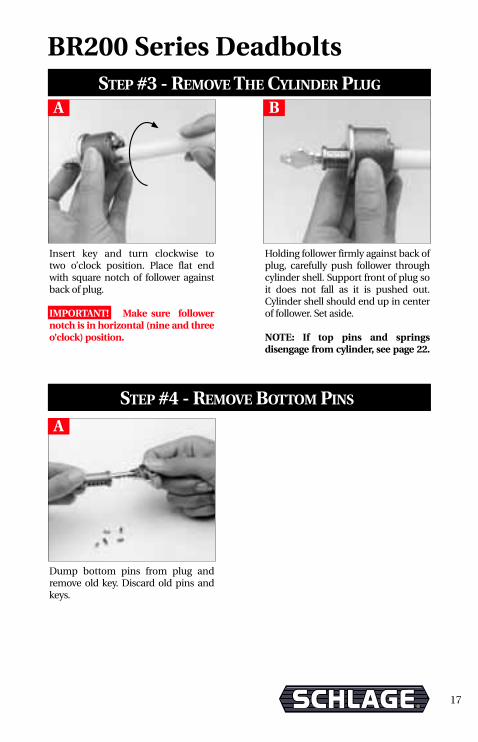
STEP #3 - REMOVE THE CYLINDER PLUG
Insert key and turn clockwise to two o’clock position. Place flat end with square notch of follower againstback of plug.
IMPORTANT! Make sure followernotch is in horizontal (nine and threeo’clock) position.
Holding follower firmly against back ofplug, carefully push follower throughcylinder shell. Support front of plug soit does not fall as it is pushed out.Cylinder shell should end up in centerof follower. Set aside.
NOTE: If top pins and springs disengage from cylinder, see page 22.
A B
STEP #4 - REMOVE BOTTOM PINS
Dump bottom pins from plug andremove old key. Discard old pins andkeys.
A
17
BR200 Series Deadbolts

Again, place flat end of follower againstback of plug. Carefully push plug intoshell, pushing follower out.
Insert key and place thumb againstplug face. CAREFULLY pull key out,leaving plug locked in shell.
STEP #6 - REINSERTING CYLINDER PLUG
A B
STEP #5 - LOAD NEW BOTTOM PINS
Use numbers on key bow or use keygauge (see page 22) to determine new key combination. Insert new key all the way until it stops againstplug face.
A B
Load new bottom pins (pointed enddown) into plug with pins from keying kit corresponding to new keycombination.
IMPORTANT! All pins must be flushwith top of plug, forming a perfectshear line. If any fall below or extendabove shear line, replace with correctsizes.
Shear Line
18
Schlage B100/BC100/

STEP #7 - CYLINDER CAP REASSEMBLY
Place cylinder face down on a smoothsurface. Insert cap pin spring and cappin into small hole in back of plug.
Place washer on back of plug raisedside up with notch around cap pin.
A B
Screw cylinder cap back on with capremoval tool until cap is all the way onbut not tight.
Test cylinder by inserting key, turningboth directions, and removing it. If keyturns hard or not at all, cap may be tootight. If key won’t come out withoutpressing against plug face, cap is tooloose. Adjust cap accordingly.
C
19
BR200 Series Deadbolts

STEP #1 - PREPARATION
Remove cylinder assembly from rearof collar assembly.
To remove “C-Shaped” retainer, aligntailpiece with half-round notch inkey gauge (40-104) as shown. Pushkey gauge against C-clip until it popsoff. Remove tailpiece.
STEP #2 - REMOVE PLUG RETAINER
A B
A B
Remove phillips head screw andremove cylinder from its housing.
20
Schlage B200 Series Deadbolts

STEP #3 - REMOVE THE CYLINDER PLUG
Insert key and turn clockwise to two o’clock position. Do not removethis plug.
A
C
STEP #4 - REMOVE BOTTOM PINS
Dump bottom pins from plug andremove old key. Discard old pins andkeys.
A
To remove plug, use notched end offollower (as shown).
B
D
Caution: To avoid top pins springingout, push follower all the way throughin one continuous careful motion.When completed, shell should be nearcenter of follower.
Align notched end of follower withcylinder plug.
NOTE: If top pins and springs disengage from cylinder, see page 22.
21
Schlage B200 Series Deadbolts

Place notched end of followeragainst back of plug. Hold plugturned to the two o’clock positionwith the key inserted.
Carefully push plug into shell, pushing follower out into other hand. DO NOT REMOVE KEY!
STEP #6 - REINSERTING CYLINDER PLUG
A B
STEP #5 - LOAD NEW BOTTOM PINS
Use numbers on key bow or use keygauge (see page 22) to determinenew key combination. Insert new keyall the way until it stops against plugface.
A B
Load new bottom pins into plug withpins from keying kit to correspond withnew key combination. Begin with pinchamber closest to key bow.
IMPORTANT! Make sure all pins areflush with top of plug, forming a per-fect shear line. If any fall below orextend above shear line, replace withcorrect sizes.
Shear Line
Schlage B200 Series Deadbolts
22

Secure cylinder in place with Phillipsscrew.
STEP #7 - CYLINDER CAP REASSEMBLY
Reinstall C-shaped plug retainer andtailpiece. Remove key.
Be sure retainer does not block keyslot on bottom of plug.
A B
Place cylinder into its housing.
C
23
Schlage B200 Series Deadbolts

Schlage B300 Maximum STEP #1 - PREPARATION
Remove adapter ring (For 11/2˝openingonly). Place cylinder assembly facedown on smooth surface.
Lift crank assembly and retainer overbumps with flat blade screwdriver andremove.
Remove black retainer and crank.
Engage teeth of cylinder cap removaltool with scallops in cylinder cap asshown. Push tool down against slightspring pressure and unscrew cap.
Remove cap, tailpiece, washer, cap pinand spring from back of plug and setaside.
NOTE: To remove tiny cap pin spring,turn cylinder assembly upside downand gently tap on table.
STEP #2 - REMOVE THE CYLINDER CAP
A B
C
A B
24
Crank
Retainer

Security Deadbolt Series STEP #3 - REMOVE CYLINDER PLUG
Insert key and turn clockwise to twoo’clock position. Place flat end of follower against back of cylinder plug.
Caution: To avoid top pins springingout of cylinder shell, push follower all the way through in one careful, continuous motion. When completed,shell should be near center of follower.
NOTE: If the top pins and springs disengage, please see page 22.
A B
STEP #4 - LOAD NEW BOTTOM PINS
Use numbers on key bow or use key gauge (see page 22) to determinenew key combination. Insert new key all the way until it stops againstplug face.
A B
Load new bottom pins (pointed enddown) into plug with pins from kit cor-responding to new key combination.
IMPORTANT! Make sure that all pinsare flush with top of plug, forming aperfect shear line. If any extend aboveor below the surface, replace with cor-rect sizes.
25
Dump bottom pins from plug andremove old key. Discard old pins andkeys.
C
Shear Line

Schlage B300 Maximum STEP #5 - REINSERT PLUG
With plug turned slightly, place back ofplug against flat end of follower andpush follower out smoothly by pushingplug into shell.
Place thumb against plug face andcarefully pull out key.
NOTE: Do not pull key out unlesssecurely holding plug face with yourthumb.This keeps plug in place.
A B
STEP #6 - CYLINDER CAP REASSEMBLY
Place cylinder assembly on smooth surface. Insert cap pin spring, then cappin into small hole in back of plug.
Place tailpiece with washer on top of plug. Be sure opening in washerstraddles cap pin.
Position cylinder cap and screw intoplace with cylinder cap tool, but nottight. Cap pin should pop into one ofthe scallops in cap.
A B
C
Test key by turning left and right,and removing it. If key is hard to turn, loosen cap one notch by turning counter clockwise. If keywon’t come out, tighten cap by turning clockwise. Repeat this testuntil operation is smooth.
26

Push retainer and crank combination,onto tailpiece, until it stops againstcylinder cap.
B
Security Deadbolt Series STEP #7 - REASSEMBLE CRANK ASSEMBLY
Place crank into retainer and slide ontotailpiece.
A
Replace adapter ring with the wordsfacing you. (Leave this off if installinglock into 11/2˝diameter hole.)
CTo rekey inside cylinder of B362 Maximum Security deadbolts,simply repeat steps 2 through 7.
27
Crank
Retainer
Tailpiece
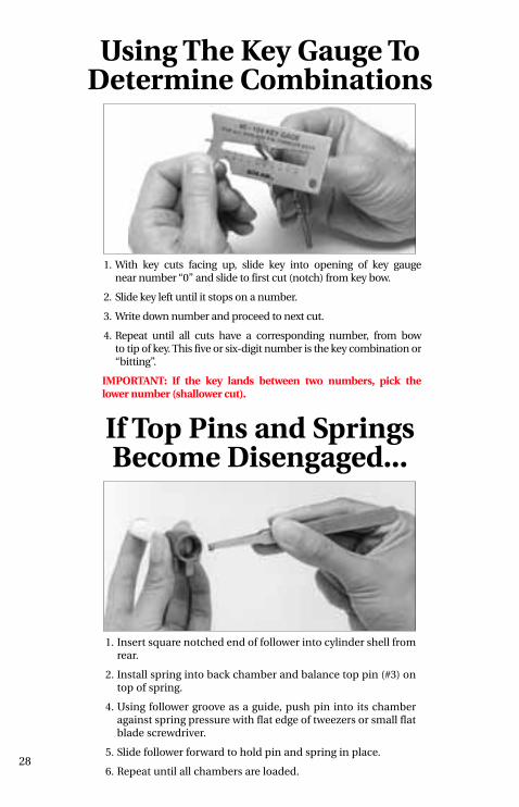
Using The Key Gauge ToDetermine Combinations
1. With key cuts facing up, slide key into opening of key gauge near number “0” and slide to first cut (notch) from key bow.
2. Slide key left until it stops on a number.
3. Write down number and proceed to next cut.
4. Repeat until all cuts have a corresponding number, from bowto tip of key. This five or six-digit number is the key combination or“bitting”.
IMPORTANT: If the key lands between two numbers, pick the lower number (shallower cut).
1. Insert square notched end of follower into cylinder shell fromrear.
2. Install spring into back chamber and balance top pin (#3) ontop of spring.
4. Using follower groove as a guide, push pin into its chamberagainst spring pressure with flat edge of tweezers or small flatblade screwdriver.
5. Slide follower forward to hold pin and spring in place.
6. Repeat until all chambers are loaded.
If Top Pins and Springs Become Disengaged...
28

29
Glossary of TermsANSI American National Standards Institute.
backset The distance from the edge of door to the center line of prep.
bottom pin A bullet-shaped tumbler that comes in a variety of lengths thatcorrespond to the depths of the key cuts.
chassis The body of the lock itself, without any trim.
cylinder The portion of a lock comprised of the plug, shell, pins (tumblers) andsprings. A properly cut key allows the plug to rotate the tailpiece ordrive mechanism which unlocks the lock.
hand The direction a door swings, always referenced from the outside.
housing A larger portion of some cylinder assemblies which encases thecylinder (plug and shell).
latchbolt A spring operated bolt with a beveled face to permit latching action whendoor closes.
master pin A cylindrical shaped tumbler which is flat on both ends, placedbetween the top and bottom pin to create an additional shear line.
pin tumbler Today’s standard tumbler mechanism consists of a series of bottom pin,mechanism top pin and spring for each cut (notch) of the key.
pin tumblers Small sliding pins in a lock cylinder that work against coil springs. They prevent the cylinder plug from rotating unless all are alignedsimultaneously by cuts of the proper depths in the key.
plug The portion of a cylinder which contains the keyway and whichrotates with the key.
rose A circular trim plate attached to the door under the knob or lever.
shear line The area where the top surface of the cylinder plug and inside surfaceof the shell meet, and the height to which the bottom pins must be raisedby the key in order to rotate the plug.
shell The portion of the cylinder immediately surrounding the plug.
strike The metal plate recessed in the frame that receives latch or bolt when the door is closed.
top pin A cylindrical shaped tumbler which is flat on both ends and isinstalled directly under a coil spring in its chamber.
tailpiece A usually flat actuator which extends from the back of the cylinderplug and engages in the lock to operate the latch or bolt.

30
NOTES

31
NOTES

© 2004 Ingersoll-Rand • P 513-325 • Rev. 1/04 • Printed in U.S.A.
IR Security & Safety
SCHLAGE800-847-1864800-452-0663 Faxwww.schlagelock.com
111 Congressional Blvd, Suite 200Carmel, IN 46032(800) 847-1864
Customer Service
14505 West 100th StreetLenexa, KS 66215Order Processing(800) 847-1864
Schlage Distribution Service Center
P.O. Box 2970Shawnee Mission, KS 66201-137014505 West 100th StreetLenexa, KS 66215(800) 847-1864(913) 541-8881FAX (800) 365-5625
International Division
IR Security & Safety1076 Lakeshore Road EastMississauga, Ontario L5E 1E4Canada(877) 590-4734(905) 403-1800FAX (905) 270-1413
Visit Schlage on the web
www.schlagelock.com
Administrative Offices