re-s1 operator’s manual - authorised topcon dealer material of topcon positioning systems (tps)....
TRANSCRIPT
SYNERGY POSITIONING SYSTEMS 3/52 Arrenway Drive, Albany Auckland, New Zealand Free Call: 0800-867-266 Phone: +64-9-476-5151 Fax: +64-9-476-5140 Email: [email protected] Website: www.synergypositioning.co.nz

P O S I T I O N I N G S Y S T E M S
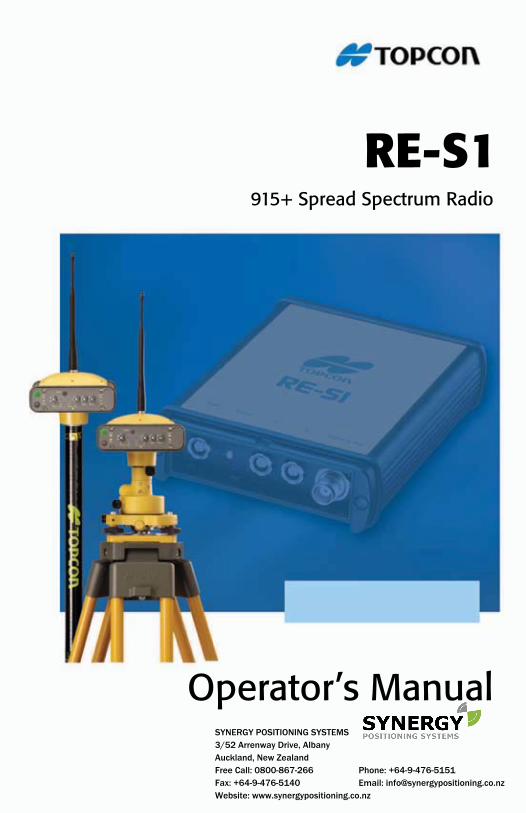
RE-S1Operator’s Manual
Part Number 7010-0780
Rev A
©Copyright Topcon Positioning Systems, Inc.
September, 2006
All contents in this manual are copyrighted by Topcon. All rights reserved. The information contained herein may not be used, accessed, copied, stored,
displayed, sold, modified, published, or distributed, or otherwise reproduced without express written consent from Topcon.
Terms and ConditionsThank you for buying this Topcon product. This document has been prepared to assist you with the care and operation of the product and its use is subject to the following.
USE This product is designed to be used by a professional. The user should have a good knowledge of the safe use of the product and implement the types of safety procedures recommended by the local government protections agency for both private use and commercial job sites.
Copyrights All information contained in this Manual is the intellectual property of, and copyrighted material of Topcon Positioning Systems (TPS). All rights are reserved. You may not use, access, copy, store, display, create derivative works of, sell, modify, publish, distribute, or allow any third party access to, any graphics, content, information or data in this Manual without Topcon’s express written consent and may only use such information for the care and operation of your product. The information and data in this Manual are a valuable asset of TPS and are developed by the expenditure of considerable work, time and money, and are the result of original selection, coordination and arrangement by TPS.
Trademarks The information in this manual is a copyright of Topcon and is for use only with the product. HiPer, RE-S1, and Topcon are trademarks or registered trademarks of Topcon Positioning Systems, Inc. Other product and company names mentioned herein may be trademarks of their respective owners.
DISCLAIMER OF WARRANTY EXCEPT FOR ANY WARRANTIES IN AN APPENDIX OR A WARRANTY CARD ACCOMPANYING THE PRODUCT, THIS MANUAL AND THE PRODUCTS ARE PROVIDED “AS-IS.” THERE ARE NO OTHER WARRANTIES. TPS DISCLAIMS ANY IMPLIED WARRANTY OF MERCHANTABILITY OR FITNESS FOR ANY PARTICULAR USE OR PURPOSE. TPS AND ITS DISTRIBUTORS SHALL NOT BE LIABLE FOR TECHNICAL OR EDITORIAL ERRORS OR OMISSIONS CONTAINED HEREIN; NOR FOR INCIDENTAL OR CONSEQUENTIAL DAMAGES RESULTING FROM THE FURNISHING, PERFORMANCE OR USE OF THIS MATERIAL OR THE PRODUCT. SUCH DISCLAIMED DAMAGES INCLUDE BUT ARE NOT LIMITED TO LOSS OF TIME, LOSS OR DESTRUCTION OF DATA, LOSS OF PROFIT, SAVINGS OR REVENUE, OR LOSS OF THE PRODUCT’S USE. IN ADDITION TPS IS NOT RESPONSIBLE OR LIABLE FOR DAMAGES OR COSTS INCURRED IN CONNECTION WITH OBTAINING SUBSTITUTE PRODUCTS OR SOFTWARE, CLAIMS BY OTHERS, INCONVENIENCE, OR ANY OTHER COSTS. IN ANY EVENT, TPS SHALL HAVE NO LIABILITY FOR DAMAGES OR OTHERWISE TO YOU OR ANY OTHER PERSON OR ENTITY IN EXCESS OF THE PURCHASE PRICE FOR THE PRODUCT.
Website and Other Statements No statement contained at the TPS website (or any other website) or in any other advertisements or TPS literature or made by an employee or independent contractor of TPS modifies these Terms and Conditions (including the Software license, warranty and limitation of liability).
Safety Improper use of the Product can lead to injury to persons or property and/or malfunction of the product. The product should only be repaired by authorized TPS warranty service centers. Users should review and heed the safety warnings in Manual.
Miscellaneous The above Terms and Conditions may be amended, modified, superseded, or canceled, at any time by TPS. The above Terms and Conditions will be governed by, and construed in accordance with, the laws of the State of California, without reference to conflict of laws.All information, illustrations, and applications contained herein are based on the latest available information at the time of publication. Topcon reserves the right to make product changes at any time without notice.
ECO#2853
TOC
Table of Contents
Chapter 1Introduction .......................................................... 1Getting Acquainted .......................................................... 2RX/TX LED .............................................................. 2Ports ........................................................................... 3Radio Modem Antenna ............................................. 3Standard Kit Cables and Power Supply .................... 4
Chapter 2RE-S1 Configuration ............................................ 5
Installing Modem-TPS ..................................................... 5Configuring the RE-S1 as a Repeater .............................. 6
Appendix ASpecifications ....................................................... 9
Appendix BRegulatory Information and Safety Warnings ... 13
FCC Compliance ............................................................. 13Canadian Emissions Labeling Requirements .................. 14Community of Europe Compliance ................................. 14WEEE Directive .............................................................. 14Safety and Usage Warnings ............................................. 15
Appendix CWarranty Terms .................................................... 17
P/N 7010-0780 i

Table of Contents
Notes:
RE-S1 Operator’s Manualii
Chapter 1
Introduction
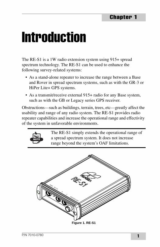
The RE-S1 is a 1W radio extension system using 915+ spread spectrum technology. The RE-S1 can be used to enhance the following survey-related systems:• As a stand-alone repeater to increase the range between a Base and Rover in spread spectrum systems, such as with the GR-3 or HiPer Lite+ GPS systems.
• As a transmit/receive external 915+ radio for any Base system, such as with the GB or Legacy series GPS receiver.
Obstructions—such as buildings, terrain, trees, etc—greatly affect the usability and range of any radio system. The RE-S1 provides radio repeater capabilities and increase the operational range and effectivity of the system in unfavorable environments.
Figure 1. RE-S1
NOTE
The RE-S1 simply extends the operational range of a spread spectrum system. It does not increase range beyond the system’s OAF limitations.
PWR RX/TX A C MODEM ANT
P/N 7010-0780 1
Introduction
Getting AcquaintedThe RE-S1 is a transmit/receive/repeat 915+ spread spectrum radio modem. The RE-S1 is compatible with existing Topcon spread spectrum radio systems (some older HiPer models may need a radio modem upgrade), as well as Topcon base stations. Simple features allow the RE-S1 to be easily adaptable to any situation, and make it easy to use.
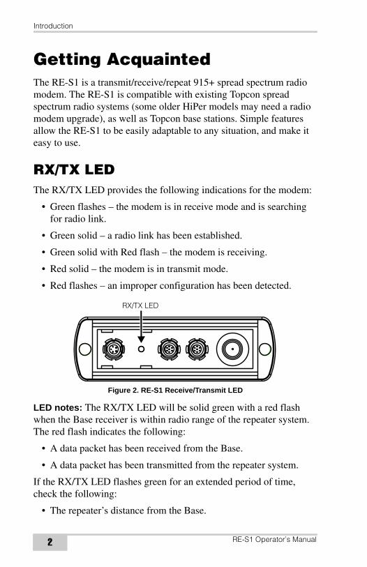
RX/TX LEDThe RX/TX LED provides the following indications for the modem:
• Green flashes – the modem is in receive mode and is searching for radio link.
• Green solid – a radio link has been established.
• Green solid with Red flash – the modem is receiving.
• Red solid – the modem is in transmit mode.
• Red flashes – an improper configuration has been detected.
Figure 2. RE-S1 Receive/Transmit LED
LED notes: The RX/TX LED will be solid green with a red flash when the Base receiver is within radio range of the repeater system. The red flash indicates the following:
• A data packet has been received from the Base.
• A data packet has been transmitted from the repeater system.
If the RX/TX LED flashes green for an extended period of time, check the following:
• The repeater’s distance from the Base.
RX/TX LED
RE-S1 Operator’s Manual2

Getting Acquainted
• The channel of the RE-S1, Base, and Rover.
• The protocol of the RE-S1, Base, and Rover (FH915 Plus).
PortsThe RE-S1 has the following ports:
• Power Port – used to connect the repeater an external power source.
• Serial Ports A and C – used for communication between the repeater and an external device (computer or controller).
• Modem Antenna Port – provides connection to a spread spectrum reverse TNC radio antenna to receive/transmit a radio signal.
Figure 3. RE-S1 Ports
Radio Modem AntennaThe spread spectrum modem antenna is a reverse polarity TNC RF connection (p/n 30-030012-01).
Figure 4. Modem Antenna
Power Port A Port C Modem Antenna Port
SS Antenna
P/N 7010-0780 3
Introduction
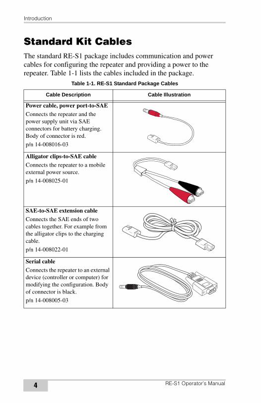
Standard Kit CablesThe standard RE-S1 package includes communication and power cables for configuring the repeater and providing a power to the repeater. Table 1-1 lists the cables included in the package.
Table 1-1. RE-S1 Standard Package Cables
Cable Description Cable Illustration
Power cable, power port-to-SAE
Connects the repeater and the power supply unit via SAE connectors for battery charging. Body of connector is red.
p/n 14-008016-03
Alligator clips-to-SAE cable
Connects the repeater to a mobile external power source.
p/n 14-008025-01
SAE-to-SAE extension cableConnects the SAE ends of two cables together. For example from the alligator clips to the charging cable.
p/n 14-008022-01
Serial cable
Connects the repeater to an external device (controller or computer) for modifying the configuration. Body of connector is black.
p/n 14-008005-03
RE-S1 Operator’s Manual4
Chapter 2
RE-S1 Configuration
Once the RE-S1 is configured, it simply needs to be connected to a power source to begin operating.Installing Modem-TPSModem-TPS is a configuration program for the radio modem board inside the unit. Modem-TPS is available from the TPS website or on the GPS+ CD.
Computer requirements for Modem-TPS are: Windows® 98 or newer and an RS-232C port. Use Modem-TPS version 2.0 or newer to correctly configure the RE-S1.
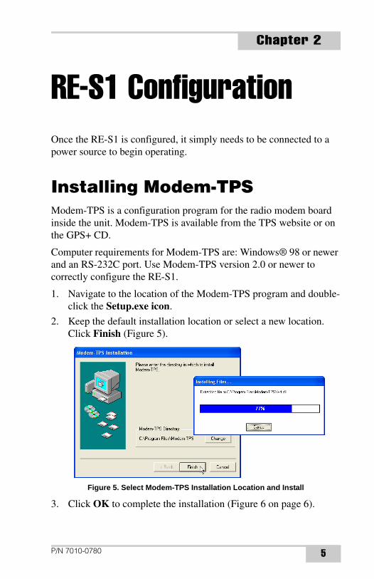
1. Navigate to the location of the Modem-TPS program and double-click the Setup.exe icon.
2. Keep the default installation location or select a new location. Click Finish (Figure 5).
Figure 5. Select Modem-TPS Installation Location and Install
3. Click OK to complete the installation (Figure 6 on page 6).
P/N 7010-0780 5
RE-S1 Configuration
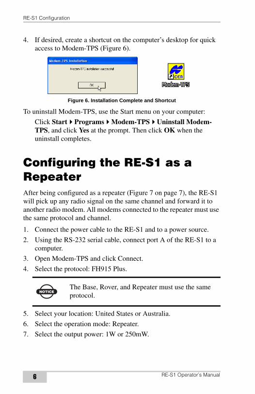
4. If desired, create a shortcut on the computer’s desktop for quick access to Modem-TPS (Figure 6).
Figure 6. Installation Complete and Shortcut
To uninstall Modem-TPS, use the Start menu on your computer:
Click Start Programs Modem-TPS Uninstall Modem-TPS, and click Yes at the prompt. Then click OK when the uninstall completes.
Configuring the RE-S1 as a RepeaterAfter being configured as a repeater (Figure 7 on page 7), the RE-S1 will pick up any radio signal on the same channel and forward it to another radio modem. All modems connected to the repeater must use the same protocol and channel.
1. Connect the power cable to the RE-S1 and to a power source.
2. Using the RS-232 serial cable, connect port A of the RE-S1 to a computer.
3. Open Modem-TPS and click Connect.
4. Select the protocol: FH915 Plus.
5. Select your location: United States or Australia.
6. Select the operation mode: Repeater.
7. Select the output power: 1W or 250mW.
NOTICEThe Base, Rover, and Repeater must use the same protocol.
RE-S1 Operator’s Manual6
Configuring the RE-S1 as a Repeater
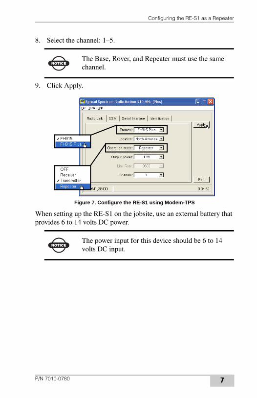
8. Select the channel: 1–5.
9. Click Apply.
Figure 7. Configure the RE-S1 using Modem-TPS
When setting up the RE-S1 on the jobsite, use an external battery that provides 6 to 14 volts DC power.
NOTICEThe Base, Rover, and Repeater must use the same channel.
NOTICEThe power input for this device should be 6 to 14 volts DC input.
P/N 7010-0780 7

RE-S1 Configuration
Notes:
RE-S1 Operator’s Manual8
Appendix A
Specifications
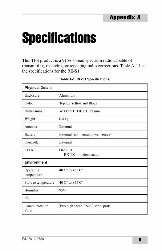
This TPS product is a 915+ spread spectrum radio capable of transmitting, receiving, or repeating radio corrections. Table A-1 lists the specifications for the RE-S1.Table A-1. RE-S1 Specifications
Physical Details
Enclosure Aluminum
Color Topcon Yellow and Black
Dimensions W:145 x H:110 x D:35 mm
Weight 0.4 kg
Antenna External
Battery External (no internal power source)
Controller External
LEDs One LED:RX TX – modem status
Environment
Operating temperature
40 C° to +55 C°
Storage temperature 40 C° to +75 C°
Humidity 95%
I/O
Communication Ports
Two high speed RS232 serial ports
P/N 7010-0780 9

Specifications
Port specifications RS232 Serial PortBaud rate: 460800,230400,115200(Default),57600,
38400,19200,9600,4800,2400,1200,600, 300Flow control: RTS/CTSLength: 7,8 (default)Sop bit: 1 (default), 2Parity: None (default), Odd, Even
Connectors Modem Antenna (reverse polarity TNC), PWR, RS232
MINTER One LED (see “LEDs” on page 9 for details)
General Modem Details
Frequency Rangecountry/region/purpose dependent
902 to 928 MHz, United States915 to 925 MHz, Australia
Signal structuring Frequency-hopping spread spectrum
Hopping pattern 5 per band, user-selectable
Hopping channels 128
Occupied bandwidth
100 KHz
Frequency modulation technique
FSK, 64 Kbps
System gain 29 dB
Operation mode Transmitter, Receiver, Repeater
Protocol FH915, FH915+
Data communications
Serial interface RS232
Serial data rate 9600, 19200, 38400, 57600 bps, user selectable
Effective radio link rate
9600, 10200, 17000, 51000 bpsUser selectable for FH915; automatic selection for FH915+
Error correction FEC (15.7), majority decoding
Table A-1. RE-S1 Specifications (Continued)
RE-S1 Operator’s Manual10
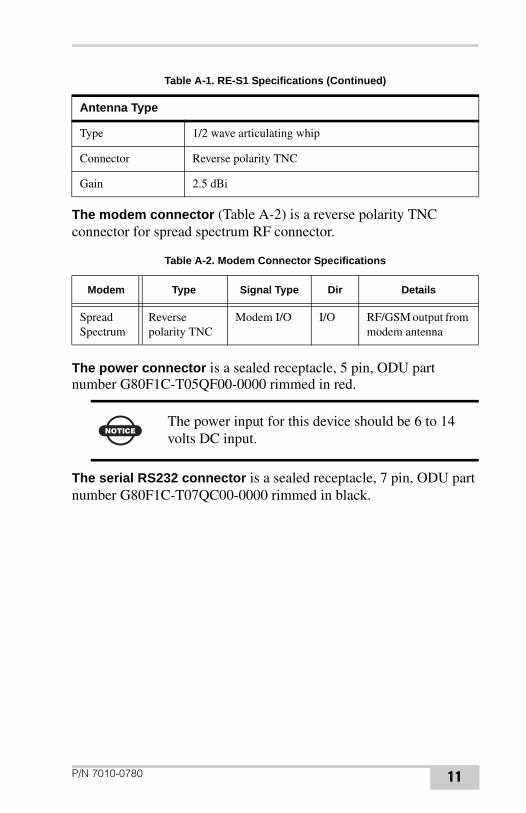
The modem connector (Table A-2) is a reverse polarity TNC connector for spread spectrum RF connector.
The power connector is a sealed receptacle, 5 pin, ODU part number G80F1C-T05QF00-0000 rimmed in red.
The serial RS232 connector is a sealed receptacle, 7 pin, ODU part number G80F1C-T07QC00-0000 rimmed in black.
Antenna Type
Type 1/2 wave articulating whip
Connector Reverse polarity TNC
Gain 2.5 dBi
Table A-2. Modem Connector Specifications
Modem Type Signal Type Dir Details
Spread Spectrum
Reverse polarity TNC
Modem I/O I/O RF/GSM output from modem antenna
NOTICEThe power input for this device should be 6 to 14 volts DC input.
Table A-1. RE-S1 Specifications (Continued)
P/N 7010-0780 11

Specifications
Notes:
RE-S1 Operator’s Manual12
Appendix B
Regulatory Information and Safety Warnings
The following sections provide information on this product’s compliance with government regulations for use, and some guidelines on the safe use of the product.FCC ComplianceThis device complies with Part 15 of the FCC rules. Operation is subject to the following two conditions:
1. This device may not cause harmful interference, and
2. This device must accept any interference received, including interference that may cause undesired operation.
This equipment has been tested and found to comply with the limits for a digital device, pursuant to Part 15 of the FCC rules. These limits are designed to provide reasonable protection against harmful interference in residential installations. This equipment generates, uses, and can radiate radio frequency energy, and if not installed and used in accordance with the instructions, may cause harmful interference to radio communications. However, there is no guarantee that interference will not occur in a particular installation.
If this equipment does cause interference to radio or television equipment reception, which can be determined by turning the equipment off and on, the user is encouraged to try to correct the interference by one or more of the following measures:
• Reorient or relocate the receiving antenna.
• Move the equipment away from the receiver.
P/N 7010-0780 13

Regulatory Information and Safety Warnings
• Plug the equipment into an outlet on a circuit different from that to which the receiver is powered.
• Consult the dealer or an experienced radio/television technician for additional suggestions.
Canadian Emissions Labeling RequirementsThis Class B digital apparatus meets all requirements of the Canadian Interference-Causing Equipment Regulations.
Cet appareil numérique de la classe B respecte toutes les exigences du Réglement sur le matériel brouilleur du Canada.
Community of Europe ComplianceThe product described in this manual is in compliance with the R&TTE and EMC directives from the European Community.
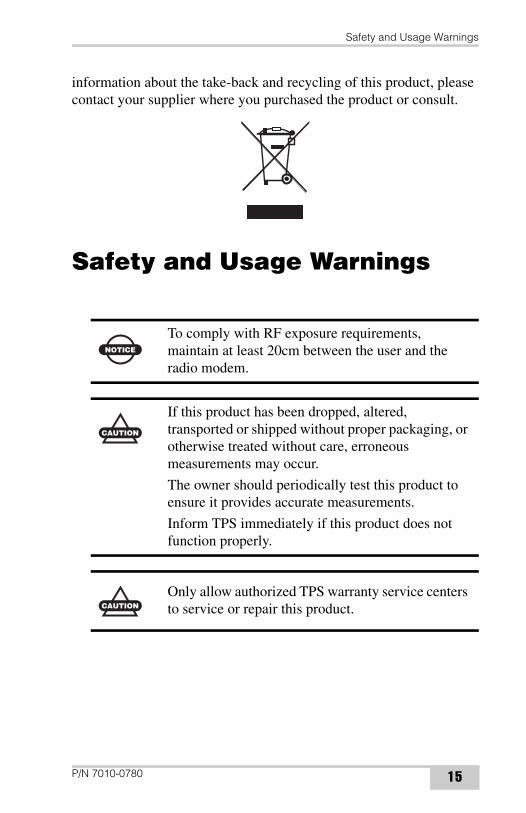
WEEE DirectiveFollowing information is for EU-member states only:
The use of the symbol indicates that this product may not be treated as household waste. By ensuring this product is disposed of correctly, you will help prevent potential negative consequences for the environment and human health, which could otherwise be caused by inappropriate waste handling of this product. For more detailed
CAUTION
Any changes or modifications to the equipment not expressly approved by the party responsible for compliance could void your authority to operate such equipment.
RE-S1 Operator’s Manual14
Safety and Usage Warnings
information about the take-back and recycling of this product, please contact your supplier where you purchased the product or consult.
Safety and Usage Warnings
NOTICE
To comply with RF exposure requirements, maintain at least 20cm between the user and the radio modem.
CAUTION
If this product has been dropped, altered, transported or shipped without proper packaging, or otherwise treated without care, erroneous measurements may occur.
The owner should periodically test this product to ensure it provides accurate measurements.
Inform TPS immediately if this product does not function properly.
CAUTION
Only allow authorized TPS warranty service centers to service or repair this product.
P/N 7010-0780 15

Regulatory Information and Safety Warnings
Notes:
RE-S1 Operator’s Manual16
Appendix C
Warranty Terms
TPS laser and electronic positioning equipment are guaranteed against defective material and workmanship under normal use and application consistent with this Manual. The equipment is guaranteed for the period indicated, on the warranty card accompanying the product, starting from the date that the product is sold to the originalpurchaser by TPS’ Authorized Dealers.1
During the warranty period, TPS will, at its option, repair or replace this product at no additional charge. Repair parts and replacement products will be furnished on an exchange basis and will be either reconditioned or new. This limited warranty does not include service to repair damage to the product resulting from an accident, disaster, misuses, abuse or modification of the product.
Warranty service may be obtained from an authorized TPS warranty service dealer. If this product is delivered by mail, purchaser agrees to insure the product or assume the risk of loss or damage in transit, to prepay shipping charges to the warranty service location and to use the original shipping container or equivalent. A letter should accompany the package furnishing a description of the problem and/or defect.
The purchaser’s sole remedy shall be replacement as provided above. In no event shall TPS be liable for any damages or other claim including any claim for lost profits, lost savings or other incidental or consequential damages arising out of the use of, or inability to use, the product.
1. The warranty against defects in a Topcon battery, charger, or cable is 90 days.
P/N 7010-0780 17

Warranty Terms
Notes:
RE-S1 Operator’s Manual18

Notes:
Notes

Notes:
Notes


Topcon Positioning Systems, Inc.7400 National Drive, Livermore, CA 94551
800∙443∙4567 www.topcon.com
ISO 9001:2000FM 68448
RE-S1 Operator’s ManualP/N: 7010-0780 Rev A 09/06 30
©2006 Topcon Corporation All rights reserved. No unauthorized duplication.