r-net control system on-board...
TRANSCRIPT
.
R-NET CONTROL
SYSTEM
ON-BOARD PROGRAMMING
MANUAL
SK78571/3

R-NET OBP MANUAL PG DRIVES TECHNOLOGY
© PG Drives Technology 2008
All rights reserved.
This manual is furnished under copyright and may only be used in accordance with the terms laid out by PG Drives Technology.
The information in this manual is furnished for informational use only, is subject to change without notice, and should not be construed as a commitment by PG Drives Technology.
Except as permitted by such terms, no part of this manual may be reproduced, stored in a retrieval system, or transmitted, in any form or be any means electronic, mechanical, recording, or otherwise - without the prior written permission of PG Drives Technology. +44 (0)1425 271444
SK78571/3 2
PG DRIVES TECHNOLOGY R-NET OBP MANUAL
About this manual.......................................
Chapter 1 – Programming..................................
1 Introduction.....................................
2 Entering On-Board Programming ...
2.2 Navigating the OBP Screens ...................
2.3 Making an Adjustment............................
3 Programmable Parameters .............
4 Drive................................................
4.1 Power ......................................................
4.2 Torq - (Torque) .........................................
4.3 Trmr - (Tremor Damping) .........................
5 Controls...........................................
:: Global ::.........................................................
5.1 Steer Correct...........................................
5.2 Sounder Volume .....................................
5.3 Endstop Beep - (Actuator Endstop Beep
5.4 Act. Entry Axis - (Actuator Entry Axis).........
5.5 Chge Prf in Drv - (Change Profile while D
5.6 Speed Adjust...........................................
5.7 Spd Adj in Drv - (Speed Adjust while Drivi
5.8 Momentary Screens................................
5.9 Rev Driving Alarm - (Reverse Driving Alarm
5.10 Emergency Stop - (Emergency Stop Swit
5.11 Lock Fn Enable – (Lock Function Enabled
5.12 Display Speed.........................................
5.13 Max Display Speed – (Maximum Display
5.14 Power-up Mode – (Power-Up Mode).......
:: Profiled ::........................................................
5.15 Sleep - (Sleep Timer) ...............................
5.16 CMid - (Change Mode While Driving) .....
5.17 Background ............................................
:: Joystick :: .......................................................
5.18 Active Throw............................................
5.19 Throw Detail ............................................
5.20 Active Orientation ...................................
5.21 Orientation Detail....................................
5.22 Deadband..............................................
:: Standby :: ......................................................
5.23 SwSby - (Switch to Stdby).........................
5.24 SbyTm - (Standby Time)...........................
SK78571/3
TABLE OF CONTENTS
5.25 MdeSl - (Mode Select)................................................18 .................. 5 5.26 Remsl - (Remote Select).............................................18
6 Latched........................................................... 19 ...........................6
6.1 Drive ...........................................................................19 .................. 8
6.2 Acts - (Actuators) ........................................................19 ................... 8 6.4 Bleep - (Timeout Bleep) ..............................................20
7 ISM Actuators................................................... 20 ..................... 9 ..................... 9 7.1 UpSpd - (Up Speed)....................................................20 ................ 10 7.2 DnSpd - (Down Speed)...............................................20
7.3 Acc - (Acceleration) ...................................................20 ................ 12 7.4 Dec - (Deceleration)...................................................21
................... 12 8 SM Actuators.................................................... 21 ................... 12
8.1 Up Speed - (UpSpd)....................................................21 ................... 12 8.2 Down Speed - (DnSpd)...............................................21 ................ 13
9 Profiles ............................................................. 22 ................... 13 9.1 PrfEn - (Profile Enable) .................................................22 ................... 13
10 Modes ............................................................. 22 ................... 13 ) .................. 13 10.1 Prf - (Mode Enabled) ..................................................22 ................... 13 11 Input Devices .................................................. 22 riving) .......... 13
11.1 Type - (ID Type) ...........................................................22 ................... 13
12 System ............................................................. 23 ng) .............. 13
12.1 Diagnostics.................................................................23 ................... 14 12.2 Timers .........................................................................23 )................ 14 12.3 Joystick Calibration ....................................................23 ch) ............. 14 12.4 Copy Profiles ..............................................................23 ) ................ 14 12.4 Load Presets - To be included in future releases. .......23 ................... 14 12.5 Adjust Contrast ...........................................................23 ed Speed) .. 15
13 OBP Quick Reference Guide ........................... 24 ................... 15 ................... 15 ................... 15 Chapter 2 – Diagnostics............................................................26 ................... 15 1 Introduction..................................................... 28 ................... 15
1.1 Diagnostic Procedure.................................................28 ................... 16
2 Diagnostic Screens.......................................... 28 ................... 16 2.1 Current Diagnostic Screen .........................................28 ................... 16 2.1.1 Identified Module.......................................................29 ................... 16 2.1.2 Trip Text.......................................................................29 ................... 17 2.1.3 Trip Code ...................................................................29 ................... 17 2.1.4 Example .....................................................................29 ................... 17 2.2 System Log Screen.....................................................29 ................... 17
2.3 Connections.................................................... 31 ................... 18
3
R-NET OBP MANUAL PG DRIVES TECHNOLOGY
2.7 Acts - (Actuators) ........................................................44 3 Diagnostic Text Definitions............................... 32 2.8 Time - (Timeout) ..........................................................44 3.1 Joystick Error............................................................... 32 2.9 Acc - (Acceleration) ...................................................44 3.2 Low Battery................................................................. 33 2.10 Dec - (Deceleration) ..................................................44 3.3 High Battery Voltage .................................................. 33 2.11 Introduction................................................................44 3.4 Brake Error .................................................................. 33 2.12 PM Memory Error ........................................................44 3.5 Motor Error.................................................................. 33 2.13 Basic Tests ..................................................................44 3.6 Inhibit Active .............................................................. 33 2.14 Servicing of Defective Units ........................................45 3.7 Joystick Calibration Error ............................................ 33
3.8 Latched Timeout........................................................ 34 3.9 Brake Lamp Short....................................................... 34 3.10 Lamp Short ................................................................ 34 3.11 Indicator Lamp Short ................................................. 34 3.12 Indicator Lamp Failed ............................................... 34 3.13 Over-current............................................................... 34 3.14 Overtemp (acts) ........................................................ 35 3.15 Overtemp (lamps) ..................................................... 35 3.16 DIME Error................................................................... 35 3.17 Memory Error.............................................................. 35 3.18 PM Memory Error........................................................ 35 3.19 Bad Cable ................................................................. 36 3.20 Bad Settings ............................................................... 36 3.21 Module Error............................................................... 36 3.22 System Error................................................................ 36 3.23 SID Disconnected ...................................................... 37 3.24 User Switch Detached................................................ 37 3.25 Gone to Sleep ........................................................... 37 3.26 Charging ................................................................... 37
4 Basic Tests ....................................................... 38 4.1 General Inspection .................................................... 38 4.2 Brake Test ................................................................... 38 4.3 Drive Test.................................................................... 38 4.4 Gradient Test.............................................................. 38 4.5 Lights, Indicators and Hazard Lamps Test .................. 39 4.6 Actuator Test .............................................................. 39 46.7 Inhibit Input Test ......................................................... 39
5 Servicing of Defective Units ............................. 40
Chapter 3 – Warning Summary ...........................................41 1 Introduction..................................................... 43
2.1 Introduction ............................................................... 43 2.2 Entering OBP Mode.................................................... 43 2.3 Trmr - (Tremor Damping) ............................................ 43 2.4 Emergency Stop (Emergency Stop Switch)................ 43 2.5 Latched ..................................................................... 43 2.6 Drive........................................................................... 44
SK78571/3 4

PG DRIVES TECHNOLOGY R-NET OBP MANUAL
About this manual
The Technical Manual gives an introduction to the R-net Input/Output Module (IOM).
Throughout the manual icons are used to draw the reader’s attention.
The icons used are:
Note - A general point for best practice.
Caution - A point of safety which if ignored could result in damage to the Control System or the vehicle.
Warning - A point of safety which if ignored could cause injury to the individual.
PG Drives Technology accept no liability for any losses of a-ny kind if the points are not followed.
SK78571/3 5
R-NET OBP MANUAL – PROGRAMMING PG DRIVES TECHNOLOGY
CHAPTER 1 – PROGRAMMING
SK78571/3 6

PG DRIVES TECHNOLOGY R-NET TECHNICAL MANUAL – PROGRAMMING
SK78571/3 7
R-NET OBP MANUAL – PROGRAMMING PG DRIVES TECHNOLOGY
1 Introduction
The main advantage of using programmable control systems is that they can be easily tailored to the specific needs and capabilities of a particular vehicle, while taking into account safe performance characteristics.
The programmable control system achieves this great flexibility by referring to a set of internal parameters which govern factors such as the vehicle’s speed, acceleration and braking. These parameters can be changed over a wide span to suit different vehicles and users.
It is possible to set up a control system so that it is unsuitable for some uses and possibly even some vehicles. Take care when programming a control system and if you need any advice in programming or selecting values, please contact PGDT.
Programming should only be conducted by healthcare professionals with in-depth knowledge of PGDT control systems. Incorrect programming could result in an unsafe set-up of a wheelchair for a user. PGDT accept no responsibility for losses of any kind if the programming of the control system is altered from the factory pre-set values.
2 Entering On-Board Programming
OBP in field can be entered via two methods – connection of a hardware dongle or a keycode. The actual method required is set by the factory programming of the control system.
OBP is not possible using an LED Joystick Module.
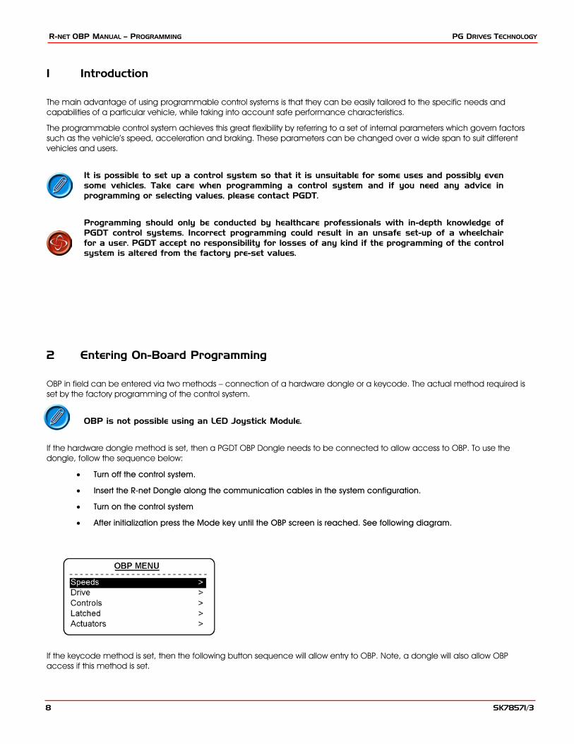
If the hardware dongle method is set, then a PGDT OBP Dongle needs to be connected to allow access to OBP. To use the dongle, follow the sequence below:
• Turn off the control system.
• Insert the R-net Dongle along the communication cables in the system configuration.
• Turn on the control system
• After initialization press the Mode key until the OBP screen is reached. See following diagram.
If the keycode method is set, then the following button sequence will allow entry to OBP. Note, a dongle will also allow OBP access if this method is set.
SK78571/3 8
PG DRIVES TECHNOLOGY R-NET TECHNICAL MANUAL – PROGRAMMING
• Hold down the Horn button and then hold down the On/Off button until there is a short bleep.
• Power-up sound will occur prior to this bleep.
• Release the Horn button, but continue to hold down the On/Off button until there is a further short bleep.
• Release the On/Off button, there will now be a longer bleep and OBP mode will be entered. See previous diagram.
If the keycode method is set, then it may be possible for a wheelchair user to gain entry to the OBP function. PGDT accept no liability for losses of any kind if this method of OBP is set. PGDT also accept no liability for losses of any kind if OBP access is gained by unauthorised personnel obtaining a dongle.
2.2 Navigating the OBP Screens
Whilst in OBP deflecting the joystick to the left, whilst the parameter title is highlighted, will display an elongated version of the parameter name.
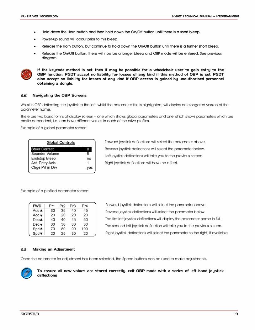
There are two basic forms of display screen – one which shows global parameters and one which shows parameters which are profile dependent, i.e. can have different values in each of the drive profiles.
Example of a global parameter screen:
Forward joystick deflections will select the parameter above.
Reverse joystick deflections will select the parameter below.
Left joystick deflections will take you to the previous screen.
Right joystick deflections will have no effect.
Example of a profiled parameter screen:
Forward joystick deflections will select the parameter above.
Reverse joystick deflections will select the parameter below.
The first left joystick deflections will display the parameter name in full.
The second left joystick deflection will take you to the previous screen.
Right joystick deflections will select the parameter to the right, if available.
2.3 Making an Adjustment
Once the parameter for adjustment has been selected, the Speed buttons can be used to make adjustments.
To ensure all new values are stored correctly, exit OBP mode with a series of left hand joystick deflections
SK78571/3 9
R-NET OBP MANUAL – PROGRAMMING PG DRIVES TECHNOLOGY
3 Programmable Parameters
Speeds
Forward
Fwd Accel Max Sets maximum forward acceleration
Fwd Accel Min Sets minimum forward acceleration
Fwd Decel Min Sets maximum forward deceleration
Fwd Decel Max Sets minimum forward deceleration
Fwd Speed Max Sets maximum forward speed
Fwd Speed Min Sets minimum forward speed
Reverse
Rev Accel Max Sets maximum reverse acceleration
Rev Accel Min Sets minimum reverse acceleration
Rev Decel Min Sets maximum reverse deceleration
Rev Decel Max Sets minimum reverse deceleration
Rev Speed Max Sets maximum reverse speed
Rev Speed Min Sets minimum reverse speed
Turn
Turn Accel Max Sets maximum turning acceleration
Turn Accel Min Sets minimum turning acceleration
Turn Decel Min Sets maximum turning deceleration
Turn Decel Max Sets minimum turning deceleration
Turn Speed Max Sets maximum turning speed
Turn Speed Min Sets minimum turning speed
Drive
Power Reduces power to minimize risk of indoor fittings damage
Torque Torque boost to overcome obstacles at low speed settings
Tremor Damping Adjustable damping to reduce the effect of hand tremor
Controls
Global Controls
Steer Correct Adjusts the PM output’s to compensate for mis-matched motors
Sounder Volume Sets volume of audible feedback from JSM.
Endstop Bleep Sets whether there is a bleep when a seat axis reaches endstop
Act. Entry Axis Sets the default axis when seat control mode is entered
Chge Prf in Drv Sets whether profile changes are permissible while driving
Speed Adjust Sets whether the speed buttons on the JSM are active
Speed Adj in Drv Sets whether speed setting changes are permissible while driving
Momentary Screens Sets whether large screens appear at profile and speed changes
Rev Driving Alarm Sets if the reverse driving alarm is active
Em Stop Switch Allows latched operation without the use of an Em Stop switch
Lock Function Enabled Sets how the lock function is activated
Display Speed Sets how the speedometer is displayed in miles per hour or kilometers per hour
Max Dis Speed This sets the operation of the graphical speed display
Power-up Mode This sets the Mode that will be active when the system is powered-up.
Profiled Controls
Sleep Timer Sets the time of inactivity before the system goes to sleep
Chge Mde in Drv Sets whether mode changes are permissible while driving
Background Sets the default background for each profile
Joystick
Active Throw Sets joystick throw via joystick movements
Throw Detail Sets joystick throw via programming
Active Orientation Sets joystick orientation via joystick movements
Orientation Detail Sets joystick orientation via programming
Deadband Sets the joystick deadband (size of neutral position)
Standby
Switch to Stdby Sets whether an external button can be used to enter Standby Mode
Standby Time Sets the time of inactivity before Standby Mode is entered
SK78571/3 10

PG DRIVES TECHNOLOGY R-NET TECHNICAL MANUAL – PROGRAMMING
Mode Select Sets whether other modes can be selected from Standby Mode
Remote Select Sets whether a profile can be selected from Standby Mode
Latched
Drive Selects latched drive operation
Actuators Selects latched actuator operation
Timeout Sets the timeout period for latched operation
Timeout Bleep Sets whether a bleep occurs as the timeout period approaches
ISM Actuators
Up Speed Sets actuator speed in the up direction
Down Speed Sets actuator speed in the down direction
Acceleration Sets actuator acceleration
Deceleration Sets actuator deceleration
SM Actuators
Up Speed Sets actuator axis speed in the up direction
Down Speed Sets actuator axis speed in the down direction
Profiles
Profile Enable Sets which Profiles are available to the user
Modes
Modes Sets which Modes are available to in each Profile
Input Devices
ID Type Sets which Input Device controls a Profile
System
Diagnostics Accesses the system’s error logs
Timers Accesses the system’s run timer
Joystick Calibration Automatic joystick calibration procedure
Copy Profiles Utility to copy one profile to another
Load Presets Restores factory preset values
Adjust Contrast Adjusts the contrast of the LCD screen
SK78571/3 11

R-NET OBP MANUAL – PROGRAMMING PG DRIVES TECHNOLOGY
3 Speeds
This branch contains all the speed, acceleration and deceleration settings for the forward, reverse and turn directions. All parameters are profile dependent and each has both a minimum value and a maximum value. The minimum value is effective at speed setting 1 and the maximum value is effective at speed setting 5. For speed settings 2, 3 and 4, intermediate, linearly spaced values are calculated.
For Acceleration settings, a higher number means the wheelchair will accelerate faster.
For Deceleration settings, a higher number means the wheelchair will brake more severely.
For Speed settings, a higher number means the wheelchair will drive faster.
If a Maximum Parameter is set to a value less than the current value of this parameter, then it will automatically be adjusted to the same as Maximum Forward Speed.
4 Drive
This branch contains profile dependent parameters associated with the drive performance of the wheelchair.
4.1 Power
This reduces the power of the wheelchair. Power is the ability of a wheelchair to climb a hill or overcome an obstacle. If it is set to 100% then the wheelchair will provide full power. Values below 100% will result in reduced power.
A typical use is minimizing damage to doorways or furniture if the wheelchair is being used indoors. The values can be set independently between drive profiles, meaning separate indoor and outdoor profiles can be defined.
Programmable range is 25% to 100% in steps of 1%.
If the value is set to less than 100%, then the boost current function is automatically disabled. I.e. the reduction is applied to the Current Limit Max. value.
Example: R-net is programmed to:
Maximum Current Limit = 80 Amps Boost Drive Current = 120 Amps Boost Drive Time = 5 Seconds
Power (Profile 1) = 100% Power (Profile 2) = 50%
This means that in Profile 1 the system will be able to output 120A for 5 seconds before reducing to 80A, but in Profile 2 will output 50% of 80A = 40A with no boost.
4.2 Torq - (Torque)
This parameter can be used to boost the power to the motors at low drive speeds. This is useful for overcoming obstacles such as door thresholds or thick pile carpets and for countering Roll-back.
Programmable range is 0% to 100% in steps of 1%.
At 0% the parameter has no effect. The recommended value is 80%, however, if the wheelchair drive is considered to be jerky, then reduce this value.
4.3 Trmr - (Tremor Damping)
This parameter can be used to reduce the effects of a user’s hand tremor.
The programmable range is 0% to 100%. The higher the value, the greater the damping that is applied
If using high values of Tremor Damping, pay particular attention to the stopping distance of the wheelchair, as it will be increased.
SK78571/3 12

PG DRIVES TECHNOLOGY R-NET TECHNICAL MANUAL – PROGRAMMING
5 Controls
:: Global ::
5.1 Steer Correct
This parameter is used to compensate for mis-matches in motor speeds, thereby ensuring the wheelchair drives in a straight line when the joystick is deflected straight ahead. This is particulary useful for switch type Input Devices.
The programmable range is –9 to +9 in steps of 1.
If the motors are perfectly matched the parameter setting should be zero.
If the wheelchair is veering to the left, then the value should be increased. Conversely, if the wheelchair is veering to the right, then the value should be increased.
This rule may be reversed if the Motor Swap parameter has been set to yes.
5.2 Sounder Volume
This sets the volume of the audible feedback given whenever a button or switch on the Joystick Module is operated.
The programmable range is 0 to 10 in steps of 1.
If set to 0, there will be no sound given. Higher values will give progressively louder sounds.
5.3 Endstop Beep - (Actuator Endstop Beep)
This sets whether a short beep occurs when an actuator mechanism reaches an end position.
The programmable options are yes and no.
The beep will only occur on actuator mechanisms that use automatic endstop detection, i.e. over-current measurement.
5.4 Act. Entry Axis - (Actuator Entry Axis)
This sets the seat (actuator) adjustment axis that is initially selected when Seating Mode is entered.
The programmable range is 0 to 12. A value of 0 will mean the entry axis will be the one selected the last time the mode was exited. Any other value corresponds to the appropriate axis.
When OBP is enabled and Seating Mode is entered, the axis number will appear in the bottom left corner of the screen.
5.5 Chge Prf in Drv - (Change Profile while Driving)
This sets whether Profile changes are permitted while the wheelchair is driving.
The programmable options are yes and no.
5.6 Speed Adjust
This sets whether the Speed Down and Speed Up buttons on the Joystick Module are active.
The programmable options are yes and no.
5.7 Spd Adj in Drv - (Speed Adjust while Driving)
This sets whether the Speed Down and Speed Up buttons are active while the wheelchair is driving.
The programmable options are yes and no.
SK78571/3 13

R-NET OBP MANUAL – PROGRAMMING PG DRIVES TECHNOLOGY
5.8 Momentary Screens
This sets whether the large, momentary screens appear in between Profile and Speed setting changes.
The programmable options are Yes and No.
5.9 Rev Driving Alarm - (Reverse Driving Alarm)
This sets whether a warning alarm is sounded while the wheelchair is driving in reverse.
The programmable options are yes and no.
5.10 Emergency Stop - (Emergency Stop Switch)
This sets whether an Emergency Stop Switch must be used when latched operation is programmed.
The programmable options are yes and no.
If set to yes, then a normally closed Emergency Stop Switch must be connected into the External Profile Jack on the Joystick Module, whenever latched drive or latched actuator operation is programmed. If such a switch is not fitted, then operation of the wheelchair will be inhibited.
If set to no, then an Emergency Stop Switch is not required. This setting should only be used after a full assessment of the risks involved, i.e. there is no way of effecting an emergency stop from latched drive or actuator operation.
PGDT accept no liability for losses of any kind resulting from the use of a wheelchair with latched drive or actuator operation and with no normally closed Emergency Stop Switch fitted.
5.11 Lock Fn Enable – (Lock Function Enabled)
This sets if and how the R-net may be locked to prevent the wheelchair being used by unauthorised persons.
The programmable options are as follows:
None Means the R-net cannot be locked
Seq Means the keypad locking sequence can lock/unlock the R-net.
(Refer to the R-net Technical Manual – SK77981 for sequence details)
Key Means a PGDT supplied key can lock/unlock the R-net
Both Means either the keypad or a key can be used to lock/unlock the R-net.
5.12 Display Speed
This sets whether the speedometer is displayed in miles per hour or kilometers per hour. Note, the Power Module always calculates and transmits speed information in miles per hour.
The programmable options are Off, mph or km/h.
If set to Off, there will be no speed display on the LCD screen.
If set to mph, then the speed will be displayed as the value transmitted by the Power Module (which always sends the information in miles per hour) and the text ‘mph’ will appear on the LCD screen.
If set to km/h, then the module with the speedometer display will convert the Power Module value into kilometers per hour and the text ‘km/h’ will appear on the LCD screen.
Only certain Input Devices, e.g. CJSM or Omni, have the speedometer function.
SK78571/3 14

PG DRIVES TECHNOLOGY R-NET TECHNICAL MANUAL – PROGRAMMING
5.13 Max Display Speed – (Maximum Displayed Speed)
This calibrates the graphical speed arc to the actual speed of the wheelchair, measured in mph. The value of this parameter should be set to the speed that is required to “fill” the speed arc.
Normally, this will be the same value as Maximum Rated Speed, however, if the wheelchair has been programmed to less than 100% speed, then this value will need changing to ensure the arc “fills” at the new maximum speed.
The programmable range is 0.0mph to 5.0mph in steps of 0.1mph.
Not all JSMs or Input Devices have a speed display function.
5.14 Power-up Mode – (Power-Up Mode)
This sets the Mode that is selected when the system is powered-up.
The programmable options are 1 - 8
You will need a list of the current programmed Modes for the particular R-net you are using to be able to adjust this parameter correctly.
If a Mode is selected but the appropriated Output Module is not present, then the system will default to Drive Mode at power-up.
:: Profiled ::
5.15 Sleep - (Sleep Timer)
This sets the period of joystick (or other type of Input Device) inactivity before the system will automatically power down.
The programmable range is 0 minutes to 30 minutes in steps of 1 minute. If set to a value of 0, then the system will never automatically power-down.
5.16 CMid - (Change Mode While Driving)
This sets whether Profile changes are permitted while the wheelchair is driving.
The programmable options are yes and no.
5.17 Background
This sets the LCD screen background color for each Profile.
The programmable options are Blue and White. Blue is the conventional setting, while White sets a high-contrast screen that may be more easily viewable in very bright conditions. The diagram below shows examples of the two screen types.
Blue
White
Inputs Devices that have color LCD screens have their own local programming for background, which can be set to Blue, White and Auto. If set to Blue or White, then those settings will always occur, but if set to Auto then the setting as determined by this parameter will occur.
SK78571/3 15

R-NET OBP MANUAL – PROGRAMMING PG DRIVES TECHNOLOGY
:: Joystick ::
This branch contains parameters related to the joystick. All parameters are profile dependent.
5.18 Active Throw
This allows programming of the system so that full speed can be reached with a reduced joystick movement (throw). This is particularly useful for wheelchair users with limited hand or arm movement.
In Active Throw, the deflection in each of the four main joystick directions – forward, reverse, left and right – is set interactively with the user.
To set Throw Interactively follow the procedure below:
• Enter OBP and select Controls.
• From the Controls Menu select Joystick.
• From the Joystick Menu select Active Throw.
• From the Throw Menu set which Profiles will be affected by the interactive setting. This is achieved by placing a tick next to the Profiles required and a cross by the Profiles not required. Use the Speed Up and Down buttons to change the setting.
• Once this is complete deflect the joystick to the right while any of the Profiles are Highlighted. This will enter the Interactive Throw programming procedure.
• Follow the on-screen instructions
• After the Reverse direction has been set the R-net will go through a configuration process, an hourglass will be displayed during this time.
• Once the configuration is complete a large tick will be displayed on the screen for a short time and then the Joystick Menu will be displayed.
5.19 Throw Detail
This allows inspection and programming, in the conventional way, of the joystick throw values for each of the Profiles.
The programmable ranges are 25% to 100%.
5.20 Active Orientation
This allows the orientation of the joystick to be changed. For example, exchanging the forward and reverse directions. It is also possible to exchange the forward/reverse axis with the left/right axis.
To set Active Orientation follow the procedure below:
• Enter OBP and select Controls.
• From the Controls Menu select Joystick.
• From the Joystick Menu select Active Orientation.
• From the Orientation Menu set which Profiles will be affected by the interactive setting. This is achieved by placing a tick next to the Profiles required and a cross by the Profiles not required. Use the Speed Up and Down buttons to change the setting.
• Once this is complete deflect the joystick to the right while any of the Profiles are Highlighted. This will enter the Active Orientation programming procedure.
• Follow the on-screen instructions
• After the Left direction has been set the R-net will go through a configuration process, an hourglass will be displayed during this time.
SK78571/3 16
PG DRIVES TECHNOLOGY R-NET TECHNICAL MANUAL – PROGRAMMING
• Once the configuration is complete a large tick will be displayed on the screen for a short time and then the Joystick Menu will be displayed.
5.21 Orientation Detail
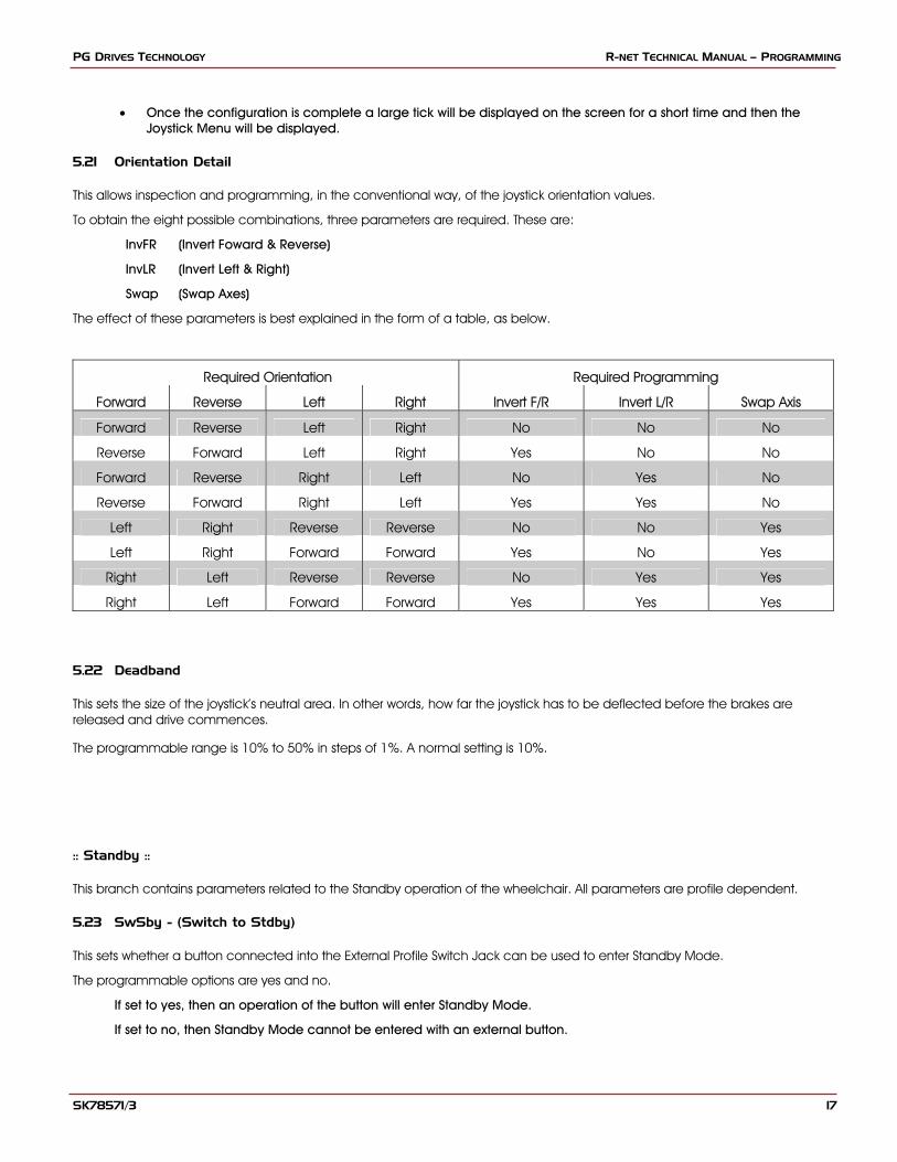
This allows inspection and programming, in the conventional way, of the joystick orientation values.
To obtain the eight possible combinations, three parameters are required. These are:
InvFR (Invert Foward & Reverse)
InvLR (Invert Left & Right)
Swap (Swap Axes)
The effect of these parameters is best explained in the form of a table, as below.
Required Orientation Required Programming
Forward Reverse Left Right Invert F/R Invert L/R Swap Axis
Forward Reverse Left Right No No No
Reverse Forward Left Right Yes No No
Forward Reverse Right Left No Yes No
Reverse Forward Right Left Yes Yes No
Left Right Reverse Reverse No No Yes
Left Right Forward Forward Yes No Yes
Right Left Reverse Reverse No Yes Yes
Right Left Forward Forward Yes Yes Yes
5.22 Deadband
This sets the size of the joystick’s neutral area. In other words, how far the joystick has to be deflected before the brakes are released and drive commences.
The programmable range is 10% to 50% in steps of 1%. A normal setting is 10%.
:: Standby ::
This branch contains parameters related to the Standby operation of the wheelchair. All parameters are profile dependent.
5.23 SwSby - (Switch to Stdby)
This sets whether a button connected into the External Profile Switch Jack can be used to enter Standby Mode.
The programmable options are yes and no.
If set to yes, then an operation of the button will enter Standby Mode.
If set to no, then Standby Mode cannot be entered with an external button.
SK78571/3 17

R-NET OBP MANUAL – PROGRAMMING PG DRIVES TECHNOLOGY
While in Standby Mode, the operation of the control system will depend on the setting of Mode select, see below.
5.24 SbyTm - (Standby Time)
This sets a period of time of joystick inactivity before Standby Mode is entered.
The programmable range is 0 to 200 seconds. A value of 0 means that Standby Mode will never be entered.
5.25 MdeSl - (Mode Select)
This sets whether the joystick can be used to enter different operating Modes while the system is in Standby Mode, or whether Standby Mode is effectively a power-down condition.
The programmable options are yes or no.
If set to yes, then STANDBY will be displayed on the screen and joystick deflections can be used to select different operating Modes. Each of the four joystick directions can be programmed to enter a different Mode. This is set by Standby Forward, Standby Reverse, Standby Left and Standby Right.
If set to no, then STANDBY ON will be displayed on the screen and joystick deflections have no effect. To resume normal operation the Profile Button or an External Profile Switch, if fitted, should be operated.
5.26 Remsl - (Remote Select)
This sets whether Profiles can be selected and entered with joystick deflections.
The programmable options are yes or no.
If set to yes, then Remote Selection Mode can be entered from the Profile. Entry to Remote Selection Mode is via Standby Mode, the Profile Button or an External Profile Switch. The Profile will also be selectable drom Remote Selection Mode.
If set to no, then Remote Selection Mode cannot be entered from the Profile, nor can the Profile be selected from Remote Selection Mode.
In Remote Selection Mode, any other Profile that has Remote Select set to yes can be selected and entered. The screen display will be as below.
Profiles can be selected with left and right joystick deflections. When the desired Profile is selected, it can be entered with a forward deflection of the joystick.
If the standby timer expires while the system is in Remote Selection Mode, the Standby Mode will be re-entered and the Original Profile will still apply.
SK78571/3 18
PG DRIVES TECHNOLOGY R-NET TECHNICAL MANUAL – PROGRAMMING
6 Latched
This branch contains the parameters associated with latched drive and actuator control.
If either latched drive or actuator operation is selected, then an Emergency Stop switch must be connected into the system. The connection point is the External Profile switch jack on the underside of the Joystick Module. To ensure a fail-safe system at all times, a normally-closed switch must be used. Contact your wheelchair supplier for details.
In certain, exceptional conditions, it may be necessary to allow latched operation, but with no Emergency Stop switch, or with a normally open type switch. This can be achieved by setting the parameter, Em Stop Switch, to no. This setting should only be used after a full assessment of all the risks involved, i.e. there is no way of effecting an emergency stop from latched drive or actuator operation.
PGDT accept no liability for losses of any kind resulting from the use of a wheelchair with latched drive or actuator operation and with no Emergency Stop switch or a normally open type switch fitted.
6.1 Drive
This sets the type of latched drive of the wheelchair.
If set to Off, there will be no latched drive.
If set to Step, the latched drive will be step type, but in the forwards direction only.
If set to SRev (Step reverse), the latched drive will be step type in both forwards and reverse.
Stepped drive is when short deflections of the joystick step up or down the latched drive speed of the wheelchair.
If set to Crus (Cruise), the latched drive will be cruise type, but in the forwards direction only.
If set to CRev (Cruise reverse), the latched drive will be cruise type in both forwards and reverse.
Cruise drive is when the wheelchair accelerates while the joystick is deflected, then when the joystick is released the drive continues at the achieved speed.
If any Profile has latched drive set, then an Emergency Sop Switch must be fitted to the system via the Profile jack socket on the Joystick Module. If it is required for the system to operate without an Emergency Stop switch, this can be achieved via the parameter, Emergency Stop Switch.
PGDT accept no liability for losses of any kind resulting from the use of a wheelchair with latched drive or actuator operation and with no normally closed Emergency Stop Switch fitted.
6.2 Acts - (Actuators)
This sets whether the seating functions are latched in operation.
The programmable options are Yes and No.
If set to Yes, then seating control will be latched in operation - i.e. a short joystick deflection will start seat movement.
If set to No, then the seating control will not be latched in operation.
If any Profile has latched actuators set, then an Emergency Sop Switch must be fitted to the system via the Profile jack socket on the Joystick Module. If it is required for the system tooperate without an Emergency Stop switch, this can be achieved via the parameter, Emergency Stop Switch.
PGDT accept no liability for losses of any kind resulting from the use of a wheelchair with latched drive or actuator operation and with no normally closed Emergency Stop Switch fitted.
SK78571/3 19
R-NET OBP MANUAL – PROGRAMMING PG DRIVES TECHNOLOGY
6.3 Time - (Timeout)
This sets the time-out period for latched drive and actuator control.
The programmable range is 0 to 255 Seconds in steps of 1 Second.
The time-out period is the maximum length of time the joystick can be in the neutral position before latched movement ceases. If the period is exceeded, the latched movement will stop. Time-out is therefore an important safety feature that will stop drive or actuator movement should the user be unable to stop the functions in the usual way. It is important that an appropriate time-out period is set.
If a value of 2 or less is set, then the time-out function is disabled. This value should only be used in exceptional circumstances and after all the risks have been fully assessed.
PGDT accept no liability for losses of any kind resulting from the use of a wheelchair with latched drive or actuator operation and with a Latched Timeout value of 0.
6.4 Bleep - (Timeout Bleep)
This can be set to warn the user of the approach of the time-out period.
Programmable options are yes and no.
If set to yes, then an audible warning will be given a few seconds before the expiry of a time-out period.
7 ISM Actuators
This branch contains parameters associated with the performance of the actuators (seat adjustment motors) controlled by the Intelligent Seating Module (ISM).
Each of the actuators can be set independently. Firstly, you must establish to which Channel, 1 to 6, the actuator for the function you wish to adjust is connected to. This will vary depending on the type of wheelchair you are working with. Please contact the wheelchair supplier for more details.
7.1 UpSpd - (Up Speed)
This sets the speed of a particular ISM channel in the Up direction.
Up is defined as pin 1 positive with respect to pin 2 when the joystick is displaced forward and Invert Axis Direction is not set.
Programmable range is 0% to 100% in steps of 1%.
7.2 DnSpd - (Down Speed)
This sets the speed of a particular ISM channel in the Down direction.
Down is defined as pin 2 positive with respect to pin 1 when the joystick is displaced in reverse and Invert Axis Direction is not set.
Programmable range is 0% to 100% in steps of 1%.
7.3 Acc - (Acceleration)
This sets the acceleration rate for a particular ISM channel.
Programmable range is 1 to 100 in steps of 1.
SK78571/3 20
PG DRIVES TECHNOLOGY R-NET TECHNICAL MANUAL – PROGRAMMING
This parameter must be set to 100% on systems that use automatic endstops, i.e. those that do not use micro-switches at the end of actuator travel. If the value is not set to 100%, then the automatic endstop function will not operate and damage to the actuator motor or the wheelchair frame may occur.
7.4 Dec - (Deceleration)
This sets the deceleration rate for a particular ISM channel.
Programmable range is 1 to 100 in steps of 1.
This parameter must be set to 100% on systems that use automatic endstops, i.e. those that do not use micro-switches at the end of actuator travel. If the value is not set to 100%, then the automatic endstop function will not operate and damage to the actuator motor or the wheelchair frame may occur.
8 SM Actuators
This branch contains parameters associated with the performance of the actuators (seat adjustment motors) controlled by the Seating Module.
Each of the actuators can be set independently. Firstly, you must establish to which Axis, 1 to 12, you wish to adjust. This will vary depending on the type of wheelchair you are working with. Please contact the wheelchair supplier for more details.
8.1 Up Speed - (UpSpd)
This sets the speed of a particular SM Axis in the Up direction.
Up is defined as pin 1 positive with respect to pin 2 when the joystick is displaced forward.
Programmable range is 0% to 100% in steps of 1%.
8.2 Down Speed - (DnSpd)
This sets the speed of a particular SM Axis in the Down direction.
Down is defined as pin 2 positive with respect to pin 1 when the joystick is displaced in reverse.
Programmable range is 0% to 100% in steps of 1%.
SK78571/3 21
R-NET OBP MANUAL – PROGRAMMING PG DRIVES TECHNOLOGY
9 Profiles
This branch contains parameters associated with the setting up of Profiles.
9.1 PrfEn - (Profile Enable)
This sets whether a particular Profile is available for selection by the wheelchair user.
10 Modes
This branch contains parameters associated with the setting up of Modes.
10.1 Prf - (Mode Enabled)
This sets which operating Modes are available in each of the Profiles.
The programmable options are yes and no.
If set to yes, then the Mode is available within a given Profile..
If set to no, then the Mode is not available within a given Profile.
11 Input Devices
This branch contains parameters associated with the setting up of input devices(ID).
11.1 Type - (ID Type)
Each Profile can be set to work with any type of Input Device, or only with a specific type of Input Device. The parameter, Input Device Type, is used to set this function and there are currently four settings – Universal, JSM, Attendant and Omni.
Uni: Universal – any type of Input Device can be in control. If multiple Input Devices are connected, it will be the one that powered-up the system that will be in control
JSM: Joystick – only a standard Joystick Module (JSM) will be able to have control.
Omn: Omni – only a specialty control interface, such as a PGDT Omni type product will be able to have control.
Att: Attendant – only an Attendant operated device will be able to have control.
If set to Universal, then any Input Device can control the Profile, and it will be the Input Device that was used to power-up the system that will be in control.
If set to anything other than Universal, then only the programmed type of Input Device can control the Profile.
SK78571/3 22
PG DRIVES TECHNOLOGY R-NET TECHNICAL MANUAL – PROGRAMMING
12 System
This branch contains miscellaneous utilities for system diagnostics and set-up.
12.1 Diagnostics
This accesses the error logs in each of the modules connected in the system. Each module has its own individual log, thereby making it much simpler to isolate the cause of a system problem.
12.2 Timers
This acessess the run timer for the wheelchair. This timer displays in hours and minutes exactly how long the wheelchair has been driven.
12.3 Joystick Calibration
If a new joystick is fitted to a Joystick Module, then this calibration procedure must be performed. If it is not, the wheelchair may not drive in a straight line or reach maximum speed.
The procedure is automatic, simply follow the on-screen instructions. Values for both the forward/reverse and left/right joystick axes will be displayed. Alongside each value will be a X or a √ symbol.
X – indicates the axis value is outside of the permitted calibration range for the particular joystick direction.
√ – indicates the axis value is within the permitted calibration value for the particular joystick direction.
Simply deflect the joystick in the instructed direction until both values are within the permitted ranges. Repeat for all four directions.
A large tick will be displayed on screen, for a short period of time, when the calibration has been completed successfully. The screen will then return to the System Menu.
12.4 Copy Profiles
This allows all the values from one Profile to be copied into another. This is useful when only small differences are required between some Profiles.
There are on-screen instructions. Firstly, you will be asked to select a Source Profile. This is the Profile you wish to copy. You will then be asked to select a Destination Profile. This is the Profile that you wish to copy the Source Profile to.
Selection is made by deflecting the joystick to the right when on the correct Profile.
12.4 Load Presets - To be included in future releases.
This allows you to quickly restore programmable values for each of the Profiles to their original, factory settings.
You can also preset the global parameters, i.e. those that are not Profile dependent.
12.5 Adjust Contrast
This allows adjustment of the contrast on the LCD screen. Simply use the Speed Wheel to adjust the contrast up or down.
SK78571/3 23

R-NET OBP MANUAL – PROGRAMMING PG DRIVES TECHNOLOGY
13 OBP Quick Reference Guide
Speeds
Fo
Re
Tur
Drive
Po
Tor
Tre
Controls
Glo
Profiled Controls
Sleep Timer
Chge Mde in Drv
Background
Joystick
Active Throw
Throw Detail
Active Orientation
Orientation Detail
Deadband
Standby
Switch to Stdby
Standby Time
Mode Select
Remote Select
Latched
Drive
Actuators
Timeout
Timeout Bleep
ISM Actuators
Up Speed
Down Speed
Acceleration
Deceleration
SM Actuators
Up Speed
Down Speed
Profiles
Profile Enable
Modes
Modes
Input Devices
Type
System
Diagnostics
Timers
Joystick Calibration
Copy Profiles
Load Presets
Adjust Contrast
24
rward
Fwd Accel Max
Fwd Accel Min
Fwd Decel Min
Fwd Decel Max
Fwd Speed Max
Fwd Speed Min
verse
Rev Accel Max
Rev Accel Min
Rev Decel Min
Rev Decel Max
Rev Speed Max
Rev Speed Min
n
Turn Accel Max
Turn Accel Min
Turn Decel Min
Turn Decel Max
Turn Speed Max
Turn Speed Min
wer
que
mor Damping
bal Controls
Steer Correct
Sounder Volume
Endstop Bleep
Act. Entry Axis
Chge Prf in Drv
Speed Adjust
Speed Adj in Drv
Momentary Screens
Rev Driving Alarm
Em Stop Switch
Lock Fn Enable
Display Speed
Max Display Speed
Power-up Mode
SK78571/3

PG DRIVES TECHNOLOGY R-NET OBP MANUAL – DIAGNOSTICS
SK78571/3 25
R-NET OBP MANUAL – DIAGNOSTICS PG DRIVES TECHNOLOGY
CHAPTER 2 – DIAGNOSTICS
SK78571/3 26

PG DRIVES TECHNOLOGY R-NET OBP MANUAL – DIAGNOSTICS
SK78571/3 27

R-NET OBP MANUAL – DIAGNOSTICS PG DRIVES TECHNOLOGY
1 Introduction
The primary objective of this chapter is to assist service personnel in finding the likely area of a detected trip within the whole wheelchair electrical system. It is important to realize that even though the control system is signalling a trip, it may not be the control system itself that is defective. This is because the control system is able to detect problems in other electrical components (motors, batteries, solenoid brakes, etc.) or, more importantly, the wiring to them. When a control system has detected a trip, a system trip is indicated.
This chapter covers the diagnostic process for the R-net control system, including; JSM trip display analysis, accessing the system log using OBP, trip identification and possible restorative guidelines.
To diagnose a trip condition when no LCD Module is connected please connected the R-net Control System to a DTT Handheld Programmer or a PC with R-net PC Programmer installed.
Diagnostics should only be conducted by healthcare professionals with in-depth knowledge of PGDT electronic control systems. An incorrect or badly effected repair could result in an unsafe set-up of a wheelchair. PGDT accept no liability for losses of any kind arising from an incorrect or badly effected repair.
1.1 Diagnostic Procedure
To diagnose a trip please follow this procedure:
• Read and note the Trip Text displayed, the Identified Module and the Trip Code. Refer to section 2.
• Switch off the control system.
• Make sure that all connectors on the listed Module and the wheelchair are mated securely.
• Check the condition of the battery.
• Find the definition of the Trip Text, and take the required action. Refer to section 3.
• Switch on the control system again and try to drive the wheelchair. If the safety circuits operate again, switch off and do not try to use the wheelchair.
Contact your service agent.
2 Diagnostic Screens
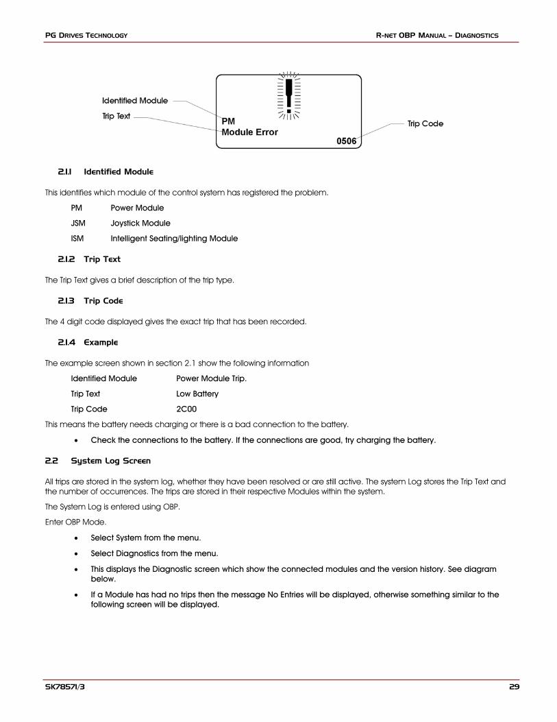
2.1 Current Diagnostic Screen
When the control system safety circuits have operated and the control system has been prevented from moving the wheelchair a diagnostics screen will be displayed.
This indicates a system trip, i.e. the R-net has detected a problem somewhere in the wheelchair’s electrical system.
If the error is in a non-active module, for example in the ISM but with a Drive Mode is selected, then drive will still be possible, however, the diagnostic screen will appear intermittently.
SK78571/3 28
PG DRIVES TECHNOLOGY R-NET OBP MANUAL – DIAGNOSTICS
2.1.1 Identified Module
This identifies which module of the control system has registered the problem.
PM Power Module
JSM Joystick Module
ISM Intelligent Seating/lighting Module
2.1.2 Trip Text
The Trip Text gives a brief description of the trip type.
2.1.3 Trip Code
The 4 digit code displayed gives the exact trip that has been recorded.
2.1.4 Example
The example screen shown in section 2.1 show the following information
Identified Module Power Module Trip.
Trip Text Low Battery
Trip Code 2C00
This means the battery needs charging or there is a bad connection to the battery.
• Check the connections to the battery. If the connections are good, try charging the battery.
2.2 System Log Screen
All trips are stored in the system log, whether they have been resolved or are still active. The system Log stores the Trip Text and the number of occurrences. The trips are stored in their respective Modules within the system.
The System Log is entered using OBP.
Enter OBP Mode.
• Select System from the menu.
• Select Diagnostics from the menu.
• This displays the Diagnostic screen which show the connected modules and the version history. See diagram below.
• If a Module has had no trips then the message No Entries will be displayed, otherwise something similar to the following screen will be displayed.
SK78571/3 29

R-NET OBP MANUAL – DIAGNOSTICS PG DRIVES TECHNOLOGY
SK78571/3 30
PG DRIVES TECHNOLOGY R-NET OBP MANUAL – DIAGNOSTICS
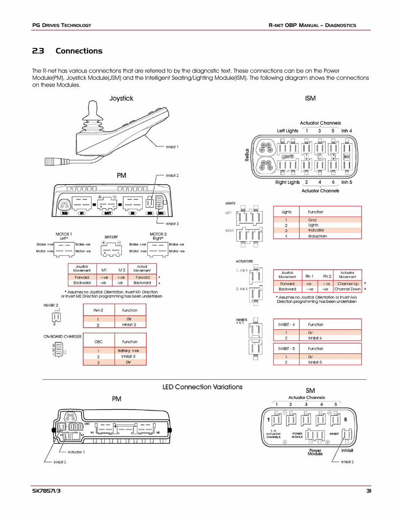
2.3 Connections
The R-net has various connections that are referred to by the diagnostic text. These connections can be on the Power Module(PM), Joystick Module(JSM) and the Intelligent Seating/Lighting Module(ISM). The following diagram shows the connections on these Modules.
SK78571/3 31
R-NET OBP MANUAL – DIAGNOSTICS PG DRIVES TECHNOLOGY
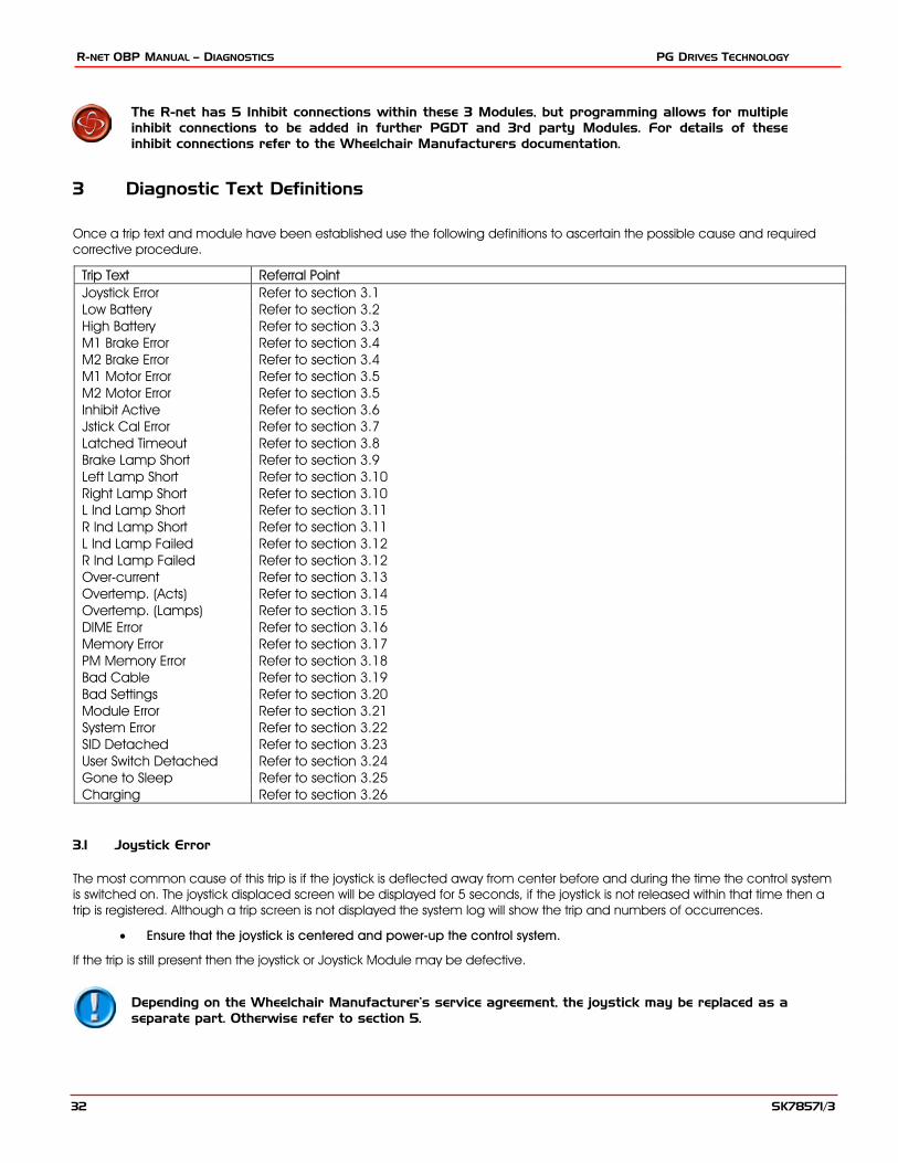
The R-net has 5 Inhibit connections within these 3 Modules, but programming allows for multiple inhibit connections to be added in further PGDT and 3rd party Modules. For details of these inhibit connections refer to the Wheelchair Manufacturers documentation.
3 Diagnostic Text Definitions
Once a trip text and module have been established use the following definitions to ascertain the possible cause and required corrective procedure.
Trip Text Referral Point Joystick Error Refer to section 3.1 Low Battery Refer to section 3.2 High Battery Refer to section 3.3 M1 Brake Error Refer to section 3.4 M2 Brake Error Refer to section 3.4 M1 Motor Error Refer to section 3.5 M2 Motor Error Refer to section 3.5 Inhibit Active Refer to section 3.6 Jstick Cal Error Refer to section 3.7 Latched Timeout Refer to section 3.8 Brake Lamp Short Refer to section 3.9 Left Lamp Short Refer to section 3.10 Right Lamp Short Refer to section 3.10 L Ind Lamp Short Refer to section 3.11 R Ind Lamp Short Refer to section 3.11 L Ind Lamp Failed Refer to section 3.12 R Ind Lamp Failed Refer to section 3.12 Over-current Refer to section 3.13 Overtemp. (Acts) Refer to section 3.14 Overtemp. (Lamps) Refer to section 3.15 DIME Error Refer to section 3.16 Memory Error Refer to section 3.17 PM Memory Error Refer to section 3.18 Bad Cable Refer to section 3.19 Bad Settings Refer to section 3.20 Module Error Refer to section 3.21 System Error Refer to section 3.22 SID Detached Refer to section 3.23 User Switch Detached Refer to section 3.24 Gone to Sleep Refer to section 3.25 Charging Refer to section 3.26
3.1 Joystick Error
The most common cause of this trip is if the joystick is deflected away from center before and during the time the control system is switched on. The joystick displaced screen will be displayed for 5 seconds, if the joystick is not released within that time then a trip is registered. Although a trip screen is not displayed the system log will show the trip and numbers of occurrences.
• Ensure that the joystick is centered and power-up the control system.
If the trip is still present then the joystick or Joystick Module may be defective.
Depending on the Wheelchair Manufacturer’s service agreement, the joystick may be replaced as a separate part. Otherwise refer to section 5.
SK78571/3 32
PG DRIVES TECHNOLOGY R-NET OBP MANUAL – DIAGNOSTICS
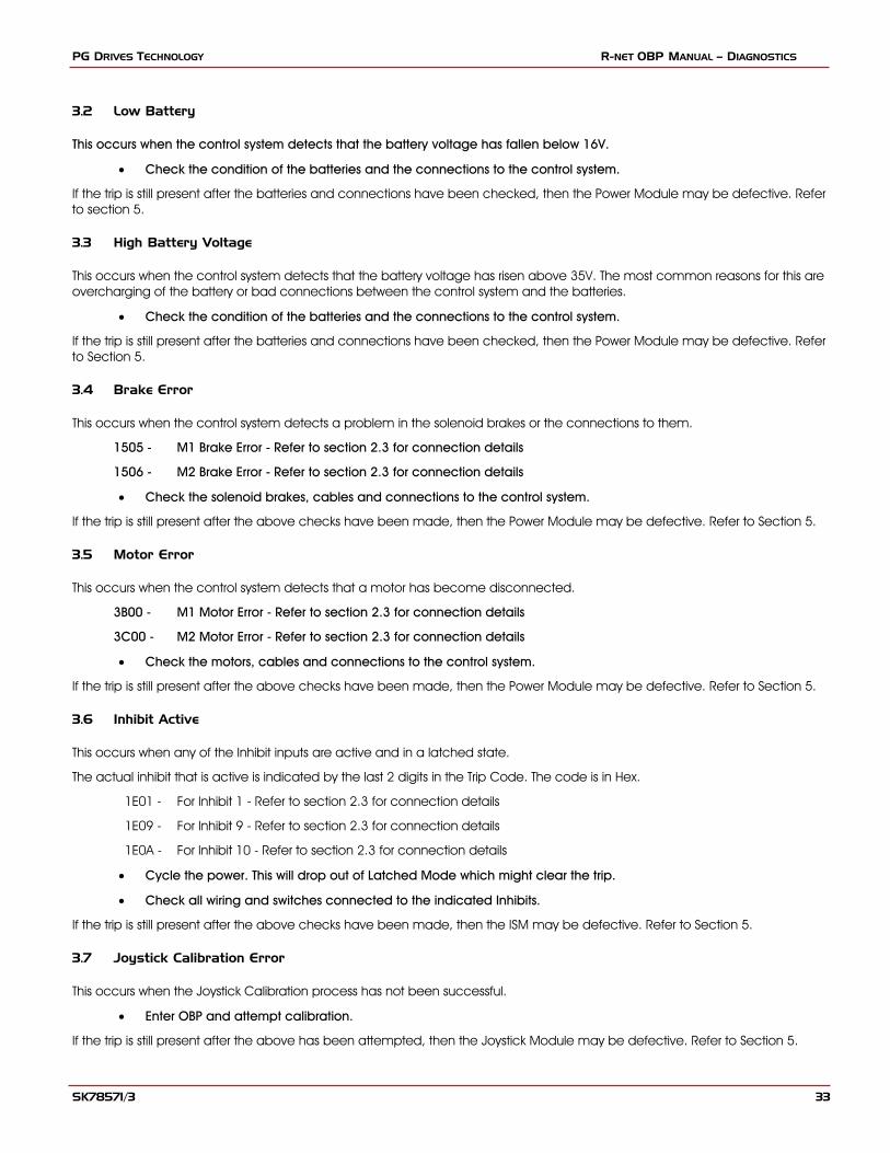
3.2 Low Battery
This occurs when the control system detects that the battery voltage has fallen below 16V.
• Check the condition of the batteries and the connections to the control system.
If the trip is still present after the batteries and connections have been checked, then the Power Module may be defective. Refer to section 5.
3.3 High Battery Voltage
This occurs when the control system detects that the battery voltage has risen above 35V. The most common reasons for this are overcharging of the battery or bad connections between the control system and the batteries.
• Check the condition of the batteries and the connections to the control system.
If the trip is still present after the batteries and connections have been checked, then the Power Module may be defective. Refer to Section 5.
3.4 Brake Error
This occurs when the control system detects a problem in the solenoid brakes or the connections to them.
1505 - M1 Brake Error - Refer to section 2.3 for connection details
1506 - M2 Brake Error - Refer to section 2.3 for connection details
• Check the solenoid brakes, cables and connections to the control system.
If the trip is still present after the above checks have been made, then the Power Module may be defective. Refer to Section 5.
3.5 Motor Error
This occurs when the control system detects that a motor has become disconnected.
3B00 - M1 Motor Error - Refer to section 2.3 for connection details
3C00 - M2 Motor Error - Refer to section 2.3 for connection details
• Check the motors, cables and connections to the control system.
If the trip is still present after the above checks have been made, then the Power Module may be defective. Refer to Section 5.
3.6 Inhibit Active
This occurs when any of the Inhibit inputs are active and in a latched state.
The actual inhibit that is active is indicated by the last 2 digits in the Trip Code. The code is in Hex.
1E01 - For Inhibit 1 - Refer to section 2.3 for connection details
1E09 - For Inhibit 9 - Refer to section 2.3 for connection details
1E0A - For Inhibit 10 - Refer to section 2.3 for connection details
• Cycle the power. This will drop out of Latched Mode which might clear the trip.
• Check all wiring and switches connected to the indicated Inhibits.
If the trip is still present after the above checks have been made, then the ISM may be defective. Refer to Section 5.
3.7 Joystick Calibration Error
This occurs when the Joystick Calibration process has not been successful.
• Enter OBP and attempt calibration.
If the trip is still present after the above has been attempted, then the Joystick Module may be defective. Refer to Section 5.
SK78571/3 33
R-NET OBP MANUAL – DIAGNOSTICS PG DRIVES TECHNOLOGY
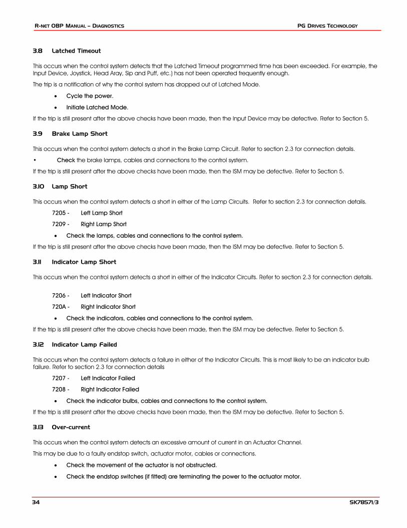
3.8 Latched Timeout
This occurs when the control system detects that the Latched Timeout programmed time has been exceeded. For example, the Input Device, Joystick, Head Aray, Sip and Puff, etc.) has not been operated frequently enough.
The trip is a notification of why the control system has dropped out of Latched Mode.
• Cycle the power.
• Initiate Latched Mode.
If the trip is still present after the above checks have been made, then the Input Device may be defective. Refer to Section 5.
3.9 Brake Lamp Short
This occurs when the control system detects a short in the Brake Lamp Circuit. Refer to section 2.3 for connection details.
• Check the brake lamps, cables and connections to the control system.
If the trip is still present after the above checks have been made, then the ISM may be defective. Refer to Section 5.
3.10 Lamp Short
This occurs when the control system detects a short in either of the Lamp Circuits. Refer to section 2.3 for connection details.
7205 - Left Lamp Short
7209 - Right Lamp Short
• Check the lamps, cables and connections to the control system.
If the trip is still present after the above checks have been made, then the ISM may be defective. Refer to Section 5.
3.11 Indicator Lamp Short
This occurs when the control system detects a short in either of the Indicator Circuits. Refer to section 2.3 for connection details.
7206 - Left Indicator Short
720A - Right Indicator Short
• Check the indicators, cables and connections to the control system.
If the trip is still present after the above checks have been made, then the ISM may be defective. Refer to Section 5.
3.12 Indicator Lamp Failed
This occurs when the control system detects a failure in either of the Indicator Circuits. This is most likely to be an indicator bulb failure. Refer to section 2.3 for connection details
7207 - Left Indicator Failed
7208 - Right Indicator Failed
• Check the indicator bulbs, cables and connections to the control system.
If the trip is still present after the above checks have been made, then the ISM may be defective. Refer to Section 5.
3.13 Over-current
This occurs when the control system detects an excessive amount of current in an Actuator Channel.
This may be due to a faulty endstop switch, actuator motor, cables or connections.
• Check the movement of the actuator is not obstructed.
• Check the endstop switches (if fitted) are terminating the power to the actuator motor.
SK78571/3 34

PG DRIVES TECHNOLOGY R-NET OBP MANUAL – DIAGNOSTICS
If the trip is still present after the above checks have been made, then the ISM may be defective. Refer to Section 5.
3.14 Overtemp (acts)
This occurs when the control system detects that the ISM’s actuator circuitry has become too hot. The control system will cease drive to the actuator motor in question.
• Allow the ISM to cool.
• If the ISM is frequently overheating check the condition of the actuator motors and the connections to them.
• If the trip persists contact your service agent.
3.15 Overtemp (lamps)
This occurs when the control system detects that ISM’s lighting circuitry has become too hot. The control system will cease supplying current to the lamp in question.
• Allow the ISM to cool.
• If the ISM is frequently overheating check the condition of all the connected bulbs and lamps.
• If the trip persists contact your service agent.
3.16 DIME Error
This occurs when the control system detects an identification conflict between two modules in the system.
If a new module has been introduced:
• Disconnect the new module and cycle the power.
• If no trip is present connect the new module to the system and cycle the power.
• If the trip reappears then the new module must be the cause of the problem.
If there has been no additions:
• Disconnect one module at a time and cycle the power.
If the trip is still present after the above checks have been made, contact your service agent.
3.17 Memory Error
This is a non specific memory error which could be caused by any of the modules within the system.
• Check all cables and connections.
• Cycle the power.
If the trip is still present and the system contains 3rd party Modules:
• Disconnect all the non PGDT modules and cycle the power.
If this has cleared the trip:
• Connect each 3rd party module in turn, cycling the power each time.
• If the trip reappears after one of the power cycles then the last module to have been added to the system must be defective.
If the trip is still present after the above checks have been made, then the PM may be defective. Refer to Section 5.
3.18 PM Memory Error
This is a specific Power Module based trip.
• Check all cables and connections.
SK78571/3 35
R-NET OBP MANUAL – DIAGNOSTICS PG DRIVES TECHNOLOGY
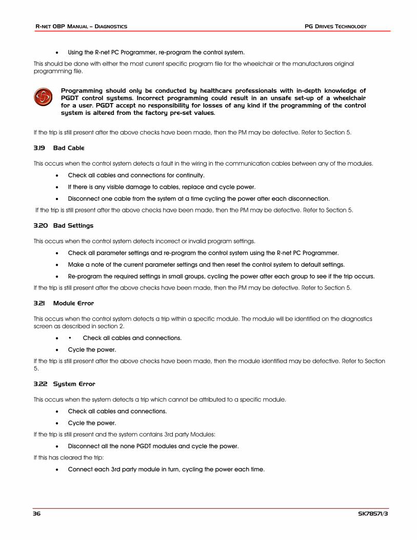
• Using the R-net PC Programmer, re-program the control system.
This should be done with either the most current specific program file for the wheelchair or the manufacturers original programming file.
Programming should only be conducted by healthcare professionals with in-depth knowledge of PGDT control systems. Incorrect programming could result in an unsafe set-up of a wheelchair for a user. PGDT accept no responsibility for losses of any kind if the programming of the control system is altered from the factory pre-set values.
If the trip is still present after the above checks have been made, then the PM may be defective. Refer to Section 5.
3.19 Bad Cable
This occurs when the control system detects a fault in the wiring in the communication cables between any of the modules.
• Check all cables and connections for continuity.
• If there is any visible damage to cables, replace and cycle power.
• Disconnect one cable from the system at a time cycling the power after each disconnection.
If the trip is still present after the above checks have been made, then the PM may be defective. Refer to Section 5.
3.20 Bad Settings
This occurs when the control system detects incorrect or invalid program settings.
• Check all parameter settings and re-program the control system using the R-net PC Programmer.
• Make a note of the current parameter settings and then reset the control system to default settings.
• Re-program the required settings in small groups, cycling the power after each group to see if the trip occurs.
If the trip is still present after the above checks have been made, then the PM may be defective. Refer to Section 5.
3.21 Module Error
This occurs when the control system detects a trip within a specific module. The module will be identified on the diagnostics screen as described in section 2.
• • Check all cables and connections.
• Cycle the power.
If the trip is still present after the above checks have been made, then the module identified may be defective. Refer to Section 5.
3.22 System Error
This occurs when the system detects a trip which cannot be attributed to a specific module.
• Check all cables and connections.
• Cycle the power.
If the trip is still present and the system contains 3rd party Modules:
• Disconnect all the none PGDT modules and cycle the power.
If this has cleared the trip:
• Connect each 3rd party module in turn, cycling the power each time.
SK78571/3 36

PG DRIVES TECHNOLOGY R-NET OBP MANUAL – DIAGNOSTICS
• If the trip reappears after one of the power cycles then the last module to have been added to the system must be defective.
If the trip is still present after the above checks have been made, then the PGDT control system may be defective. Refer to Section 5.
3.23 SID Disconnected
The Omni has detected that the Specialty Input Device (SID) has become disconnected.
• Check all cables and connectors between the Omni and the SID.
If the error persists:
• Check that the setting of the parameter, 9-Way Detect, is appropriate for the SID that is being used. For example, if the SID has no detect-link, then this parameter should be set to Off.
If the trip is still present after the above checks have been made, then the Input Device may be defective. Contact your service agent.
3.24 User Switch Detached
The Omni has detected that the User Switch has become disconnected.
• Check all cables and connectors between the Omni and the User Switch.
If the trip is still present after the above checks have been made, then the User Switch may be defective. Contact your service agent.
If it is required to use the Omni without a User Switch being connected, then the parameter, Switch Detect, should be set to Off. If a User Switch is not used the responsibility for that decision lies with the healthcare professional.
Because a disconnected User Switch means there is no emergency stop function, PG Drives Technology recommend that Switch Detect is this option is always set to On. PG Drives Technology will accept no liability for any losses resulting from any other setting of this parameter.
3.25 Gone to Sleep
This occurs when the control system has been left inactive for a time greater than the parameter Sleep Timer.
An entry is made in the system log each time this occurs.
3.26 Charging
This occurs when the control system detects that a charger is connected to either Inhibit 1 or Inhibit 3. Refer to section 2.3 for connection details
The Battery charging screen will be displayed during charger connection.
An entry is made in the system log each time this occurs.
If an On-Board Charger is used:
• Disconnect the charger from the AC supply.
If an Off-Board Charger is used:
• Disconnect the charger from the Wheelchair.
If the trip is still present after the charger has been disconnected then the Joystick Module may be defective. Refer to Section 5.
SK78571/3 37
R-NET OBP MANUAL – DIAGNOSTICS PG DRIVES TECHNOLOGY
4 Basic Tests
After a repair has been completed, the following tests should be carried out. These are minimum recommendations, depending on the nature of the original trip then additional tests may be required.
These tests are a minimum recommendation only. It is the responsibility of the service person(s) to perform other tests relevant to the original trip and wheelchair type are carried out. Refer to the wheelchair’s Technical Manual for exact information of other tests. PGDT accept no liability for losses of any kind arising from the carrying out of the described tests, or from not carrying out additional relevant tests.
These tests should be conducted in an open space and a restraining device such as a seat belt should always be used. PGDT accepts no liability for losses of any kind arising from failure to comply with this condition.
4.1 General Inspection
Make sure all connectors are securely mated.
• Check the condition of all cables and connectors for damage.
• Check the rubber gaiter or boot around the base of the joystick shaft for damage. Check visually only, do not handle the gaiter.
• Make sure that all components of the control system are securely mounted.
• Do not overtighten any securing screws.
4.2 Brake Test
These tests should be carried out on a level floor with at least one meter clear space around the wheelchair.
• Switch on the control system.
• Check the screen remains on after initialisation.
• Push the joystick slowly forwards until you hear the parking brakes operate. The wheelchair may start to move.
• Immediately release the joystick. You must be able to hear each parking brake operate within 2 seconds.
• Repeat the test a further three times, pushing the joystick slowly backwards, left and right.
4.3 Drive Test
With the maximum speed control in the minimum position, drive the wheelchair in all directions, ensuring the drive is comfortable and easy to control for the user.
Repeat the above but with the speed control set to maximum.
4.4 Gradient Test
Before carrying out this test ensure another person is present to prevent the wheelchair from tipping backwards.
Drive the wheelchair forwards up its maximum rated gradient. While on the gradient release the joystick and ensure the wheelchair comes to rest and the brakes are applied without the front wheels lifting of the ground.
Deflect the joystick forwards and continue driving up the slope. Ensure the pick up is smooth and positive.
SK78571/3 38

PG DRIVES TECHNOLOGY R-NET OBP MANUAL – DIAGNOSTICS
Stop the wheelchair and reverse down the gradient. While on the gradient release the joystick and ensure the wheelchair comes to rest and the brakes are applied without the front wheels lifting of the ground.
4.5 Lights, Indicators and Hazard Lamps Test
If lights are fitted:
• Visually check each bulb for correct illumination.
• Check each bulb for correct illumination and that the flashrate is 1.5Hz ± 0.5Hz.
• Disconnect each bulb in turn and check that the remaining bulb for that side flashes at 3Hz ± 0.5Hz.
If hazard lamps are fitted:
• check each bulb for correct illumination and that the flashrate is 1.5Hz ± 0.5Hz.
4.6 Actuator Test
If actuators are fitted:
• Check each motor for correct direction of movement.
• Ensure the mechanical end-stops are secure and that they stall the actuator motors, thus operating the ISM’s automatic end-stop detection.
46.7 Inhibit Input Test
Insert an appropriate battery charger, or equivalent inhibit connection, into the Charger Connector on the JSM and ensure that drive is inhibited.
If Inhibits 2, 3, 4 and 5 are used for inhibit or speed limiting purposes, suitable tests should be devised to ensure correct operation.
SK78571/3 39

R-NET OBP MANUAL – DIAGNOSTICS PG DRIVES TECHNOLOGY
5 Servicing of Defective Units
Excluding specific OEM approved replacement parts (for details of these contact the wheelchair manufacturer), there are no serviceable parts in the R-net control system. Consequently, any defective units must be returned to PGDT or a PGDT approved service organization for repair.
Any replacement work carried out without the wheelchair manufacturer’s permission will invalidate the control system’s warranty.
Opening or making any unauthorized adjustments or modifications to the R-net control system or its components will invalidate any warranty and may result in hazards to the vehicle user, and is strictly forbidden.
PGDT accept no liability for losses of any kind arising from unauthorized opening, adjustments or modifications to a any component of the R-net control system.
SK78571/3 40
PG DRIVES TECHNOLOGY R-NET TECHNICAL MANUAL – SPECIFICATIONS
CHAPTER 3 – WARNING SUMMARY
SK78571/3 41

R-NET TECHNICAL MANUAL – SPECIFICATIONS PG DRIVES TECHNOLOGY
SK78571/3 42
PG DRIVES TECHNOLOGY R-NET TECHNICAL MANUAL – SPECIFICATIONS
1 Introduction
This section summarizes all of the very important warnings that appear throughout the text of this manual. Do not install, maintain or operate the machine without reading, understanding and observing the following warnings. Failure to observe these warnings could result in UNSAFE CONDITIONS for the user of a machine or affect the reliability of the control system. PG Drives Technology accepts no liability for losses of any kind arising from failure to comply with any of the conditions in the warnings listed below. Failure to observe these warnings will invalidate the R-Net warranty.
The machine manufacturer may wish to use this section as a check list, to ensure the risk areas identified below have been addressed within their own machine designs and associated documentation.
2 Warnings
2.1 Introduction
Programming should only be conducted by healthcare professionals with in-depth knowledge of PGDT control systems. Incorrect programming could result in an unsafe set-up of a wheelchair for a user. PGDT accept no responsibility for losses of any kind if the programming of the control system is altered from the factory pre-set values. Chapter 1 section 1.
2.2 Entering OBP Mode
If the keycode method is set, then it may be possible for a wheelchair user to gain entry to the OBP function. PGDT accept no liability for losses of any kind if this method of OBP is set. PGDT also accept no liability for losses of any kind if OBP access is gained by unauthorised personnel obtaining a dongle. Chapter 1 section 1.1.
2.3 Trmr - (Tremor Damping)
If using high values of Tremor Damping, pay particular attention to the stopping distance of the wheelchair, as it will be increased. Chapter 1 section 4.3.
These tests should be conducted in an open space and a restraining device such as a set belt should always be used. PGDT accepts no liability for losses of any kind arising from failure to comply with this condition.
2.4 Emergency Stop (Emergency Stop Switch)
PGDT accept no liability for losses of any kind resulting from the use of a wheelchair with latched drive or actuator operation and with no normally closed Emergency Stop Switch fitted. Chapter 1 section 5.10.
2.5 Latched
PGDT accept no liability for losses of any kind resulting from the use of a wheelchair with latched drive or actuator operation and with no Emergency Stop switch or a normally open type switch fitted. Chapter 1 section 6.
SK78571/3 43
R-NET TECHNICAL MANUAL – SPECIFICATIONS PG DRIVES TECHNOLOGY
2.6 Drive
PGDT accept no liability for losses of any kind resulting from the use of a wheelchair with latched drive or actuator operation and with no normally closed Emergency Stop Switch fitted. Chapter 1 section 6.1.
2.7 Acts - (Actuators)
PGDT accept no liability for losses of any kind resulting from the use of a wheelchair with latched drive or actuator operation and with no normally closed Emergency Stop Switch fitted. Chapter 1 section 6.2.
2.8 Time - (Timeout)
PGDT accept no liability for losses of any kind resulting from the use of a wheelchair with latched drive or actuator operation and with a Latched Timeout value of 0. Chapter 1 section 6.3.
2.9 Acc - (Acceleration)
This parameter must be set to 100% on system s that use automatic endstops, i.e. those that do not use micro-switches at the end of actuator travel. If the value is not set to 100%, then the automatic endstop function will not operate and damage to the actuator motor or the wheelchair frame may occur. Chapter 1 section 7.3.
2.10 Dec - (Deceleration)
This parameter must be set to 100% on system s that use automatic endstops, i.e. those that do not use micro-switches at the end of actuator travel. If the value is not set to 100%, then the automatic endstop function will not operate and damage to the actuator motor or the wheelchair frame may occur. Chapter 1 section 7.4.
2.11 Introduction
Diagnostics should only be conducted by healthcare professionals with in-depth knowledge of PGDT electronic control systems. An incorrect or badly effected repair could result in an unsafe set-up of a wheelchair. PGDT accept no liability for losses of any kind arising from an incorrect or badly effected repair. Chapter 2 section 1.
2.12 PM Memory Error
Programming should only be conducted by healthcare professionals with in-depth knowledge of PGDT control systems. Incorrect programming could result in an unsafe set-up of a wheelchair for a user. PGDT accept no responsibility for losses of any kind if the programming of the control system is altered from the factory pre-set values. Chapter 2 section 3.18.
2.13 Basic Tests
These tests are a minimum recommendation only. It is the responsibility of the service person(s) to perform other tests relevant to the original trip and wheelchair type are carried out. Refer to the wheelchair’s Technical Manual for exact information of other tests. PGDT accept no liability
SK78571/3 44

PG DRIVES TECHNOLOGY R-NET TECHNICAL MANUAL – SPECIFICATIONS
SK78571/3 45
for losses of any kind arising from the carrying out of the described tests, or from not carrying out additional relevant tests.
These tests should be conducted in an open space and a restraining device such as a seat belt should always be used. PGDT accepts no liability for losses of any kind arising from failure to comply with this condition. Chapter 2 section 4.
2.14 Servicing of Defective Units
Any replacement work carried out without the wheelchair manufacturer’s permission will invalidate the control system’s warranty.
PGDT accept no liability for losses of any kind arising from unauthorized opening, adjustments or modifications to a any component of a control system. Chapter 2 section 5.